EP2327345A2 - Floor to ceiling support pole - Google Patents
Floor to ceiling support pole Download PDFInfo
- Publication number
- EP2327345A2 EP2327345A2 EP10251841A EP10251841A EP2327345A2 EP 2327345 A2 EP2327345 A2 EP 2327345A2 EP 10251841 A EP10251841 A EP 10251841A EP 10251841 A EP10251841 A EP 10251841A EP 2327345 A2 EP2327345 A2 EP 2327345A2
- Authority
- EP
- European Patent Office
- Prior art keywords
- pole
- sections
- section
- floor
- length
- Prior art date
- Legal status (The legal status is an assumption and is not a legal conclusion. Google has not performed a legal analysis and makes no representation as to the accuracy of the status listed.)
- Withdrawn
Links
Images

Classifications
-
- A—HUMAN NECESSITIES
- A47—FURNITURE; DOMESTIC ARTICLES OR APPLIANCES; COFFEE MILLS; SPICE MILLS; SUCTION CLEANERS IN GENERAL
- A47K—SANITARY EQUIPMENT NOT OTHERWISE PROVIDED FOR; TOILET ACCESSORIES
- A47K3/00—Baths; Douches; Appurtenances therefor
- A47K3/28—Showers or bathing douches
- A47K3/30—Screens or collapsible cabinets for showers or baths
Definitions
- the present invention relates generally to a pole and particularly to a floor to ceiling support pole, that is a pole which is generally fixed between upper and lower surfaces in a room.
- Floor to ceiling poles are well known and used for a variety of purposes including as a "grab rail" to facilitate activities, and as a structure to which other structures can be secured.
- floor to ceiling poles are used extensively in the healthcare industry where the elderly and/or disabled require assistance to move and position themselves. Poles can be provided at appropriate positions within a room either by themselves or in conjunction with other bathroom fixtures such as shower or bath panels.
- poles are supplied as a single fixed length. Because the height of a room in which a pole is required can vary considerably, the pole is cut to size on site and fixed into position. However, the length of such poles causes problems, particularly for transport and packaging.
- the present invention seeks to address the problems with known floor to ceiling poles.
- a shower screen assembly floor to ceiling support pole the pole being fixable to one or more shower screen panels so as to form an integral part of a screen assembly and comprising two or more elongate pole sections which are longitudinally telescopic to allow adjustment of the length of the pole.
- the pole By forming the pole so that it is connectable to and forms an integral part of the shower screen assembly it can contribute to the rigidity of the overall screen or panel structure.
- the pole may comprise three pole sections.
- the pole may comprise an upper, ceiling-engaging section, a lower, floor-engaging section, and a middle, link section.
- pole sections can be provided under the same principle of a telescoping pole.
- the number of sections could, for example, be selected on the basis of a required maximum section length.
- pole sections may be the intermediate, or link sections which telescope inside both of two adjacent sections.
- the sections may increase or decrease in diameter along the length of the pole.
- each pole section may be substantially the same, or alternatively sections of differing lengths may be preferred for certain situations.
- each pole section may be in the range from 600mm to 900mm, for example in the range of 700mm to 800mm. It may be preferred that the length of the sections is selected so as to be similar to the height of other parts of an assembly. For example, some types of door have a standard height of approximately 750mm and the pole sections can be sized roughly in line with this so that packaging and transport together is made easier.
- the pole sections may have a generally hollow box section or other configuration including one or more flats.
- the provision of one or more flats makes it easier to attach other parts of an assembly for example screen doors or panels.
- a box section with rounded corners may be provided.
- Other sections are possible, including circular, triangular, oval, rectangular and polygonal.
- the pole sections may need to be fixed together in addition to fixing at either end.
- Various fixing means which may be temporary, permanent or semi-permanent, may be provided.
- the pole structure in terms of fixing the pole structure as a whole to upper and lower surfaces within a room, a variety of fixing mechanisms may be considered.
- the ends of the pole could be physically attached to the surfaces, for example, with fixings such as screws or nails.
- the pole may be provided with fixing plates and the like.
- a more temporary fixing such as by bracing, could be employed.
- part or a whole of the pole when assembled could be biased towards an extended position and moveable to a retracted position for installation; thereafter the biasing would force the ends of the pole outwards to brace it and hold it in position.
- fixing methods may be employed. For example, a twist-lock or screw-lock system or a ratchet mechanism. Alternatively fixings, such as screws, may be employed to secure the sections together.
- the pole is not of a uniform width and the transition between wider and narrower sections will be visible, as may fixings for holding sections together. Accordingly, shroud pieces may be provided for covering the region of the join between adjacent pole sections.
- a friction arrangement may be provid ed in which friction is created between adjacent pole sections which can be overcome to allow extension or retraction of sections but which can hold sections stably in position.
- the sections are not freely slideable with respect to each other which would make securing them together in a required position much more difficult.
- a shower screen assembly incorporating one or more poles as described herein.
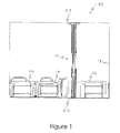
- FIG. 1 there is shown a shower room assembly generally indicated 10.
- the assembly 10 comprises a first shower screen panel 12 which is secured to a wall 14 at one side and at the other side to an elongate pole 16 formed in accordance with the present invention which is described in more detail below.
- a second shower screen panel 18 is fixed and is hingedly connected to a third shower screen panel 20.
- the pole 16 extends from the floor 22 to the ceiling 24 and is fixed thereto.
- the pole 16 can serve as a grab rail for an individual using the shower arrangement and also as a fixed point to which the panels 12, 18 are attached.
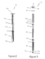
- pole 16 is shown in more detail.
- the pole 16 comprises a lower section 26 which in use is presented to the floor or other base-like structure such as a shower or bath tray.
- a central link section 28 fits telescopically inside the section 26.
- An upper section 30 is also provided and in use the opposite end of the link section 28 fits telescopically inside the section 30.
- the sections 26, 28, 30 comprise the main body of the pole and it will be seen that by adjusting the extent to which the link section 28 slides into the lower and upper sections 26, 30 the overall length of the pole 16 can be adjusted.
- the middle section 28 would usually be slid into the lower section 26 and fixed into position; the upper section 30 would then be slid onto the middle section 28 and then extended to the required length before fixing in position as described in more detail below.
- the lower section 26 is provided with a foot 32 comprising a base plate 34 and an upstanding sidewall 36.
- the sidewall 36 can be pushed inside the lower section 26 so that the end of the section 26 fits flushly onto the base 34.
- the base 34 is provided, in this embodiment, with holes for receiving screws so that the foot 32 can be secured to the ground and thereafter the lower section 26 can be slid onto the sidewall 36.
- top cap 38 is provided at the opposite end of the pole.
- the top cap 38 comprises a top plate 40 from which depends a sidewall 42.
- the top plate 40 is provided with four fixing holes 44 for receiving screws to allow the plate 40 to be fixed to a ceiling.
- the sidewall 42 is dimensioned so that it can be received within the upper end of the upper section 30.
- a generally frustoconical shroud 46 is provided and includes a central aperture 48 which can fit over the upper section 30. After the top cap 38 has been secured to a ceiling the shroud can be slid up to the top of the upper section until it abuts the plate 40 as shown in figure 2 .
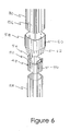
- a friction insert 48 is provided and comprises a sidewall 50 which depends from a flange 52.
- Two friction fins 54 are provided at opposite sides of the flange 52.
- the insert 48 is fitted securely into the upper end of the middle section 28 until the flange 52 abuts against the open end.
- the fins 54 provide friction against the inside of the upper section sidewalls so that adjustment of the relative positions of the middle and upper sections 28, 30 can be made by overcoming the friction, but the sections can be held stably in any relative position.
- the sections 28, 30 are fixed together using a fixing which passes through a moulded countersunk hole 56 in the upper section 30 into the middle section 28.
- a shroud 58 is provided for fitting over the join line between the sections 28, 30 and comprises a generally rectilinear sidewall 60 at one end for engaging the upper section 30 and inwardly inclined sidewall section 62 at the other end for engaging over the middle section 28 as shown in figure 2 .
- a shroud piece 64 identical to the piece 58 is provided at the intersection of the lower and middle sections 26, 28.
- the piece 64 is oppositely orientated to the piece 58 as shown in figure 2 .
- a friction insert/clip is not provided for the intersection between the lower and middle sections 26, 28.
- a further clip is provided.
- a fixing hole 66 is provided in the lower section 26 for receiving a fixing such as a screw. It will be noted that the shroud 64 both covers the intersection between the sections 26, 28 and also covers the fixing hole 66.
Abstract
Description
- The present invention relates generally to a pole and particularly to a floor to ceiling support pole, that is a pole which is generally fixed between upper and lower surfaces in a room.
- Floor to ceiling poles are well known and used for a variety of purposes including as a "grab rail" to facilitate activities, and as a structure to which other structures can be secured. For example, floor to ceiling poles are used extensively in the healthcare industry where the elderly and/or disabled require assistance to move and position themselves. Poles can be provided at appropriate positions within a room either by themselves or in conjunction with other bathroom fixtures such as shower or bath panels.
- Currently poles are supplied as a single fixed length. Because the height of a room in which a pole is required can vary considerably, the pole is cut to size on site and fixed into position. However, the length of such poles causes problems, particularly for transport and packaging.
- The present invention seeks to address the problems with known floor to ceiling poles.
- According to the present invention there is provided a shower screen assembly floor to ceiling support pole, the pole being fixable to one or more shower screen panels so as to form an integral part of a screen assembly and comprising two or more elongate pole sections which are longitudinally telescopic to allow adjustment of the length of the pole.
- By forming the pole so that it is connectable to and forms an integral part of the shower screen assembly it can contribute to the rigidity of the overall screen or panel structure. By providing a telescopic pole it can be packaged and transported in a minimum length state and assembled on site before extending to a required length and fixing into position.
- The pole may comprise three pole sections. For example the pole may comprise an upper, ceiling-engaging section, a lower, floor-engaging section, and a middle, link section.
- Of course three or more pole sections can be provided under the same principle of a telescoping pole. The number of sections could, for example, be selected on the basis of a required maximum section length.
- In embodiments where three or more pole sections are supplied it may be the intermediate, or link sections which telescope inside both of two adjacent sections. Alternatively, for example, the sections may increase or decrease in diameter along the length of the pole.
- The length of each pole section may be substantially the same, or alternatively sections of differing lengths may be preferred for certain situations.
- The length of each pole section may be in the range from 600mm to 900mm, for example in the range of 700mm to 800mm. It may be preferred that the length of the sections is selected so as to be similar to the height of other parts of an assembly. For example, some types of door have a standard height of approximately 750mm and the pole sections can be sized roughly in line with this so that packaging and transport together is made easier.
- The pole sections may have a generally hollow box section or other configuration including one or more flats. The provision of one or more flats makes it easier to attach other parts of an assembly for example screen doors or panels. For example, a box section with rounded corners may be provided. Other sections are possible, including circular, triangular, oval, rectangular and polygonal.
- Once the pole has been extended to a required extent the pole sections may need to be fixed together in addition to fixing at either end. Various fixing means, which may be temporary, permanent or semi-permanent, may be provided.
- In terms of fixing the pole structure as a whole to upper and lower surfaces within a room, a variety of fixing mechanisms may be considered. For example, the ends of the pole could be physically attached to the surfaces, for example, with fixings such as screws or nails. For this purpose the pole may be provided with fixing plates and the like. If permanent fixing is not preferred or possible, then a more temporary fixing, such as by bracing, could be employed. For example, part or a whole of the pole when assembled could be biased towards an extended position and moveable to a retracted position for installation; thereafter the biasing would force the ends of the pole outwards to brace it and hold it in position.
- In order to secure adjacent pole sections together once a required extension has been achieved a variety of fixing methods may be employed. For example, a twist-lock or screw-lock system or a ratchet mechanism. Alternatively fixings, such as screws, may be employed to secure the sections together.
- Inevitably with a telescopic system the pole is not of a uniform width and the transition between wider and narrower sections will be visible, as may fixings for holding sections together. Accordingly, shroud pieces may be provided for covering the region of the join between adjacent pole sections.
- In order to assist with adjustment of the pole, a friction arrangement may be provid ed in which friction is created between adjacent pole sections which can be overcome to allow extension or retraction of sections but which can hold sections stably in position. In other words, the sections are not freely slideable with respect to each other which would make securing them together in a required position much more difficult.
- According to a further aspect there is provided a shower screen assembly incorporating one or more poles as described herein.
- The present invention will now be more particularly described, by way of example, with reference to the accompanying drawings, in which:
-
Figure 1 is a side elevation of a support pole formed according to the present invention shown forming part of a shower screen assembly; -
Figure 2 is a side elevation of the support pole shown infigure 1 ; -
Figure 3 is an exploded side view of the pole offigure 2 ; -
Figure 4 is a magnified view of the upper end of the pole offigure 3 ; -
Figure 5 is a perspective view of the pole offigure 4 ; and -
Figure 6 is an exploded view of the intersection between an upper, ceiling section and a middle, link section of the pole. - Referring first to
figure 1 there is shown a shower room assembly generally indicated 10. Theassembly 10 comprises a firstshower screen panel 12 which is secured to awall 14 at one side and at the other side to anelongate pole 16 formed in accordance with the present invention which is described in more detail below. At the other side of the pole 16 a secondshower screen panel 18 is fixed and is hingedly connected to a thirdshower screen panel 20. - The
pole 16 extends from thefloor 22 to the ceiling 24 and is fixed thereto. Thepole 16 can serve as a grab rail for an individual using the shower arrangement and also as a fixed point to which thepanels - Referring now also to
figures 2 and 3 thepole 16 is shown in more detail. - The
pole 16 comprises alower section 26 which in use is presented to the floor or other base-like structure such as a shower or bath tray. Acentral link section 28 fits telescopically inside thesection 26. Anupper section 30 is also provided and in use the opposite end of thelink section 28 fits telescopically inside thesection 30. - Together the
sections link section 28 slides into the lower andupper sections pole 16 can be adjusted. In practice themiddle section 28 would usually be slid into thelower section 26 and fixed into position; theupper section 30 would then be slid onto themiddle section 28 and then extended to the required length before fixing in position as described in more detail below. - The
lower section 26 is provided with afoot 32 comprising abase plate 34 and anupstanding sidewall 36. Thesidewall 36 can be pushed inside thelower section 26 so that the end of thesection 26 fits flushly onto thebase 34. Thebase 34 is provided, in this embodiment, with holes for receiving screws so that thefoot 32 can be secured to the ground and thereafter thelower section 26 can be slid onto thesidewall 36. - Referring now also to
figures 4 and 5 , at the opposite end of the pole atop cap 38 is provided. - The
top cap 38 comprises atop plate 40 from which depends asidewall 42. Thetop plate 40 is provided with four fixing holes 44 for receiving screws to allow theplate 40 to be fixed to a ceiling. Thesidewall 42 is dimensioned so that it can be received within the upper end of theupper section 30. - A generally
frustoconical shroud 46 is provided and includes acentral aperture 48 which can fit over theupper section 30. After thetop cap 38 has been secured to a ceiling the shroud can be slid up to the top of the upper section until it abuts theplate 40 as shown infigure 2 . - Referring now to
figure 6 the intersection between theupper section 30 and themiddle section 28 is shown. - A
friction insert 48 is provided and comprises asidewall 50 which depends from aflange 52. Twofriction fins 54 are provided at opposite sides of theflange 52. Theinsert 48 is fitted securely into the upper end of themiddle section 28 until theflange 52 abuts against the open end. When themiddle section 28 is pushed into theupper section 30 thefins 54 provide friction against the inside of the upper section sidewalls so that adjustment of the relative positions of the middle andupper sections sections hole 56 in theupper section 30 into themiddle section 28. - A
shroud 58 is provided for fitting over the join line between thesections rectilinear sidewall 60 at one end for engaging theupper section 30 and inwardlyinclined sidewall section 62 at the other end for engaging over themiddle section 28 as shown infigure 2 . - A
shroud piece 64 identical to thepiece 58 is provided at the intersection of the lower andmiddle sections piece 64 is oppositely orientated to thepiece 58 as shown infigure 2 . - In this embodiment a friction insert/clip is not provided for the intersection between the lower and
middle sections - In order to secure the lower and
middle sections lower section 26 for receiving a fixing such as a screw. It will be noted that theshroud 64 both covers the intersection between thesections
Claims (14)
- A shower screen assembly floor to ceiling support pole, the pole being fixable to one or more shower screen panels so as to form an integral part of a screen assembly and comprising two or more elongate pole sections which are longitudinally telescopic to allow adjustment of the length of the pole.
- A pole as claimed in claim 1, in which the pole comprises three pole sections.
- A pole as claimed in any preceding claim, in which the pole comprises an upper, ceiling-engaging section, a lower, floor-engaging section, and a middle, link section.
- A pole as claimed in claim 3, in which the middle section telescopes inside the upper and lower sections.
- A pole as claimed in any preceding claim in which the length of each pole section is substantially the same.
- A pole as claimed in any preceding claim, in which the length of each pole section is in the range 600mm to 900mm.
- A pole as claimed in any preceding claim, in which the length of each pole section is in the range 700mm to 800mm.
- A pole as claimed in any preceding claim, in which the pole sections have a generally box section.
- A pole as claimed in any preceding claim, further comprising one or more shroud pieces for covering the region of the join between adjacent pole sections.
- A pole as claimed in any preceding claim, further comprising friction means for creating friction between adjacent pole sections to adjustably hold the sections in position relative to each other.
- A pole as claimed in any preceding claim, further comprising a top and/or base cap.
- A floor to ceiling pole substantially as hereinbefore described with reference to, and as shown in, the accompanying drawings.
- A shower screen assembly incorporating one or more poles as claims in any preceding claim.
- A shower screen assembly substantially as hereinbefore described with reference to, and as shown in, the accompanying drawings.
Applications Claiming Priority (2)
| Application Number | Priority Date | Filing Date | Title |
|---|---|---|---|
| GB0920706A GB0920706D0 (en) | 2009-11-26 | 2009-11-26 | Floor to ceiling support pole |
| GB201012977A GB2475752B (en) | 2009-11-26 | 2010-08-02 | Floor to ceiling support pole |
Publications (2)
| Publication Number | Publication Date |
|---|---|
| EP2327345A2 true EP2327345A2 (en) | 2011-06-01 |
| EP2327345A3 EP2327345A3 (en) | 2013-04-10 |
Family
ID=41572708
Family Applications (1)
| Application Number | Title | Priority Date | Filing Date |
|---|---|---|---|
| EP10251841.2A Withdrawn EP2327345A3 (en) | 2009-11-26 | 2010-10-22 | Floor to ceiling support pole |
Country Status (2)
| Country | Link |
|---|---|
| EP (1) | EP2327345A3 (en) |
| GB (2) | GB0920706D0 (en) |
Cited By (1)
| Publication number | Priority date | Publication date | Assignee | Title |
|---|---|---|---|---|
| WO2013120138A1 (en) * | 2012-02-17 | 2013-08-22 | Lifting Point Pty Ltd | Height adjustable column for a shipping container building structure |
Family Cites Families (12)
| Publication number | Priority date | Publication date | Assignee | Title |
|---|---|---|---|---|
| US2465853A (en) * | 1948-06-10 | 1949-03-29 | Jr Simon E Dalton | Bathtub with contained shower curtain |
| DE1907229A1 (en) * | 1969-02-13 | 1970-09-03 | Karl Deimer | Bathtub accessory |
| DE2452344A1 (en) * | 1974-11-05 | 1976-05-06 | Ottmar Bitsch | Easily mounted lining panels for attachment to bath tubs - fit into tension holder allowing tiling etc to be completed |
| US4158896A (en) * | 1976-02-06 | 1979-06-26 | Farkas Julius J | Four-sided shower curtain rod frame assembly |
| US4498204A (en) * | 1983-09-21 | 1985-02-12 | Warner Stanley H | Adjustable position physical support system |
| US4975992A (en) * | 1989-10-30 | 1990-12-11 | James Patterson | Portable shower stall |
| DE29504518U1 (en) * | 1995-03-22 | 1995-05-04 | Altura Leiden Holding | Shower partition |
| DE20308682U1 (en) * | 2003-05-27 | 2003-10-23 | Senger Ingrid | Flexible shower screen is made from acrylic glass and hangs on curtain rings passed through holes in its upper edge from telescopic rail |
| DE202006017765U1 (en) * | 2006-11-22 | 2007-01-11 | Wenko-Wenselaar Gmbh & Co. Kg | Clamp for mounting on telescopic floor-to-ceiling bars in bathrooms is made up of two curved sections, one of which has ribs along its edges which slide into grooved profiles on other, allowing sections to be fitted together axially |
| WO2009023391A1 (en) * | 2007-08-14 | 2009-02-19 | Matthew Kestian | Self-supporting shower head system |
| CN201409853Y (en) * | 2009-06-12 | 2010-02-24 | 王成军 | Folding type warm bathroom |
| DE202010001030U1 (en) * | 2010-01-15 | 2010-05-06 | Schulte Duschkabinenbau Gmbh & Co. Kg | shower enclosure |
-
2009
- 2009-11-26 GB GB0920706A patent/GB0920706D0/en not_active Ceased
-
2010
- 2010-08-02 GB GB201012977A patent/GB2475752B/en active Active
- 2010-10-22 EP EP10251841.2A patent/EP2327345A3/en not_active Withdrawn
Non-Patent Citations (1)
| Title |
|---|
| None |
Cited By (3)
| Publication number | Priority date | Publication date | Assignee | Title |
|---|---|---|---|---|
| WO2013120138A1 (en) * | 2012-02-17 | 2013-08-22 | Lifting Point Pty Ltd | Height adjustable column for a shipping container building structure |
| US9067721B2 (en) | 2012-02-17 | 2015-06-30 | Lifting Point Pty Ltd. | Height adjustable shipping container |
| US9248957B2 (en) | 2012-02-17 | 2016-02-02 | Lifting Point Pty Ltd | Height adjustable column for a shipping container building structure |
Also Published As
| Publication number | Publication date |
|---|---|
| EP2327345A3 (en) | 2013-04-10 |
| GB201012977D0 (en) | 2010-09-15 |
| GB0920706D0 (en) | 2010-01-13 |
| GB2475752A (en) | 2011-06-01 |
| GB2475752B (en) | 2013-02-27 |
Similar Documents
| Publication | Publication Date | Title |
|---|---|---|
| US9627867B2 (en) | Mounting brace assembly for mounting an electrical box | |
| US10104964B2 (en) | Supporting an object at a window of a building by applying opposing forces to an interior surface and an exterior surface of the building | |
| US20150028025A1 (en) | Height adjustable column for a shipping container building structure | |
| US20160166118A1 (en) | Shower storage and assist assembly | |
| AU2005262951A1 (en) | Electronic device mounting bracket for a horizontal support | |
| WO2007139717A3 (en) | Versatile telescopic door hinge hanger | |
| US9249568B2 (en) | Portable, temporary wall system | |
| US20110079698A1 (en) | brace | |
| US20150060616A1 (en) | Adjustable television nook mount | |
| US10094509B2 (en) | Building components and structures | |
| EP2327345A2 (en) | Floor to ceiling support pole | |
| US20120018604A1 (en) | Bracket Having Overhanging Support Elements For Supporting An Electrical Box | |
| AU2008100267A4 (en) | A brace | |
| EP3473785A1 (en) | Telescopic mast | |
| CN212583351U (en) | Independent supporting structure with retractable support | |
| US20110252729A1 (en) | Adjustable wall support system and method | |
| US20130075555A1 (en) | Support Bracket For Supporting An Electrical Box | |
| US10436383B1 (en) | Supporting an object at a window of a building using an adjustable support apparatus | |
| CN212535198U (en) | Tripod independent support frame body | |
| US7918423B2 (en) | Mobile antenna support | |
| US20130155679A1 (en) | Handrail system | |
| GB2399833A (en) | Telescopic strut for use e.g. with stud partitions | |
| US20020139072A1 (en) | Curved temporary display wall | |
| CA2812107A1 (en) | A fly form table with adjustable legs | |
| US20190112153A1 (en) | Elevator shaft access safety device and method of using the same |
Legal Events
| Date | Code | Title | Description |
|---|---|---|---|
| PUAI | Public reference made under article 153(3) epc to a published international application that has entered the european phase |
Free format text: ORIGINAL CODE: 0009012 |
|
| AK | Designated contracting states |
Kind code of ref document: A2 Designated state(s): AL AT BE BG CH CY CZ DE DK EE ES FI FR GB GR HR HU IE IS IT LI LT LU LV MC MK MT NL NO PL PT RO RS SE SI SK SM TR |
|
| AX | Request for extension of the european patent |
Extension state: BA ME |
|
| RAP1 | Party data changed (applicant data changed or rights of an application transferred) |
Owner name: IMPEY SHOWERS LTD |
|
| PUAL | Search report despatched |
Free format text: ORIGINAL CODE: 0009013 |
|
| AK | Designated contracting states |
Kind code of ref document: A3 Designated state(s): AL AT BE BG CH CY CZ DE DK EE ES FI FR GB GR HR HU IE IS IT LI LT LU LV MC MK MT NL NO PL PT RO RS SE SI SK SM TR |
|
| AX | Request for extension of the european patent |
Extension state: BA ME |
|
| RIC1 | Information provided on ipc code assigned before grant |
Ipc: A47K 3/30 20060101AFI20130301BHEP |
|
| STAA | Information on the status of an ep patent application or granted ep patent |
Free format text: STATUS: THE APPLICATION IS DEEMED TO BE WITHDRAWN |
|
| 18D | Application deemed to be withdrawn |
Effective date: 20131011 |