EP2327082B1 - A motor operator for switchgear for mains power distribution systems - Google Patents
A motor operator for switchgear for mains power distribution systems Download PDFInfo
- Publication number
- EP2327082B1 EP2327082B1 EP09740045.1A EP09740045A EP2327082B1 EP 2327082 B1 EP2327082 B1 EP 2327082B1 EP 09740045 A EP09740045 A EP 09740045A EP 2327082 B1 EP2327082 B1 EP 2327082B1
- Authority
- EP
- European Patent Office
- Prior art keywords
- worm wheel
- switchgear
- motor operator
- worm
- adapter
- Prior art date
- Legal status (The legal status is an assumption and is not a legal conclusion. Google has not performed a legal analysis and makes no representation as to the accuracy of the status listed.)
- Not-in-force
Links
Images


Classifications
-
- H—ELECTRICITY
- H01—ELECTRIC ELEMENTS
- H01H—ELECTRIC SWITCHES; RELAYS; SELECTORS; EMERGENCY PROTECTIVE DEVICES
- H01H3/00—Mechanisms for operating contacts
- H01H3/22—Power arrangements internal to the switch for operating the driving mechanism
- H01H3/227—Interlocked hand- and power-operating mechanisms
-
- H—ELECTRICITY
- H01—ELECTRIC ELEMENTS
- H01H—ELECTRIC SWITCHES; RELAYS; SELECTORS; EMERGENCY PROTECTIVE DEVICES
- H01H3/00—Mechanisms for operating contacts
- H01H3/22—Power arrangements internal to the switch for operating the driving mechanism
- H01H3/26—Power arrangements internal to the switch for operating the driving mechanism using dynamo-electric motor
- H01H2003/266—Power arrangements internal to the switch for operating the driving mechanism using dynamo-electric motor having control circuits for motor operating switches, e.g. controlling the opening or closing speed of the contacts
Description
- The invention relates to a motor operator as stated in the preamble of claim 1 for opening and closing a mains switch of switchgear in mains power distribution systems such as public medium high voltage distribution systems.
- Motor operators for switchgears are known see e.g.
US 4,804,809 to Chance Co. AB ,US 5,254,814 to Chance Co. AB,WO 2008/052548 A1 to Linak A/S, andWO 2006/106364 to Viserge Ltd. These motor operators are separate units for mounting in front of switchgears as indicated inUS 4,804,809 to Chance Co. AB andWO 2006/106364 to Viserge Ltd. The motor operators are contained in a weather and vandal proof enclosure which is rather voluminous. Further, it should be fully operable under all weather conditions and operate in a reliable manner. The front surface of the switchgear is exposed to the open air which is why the overall size of the motor operator is of no significant importance. However, there are also switchgears where the front surface is covered by a front door to protect the front surface of the switchgear and to prevent unauthorized access to the switchgear. The front door restricts the space available for a motor operator and not only that, it also complicates the mounting as it is prohibited to make bores and weldings in the switchgear cabinet. - It should also be taken into account that the motor operator may be activated either locally or remotely to open and close the mains switch of the switchgear. However, as a safety precaution it should also be possible to operate the switchgear manually, e.g. in case of failure of the motor operator. This also complicates the construction of the motor operator and contributes to the overall size.
-
WO97/16660 - It is an object of the present invention to provide a motor operator, which is easy to mount and could be mounted on switchgear from various manufactures of switchgear and which to a great extend is nonintrusive and vandal proof. Another object of the invention is to provide a solution that takes up less space and thus can be mounted retrofit directly in the accessible part of the housing of the switchgear itself.
- According to the invention this is accomplished in that the motor operator further comprises an adapter fixedly connected to the second end of the connection shaft and where a recess in the worm wheel is designed for receiving the adapter in a rotational interlocking manner. Additionally, the worm wheel and the worm is embedded in a separate worm gear housing and a driven end of the worm is accessible on the housing, preferably on a side surface for connection with the drive shaft of the motor. In this way, the overall dimension and especially the thickness of the housing can be kept very small not taking up much space in the front of the switchgear. The connection between the operating shaft of the mains switch and the motor operator is obtained by plugging the adapter into the recess of the worm wheel in a non-rotational interlocking manner, so that the adapter will be carried along in the rotational movements of the worm wheel. The worm wheel is rotated in its bearing in the worm gear housing by the worm which has a driven end to be connected to the electric motor. The electric motor could be fitted directly to the worm gear housing with the motor axle connected directly to the driven end of the worm. Since an electric motor is rather voluminous it could be advantageous to move the motor a distance away from the worm gear housing. In some switchgear cabinets quite a lot of space is left on top of the sealed compartment of the switch, where it in a preferred embodiment would be convenient to mount the electrical motor in a separate control box also containing various electronic equipments. On the other hand the motor and the various electronic equipments could also be located in separate housings. The connection from the motor to the driven end of the worm, could be a universal transmission, such as a cardan drive however, a flexible shaft is preferred. The flexible shaft also has the benefit that initial or peak forces to a certain degree are absorbed by the flexible shaft.
- In an embodiment the recess in the worm wheel is a through hole aligned with a through hole in the worm gear housing for receiving the adapter bearing the connection shaft. The rotational interlocking of the adapter in the worm wheel so the adapter is carried along with the movements of the worm wheel could be carried out in various manners. The hole could e.g. have a none-circular cross section, e.g. hexagonal or have at least one straight wall part. On the other hand the hole could also be circular, but then with means for interlocking, such as retractable pins resting in holes on the other part. In a preferred embodiment the means for rotational interlocking of the adapter in the worm wheel comprises at least one key and one keyway and that the key could be pushed forward from a retracted position to an expelled position in engagement with the keyway preferable by means of a wrench for manually operation of the switchgear. In another embodiment the adapter is located in a circular recess in the worm wheel and is connected to this by a coupling such as a ball coupling.
- The adapter or the entire worm gear housing has to be removed if a manual switching of the switchgear is necessary, since it will not be possible to manually drive the worm wheel with the worm and the motor, because of the mechanisms self-locking qualities. When the adapter shaft is removed, the opening in the worm wheel uncovers the operating shaft of the switchgear which can then be operated manually by inserting and using a handle tool suited for the purpose.
- Conveniently, the worm gear housing will be equipped with a sensor to sense if the adapter is placed in position in the housing in relation to the worm wheel in a rotational interlocking manner. A receiver to receive the signal provides the signal to a control for monitoring the state of operation of the switchgear.
- In a preferred embodiment, the motor operator includes a sensor to determine the rotation angle of the worm wheel.
- The information on the rotation angle of the worm wheel can be logged together with the information on the switching transition of the mains switch contacts, and later be used to determine the position of the mains switch contacts. To use a sensor to determine the angle of the worm wheel and thus also the operating shaft of the mains switch is appreciated, since the angle for when a switching transition is accomplished varies from switchgear to switchgear, not only when it comes to different manufactures, but also of the same type and brand. A procedure of convenience when equipping and installing a motor operator on a switchgear will be to perform a learning session, where as a first action the motor operator will force the mains switch from an open to a closed state, and accordingly store the angle on which the switching transition is activated. After that, a second action must be performed using the motor operator to force the mains switch from the closed state and back to the open state, and accordingly store the angle on which the switching transition is activated. From the stored angles it is possible to map at least three different angle scales that picture the mains switch contacts in the open state, the mains switch contacts in the closed state and a not determined state in between the two well-defined states where the motor operator is performing a switching transition of the switchgear. If the angle measurement stays in the scale where the state of the switchgear is not defined in a long period, an alarm should be issued, since it seems to indicate a failure of the motor operator. It would be appreciated if the control could maintain a log of last known stable connection to give a hint of the state of the switchgear in case of a faulty motor operator.
- In some cases there could be a need to perform a manual operation of the switchgear. It could be in the case of a faulty motor operator, or when service personnel are on site, and wishes to manually operate the switchgear and perform service on the transmission line. In that case the transmission line has to be connected to the earth potential by operating the earth switch. This action can only be performed when the switchgear state is open and the handle tool for the mains switch contacts is pulled out. This means that not only the operating tool has to be pulled out, but also if the tool is substituted by the adapter inserted in the worm wheel, it also has to be pulled out. For operating the switchgear operating shaft, a spring has to be suppressed, before the power of the spring is released in the transition operation of the mains switch contacts. Removing the adapter or the entire worm gear housing when the spring is not in its relaxed state will be a difficult task and would lead to a sudden release of the spring and rotation of the operating shaft, and should be avoided. To insert the adapter shaft in position back in the worm wheel will be impossible since the means for keeping the adapter shaft in a rotational interlocking manner will not be positioned to receive the adapter shaft. Anyhow, the problem can be solved by adding another two stored set points with basis in the rotation angle of the worm wheel to reflect the angle of the rotation of the worm wheel corresponding to the positions possible to insert the adapter shaft when the spring is in its relaxed state. These set points being calibrated when installing the motor operator as part of the installation procedure of the motor operator. A procedure of convenience for the storing of the set points could be performed by at a first action manually to operate the switch gear to the open state and accordingly manually drive the motor operator until it is possible to insert the adapter and then store the angle measurement as an expression of the relaxed state of the spring when the switchgear is in its open state. As a second action unplugging the adapter and manually operating the switch gear to the closed state and accordingly manually drive the motor operator until it is possible to insert the adapter and then store the angle measurement as an expression of the relaxed state of the spring when the switch gear is in its closed state. After a manual operation, it will then be possible to automatically force the motor drive to automatically rotate the worm wheel into the angle positions where it is again possible to insert or remove the adapter. It has to be understood that the manual operations performed could be substituted with motor driven operations. Then the set points have to be made when it is possible to take out the adapter of the work wheel.
- Equipping or connecting the motor operator with a sensor to detect earthing mode will be an advantage since the state of the switch gear can then be monitored from remote via the control system. For more information on a control and surveying system for a switch gear reference is made to
WO 2008/052550 A1 to Linak A/S which hereby is made part of the present application. The procedures and features related to controlling the motor operator described in this document will be understood to be possible to implement and carry out in a control unit as referred to. Also the angle detection and stored set points and automated processes are understood to be carried out by the control. - In a preferred embodiment, the motor drives and the control system are arranged in a shared housing, and will benefit from being a compact and easy to install unit which is sealed and protected against the environment. An appreciated type of housing is the type of modular housing specified in
WO 2008/052549 A1 Linak A/S which hereby is made part of the present application. The control system for the motor operator in form of an electronic circuitry on a printed circuit board is in an expedient way mounted in one end of the cabinet. In connection with the printed circuit board are sockets for receiving the energy to drive the motors and connections for interfacing with the control system from remote, to transfer data or to directly control the switchgear. The sockets can be placed directly on the printed circuit board and preferably arranged in a way where they fit premade holes for inserting the connectors through the walls of the cabinet. Of course this should be done in a way with respect to keeping the sealing of the cabinet intact, by adding protective means like o-rings on the connectors which go into connector ports to fit into the connection sockets. The motor drives can be placed side by side in the distant end of the cabinet, the output axles protruding out of the end of the cabinet in order to easily mount the flexible cable for connection with the driven worm on the rotary gear mechanism. - Further the system as described is advantageous since it can be mounted retrofit, nonintrusive on a switch gear with the use of mounting brackets fitted on the outer framework of the switch gear or at already present and available mounting parts of the switchgear housing. Reference is made to
WO 2008/052549 A1 Linak A/S for more information as how to mount a motor operator retrofit nonintrusive on a switch gear. Said document is hereby made a part of the present application. - An embodiment of the invention will be described in the following with reference to the accompanying drawing.
-
-
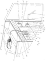
Fig. 1 shows a perspective view of a top, front part of a switchgear furnished with a motor operator, -
Fig. 2 shows a further embodiment of a motor operator for operating two switches of a switchgear, -
Fig. 3 showing an overview of the arrangement of the control box, -
Fig. 4 shows a further embodiment of the control box which includes both the control and the motor drives, -
Fig. 5 shows an exploded view of a control box, -
Fig. 6 shows an embodiment of the motor operator seen from the front surface, -
Fig. 7 shows a longitudinal section after line A-A inFig. 6 , -
Fig. 8 shows a cross section after line B-B inFig. 6 , and -
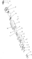
Fig. 9 shows an exploded view of the motor operator inFigs. 6-8 . - In
Fig. 1 is shown a top, front part of a switchgear 1 comprising aclosed cabinet 2 inside which is located two sets of mains switches. In front of thecabinet 2 there is a hingeddoor 3 covering afront surface 4 of thecabinet 2. Each mains switch has an operating shaft with acoupling part 5,5' accessible through ahole 6,6' on thefront surface 4 of the cabinet. The operating shaft could be operated manually by awrench 7 having an end designed as acoupling part 8 for engagement with thecoupling part 5 of the operating shaft. Thecoupling part 5 is the end part of the shaft having a through pin. Thecoupling part 8 of the wrench is tube shaped having two aligned notches in the tube wall so it could be placed over the end of the operating shaft such that the end of the through pin thereof is received in the notches in a rotational interlocking manner. When the mains switch is in an open position it is possible to earthen the switchgear. The operating shaft for the earthing has an identical coupling as the operating shaft for the mains switch so thewrench 7 could be used for the earthing. For security reasons the earthing should always be performed manually. The operating shaft for the earthing could be reached through the hole 9,9'. - The operating shaft for the mains switch could be operated by a
motor operator 10 which comprises aworm gear housing 11 mounted on a mountingbracket 12 attached to a horizontaltransverse beam 13 mounted on the switchgear. Further, the motor operator comprises anelectric motor 14 located remotely in a separate control box on top of theswitchgear cabinet 2. Aflexible connection shaft 15 interconnects themotor 14 and theworm gear housing 11. - In the
worm gear housing 11 is embedded aworm wheel 16 having a collar at a front end 17 of thehousing 11. Also in theworm gear housing 11 is embedded a worm, adriven end 18 of which is accessible on asidewall 19 of thehousing 11 for connection with theflexible connection 15 to the drive axle of themotor 14. Theworm wheel 16 has a recess in the nature of a throughhole 20 for receiving anadapter 21 with aconnection shaft 22. Afirst end 23 of theconnection shaft 22 is designed as a coupling part 8' like thecoupling part 8 of thewrench 7 so it could operate the operating shaft of the mains switch. Theadapter 21 has on its side a key 23 and thehole 20 of theworm wheel 16 has amating keyway 24 so the adapter could be received in the throughhole 20 of theworm wheel 16 in a rotational interlocking manner. The key 23 has a certain clearance in thekeyway 24 to prevent the forces from the spring mechanism to be transferred to theworm wheel 16. - The key 23 is a separate element received in a groove in the
adapter 21 and could from a retracted position be pushed out when theadapter 21 is located in the throughhole 20 of theworm wheel 16 for engagement with thekeyway 24 such that theadapter 21 is locked also in its lateral position to secure a correct position in theworm wheel 16 but also in relation to thecoupling part 5,5' of the operation shaft of the mains switch. Most important the locking secures that the coupling part 8' of theconnection shaft 15 of theadapter 21 in fact is in engagement with the operating shaft of the mains switches when theadapter 21 is correctly located in theworm wheel 16. The key 24 is resting on an eccentric in the adapter, which eccentric could be operated by means of thewrench 7 in thehole 25 at the front end of theadapter 21. - Accordingly, it would be understood that the mains switch could be operated by the motor operator when the
adapter 21 has been correctly located in theworm wheel 16 and at the same time earthing is prevented. Having the need for operating the switchgear manually, theadapter 21 is removed and thewrench 7 could be inserted through the through hole in theworm wheel 16 and the rear end of the worm gear housing. - All though not shown it should be noted that a similar motor operator is mounted in connection with the other operating shaft of the switchgear the coupling part of which is indicated by 5'.
- In a further embodiment, as shown in
fig. 2 , the switchgear is equipped with a motor operator comprising two worm gear housings and acontrol box 26 containing two individual motors for the worm gears and the electronic control system for the control of the motor operator. Thecontrol box 26 is located in the compartment over the switchgear, a distance from the operating shafts of the switchgear. - As can be seen from
fig. 3 , showing an overview of the arrangement of thecontrol box 26, the control box contains the control system and themotors circuit board 29 with the power electronics to drive themotors controller 30, preferably in the form of a microcontroller, which also features the interfacing with the overall control system of the switchgear. Equipped on the printedcircuit board 29 areconnectors 31 for attaching a supply of power to the system and for multipurpose inputs and outputs. Theconnectors 31 on the printed circuit board are placed adjacent to the wall of the cabinet of thecontrol box 26 for easy plugging of power supply andinterface cables 32 directly into the sockets through holes made from outside of the cabinet. One of the inputs is for receiving a potentiometer for determining the angle rotation of the operating shaft of the switchgear, which could be substituted by a magnetically based arrangement using a Hall-sensor. Another input in the form of a logical input to indicate if the adapter is plugged correctly into the worm wheel or not, is available. An input/output is also used for a multidirectional data bus for interfacing data with a remote control. For connecting themotors connectors motors flexible axles 10 mounted to the drivenend 18 on the worm. -
Fig. 4 shows a further embodiment of the control box which includes both the control and themotors 27. The housing of the control box consists of an elongated extrudedaluminum tube 35, with a front andrear cover screws 38, in each end of the tube. In thetube 35 is internally on both sidewalls formed a slot for fixing and positioning a printedcircuit board 29 for the control system in its position in thecontrol box 26. Similarly the slot can be used for fixing a mounting frame for mounting the motor drives 27, 28 in the control box. In a first end of the control box housing the motor axles are protruding andflexible axles 15 are mounted to those motor axles. In the distant second end of the housing the power- andinterface cables 32 are connected. In a preferred embodiment the connectors are plugged directly into connection sockets on the printed circuit board, through ports made in theenclosure 35, preferably in therear cover 37. It will be appreciated that the ports are equipped with means for protecting thecontrol box 26 against intruding water or dust, in order to maintain a reliable functioning of the motor drive. - In
Fig. 5 is an exploded view of acontrol box 26 similar to that shown inFigs. 3-4 and the same reference numerals are used for the same components. Themotors output shaft 28" there is a first part of a claw coupling 38a in engagement with a second part of theclaw coupling 38b. The second part of the claw coupling is having anoutput shaft 38b' in the nature of a spline for aconnector 39 for connection of the end of theflexible shaft 15. Themotors front element 40 by means of screws and theclaw coupling 38a,38b is resting in an aperture 40',40'. The outer surface of thefront element 40 is in a snug fitting manner mating the upper part of the internal cross section of thetubular housing 35. Thefront element 40 is attached to thefront cover 36 by means of screws and thefront element 40 is again fixedly secured to the tubular housing by means of screws.Reference numeral 41 is a gasket located between the end of thetubular housing 35 and thefront cover 36. Thefront cover 40 is supplied with a printedsheet 42 on which is printed various user information. Theconnectors 39 for theflexible shafts 15 are resting in an aperture in thefront cover 36. At the front end of thehousing 35 there is a further circuit board 29a furnished withconnectors 31 for receiving cables. The sockets 32' of the cables is retained by alocking beam 42 attached by screws to the front cover. The same is true for theinterfaces cables 32 at the rear end of thecontrol box 26. At the rearend reference numeral 43 also designates a gasket between therear cover 37 and the tube of thehousing 35. - In
Figs. 6-9 is shown a further embodiment of the motor operator or more specifically the operator unit with aworm gear housing 44 comprising acompartment 45 of die cast metal and afront cover 46 attached to thecompartment 45 by means ofscrews 47 and with angasket 48 for water and dust proofing purposes. In thecompartment 45 there is embedded aworm 49 having at both end a needle andaxial bearing spring 53. The ends of the shaft of theworm 49 are designed with aspline connection 54 for receiving an end of theflexible shaft 15. The ends of theworm 49 are available through anaperture 55 in the sidewall of thecompartment 45. Theapertures 55 can be closed by means of aplug 56. Accordingly one may freely choose to connect theflexible shaft 15 at either end of theworm 49. Theworm 49 is in mesh with aworm wheel 57 also situated in thecompartment 45 and located between two slidingring elements adapter 60 is with a circular plate element 60' received in arecess 61 in theworm wheel 57. Theadapter 60 is having aconnection shaft 22 similar to the connection shaft of the embodiment shown inFig. 1 and is therefore given the same reference numeral. At the opposite end of theconnection shaft 22 theadapter 60 is having a circular portion with anexternal tooting 62 in mesh with an internal tooting of aring 63 also located in therecess 61 of theworm wheel 57. On top of thering 63 there is awasher 64. Thewasher 64 is kept in place by means of a retainingelement 65 having a circular plate shaped portion 65' and astem 65" with external threads which could be screwed into ahole 67 with internal threads in thecentral portion 62 of theadapter 60. The retainingelement 65 is dust and water proof by means of an O-ring 67 located in a groove in the side wall of the plate shaped portion 65' of the retaining element. On top of the retainingelement 65 there is a printedsheet 68 bearing user information likewise thefront cover 46 is furnished with a printedsheet 68 also bearing user information. In a hole in the circular plate member 60' there is located a spring loadedball 69 running on apotentiometer 70 connected to anelectronic print 71. Thepotentiometer 70 can by means of acable 71 be connected to the control box. The plug of the cable could be secured against unintentional unplugging by means of a locking plate 73 attached by screws to thecompartment 45. Thepotentiometer 70 is determining the angle position of the connection shaft as previously described. Theconnection shaft 21 is via the threads on thecentral portion 62 of theadapter 60 meshing with the internal threads of thering 63 in engagement with theworm wheel 57 by means of a number ofballs 74 resting in throughholes 75 in thering 63 andapertures 76 in therecess 61 of theworm wheel 57. Theballs 74 are kept in their position by means of thewasher 64 and the retainingelement 65. The switches of a switch gear are as previously mentioned spring loaded for instantaneous switching of the switches. In case something goes wrong and the switch for some reason or another is caught in an intermediate position then the operating shaft of the switch is under a heavy spring load which is conveyed to the worm gear which is self-locking. To dismount the operator unit, i.e. theworm gear housing 44 it is therefore necessary to release the worm gear, which is done by unscrewing theretainer element 65 by means of an Allen key inserted into thehexagonal hole 77. When theretainer element 65 is screwed outwards then space is admitted to theballs 74 to move out of engagement with theworm wheel 57 and the operator unit could then dismounted. Before remounting the operator unit then the position of theconnection shaft 21 should be reset. It would be obvious that also this embodiment could easily by adapted to switchgears with various coupling parts of the operating shaft of a switchgear simply by replacing theadapter 21 with a mating coupling part. Moreover, this embodiment could also be used for switchgear where the operating unit, i.e. theworm gear housing 45 is mounted in a distance from the coupling part of the operating shaft simply by employing an intermediate shaft furnished with respective coupling part in each end. - Although the motor operator has been described in connection with a switchgear having a front door, it would be understood that it could also be used in connection with switchgear where the front surface is exposed to the open air.
Claims (12)
- A motor operator for switchgear (1) for mains power distribution system,
the switchgear (1) comprising:a cabinet (2) with at least one operating shaft for at least one mains switch located inside the cabinet, said operating shaft having a coupling part (5,5')accessible on a front surface (4) of the cabinet and said operating shaft being rotatable between at least two positions namely corresponding to a closed and an open position of the mains switchthe motor operator (10) comprising:a separate worm gear housing having a front surface and rear surface a rotatable connection shaft (22) with a first and second end said first end being designed for engagement with the coupling part (5,5') of the operating shaft of the switchgear (1), said connection shaft (22) rests in a hole in the front surface of the separate worm gear housing,an electric motor (27,28),and where there in the front surface of the housing is an opening for the connection shaft (22),a worm gear with a worm and a worm wheel (16) said worm being in driving connection with the motor for rotating the connection shaft (22) wherein the worm wheel (16,57) and the worm (49) are embedded in a separate worm gear housing (11,44), a drive end
of the worm (49) is accessible from the outside of the housing (11,44) for connection with the motor (27,28), and an adapter (21,60) is fixedly connected to the second end of the connection shaft (22), characterized in thatthe separate worm gear housing comprises a side surface connecting the front surface and the rear surface, and in thatthere is a recess (20,61) in the worm wheel (14,57) for rotational interlocking connection of the adapter with the worm wheel. - A motor operator according to claim 1, characte rized in that the connection between the drive shaft of the motor (27,28) and a driven end of the worm (49) is a flexible shaft (15).
- A motor operator according to claim 1, characte rized in that the rotational interlocking connection between the adapter and the worm wheel is a releasable coupling, preferably a ball coupling (74).
- A motor operator according to claim 1, characte rized in that the recess in the worm wheel (16) is a through hole (20) designed for or having means for receiving the adapter (21) in a rotational interlocking manner and that there is an opening in the front surface of the housing for exposing the recess in the worm wheel for receiving the adapter.
- A motor operator according to claim 4, characte rized in that the means for rotational interlocking of the adapter (21) in the worm wheel (16) comprises at least one key (23) and one keyway (24) and that the key could be pushed forward from an retracted position to an expelled position in engagement with the keyway preferable by means of a wrench for manually operation of the switchgear.
- A motor operator according to claim 1, characte rized in that the motor operator includes a sensor to determine if the adapter is received in the recess or through a hole of the worm wheel in a rotational interlocking manner.
- A motor operator according to claim 1, characte rized in that the motor operator includes a sensor (70) to determine the angle of rotation of the worm wheel.
- A motor operator according to claim 1, characte rized in that the motor operator includes a sensor to determine if a lock for at least one earthing contact of the switchgear is in a locked or an unlocked position.
- A motor operator according to claim 1, characte rized in that the motor operator includes a sensor to determine whether the earthing contact is in an open or a closed position.
- A method for carrying out a learning cycle of the motor operator of claim 1 to match a measurement of the rotation angle of the worm wheel with the state of the switchgear, including a first set point corresponding to the closed state of the switchgear and including a second set point corresponding to the open state of the switchgear,
where the first set point is the measurement of the rotation angle of the worm wheel stored just when the transition from the open to closed state of the mains switch is performed, and
where the second set point is the measurement of the rotation angle of the worm wheel stored just when the transition from the closed to open state of the mains switch is performed,
the three scales for rotation angle measurement being angles over the first set point, angles under the second set point and angles in between the set points are reflecting a closed and an open state of the mains switch and a scale in between where the read out cannot be trusted. - A method for carrying out a learning cycle to match a measurement of the rotation angle of the worm wheel with the closed and open state of the mains switch where a rotational spring force on the operating shaft is relaxed,
the first set point being the rotation angle measurement where the mains switch is in the closed position and the spring is relaxed and the connection shaft of the adapter is free to be removed or inserted fitting its rotational interlocking means in the worm wheel and
the second set point being the rotation angle measurement where the mains switch is in the open position and the spring is relaxed and the adapter with the connection shaft is free to be removed or inserted fitting its rotational interlocking means in the worm wheel. - A method for adapting the rotation angle of the worm wheel to correspond to the actual state of the mains switch, where the motor operator is forced to rotate the worm wheel to match the stored angles corresponding to the first and second set point of method according to claim 10 or 11.
Applications Claiming Priority (3)
| Application Number | Priority Date | Filing Date | Title |
|---|---|---|---|
| DKPA200801322 | 2008-09-24 | ||
| DKPA200801604 | 2008-11-17 | ||
| PCT/DK2009/000211 WO2010034313A2 (en) | 2008-09-24 | 2009-09-24 | A motor operator for switchgear for mains power distribution systems |
Publications (2)
| Publication Number | Publication Date |
|---|---|
| EP2327082A2 EP2327082A2 (en) | 2011-06-01 |
| EP2327082B1 true EP2327082B1 (en) | 2017-06-14 |
Family
ID=41402325
Family Applications (1)
| Application Number | Title | Priority Date | Filing Date |
|---|---|---|---|
| EP09740045.1A Not-in-force EP2327082B1 (en) | 2008-09-24 | 2009-09-24 | A motor operator for switchgear for mains power distribution systems |
Country Status (5)
| Country | Link |
|---|---|
| US (1) | US8890017B2 (en) |
| EP (1) | EP2327082B1 (en) |
| CN (1) | CN102165547B (en) |
| AU (1) | AU2009295365A1 (en) |
| WO (1) | WO2010034313A2 (en) |
Families Citing this family (8)
| Publication number | Priority date | Publication date | Assignee | Title |
|---|---|---|---|---|
| DK2080206T3 (en) * | 2006-10-31 | 2012-02-13 | Linak As | An engine unit for switchgear for power supply systems |
| US8325078B1 (en) * | 2009-08-10 | 2012-12-04 | Finley Lee Ledbetter | Remote switch operator controller |
| WO2012163354A1 (en) | 2011-05-31 | 2012-12-06 | Linak A/S | Actuator |
| DE102011078575B4 (en) | 2011-07-04 | 2013-01-31 | Kries-Energietechnik Gmbh & Co.Kg | Device for load switch operation |
| US9876335B2 (en) | 2015-08-27 | 2018-01-23 | Abb Schweiz Ag | System, method and device for racking circuit breakers |
| CN108346532B (en) * | 2018-04-28 | 2023-09-19 | 无锡市新一代电力电器有限公司 | Flexible interlocking system of switch cabinet |
| CN112670118B (en) * | 2020-12-04 | 2022-09-30 | 河南平高通用电气有限公司 | Looped netowrk is ground connection interlocking device and looped netowrk cabinet for cabinet |
| GB2609423A (en) * | 2021-07-29 | 2023-02-08 | Nortech Man Ltd | Switch gear controller |
Family Cites Families (11)
| Publication number | Priority date | Publication date | Assignee | Title |
|---|---|---|---|---|
| US4804809A (en) | 1987-10-26 | 1989-02-14 | A. B. Chance Company | Motor operator for padmount switchgear |
| US5254814A (en) | 1992-08-11 | 1993-10-19 | A.B. Chance Company | Motor operator connecting member for padmount switchgear |
| FR2735794B1 (en) * | 1995-06-26 | 1997-09-19 | Elysees Balzac Financiere | PROCESS FOR THE PREPARATION OF A MIXTURE OF CELLULOSIC FIBERS AND MICROFIBERS |
| NO307903B1 (en) * | 1995-11-01 | 2000-06-13 | Abb Kraft As | Transmission device |
| US5895987A (en) * | 1997-12-22 | 1999-04-20 | S&C Electric Company | Power operator for switchgear with manual features |
| GB0507119D0 (en) | 2005-04-08 | 2005-05-11 | Viserge Ltd | Improvements relating to switch operation in electrical power distribution networks |
| AU2007315383B2 (en) * | 2006-10-31 | 2011-06-09 | Linak A/S | A motor operator for switchgear for mains power distribution systems |
| EP2087496A1 (en) | 2006-10-31 | 2009-08-12 | Linak A/S | A motor operator for switchgear for mains power distribution systems |
| DK2080206T3 (en) | 2006-10-31 | 2012-02-13 | Linak As | An engine unit for switchgear for power supply systems |
| AU2007315387B2 (en) * | 2006-10-31 | 2011-10-20 | Linak A/S | A motor operator for switchgear for mains power distribution systems |
| WO2012163354A1 (en) * | 2011-05-31 | 2012-12-06 | Linak A/S | Actuator |
-
2009
- 2009-09-24 CN CN200980137317.7A patent/CN102165547B/en not_active Expired - Fee Related
- 2009-09-24 US US12/998,155 patent/US8890017B2/en not_active Expired - Fee Related
- 2009-09-24 EP EP09740045.1A patent/EP2327082B1/en not_active Not-in-force
- 2009-09-24 WO PCT/DK2009/000211 patent/WO2010034313A2/en active Application Filing
- 2009-09-24 AU AU2009295365A patent/AU2009295365A1/en not_active Abandoned
Also Published As
| Publication number | Publication date |
|---|---|
| CN102165547B (en) | 2015-02-25 |
| US8890017B2 (en) | 2014-11-18 |
| EP2327082A2 (en) | 2011-06-01 |
| WO2010034313A2 (en) | 2010-04-01 |
| CN102165547A (en) | 2011-08-24 |
| US20110192707A1 (en) | 2011-08-11 |
| WO2010034313A8 (en) | 2011-04-07 |
| AU2009295365A1 (en) | 2010-04-01 |
| WO2010034313A3 (en) | 2010-07-08 |
Similar Documents
| Publication | Publication Date | Title |
|---|---|---|
| EP2327082B1 (en) | A motor operator for switchgear for mains power distribution systems | |
| CN102273033B (en) | Motor control center subunit having visible contact disconnection and method of manufacture | |
| US10692665B2 (en) | Motor control center subunit having moveable line contacts and method of manufacture | |
| US8638561B2 (en) | Motor control center unit withdraw with door closed | |
| SE505801C2 (en) | Cabinets for holding electronic equipment connectable to machines or power tools | |
| EP2715754B1 (en) | Actuator | |
| US10366846B2 (en) | Remote control device for an electrical device in an electrical enclosure | |
| CN100543257C (en) | The rotating element position sensor that is used for the door lock pin assemblies | |
| WO2009053703A2 (en) | Inventory control system | |
| JP5192573B2 (en) | Receptacle with protective mechanism | |
| ES2354854T3 (en) | COAXIAL SYSTEM OF DRIVE SHAFT, FRONT CONSTRUCTION GROUP, CABINETS FOR APPLIANCES, AS WELL AS CABINET CABINET. | |
| CN107078475A (en) | Air insulation Medium Voltage Switchgear and the probe system for air insulation Medium Voltage Switchgear | |
| CN102194585B (en) | Locking device for preventing electric protector earthing, and electric protector | |
| ES2753749T3 (en) | Locking device with a threaded connection between the cylinder core and the handle | |
| CN102279351B (en) | For performing device and the electric combination switchgear of the measurement of cable | |
| EP4004320B1 (en) | Electrical window opener comprising a chain actuator | |
| CN110939317B (en) | Control handle with entry monitoring system | |
| EP4159960B1 (en) | Driving mechanism and small-sized universal electronic lock adopting the same | |
| US20240011326A1 (en) | Electromechanical latch module for a door | |
| KR102333329B1 (en) | Apparatus for locking switch of electricity supply facilities | |
| US10274128B2 (en) | Adapter assembly for mounting a display | |
| JP2024065045A (en) | Safety Gate Monitoring Module |
Legal Events
| Date | Code | Title | Description |
|---|---|---|---|
| PUAI | Public reference made under article 153(3) epc to a published international application that has entered the european phase |
Free format text: ORIGINAL CODE: 0009012 |
|
| 17P | Request for examination filed |
Effective date: 20110411 |
|
| AK | Designated contracting states |
Kind code of ref document: A2 Designated state(s): AT BE BG CH CY CZ DE DK EE ES FI FR GB GR HR HU IE IS IT LI LT LU LV MC MK MT NL NO PL PT RO SE SI SK SM TR |
|
| AX | Request for extension of the european patent |
Extension state: AL BA RS |
|
| DAX | Request for extension of the european patent (deleted) | ||
| REG | Reference to a national code |
Ref country code: DE Ref legal event code: R079 Ref document number: 602009046613 Country of ref document: DE Free format text: PREVIOUS MAIN CLASS: H01H0003220000 Ipc: H01H0003260000 |
|
| GRAP | Despatch of communication of intention to grant a patent |
Free format text: ORIGINAL CODE: EPIDOSNIGR1 |
|
| STAA | Information on the status of an ep patent application or granted ep patent |
Free format text: STATUS: GRANT OF PATENT IS INTENDED |
|
| RIC1 | Information provided on ipc code assigned before grant |
Ipc: H01H 3/22 20060101ALI20161206BHEP Ipc: H01H 3/26 20060101AFI20161206BHEP |
|
| INTG | Intention to grant announced |
Effective date: 20170102 |
|
| GRAS | Grant fee paid |
Free format text: ORIGINAL CODE: EPIDOSNIGR3 |
|
| GRAA | (expected) grant |
Free format text: ORIGINAL CODE: 0009210 |
|
| STAA | Information on the status of an ep patent application or granted ep patent |
Free format text: STATUS: THE PATENT HAS BEEN GRANTED |
|
| AK | Designated contracting states |
Kind code of ref document: B1 Designated state(s): AT BE BG CH CY CZ DE DK EE ES FI FR GB GR HR HU IE IS IT LI LT LU LV MC MK MT NL NO PL PT RO SE SI SK SM TR |
|
| REG | Reference to a national code |
Ref country code: GB Ref legal event code: FG4D |
|
| REG | Reference to a national code |
Ref country code: CH Ref legal event code: EP Ref country code: AT Ref legal event code: REF Ref document number: 901687 Country of ref document: AT Kind code of ref document: T Effective date: 20170615 |
|
| REG | Reference to a national code |
Ref country code: IE Ref legal event code: FG4D |
|
| REG | Reference to a national code |
Ref country code: DE Ref legal event code: R096 Ref document number: 602009046613 Country of ref document: DE |
|
| REG | Reference to a national code |
Ref country code: NL Ref legal event code: MP Effective date: 20170614 |
|
| REG | Reference to a national code |
Ref country code: LT Ref legal event code: MG4D |
|
| PG25 | Lapsed in a contracting state [announced via postgrant information from national office to epo] |
Ref country code: HR Free format text: LAPSE BECAUSE OF FAILURE TO SUBMIT A TRANSLATION OF THE DESCRIPTION OR TO PAY THE FEE WITHIN THE PRESCRIBED TIME-LIMIT Effective date: 20170614 Ref country code: ES Free format text: LAPSE BECAUSE OF FAILURE TO SUBMIT A TRANSLATION OF THE DESCRIPTION OR TO PAY THE FEE WITHIN THE PRESCRIBED TIME-LIMIT Effective date: 20170614 Ref country code: GR Free format text: LAPSE BECAUSE OF FAILURE TO SUBMIT A TRANSLATION OF THE DESCRIPTION OR TO PAY THE FEE WITHIN THE PRESCRIBED TIME-LIMIT Effective date: 20170915 Ref country code: LT Free format text: LAPSE BECAUSE OF FAILURE TO SUBMIT A TRANSLATION OF THE DESCRIPTION OR TO PAY THE FEE WITHIN THE PRESCRIBED TIME-LIMIT Effective date: 20170614 Ref country code: NO Free format text: LAPSE BECAUSE OF FAILURE TO SUBMIT A TRANSLATION OF THE DESCRIPTION OR TO PAY THE FEE WITHIN THE PRESCRIBED TIME-LIMIT Effective date: 20170914 Ref country code: FI Free format text: LAPSE BECAUSE OF FAILURE TO SUBMIT A TRANSLATION OF THE DESCRIPTION OR TO PAY THE FEE WITHIN THE PRESCRIBED TIME-LIMIT Effective date: 20170614 |
|
| REG | Reference to a national code |
Ref country code: AT Ref legal event code: MK05 Ref document number: 901687 Country of ref document: AT Kind code of ref document: T Effective date: 20170614 |
|
| PG25 | Lapsed in a contracting state [announced via postgrant information from national office to epo] |
Ref country code: NL Free format text: LAPSE BECAUSE OF FAILURE TO SUBMIT A TRANSLATION OF THE DESCRIPTION OR TO PAY THE FEE WITHIN THE PRESCRIBED TIME-LIMIT Effective date: 20170614 Ref country code: BG Free format text: LAPSE BECAUSE OF FAILURE TO SUBMIT A TRANSLATION OF THE DESCRIPTION OR TO PAY THE FEE WITHIN THE PRESCRIBED TIME-LIMIT Effective date: 20170914 Ref country code: LV Free format text: LAPSE BECAUSE OF FAILURE TO SUBMIT A TRANSLATION OF THE DESCRIPTION OR TO PAY THE FEE WITHIN THE PRESCRIBED TIME-LIMIT Effective date: 20170614 Ref country code: SE Free format text: LAPSE BECAUSE OF FAILURE TO SUBMIT A TRANSLATION OF THE DESCRIPTION OR TO PAY THE FEE WITHIN THE PRESCRIBED TIME-LIMIT Effective date: 20170614 |
|
| PG25 | Lapsed in a contracting state [announced via postgrant information from national office to epo] |
Ref country code: RO Free format text: LAPSE BECAUSE OF FAILURE TO SUBMIT A TRANSLATION OF THE DESCRIPTION OR TO PAY THE FEE WITHIN THE PRESCRIBED TIME-LIMIT Effective date: 20170614 Ref country code: CZ Free format text: LAPSE BECAUSE OF FAILURE TO SUBMIT A TRANSLATION OF THE DESCRIPTION OR TO PAY THE FEE WITHIN THE PRESCRIBED TIME-LIMIT Effective date: 20170614 Ref country code: EE Free format text: LAPSE BECAUSE OF FAILURE TO SUBMIT A TRANSLATION OF THE DESCRIPTION OR TO PAY THE FEE WITHIN THE PRESCRIBED TIME-LIMIT Effective date: 20170614 Ref country code: SK Free format text: LAPSE BECAUSE OF FAILURE TO SUBMIT A TRANSLATION OF THE DESCRIPTION OR TO PAY THE FEE WITHIN THE PRESCRIBED TIME-LIMIT Effective date: 20170614 Ref country code: AT Free format text: LAPSE BECAUSE OF FAILURE TO SUBMIT A TRANSLATION OF THE DESCRIPTION OR TO PAY THE FEE WITHIN THE PRESCRIBED TIME-LIMIT Effective date: 20170614 |
|
| PG25 | Lapsed in a contracting state [announced via postgrant information from national office to epo] |
Ref country code: IT Free format text: LAPSE BECAUSE OF FAILURE TO SUBMIT A TRANSLATION OF THE DESCRIPTION OR TO PAY THE FEE WITHIN THE PRESCRIBED TIME-LIMIT Effective date: 20170614 Ref country code: PL Free format text: LAPSE BECAUSE OF FAILURE TO SUBMIT A TRANSLATION OF THE DESCRIPTION OR TO PAY THE FEE WITHIN THE PRESCRIBED TIME-LIMIT Effective date: 20170614 Ref country code: SM Free format text: LAPSE BECAUSE OF FAILURE TO SUBMIT A TRANSLATION OF THE DESCRIPTION OR TO PAY THE FEE WITHIN THE PRESCRIBED TIME-LIMIT Effective date: 20170614 Ref country code: IS Free format text: LAPSE BECAUSE OF FAILURE TO SUBMIT A TRANSLATION OF THE DESCRIPTION OR TO PAY THE FEE WITHIN THE PRESCRIBED TIME-LIMIT Effective date: 20171014 |
|
| REG | Reference to a national code |
Ref country code: DE Ref legal event code: R097 Ref document number: 602009046613 Country of ref document: DE |
|
| REG | Reference to a national code |
Ref country code: DE Ref legal event code: R119 Ref document number: 602009046613 Country of ref document: DE |
|
| PLBE | No opposition filed within time limit |
Free format text: ORIGINAL CODE: 0009261 |
|
| STAA | Information on the status of an ep patent application or granted ep patent |
Free format text: STATUS: NO OPPOSITION FILED WITHIN TIME LIMIT |
|
| PG25 | Lapsed in a contracting state [announced via postgrant information from national office to epo] |
Ref country code: DK Free format text: LAPSE BECAUSE OF FAILURE TO SUBMIT A TRANSLATION OF THE DESCRIPTION OR TO PAY THE FEE WITHIN THE PRESCRIBED TIME-LIMIT Effective date: 20170614 |
|
| REG | Reference to a national code |
Ref country code: CH Ref legal event code: PL |
|
| 26N | No opposition filed |
Effective date: 20180315 |
|
| GBPC | Gb: european patent ceased through non-payment of renewal fee |
Effective date: 20170924 |
|
| PG25 | Lapsed in a contracting state [announced via postgrant information from national office to epo] |
Ref country code: MC Free format text: LAPSE BECAUSE OF FAILURE TO SUBMIT A TRANSLATION OF THE DESCRIPTION OR TO PAY THE FEE WITHIN THE PRESCRIBED TIME-LIMIT Effective date: 20170614 |
|
| REG | Reference to a national code |
Ref country code: IE Ref legal event code: MM4A |
|
| REG | Reference to a national code |
Ref country code: BE Ref legal event code: MM Effective date: 20170930 |
|
| PG25 | Lapsed in a contracting state [announced via postgrant information from national office to epo] |
Ref country code: LU Free format text: LAPSE BECAUSE OF NON-PAYMENT OF DUE FEES Effective date: 20170924 |
|
| REG | Reference to a national code |
Ref country code: FR Ref legal event code: ST Effective date: 20180531 |
|
| PG25 | Lapsed in a contracting state [announced via postgrant information from national office to epo] |
Ref country code: LI Free format text: LAPSE BECAUSE OF NON-PAYMENT OF DUE FEES Effective date: 20170930 Ref country code: IE Free format text: LAPSE BECAUSE OF NON-PAYMENT OF DUE FEES Effective date: 20170924 Ref country code: GB Free format text: LAPSE BECAUSE OF NON-PAYMENT OF DUE FEES Effective date: 20170924 Ref country code: DE Free format text: LAPSE BECAUSE OF NON-PAYMENT OF DUE FEES Effective date: 20180404 Ref country code: CH Free format text: LAPSE BECAUSE OF NON-PAYMENT OF DUE FEES Effective date: 20170930 |
|
| PG25 | Lapsed in a contracting state [announced via postgrant information from national office to epo] |
Ref country code: BE Free format text: LAPSE BECAUSE OF NON-PAYMENT OF DUE FEES Effective date: 20170930 Ref country code: SI Free format text: LAPSE BECAUSE OF FAILURE TO SUBMIT A TRANSLATION OF THE DESCRIPTION OR TO PAY THE FEE WITHIN THE PRESCRIBED TIME-LIMIT Effective date: 20170614 Ref country code: FR Free format text: LAPSE BECAUSE OF NON-PAYMENT OF DUE FEES Effective date: 20171002 |
|
| PG25 | Lapsed in a contracting state [announced via postgrant information from national office to epo] |
Ref country code: MT Free format text: LAPSE BECAUSE OF NON-PAYMENT OF DUE FEES Effective date: 20170924 |
|
| PG25 | Lapsed in a contracting state [announced via postgrant information from national office to epo] |
Ref country code: HU Free format text: LAPSE BECAUSE OF FAILURE TO SUBMIT A TRANSLATION OF THE DESCRIPTION OR TO PAY THE FEE WITHIN THE PRESCRIBED TIME-LIMIT; INVALID AB INITIO Effective date: 20090924 |
|
| PG25 | Lapsed in a contracting state [announced via postgrant information from national office to epo] |
Ref country code: CY Free format text: LAPSE BECAUSE OF NON-PAYMENT OF DUE FEES Effective date: 20170614 |
|
| PG25 | Lapsed in a contracting state [announced via postgrant information from national office to epo] |
Ref country code: MK Free format text: LAPSE BECAUSE OF FAILURE TO SUBMIT A TRANSLATION OF THE DESCRIPTION OR TO PAY THE FEE WITHIN THE PRESCRIBED TIME-LIMIT Effective date: 20170614 |
|
| PG25 | Lapsed in a contracting state [announced via postgrant information from national office to epo] |
Ref country code: TR Free format text: LAPSE BECAUSE OF FAILURE TO SUBMIT A TRANSLATION OF THE DESCRIPTION OR TO PAY THE FEE WITHIN THE PRESCRIBED TIME-LIMIT Effective date: 20170614 |
|
| PG25 | Lapsed in a contracting state [announced via postgrant information from national office to epo] |
Ref country code: PT Free format text: LAPSE BECAUSE OF FAILURE TO SUBMIT A TRANSLATION OF THE DESCRIPTION OR TO PAY THE FEE WITHIN THE PRESCRIBED TIME-LIMIT Effective date: 20170614 |