EP2326568B1 - Carton with reinforced handle - Google Patents
Carton with reinforced handle Download PDFInfo
- Publication number
- EP2326568B1 EP2326568B1 EP09815163.2A EP09815163A EP2326568B1 EP 2326568 B1 EP2326568 B1 EP 2326568B1 EP 09815163 A EP09815163 A EP 09815163A EP 2326568 B1 EP2326568 B1 EP 2326568B1
- Authority
- EP
- European Patent Office
- Prior art keywords
- carton
- panel
- flap
- handle
- end flap
- Prior art date
- Legal status (The legal status is an assumption and is not a legal conclusion. Google has not performed a legal analysis and makes no representation as to the accuracy of the status listed.)
- Active
Links
- 238000000034 method Methods 0.000 claims description 13
- 239000000463 material Substances 0.000 description 17
- 239000000853 adhesive Substances 0.000 description 12
- 230000001070 adhesive effect Effects 0.000 description 12
- 235000013361 beverage Nutrition 0.000 description 5
- 230000008901 benefit Effects 0.000 description 3
- 239000003292 glue Substances 0.000 description 3
- 238000012986 modification Methods 0.000 description 3
- 230000004048 modification Effects 0.000 description 3
- 230000003014 reinforcing effect Effects 0.000 description 3
- 239000004927 clay Substances 0.000 description 2
- 239000011248 coating agent Substances 0.000 description 2
- 238000000576 coating method Methods 0.000 description 2
- 210000003811 finger Anatomy 0.000 description 2
- 239000011521 glass Substances 0.000 description 2
- 238000004806 packaging method and process Methods 0.000 description 2
- 239000000123 paper Substances 0.000 description 2
- 239000011087 paperboard Substances 0.000 description 2
- 239000004033 plastic Substances 0.000 description 2
- 229920003023 plastic Polymers 0.000 description 2
- 230000003313 weakening effect Effects 0.000 description 2
- VGGSQFUCUMXWEO-UHFFFAOYSA-N Ethene Chemical compound C=C VGGSQFUCUMXWEO-UHFFFAOYSA-N 0.000 description 1
- 229920000219 Ethylene vinyl alcohol Polymers 0.000 description 1
- 239000004677 Nylon Substances 0.000 description 1
- 239000004743 Polypropylene Substances 0.000 description 1
- 239000004793 Polystyrene Substances 0.000 description 1
- 230000004913 activation Effects 0.000 description 1
- 238000004026 adhesive bonding Methods 0.000 description 1
- 230000004075 alteration Effects 0.000 description 1
- 229910052782 aluminium Inorganic materials 0.000 description 1
- XAGFODPZIPBFFR-UHFFFAOYSA-N aluminium Chemical compound [Al] XAGFODPZIPBFFR-UHFFFAOYSA-N 0.000 description 1
- 230000004888 barrier function Effects 0.000 description 1
- 239000011111 cardboard Substances 0.000 description 1
- 238000010276 construction Methods 0.000 description 1
- UFRKOOWSQGXVKV-UHFFFAOYSA-N ethene;ethenol Chemical compound C=C.OC=C UFRKOOWSQGXVKV-UHFFFAOYSA-N 0.000 description 1
- 239000004715 ethylene vinyl alcohol Substances 0.000 description 1
- 229920001903 high density polyethylene Polymers 0.000 description 1
- 239000004700 high-density polyethylene Substances 0.000 description 1
- 238000003780 insertion Methods 0.000 description 1
- 230000037431 insertion Effects 0.000 description 1
- 229920000092 linear low density polyethylene Polymers 0.000 description 1
- 239000004707 linear low-density polyethylene Substances 0.000 description 1
- 229920001684 low density polyethylene Polymers 0.000 description 1
- 239000004702 low-density polyethylene Substances 0.000 description 1
- 229910052751 metal Inorganic materials 0.000 description 1
- 239000002184 metal Substances 0.000 description 1
- 150000002739 metals Chemical class 0.000 description 1
- 239000000203 mixture Substances 0.000 description 1
- 229920001778 nylon Polymers 0.000 description 1
- 229920000139 polyethylene terephthalate Polymers 0.000 description 1
- 239000005020 polyethylene terephthalate Substances 0.000 description 1
- 229920000915 polyvinyl chloride Polymers 0.000 description 1
- 239000004800 polyvinyl chloride Substances 0.000 description 1
- 210000003813 thumb Anatomy 0.000 description 1
- 239000002966 varnish Substances 0.000 description 1
Images


Classifications
-
- B—PERFORMING OPERATIONS; TRANSPORTING
- B65—CONVEYING; PACKING; STORING; HANDLING THIN OR FILAMENTARY MATERIAL
- B65D—CONTAINERS FOR STORAGE OR TRANSPORT OF ARTICLES OR MATERIALS, e.g. BAGS, BARRELS, BOTTLES, BOXES, CANS, CARTONS, CRATES, DRUMS, JARS, TANKS, HOPPERS, FORWARDING CONTAINERS; ACCESSORIES, CLOSURES, OR FITTINGS THEREFOR; PACKAGING ELEMENTS; PACKAGES
- B65D5/00—Rigid or semi-rigid containers of polygonal cross-section, e.g. boxes, cartons or trays, formed by folding or erecting one or more blanks made of paper
- B65D5/02—Rigid or semi-rigid containers of polygonal cross-section, e.g. boxes, cartons or trays, formed by folding or erecting one or more blanks made of paper by folding or erecting a single blank to form a tubular body with or without subsequent folding operations, or the addition of separate elements, to close the ends of the body
- B65D5/0227—Rigid or semi-rigid containers of polygonal cross-section, e.g. boxes, cartons or trays, formed by folding or erecting one or more blanks made of paper by folding or erecting a single blank to form a tubular body with or without subsequent folding operations, or the addition of separate elements, to close the ends of the body with end closures formed by inward folding of flaps and securing them by heat-sealing, by applying adhesive to the flaps or by staples
-
- B—PERFORMING OPERATIONS; TRANSPORTING
- B65—CONVEYING; PACKING; STORING; HANDLING THIN OR FILAMENTARY MATERIAL
- B65D—CONTAINERS FOR STORAGE OR TRANSPORT OF ARTICLES OR MATERIALS, e.g. BAGS, BARRELS, BOTTLES, BOXES, CANS, CARTONS, CRATES, DRUMS, JARS, TANKS, HOPPERS, FORWARDING CONTAINERS; ACCESSORIES, CLOSURES, OR FITTINGS THEREFOR; PACKAGING ELEMENTS; PACKAGES
- B65D5/00—Rigid or semi-rigid containers of polygonal cross-section, e.g. boxes, cartons or trays, formed by folding or erecting one or more blanks made of paper
- B65D5/02—Rigid or semi-rigid containers of polygonal cross-section, e.g. boxes, cartons or trays, formed by folding or erecting one or more blanks made of paper by folding or erecting a single blank to form a tubular body with or without subsequent folding operations, or the addition of separate elements, to close the ends of the body
- B65D5/0263—Rigid or semi-rigid containers of polygonal cross-section, e.g. boxes, cartons or trays, formed by folding or erecting one or more blanks made of paper by folding or erecting a single blank to form a tubular body with or without subsequent folding operations, or the addition of separate elements, to close the ends of the body with end closures formed by inward folding of flaps, three of them being formed of a continuous strip, the fourth being a separate flap
-
- B—PERFORMING OPERATIONS; TRANSPORTING
- B65—CONVEYING; PACKING; STORING; HANDLING THIN OR FILAMENTARY MATERIAL
- B65D—CONTAINERS FOR STORAGE OR TRANSPORT OF ARTICLES OR MATERIALS, e.g. BAGS, BARRELS, BOTTLES, BOXES, CANS, CARTONS, CRATES, DRUMS, JARS, TANKS, HOPPERS, FORWARDING CONTAINERS; ACCESSORIES, CLOSURES, OR FITTINGS THEREFOR; PACKAGING ELEMENTS; PACKAGES
- B65D5/00—Rigid or semi-rigid containers of polygonal cross-section, e.g. boxes, cartons or trays, formed by folding or erecting one or more blanks made of paper
- B65D5/42—Details of containers or of foldable or erectable container blanks
- B65D5/44—Integral, inserted or attached portions forming internal or external fittings
- B65D5/441—Reinforcements
- B65D5/443—Integral reinforcements, e.g. folds, flaps
-
- B—PERFORMING OPERATIONS; TRANSPORTING
- B65—CONVEYING; PACKING; STORING; HANDLING THIN OR FILAMENTARY MATERIAL
- B65D—CONTAINERS FOR STORAGE OR TRANSPORT OF ARTICLES OR MATERIALS, e.g. BAGS, BARRELS, BOTTLES, BOXES, CANS, CARTONS, CRATES, DRUMS, JARS, TANKS, HOPPERS, FORWARDING CONTAINERS; ACCESSORIES, CLOSURES, OR FITTINGS THEREFOR; PACKAGING ELEMENTS; PACKAGES
- B65D5/00—Rigid or semi-rigid containers of polygonal cross-section, e.g. boxes, cartons or trays, formed by folding or erecting one or more blanks made of paper
- B65D5/42—Details of containers or of foldable or erectable container blanks
- B65D5/44—Integral, inserted or attached portions forming internal or external fittings
- B65D5/46—Handles
- B65D5/46072—Handles integral with the container
- B65D5/46088—Handles integral with the container formed by extensions of closure flaps, by closure flaps or by extensions of side flaps of a container formed by folding a blank to form a tubular body
-
- B—PERFORMING OPERATIONS; TRANSPORTING
- B65—CONVEYING; PACKING; STORING; HANDLING THIN OR FILAMENTARY MATERIAL
- B65D—CONTAINERS FOR STORAGE OR TRANSPORT OF ARTICLES OR MATERIALS, e.g. BAGS, BARRELS, BOTTLES, BOXES, CANS, CARTONS, CRATES, DRUMS, JARS, TANKS, HOPPERS, FORWARDING CONTAINERS; ACCESSORIES, CLOSURES, OR FITTINGS THEREFOR; PACKAGING ELEMENTS; PACKAGES
- B65D71/00—Bundles of articles held together by packaging elements for convenience of storage or transport, e.g. portable segregating carrier for plural receptacles such as beer cans or pop bottles; Bales of material
- B65D71/06—Packaging elements holding or encircling completely or almost completely the bundle of articles, e.g. wrappers
- B65D71/12—Packaging elements holding or encircling completely or almost completely the bundle of articles, e.g. wrappers the packaging elements, e.g. wrappers being formed by folding a single blank
- B65D71/36—Packaging elements holding or encircling completely or almost completely the bundle of articles, e.g. wrappers the packaging elements, e.g. wrappers being formed by folding a single blank having a tubular shape, e.g. tubular wrappers, with end walls
Definitions
- the present disclosure generally relates to cartons for holding beverage containers or other types of articles. More specifically, the present disclosure relates to a carton according to the preamble of claim 1, a carton blank according to the preamble of claim 12 and a method of assembling a carton.
- a carton of the generic type and a blank for forming same are known from US 2006/0278689 A1 .
- This prior art carton comprises two closed ends each with a handle opening in the respective top end flap.
- the associated two side end flaps comprise cut-outs which register with the handle opening.
- Reinforcing panels are foldably connected with the side end flaps to provide for a double layer structure immediately above the handle openings. Said reinforcing panels are confined, in addition to said fold lines, by severance lines which, at least at the erected configuration, separate the reinforcing panels entirely from the adjacent top end flap and partly from the associated side end flap.
- the present invention aims at providing for an improved carton being advantageous notably in terms of erection and closing of its ends.
- the object set out above is achieved by the carton of claim 1. Moreover, the carton blank of claim 12 and the carton assembling method of claim 18 solve the above mentioned object.
- one aspect of the disclosure is directed to a carton for containing a plurality of articles.
- the carton comprises a top panel, a bottom panel, a first side panel, a second side panel, a top end flap foldably connected to the top panel, and a side end flap foldably connected to one of the first side panel and the second side panel.
- the carton includes a handle in the closed end of the carton for grasping and carrying the carton.
- the side end flap comprises a main panel for closing the closed end of the carton and an extension panel foldably attached to the main panel and the top end flap.
- the disclosure is generally directed to a carton for containing a plurality of articles.
- the carton comprises a plurality of panels that extends at least partially around an interior of the carton.
- the plurality of panels comprise a top panel, a bottom panel, a first side panel, and a second side panel.
- At least two end flaps are respectively foldably attached to respective panels of the plurality of panels.
- the end flaps are overlapped with respect to one another and thereby at least partially form a closed end of the carton.
- the at least two end flaps comprise at least one side end flap and at least one top end flap.
- a handle is in the closed end of the carton for grasping and carrying the carton.
- the at least one side end flap of the at least two end flaps comprises a main panel for closing the closed end of the carton and an extension panel foldably connected to the main panel and the at least one top end flap.
- the extension panel is positioned above the handle to reinforce the carton when the at least one top end flap is closed.
- the disclosure is generally directed to a blank for forming a carton.
- the blank comprises a plurality of panels comprising a top panel, a bottom panel, a first side panel, and a second side panel.
- At least two end flaps respectively foldably attached to respective panels of the plurality of panels at a first marginal end of the blank.
- the at least two end flaps comprises at least one side end flap and at least one top end flap.
- the blank has features in the at least two end flaps that are for cooperating to at least partially define a handle in a carton erected from the blank.
- the at least one side end flap of the at least two end flaps comprises a main panel for closing an end of the carton erected from the blank and an extension panel foldably attached to the main panel and the at least one top end flap.
- the extension panel is for being positioned above the handle when the blank is erected into the carton.
- the disclosure is generally directed to a method of assembling a carton.
- the method comprises obtaining a carton comprising a plurality of panels, comprising a top panel, a bottom panel, a first side panel, and a second side panel.
- the carton comprises at least one side end flap foldably attached to at least one of the first and second side panels at a first end of the carton, and at least one top end flap foldably attached to the top panel at the first end.
- the at least one side end flap comprises a main panel for at least partially forming a closed end of the carton and an extension panel foldably attached to the main panel and the top end flap.
- the method further comprises folding the at least one side end flap to at least partially close the first end of the carton, folding the top end flap downward to contact the extension panel and fold the extension panel downward to overlap the main panel, and securing the top panel to at least partially close the carton.
- Figs. 1-7 are respective views of a blank and/or a carton according to one embodiment of the disclosure.
- the present disclosure generally relates to cartons that contain articles such as containers, bottles, cans, etc.
- the articles can be used for packaging food and beverage products, for example.
- the articles can be made from materials suitable in composition for packaging the particular food or beverage item, and the materials include, but are not limited to, aluminum and/or other metals; glass; plastics such as PET, LDPE, LLDPE, HDPE, PP, PS, PVC, EVOH, and Nylon; and the like, or any combination thereof.
- Cartons according to the present disclosure can accommodate articles of any shape.
- beverage containers e.g., glass or plastic beverage bottles
- the terms “lower,” “bottom,” “upper” and “top” indicate orientations determined in relation to fully erected and upright cartons.
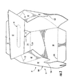
- Fig. 1 is a plan view of the exterior side 1 of a blank, generally indicated at 3, used to form a carton 5 ( Figs. 3-7 ) according to the exemplary embodiment of the disclosure.
- the carton 5 can be used to house a plurality of articles such as containers (not shown).
- the carton 5 is sized to house 20 containers in a 4x5 arrangement, but it is understood that the carton 5 may be sized and shaped to hold containers of a different or same quantity in more than one layer and/or in different row/column arrangements (e.g., 1x6, 3x6, 2x6x2, 3x4x2, 2x9, 2x6, 3x4, etc.).
- the carton 5 includes handles, generally indicated at 11 and 13 for grasping and carrying the carton. As will be discussed below in more detail, handles 11 and 13 are formed from various features in the blank 3.
- the blank 3 has a longitudinal axis L1 and a lateral axis L2.
- the blank 3 comprises a top panel 10 foldably connected to a first side panel 20 at a first lateral fold line 21, a bottom panel 30 foldably connected to the first side panel 20 at a second lateral fold line 31, and a second side panel 40 foldably connected to the bottom panel 30 at a third lateral fold line 41.
- the blank 3 includes an adhesive flap 50 foldably connected to the top panel 10 at a fourth lateral fold line 52.
- the top panel 10 is foldably connected to a first top end flap 12 and a second top end flap 14.
- the first side panel 20 is foldably connected to a first side end flap 22 and a second side end flap 24.
- the bottom panel 30 is foldably connected to a first bottom end flap 32 and a second bottom end flap 34.
- the second side panel 40 is foldably connected to a first side end flap 42 and a second side end flap 44.
- the adhesive flap 50 has a first side adhesive portion 54 and a second side adhesive portion 56.
- the first and second side end flaps 22, 24 each comprise a main panel 26, 28 and an extension panel 64, 65 foldably connected to the main panel 26, 28 along a respective lateral fold line 66, 67.
- the lateral fold lines 66, 67 are generally co-linear with, and extend from the lateral fold line 21.
- the extension panels 64, 65 are foldably connected to the top end flaps 12, 14 along a respective oblique fold line 74, 75.
- the side adhesive portions 54, 56 are foldably connected to a respective extension panel 62, 63 at a respective lateral fold line 68, 69.
- the lateral fold lines 68, 69 are generally co-linear with, and extend from the lateral fold line 52.
- the extension panels 62, 63 are foldably connected to the top end flaps 12, 14 along a respective oblique fold line 72, 73.
- each extension panel 62, 63, 64, 65 is detachably connected to a respective top end flap 12, 14 at a respective breachable line of disruption (e.g., tear line) 100-103.
- the tear lines 100-103 could be cut lines or other lines of weakening without departing from this disclosure.
- the tear lines or cut lines 100-103 extend laterally from the end of a respective oblique fold line 72-75 to a respective edge of one of the top end flaps 12, 14.
- top and bottom end flaps 12 and 32 and side end flaps 22 and 42 close a first end 51 ( Fig. 3 ) of the carton, and the top and bottom end flaps 14 and 34 and side end flaps 24 and 44 close a second end 53 of the carton in a similar manner as the first end.
- different flap arrangements can be used for closing the first end 51 and/or the second end 53 of the carton 5.
- the top and bottom end flaps 12, 32, the side end flaps 22, 42, and the side adhesive flap 54 extend along a first marginal area of the blank 3, and are foldably connected at a first longitudinal fold line 58 that extends along the length of the blank 3.
- the top and bottom end flaps 14, 34, side end flaps 24, 44, and the side adhesive flap 56 extend along a second marginal area of the blank 3, and are foldably connected at a second longitudinal fold line 59 that extends along the length of the blank 3.
- the longitudinal fold lines 58, 59 may be, for example, substantially straight, or offset at one or more locations to account for blank thickness or for other factors.
- the oblique fold lines 74, 75 respectively obliquely extend from an intersection with one of the lateral fold lines 66, 67, one of the longitudinal fold lines 58, 59, and one of the lateral fold lines 21, 52.
- the oblique fold lines 72, 73 respectively obliquely extend from an intersection with one of the lateral fold lines 68, 69, one of the longitudinal fold lines 58, 59, and one of the lateral fold lines 21, 52.
- the oblique fold lines 72-75 could be otherwise shaped, arranged, and/or configured without departing from the disclosure.
- the handle 11 includes an elongate handle flap 131 formed in the top end flap 12 and foldably attached to the top panel at fold line 133.
- the handle flap 131 includes two longitudinal fold lines 135, 137 that extend across the length of the handle panel.
- the fold line 133 extends between respective ends of a tear line 140 that at least partially defines the handle flap 131 in the top panel end flap 12.
- the fold lines 135, 137 respectively extend between the tear line 140 of the elongated handle flap 131.
- the handle flap 131 includes two curved fold lines 141, 143 extending generally laterally between the fold line 137 and a portion of the tear line 141 opposite the fold line.
- the curved fold lines 141, 143 define two end portions 142, 144 of the handle flap 131 and a central portion 146 of the handle panel.
- the two end portion 142, 144 of the handle flap 131 are foldably connected to the central portion 146 to facilitate forming the handle 11 when the handle panel is pushed inward.
- the curved fold lines 141, 143 could be otherwise shaped, arranged, and/or omitted without departing from the disclosure.
- Tear line 140 extends beyond fold line 133 and into elongated panel 132 terminating at fold line 135.
- the features of the handles 11, 13 include respective curved cutouts 162, 164 in the side end flaps 22, 42 to allow the elongate handle panels 131, 133 to fold inwardly when the handle is activated to form handle openings 170 ( Fig. 7 ) in the carton 5.
- the extension panels 62, 64 are discontiguous with the features (e.g., cutout 162, 164) in a respective side end flap 22, 24 that form handle 11.
- the side end flaps 22, 24, 42, 44 could comprise flaps foldably connected to a respective side end flap instead of cutouts 162, 164.
- the flaps 162, 164 are positioned for overlapping a respective handle flap 131 upon activation of a respective handle 11, 13.
- features that form the handle 13 in the bottom end flap 14 are identical to those of handle 11 in the top end flap 12.
- the handle 13 could comprise other features or the handle could be omitted without departing form the disclosure.
- the elongate handle flap 131 is shaped and positioned in the blank 3 so that the handle 11 is activated by pressing on the handle panel and folding the handle panel inward into the curved cutouts 162, 164 to form the handle openings 170 in the carton 5.
- the opening 170 is shaped for insertion of a users fingers during grasping of the carton 5.
- the handle flap 131 is folded inward along fold line 133 to be in opposing face-to-face relation with the interior surface of a respective upper portion of the side panel end flaps 22, 42.
- One or both of the handles 11, 13 may be otherwise shaped and located in the carton 5 without departing from the scope of this disclosure.
- the handle 13 may be similarly activated for grasping of the carton 5.
- the blank 3 can be erected into the carton 5 by folding along the fold lines 21, 31, 41, and 52 and adhering the adhesive flap 50, to the second side panel 40, to form a sleeve 181 ( Fig. 3 ).
- the side adhesive panels 54, 56 can be adhered to respective side end flaps 42, 44, such that the adhesive panels form reinforced portions of the side end flaps.
- the blank 3 may be otherwise configured to have multiple top panels and/or multiple bottom panels without departing from the scope of this disclosure.
- the carton 5 may be a wrap-around type carton, with the blank 3 including locking features that can include primary and secondary locking features as is known in the art. These locking features may also comprise a single locking system or a double locking system such as those disclosed in U.S. Patent Application Serial Nos. 10/183,935 and 10/703,704 .
- the first end 51 of the carton 5 is closed by respectively overlapping and adhering the side end flaps 22, 42 and the top and the bottom end flaps 12, 32.
- the second end of the carton 5 is closed by respectively overlapping and adhering the side end flaps 24, 44 and the top and the bottom end flaps 14, 34.
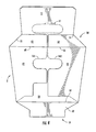
- Figs. 3-6 illustrate the closing of the first end 51 of the carton 5 according to one exemplary method.
- the first side flaps 22, 42 are folded inward causing the top end flap 12 to raise and the extension panels 62, 64 to fold inward at the oblique fold lines 72, 74 to partially close the first end 51 of the carton 5 ( Fig. 4 ).
- the extension panels 62, 64 are in generally face-to-face contact with portions of the top end flap 12 which has been raised by the inward folding of the side and flaps 22, 42.
- the top end flap 12 is then folded downward at fold line 58 forcing the extension panels 62, 64 to be downwardly folded at fold lines 66, 68. In the downwardly folded position of Fig.
- the handle flap 131 is aligned with the curved cutouts 162, 164 ( Fig. 5 ).
- the top end flap 12 contacts the extension panels 62, 64 of the first side panels 22, 42 to fold the extension panels 62, 64 downward along the respective lateral fold lines 66, 68 so that the extension panels 62, 64 overlap a respective upper portion of each of the main panels 26, 46 between the lateral fold lines 66, 68 and the cutouts 162, 164 ( Fig. 5 ).
- the top panel 12 is then further folded downward and secured in the position shown in Fig. 5 so that the handle flap 131 is aligned with the handle cutouts 162, 164.
- the bottom end flap 32 is raised ( Fig. 6 ) to further close the end 51 of the carton 5.
- the exterior surface of the downwardly folded extension panels 62, 64 will typically be in opposing face-to-face contact with a portion of the exterior surface of the side end flaps 22, 42.
- the portion of the exterior surface of the side end flaps 22, 42 that is in face-to-face contact with the exterior surface of the downwardly folded extension panels comprises a respective upper portion of the main panels 26, 46 below the fold lines 66, 68 and above the cutouts 162, 164.
- a portion of the interior surface of the top end flap 12 is in face-to-face contact with the interior surface of the extension panels 62, 64 and a portion of the interior surface of the top end flap is in face-to-face contact with the exterior surface of the main panels 26, 46 of the side end flaps 22.
- the downwardly folded extension panels 62, 64 may be secured to the main panels 26, 46 of the side end flaps 22, 42 by adhesive such as glue.
- the extension panels 62, 64 may be respectively secured to one or both of the top end flap 12 and a respective one of the side end flaps 22, 42.
- the bottom end flap 32 can be secured to one or more of the top end flap 12, and side end flaps 22, 42.
- the side end flaps 24, 44, top end flap 14, and bottom end flap 34 at the second end 53 of the carton 5 can be positioned in a similar manner as described above to close the second end of the carton.
- the end flaps 24, 44, 14, 34 can be alternatively shaped, arranged, and/or positioned without departing from the scope of the disclosure.
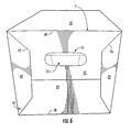
- the handle 11 may be used to grasp the carton 5 by pressing against the elongate handle flap 131 to create the handle opening 170 ( Fig. 7 ) in the closed end 51 of the carton 5.
- the downwardly folded extension panels 62, 64 of the side end flaps 22, 42 provides an extra layer of material above the handle 11 to reinforce the carton 5 when the carton is lifted at the handle.
- the carton 5 has four layers of material (e.g., side end flaps 22, 42, extension panels 62, 64, top end flap 12, and the inwardly folded flap 131) above the handle opening 170 to increase the strength of the carton in the area of the handle.
- the second handle 13 is similar to the handle 11 and is for grasping at the second end (not shown) of the carton in a similar manner as the first handle.
- the handle 11 is shaped and positioned in the carton so that multiple fingers of a user may be placed through the handle opening 170 in the overlapped top end panel 12 and first side panels 22, 42 and the thumb of a user may be placed on the top panel 10 for grasping and lifting the carton 5
- the extension panels 62, 64 increases the strength and rigidity of the carton 5 in the area above the handle 11 to prevent the carton from tearing or otherwise failing when lifted. As illustrated, the extension panels 62, 64, side end flaps 22, 42, and top end flap 12 together form a reinforced region above the handle 11 that has a thickness of three-ply's of material.
- the blank 3 can be, for example, formed from coated paperboard and similar materials.
- the interior and/or exterior sides of the blank 3 can be coated with a clay coating.
- the clay coating may then be printed over with product, advertising, price coding, and other information or images.
- the blank 3 may then be coated with a varnish to protect any information printed on the blank.
- the blank 3 may also be coated with, for example, a moisture barrier layer, on either or both sides of the blank.
- the blank 3 may be constructed of paperboard of a caliper such that it is heavier and more rigid than ordinary paper.
- the blank 3 can also be constructed of other materials, such as cardboard, hard paper, or any other material having properties suitable for enabling the carton 5 to function at least generally as described herein.
- the blank 3 can also be laminated or coated with one or more sheet-like materials at selected panels or panel sections.
- a fold line can be any substantially linear, although not necessarily straight, form of weakening that facilitates folding therealong. More specifically, but not for the purpose of narrowing the scope of the present disclosure, fold lines include: a score line, such as lines formed with a blunt scoring knife, or the like, which creates a crushed portion in the material along the desired line of weakness; a cut that extends partially into a material along the desired line of weakness, and/or a series of cuts that extend partially into and/or completely through the material along the desired line of weakness; and various combinations of these features.
- a score line such as lines formed with a blunt scoring knife, or the like, which creates a crushed portion in the material along the desired line of weakness
- a cut that extends partially into a material along the desired line of weakness, and/or a series of cuts that extend partially into and/or completely through the material along the desired line of weakness; and various combinations of these features.
- a tear line can include: a slit that extends partially into the material along the desired line of weakness, and/or a series of spaced apart slits that extend partially into and/or completely through the material along the desired line of weakness, or various combinations of these features.
- one type tear line is in the form of a series of spaced apart slits that extend completely through the material, with adjacent slits being spaced apart slightly so that a nick (e.g., a small somewhat bridging-like piece of the material) is defined between the adjacent slits for typically temporarily connecting the material across the tear line. The nicks are broken during tearing along the tear line.
- the nicks typically are a relatively small percentage of the tear line, and alternatively the nicks can be omitted from or torn in a tear line such that the tear line is a continuous cut line. That is, it is within the scope of the present disclosure for each of the tear lines to be replaced with a continuous slit, or the like.
- a cut line can be a continuous slit or could be wider than a slit without departing from the present disclosure.
- the above embodiments may be described as having one or more panels adhered together by glue during erection of the carton embodiments.
- glue is intended to encompass all manner of adhesives commonly used to secure carton panels in place.
Description
- The present disclosure generally relates to cartons for holding beverage containers or other types of articles. More specifically, the present disclosure relates to a carton according to the preamble of claim 1, a carton blank according to the preamble of
claim 12 and a method of assembling a carton. - A carton of the generic type and a blank for forming same are known from
US 2006/0278689 A1 . This prior art carton comprises two closed ends each with a handle opening in the respective top end flap. The associated two side end flaps comprise cut-outs which register with the handle opening. Reinforcing panels are foldably connected with the side end flaps to provide for a double layer structure immediately above the handle openings. Said reinforcing panels are confined, in addition to said fold lines, by severance lines which, at least at the erected configuration, separate the reinforcing panels entirely from the adjacent top end flap and partly from the associated side end flap. - A quite similar carton end structure is disclosed in
US 2007/0063003 A1 . - The present invention aims at providing for an improved carton being advantageous notably in terms of erection and closing of its ends.
- According to the present invention, the object set out above is achieved by the carton of claim 1. Moreover, the carton blank of
claim 12 and the carton assembling method of claim 18 solve the above mentioned object. - In general, one aspect of the disclosure is directed to a carton for containing a plurality of articles. The carton comprises a top panel, a bottom panel, a first side panel, a second side panel, a top end flap foldably connected to the top panel, and a side end flap foldably connected to one of the first side panel and the second side panel. The carton includes a handle in the closed end of the carton for grasping and carrying the carton. The side end flap comprises a main panel for closing the closed end of the carton and an extension panel foldably attached to the main panel and the top end flap.
- In another aspect, the disclosure is generally directed to a carton for containing a plurality of articles. The carton comprises a plurality of panels that extends at least partially around an interior of the carton. The plurality of panels comprise a top panel, a bottom panel, a first side panel, and a second side panel. At least two end flaps are respectively foldably attached to respective panels of the plurality of panels. The end flaps are overlapped with respect to one another and thereby at least partially form a closed end of the carton. The at least two end flaps comprise at least one side end flap and at least one top end flap. A handle is in the closed end of the carton for grasping and carrying the carton. The at least one side end flap of the at least two end flaps comprises a main panel for closing the closed end of the carton and an extension panel foldably connected to the main panel and the at least one top end flap. The extension panel is positioned above the handle to reinforce the carton when the at least one top end flap is closed.
- In another aspect, the disclosure is generally directed to a blank for forming a carton. The blank comprises a plurality of panels comprising a top panel, a bottom panel, a first side panel, and a second side panel. At least two end flaps respectively foldably attached to respective panels of the plurality of panels at a first marginal end of the blank. The at least two end flaps comprises at least one side end flap and at least one top end flap. The blank has features in the at least two end flaps that are for cooperating to at least partially define a handle in a carton erected from the blank. The at least one side end flap of the at least two end flaps comprises a main panel for closing an end of the carton erected from the blank and an extension panel foldably attached to the main panel and the at least one top end flap. The extension panel is for being positioned above the handle when the blank is erected into the carton.
- In another aspect, the disclosure is generally directed to a method of assembling a carton. The method comprises obtaining a carton comprising a plurality of panels, comprising a top panel, a bottom panel, a first side panel, and a second side panel. The carton comprises at least one side end flap foldably attached to at least one of the first and second side panels at a first end of the carton, and at least one top end flap foldably attached to the top panel at the first end. The at least one side end flap comprises a main panel for at least partially forming a closed end of the carton and an extension panel foldably attached to the main panel and the top end flap. The method further comprises folding the at least one side end flap to at least partially close the first end of the carton, folding the top end flap downward to contact the extension panel and fold the extension panel downward to overlap the main panel, and securing the top panel to at least partially close the carton.
- Those skilled in the art will appreciate the above stated advantages and other advantages and benefits of various additional embodiments reading the following detailed description of the embodiments with reference to the below-listed drawing figures.
- According to common practice, the various features of the drawings discussed below are not necessarily drawn to scale. Dimensions of various features and elements in the drawings may be expanded or reduced to more clearly illustrate the embodiments of the disclosure.
-
Figs. 1-7 are respective views of a blank and/or a carton according to one embodiment of the disclosure. - Corresponding parts are designated by corresponding reference numbers throughout the drawings.
- The present disclosure generally relates to cartons that contain articles such as containers, bottles, cans, etc. The articles can be used for packaging food and beverage products, for example. The articles can be made from materials suitable in composition for packaging the particular food or beverage item, and the materials include, but are not limited to, aluminum and/or other metals; glass; plastics such as PET, LDPE, LLDPE, HDPE, PP, PS, PVC, EVOH, and Nylon; and the like, or any combination thereof.
- Cartons according to the present disclosure can accommodate articles of any shape. For the purpose of illustration and not for the purpose of limiting the scope of the disclosure, the following detailed description describes beverage containers (e.g., glass or plastic beverage bottles) as disposed within the carton embodiments. In this specification, the terms "lower," "bottom," "upper" and "top" indicate orientations determined in relation to fully erected and upright cartons.
-
Fig. 1 is a plan view of the exterior side 1 of a blank, generally indicated at 3, used to form a carton 5 (Figs. 3-7 ) according to the exemplary embodiment of the disclosure. Thecarton 5 can be used to house a plurality of articles such as containers (not shown). In the illustrated embodiment, thecarton 5 is sized to house 20 containers in a 4x5 arrangement, but it is understood that thecarton 5 may be sized and shaped to hold containers of a different or same quantity in more than one layer and/or in different row/column arrangements (e.g., 1x6, 3x6, 2x6x2, 3x4x2, 2x9, 2x6, 3x4, etc.). In the illustrated embodiment, thecarton 5 includes handles, generally indicated at 11 and 13 for grasping and carrying the carton. As will be discussed below in more detail,handles - The blank 3 has a longitudinal axis L1 and a lateral axis L2. In the illustrated embodiment, the blank 3 comprises a
top panel 10 foldably connected to a first side panel 20 at a firstlateral fold line 21, abottom panel 30 foldably connected to the first side panel 20 at a secondlateral fold line 31, and asecond side panel 40 foldably connected to thebottom panel 30 at a thirdlateral fold line 41. In the illustrated embodiment, the blank 3 includes anadhesive flap 50 foldably connected to thetop panel 10 at a fourthlateral fold line 52. - The
top panel 10 is foldably connected to a firsttop end flap 12 and a secondtop end flap 14. The first side panel 20 is foldably connected to a firstside end flap 22 and a secondside end flap 24. Thebottom panel 30 is foldably connected to a firstbottom end flap 32 and a secondbottom end flap 34. Thesecond side panel 40 is foldably connected to a firstside end flap 42 and a secondside end flap 44. Theadhesive flap 50 has a first sideadhesive portion 54 and a second sideadhesive portion 56. In the illustrated embodiment, the first and secondside end flaps main panel extension panel main panel lateral fold line lateral fold lines lateral fold line 21. Theextension panels oblique fold line - As further illustrated, the side
adhesive portions respective extension panel lateral fold line lateral fold lines lateral fold line 52. Theextension panels oblique fold line - In the illustrated embodiment, each
extension panel top end flap - When the
carton 5 is erected, the top and bottom end flaps 12 and 32 and side end flaps 22 and 42 close a first end 51 (Fig. 3 ) of the carton, and the top and bottom end flaps 14 and 34 and side end flaps 24 and 44 close asecond end 53 of the carton in a similar manner as the first end. In accordance with an alternative embodiment of the present disclosure, different flap arrangements can be used for closing thefirst end 51 and/or thesecond end 53 of thecarton 5. - The top and bottom end flaps 12, 32, the side end flaps 22, 42, and the side
adhesive flap 54 extend along a first marginal area of the blank 3, and are foldably connected at a firstlongitudinal fold line 58 that extends along the length of the blank 3. The top and bottom end flaps 14, 34, side end flaps 24, 44, and the sideadhesive flap 56 extend along a second marginal area of the blank 3, and are foldably connected at a secondlongitudinal fold line 59 that extends along the length of the blank 3. Thelongitudinal fold lines - In one embodiment, the
oblique fold lines lateral fold lines longitudinal fold lines lateral fold lines oblique fold lines lateral fold lines longitudinal fold lines lateral fold lines - In the illustrated embodiment, the features that form the two
handles handles 11 is described in detail herein. As shown inFig. 2 , thehandle 11 includes anelongate handle flap 131 formed in thetop end flap 12 and foldably attached to the top panel atfold line 133. In the illustrated embodiment, thehandle flap 131 includes twolongitudinal fold lines fold line 133 extends between respective ends of atear line 140 that at least partially defines thehandle flap 131 in the toppanel end flap 12. The fold lines 135, 137 respectively extend between thetear line 140 of theelongated handle flap 131. As shown inFig. 2 , thefold lines strips handle flap 131 includes twocurved fold lines fold line 137 and a portion of thetear line 141 opposite the fold line. Thecurved fold lines end portions 142, 144 of thehandle flap 131 and a central portion 146 of the handle panel. The twoend portion 142, 144 of thehandle flap 131 are foldably connected to the central portion 146 to facilitate forming thehandle 11 when the handle panel is pushed inward. Thecurved fold lines Tear line 140 extends beyondfold line 133 and intoelongated panel 132 terminating atfold line 135. - As shown in
Figs. 3 and4 , the features of thehandles curved cutouts elongate handle panels Fig. 7 ) in thecarton 5. In the illustrated embodiment, theextension panels cutout 162, 164) in a respectiveside end flap handle 11. As shown inFig. 1 , the side end flaps 22, 24, 42, 44 could comprise flaps foldably connected to a respective side end flap instead ofcutouts flaps respective handle flap 131 upon activation of arespective handle handle 13 in thebottom end flap 14 are identical to those ofhandle 11 in thetop end flap 12. Thehandle 13 could comprise other features or the handle could be omitted without departing form the disclosure. - The
elongate handle flap 131 is shaped and positioned in the blank 3 so that thehandle 11 is activated by pressing on the handle panel and folding the handle panel inward into thecurved cutouts handle openings 170 in thecarton 5. Theopening 170 is shaped for insertion of a users fingers during grasping of thecarton 5. In the illustrated embodiment, when thecarton 5 is closed and thehandle 11 activated for grasping of the carton (Fig. 7 ), thehandle flap 131 is folded inward alongfold line 133 to be in opposing face-to-face relation with the interior surface of a respective upper portion of the side panel end flaps 22, 42. One or both of thehandles carton 5 without departing from the scope of this disclosure. Thehandle 13 may be similarly activated for grasping of thecarton 5. - In accordance with the exemplary embodiment, the blank 3 can be erected into the
carton 5 by folding along the fold lines 21, 31, 41, and 52 and adhering theadhesive flap 50, to thesecond side panel 40, to form a sleeve 181 (Fig. 3 ). The sideadhesive panels carton 5 may be a wrap-around type carton, with the blank 3 including locking features that can include primary and secondary locking features as is known in the art. These locking features may also comprise a single locking system or a double locking system such as those disclosed inU.S. Patent Application Serial Nos. 10/183,935 and10/703,704 - In the illustrated embodiment, the
first end 51 of thecarton 5 is closed by respectively overlapping and adhering the side end flaps 22, 42 and the top and the bottom end flaps 12, 32. The second end of thecarton 5 is closed by respectively overlapping and adhering the side end flaps 24, 44 and the top and the bottom end flaps 14, 34. Once the blank 3 is formed into thesleeve 181 and with the second end closed, the containers may be loaded in thecarton 5 from thefirst end 51 and then the first end may be closed by overlapping and gluing the side end flaps 22, 42. Alternative loading and closing steps may be used without departing from the scope of this disclosure. -
Figs. 3-6 illustrate the closing of thefirst end 51 of thecarton 5 according to one exemplary method. From the partially assembled position ofFig. 3 , the first side flaps 22, 42 are folded inward causing thetop end flap 12 to raise and theextension panels oblique fold lines first end 51 of the carton 5 (Fig. 4 ). Theextension panels top end flap 12 which has been raised by the inward folding of the side and flaps 22, 42. Thetop end flap 12 is then folded downward atfold line 58 forcing theextension panels fold lines Fig. 5 , thehandle flap 131 is aligned with thecurved cutouts 162, 164 (Fig. 5 ). When lowered from the position ofFig. 4 , thetop end flap 12 contacts theextension panels first side panels extension panels lateral fold lines extension panels main panels 26, 46 between thelateral fold lines cutouts 162, 164 (Fig. 5 ). Thetop panel 12 is then further folded downward and secured in the position shown inFig. 5 so that thehandle flap 131 is aligned with thehandle cutouts top end flap 12 lowered, thebottom end flap 32 is raised (Fig. 6 ) to further close theend 51 of thecarton 5. In one embodiment, the exterior surface of the downwardly foldedextension panels main panels 26, 46 below the fold lines 66, 68 and above thecutouts closed end 51 of the carton a portion of the interior surface of thetop end flap 12 is in face-to-face contact with the interior surface of theextension panels main panels 26, 46 of the side end flaps 22. The downwardly foldedextension panels main panels 26, 46 of the side end flaps 22, 42 by adhesive such as glue. Also, theextension panels top end flap 12 and a respective one of the side end flaps 22, 42. Further, thebottom end flap 32 can be secured to one or more of thetop end flap 12, and side end flaps 22, 42. - The side end flaps 24, 44,
top end flap 14, andbottom end flap 34 at thesecond end 53 of thecarton 5 can be positioned in a similar manner as described above to close the second end of the carton. Alternatively, the end flaps 24, 44, 14, 34 can be alternatively shaped, arranged, and/or positioned without departing from the scope of the disclosure. - The
handle 11 may be used to grasp thecarton 5 by pressing against theelongate handle flap 131 to create the handle opening 170 (Fig. 7 ) in theclosed end 51 of thecarton 5. The downwardly foldedextension panels handle 11 to reinforce thecarton 5 when the carton is lifted at the handle. In the area above thehandle 11, thecarton 5 has four layers of material (e.g., side end flaps 22, 42,extension panels top end flap 12, and the inwardly folded flap 131) above thehandle opening 170 to increase the strength of the carton in the area of the handle. Thesecond handle 13 is similar to thehandle 11 and is for grasping at the second end (not shown) of the carton in a similar manner as the first handle. Thehandle 11 is shaped and positioned in the carton so that multiple fingers of a user may be placed through thehandle opening 170 in the overlappedtop end panel 12 andfirst side panels top panel 10 for grasping and lifting thecarton 5 Theextension panels carton 5 in the area above thehandle 11 to prevent the carton from tearing or otherwise failing when lifted. As illustrated, theextension panels top end flap 12 together form a reinforced region above thehandle 11 that has a thickness of three-ply's of material. - The blank 3 according to the present disclosure can be, for example, formed from coated paperboard and similar materials. For example, the interior and/or exterior sides of the blank 3 can be coated with a clay coating. The clay coating may then be printed over with product, advertising, price coding, and other information or images. The blank 3 may then be coated with a varnish to protect any information printed on the blank. The blank 3 may also be coated with, for example, a moisture barrier layer, on either or both sides of the blank. In accordance with the above-described embodiments, the blank 3 may be constructed of paperboard of a caliper such that it is heavier and more rigid than ordinary paper. The blank 3 can also be constructed of other materials, such as cardboard, hard paper, or any other material having properties suitable for enabling the
carton 5 to function at least generally as described herein. The blank 3 can also be laminated or coated with one or more sheet-like materials at selected panels or panel sections. - In accordance with the above-described embodiments of the present disclosure, a fold line can be any substantially linear, although not necessarily straight, form of weakening that facilitates folding therealong. More specifically, but not for the purpose of narrowing the scope of the present disclosure, fold lines include: a score line, such as lines formed with a blunt scoring knife, or the like, which creates a crushed portion in the material along the desired line of weakness; a cut that extends partially into a material along the desired line of weakness, and/or a series of cuts that extend partially into and/or completely through the material along the desired line of weakness; and various combinations of these features.
- As an example, a tear line can include: a slit that extends partially into the material along the desired line of weakness, and/or a series of spaced apart slits that extend partially into and/or completely through the material along the desired line of weakness, or various combinations of these features. As a more specific example, one type tear line is in the form of a series of spaced apart slits that extend completely through the material, with adjacent slits being spaced apart slightly so that a nick (e.g., a small somewhat bridging-like piece of the material) is defined between the adjacent slits for typically temporarily connecting the material across the tear line. The nicks are broken during tearing along the tear line. The nicks typically are a relatively small percentage of the tear line, and alternatively the nicks can be omitted from or torn in a tear line such that the tear line is a continuous cut line. That is, it is within the scope of the present disclosure for each of the tear lines to be replaced with a continuous slit, or the like. For example, a cut line can be a continuous slit or could be wider than a slit without departing from the present disclosure.
- The above embodiments may be described as having one or more panels adhered together by glue during erection of the carton embodiments. The term "glue" is intended to encompass all manner of adhesives commonly used to secure carton panels in place.
- The foregoing description of the disclosure illustrates and describes various embodiments. As various changes could be made in the above construction without departing from the scope of the disclosure, it is intended that all matter contained in the above description or shown in the accompanying drawings shall be interpreted as illustrative and not in a limiting sense. Furthermore, the scope of the present disclosure covers various modifications, combinations, alterations, etc., of the above-described embodiments. Additionally, the disclosure shows and describes only selected embodiments of the disclosure, but the disclosure is capable of use in various other combinations, modifications, and environments and is capable of changes or modifications within the scope of the inventive concept as expressed herein, commensurate with the above teachings, and/or within the skill or knowledge of the relevant art. Furthermore, certain features and characteristics of each embodiment may be selectively interchanged and applied to other illustrated and non-illustrated embodiments of the disclosure.
Claims (22)
- A carton (5) for containing a plurality of articles, the carton comprising:a plurality of panels that extends at least partially around an interior of the carton, the plurality of panels comprise a top panel (10), a bottom panel (30), a first side panel (20), and a second side panel (40);at least two end flaps (12, 14, 22, 24, 32, 34, 42, 44) respectively foldably attached to respective panels of the plurality of panels, wherein the end flaps are overlapped with respect to one another and thereby at least partially form a closed end (51, 53) of the carton, the at least two end flaps comprising at least one side end flap (22, 24, 42, 44) and at least one top end flap (12, 14); anda handle (11, 13) in the closed end of the carton for grasping and carrying the carton,the at least one side end flap (22, 24) of the at least two end flaps comprises a main panel (26, 28) for closing the closed end of the carton and an extension panel (62, 63, 64, 65) foldably connected to the main panel and the extension panel being positioned above the handle (11, 13) to reinforce the carton when the at least one top end flap (12, 14) is closed,characterized in thatsaid extension panel (62, 63, 64, 65) is foldably connected to the at least one top end flap (12, 14).
- The carton (5) of claim 1, wherein the extension panel (62, 63, 64, 65) is disposed between the main panel (26, 28) and the top end flap (12, 14), the top end flap at least partially overlaps the main panel.
- The carton (5) of claim 2 wherein the extension panel (62, 63, 64, 65) is in face-to-face contact with an exterior surface of the main panel (26, 28).
- The carton (5) of claim 2 wherein the extension panel (62, 63, 64, 65) is in face-to-face contact with an interior surface of the top end flap (12, 14).
- The carton (5) of claim 1 wherein the at least one side end flap comprises a first side end flap (22, 24) foldably connected to the first side panel (20) and a second side end flap (42, 44) foldably connected to the second side panel (40).
- The carton (5) of claim 5 wherein the handle (11, 13) comprises a handle cutout (162, 164) in each of the first side end flap (22, 24) and the second side end flap (42, 44).
- The carton (5) of claim 6 wherein the handle (11, 13) comprises a handle flap (131) foldably attached to the top end flap (12, 14) for forming a handle opening (170) aligned with the handle cutouts (162, 164).
- The carton (5) of claim 1 wherein the extension panel (62, 63, 64, 65) is downwardly folded when the top end flap (12, 14) is closed.
- The carton (5) of claim 1 wherein the extension panel (62, 63, 64, 65) is foldably connected to the main panel (26, 28) at a first fold line (66, 67, 68, 69) and the extension panel is foldably connected to the at least one top end flap (12, 14) at a second fold line (72, 73, 74, 75) that is oblique relative to the first fold line.
- The carton (5) of claim 1 wherein:the closed end (51, 53) is a first closed end (51);the end flaps (12, 14, 22, 24, 32, 34, 42, 44) are first end flaps (12, 22, 32, 42) that are overlapped with respect to one another to form the first closed end; andthe carton further includes at least two second end flaps (14, 24, 34, 44) respectively foldably attached to respective panels of the plurality of panels (10, 20, 30, 40), wherein the second end flaps are overlapped with respect to one another to form a second closed end (53) of the carton at an opposite end from the first closed end (51).
- The carton (5) of claim 1 in combination with a plurality of articles, the plurality of articles comprising bottles that are arranged in an upright position in the carton.
- A blank (3) for forming a carton (5) comprising:a plurality of panels comprising a top panel (10), a bottom panel (30), a first side panel (20), and a second side panel (40);at least two end flaps (12, 14, 22, 24, 32, 34, 42, 44) respectively foldably attached to respective panels of the plurality of panels at a first marginal end of the blank, the at least two end flaps comprising at least one side end flap (22, 24, 42, 44) and at least one top end flap (12, 14); andfeatures in the at least two end flaps, wherein the features are for cooperating to at least partially define a handle (11, 13) in a carton erected from the blank,the at least one side end flap (22, 24, 42, 44) of the at least two end flaps comprises a main panel (26, 28) for closing an end of the carton erected from the blank and an extension panel (62, 63, 64, 65) foldably connected to the main panel at a first fold line (66, 67, 68, 69), the extension panel (62, 63, 64, 65) is for being positioned above the handle (11, 13) when the blank is erected into the carton,characterized in thatthe extension panel (62, 63, 64, 65) is foldably connected to the at least one top end flap (12, 14) at a second fold line (72, 73, 74, 75) that is oblique relative to the first fold line (66, 67, 68, 69).
- The blank (3) of claim 12 wherein the at least one side end flap (22, 24, 42, 44) comprises a first side end flap (22, 24) foldably attached to the first side panel (20) and a second side end flap (42, 44) foldably attached to the second side panel (40).
- The blank (3) of claim 13 wherein the handle (11, 13) comprises a handle cutout (162, 164) in each of the first side end flap (22, 24) and the second side end flap (42, 44).
- The blank (3) of claim 14 wherein the handle (11, 13) comprises a handle flap (131) foldably attached to the top end flap (12, 14) for forming a handle opening (170) aligned with the handle cutouts (162, 164).
- The blank (3) of claim 15 wherein each extension panel (62, 63, 64, 65) is for being downwardly folded by engagement with the top end flap (12, 14) when the carton (5) erected from the blank is closed.
- The blank (3) of claim 12 wherein:the end flaps (12, 14, 22, 24, 32, 34, 42, 44) are first end flaps (12, 22, 32, 42) that are overlapped with respect to one another to form a first closed end (51) of the carton (5) erected from the blank; andthe blank further includes at least two second end flaps (14, 24, 34, 44) respectively foldably attached to respective panels (10, 20, 30, 40) of the plurality of panels at a second marginal end of the blank, the at least two second end flaps are overlapped with respect to one another to form a second closed end (53) of the carton (5) erected from the blank.
- A method of assembling a carton (5) comprising:obtaining a carton comprising a plurality of panels, comprising a top panel (10), a bottom panel (30), a first side panel (20), and a second side panel (40), at least one side end flap (22, 24, 42, 44) foldably attached to at least one of the first and second side panels (20, 40) at a first end (51,53) of the carton, at least one top end flap (12, 14) foldably attached to the top panel (10) at the first end, the at least one side end flap (22, 24, 42, 44) comprising a main panel (26, 28) for at least partially forming a closed end of the carton and an extension panel (62, 63, 64, 65) foldably connected to the main panel at a first fold line (66, 67, 68, 69) and to the top end flap (12, 14) at a second fold line (72, 73, 74, 75) that is oblique to the first fold line (66, 67, 68, 69);folding the at least one side end flap (22, 24, 42, 44) to at least partially close the first end of the carton;folding the top end flap (12, 14) downward to contact the extension panel (62, 63, 64, 65) and fold the extension panel downward to overlap the main panel (26, 28); andsecuring the top end flap (12, 14) to at least partially close the carton.
- The method of claim 18 further comprising securing the extension panel (62, 63, 64, 65) to the main panel (26, 28).
- The method of claim 18 wherein the at least one side end flap (22, 24, 42, 44) comprises two side end flaps (22, 42).
- The method of claim 20 wherein the handle (11, 13) comprises a handle flap (131) foldably attached to the top end flap (12, 14) and handle cutouts (162, 164) in the two side end flaps (22, 42), and the method further comprises folding the handle flap (131) into the handle cutouts (162, 164) in the at least two side end flaps (22, 42) to form a handle opening (170) of the carton (5).
- The method of claim 18 wherein the carton (5) further comprises a plurality of end flaps (14, 24, 34, 44) at the second end (53) of the carton (5) and the method further comprises overlapping the plurality of end flaps at the second end to close the second end of the carton.
Applications Claiming Priority (2)
| Application Number | Priority Date | Filing Date | Title |
|---|---|---|---|
| US19230208P | 2008-09-17 | 2008-09-17 | |
| PCT/US2009/057247 WO2010033657A1 (en) | 2008-09-17 | 2009-09-17 | Carton with reinforced handle |
Publications (3)
| Publication Number | Publication Date |
|---|---|
| EP2326568A1 EP2326568A1 (en) | 2011-06-01 |
| EP2326568A4 EP2326568A4 (en) | 2012-08-29 |
| EP2326568B1 true EP2326568B1 (en) | 2014-01-08 |
Family
ID=42039855
Family Applications (1)
| Application Number | Title | Priority Date | Filing Date |
|---|---|---|---|
| EP09815163.2A Active EP2326568B1 (en) | 2008-09-17 | 2009-09-17 | Carton with reinforced handle |
Country Status (5)
| Country | Link |
|---|---|
| US (1) | US7984843B2 (en) |
| EP (1) | EP2326568B1 (en) |
| CA (1) | CA2737409C (en) |
| ES (1) | ES2443534T3 (en) |
| WO (1) | WO2010033657A1 (en) |
Families Citing this family (21)
| Publication number | Priority date | Publication date | Assignee | Title |
|---|---|---|---|---|
| GB0423162D0 (en) | 2004-10-19 | 2004-11-24 | Graphic Packaging Int Inc | Fully enclosed carton |
| US7998047B2 (en) * | 2005-09-21 | 2011-08-16 | Graphic Packaging International, Inc. | Carton with reinforced handle |
| ATE471879T1 (en) * | 2005-11-08 | 2010-07-15 | Graphic Packaging Int Inc | CARTON WITH REINFORCED HANDLE |
| ES2443534T3 (en) | 2008-09-17 | 2014-02-19 | Graphic Packaging International, Inc. | Cardboard box with reinforced handle |
| US8950657B2 (en) | 2010-11-01 | 2015-02-10 | Graphic Packaging International, Inc. | Carton with handle |
| WO2012094557A2 (en) | 2011-01-07 | 2012-07-12 | Graphic Packaging International, Inc. | Carton with handle |
| CN103889852B (en) * | 2011-10-17 | 2016-08-31 | 印刷包装国际公司 | Carton, carton blank and the method forming carton |
| MX343676B (en) | 2012-02-16 | 2016-11-16 | Graphic Packaging Int Inc | Carton with reinforced handle. |
| US9073680B2 (en) | 2012-05-03 | 2015-07-07 | Graphic Packaging International, Inc. | Carton with article protection features |
| AU2013290754B2 (en) | 2012-07-17 | 2017-02-09 | Graphic Packaging International, Llc | Carton with insert |
| AU2015305741B2 (en) | 2014-08-19 | 2019-01-31 | Graphic Packaging International, Llc | Carton with reinforced handle |
| WO2016069534A1 (en) | 2014-10-27 | 2016-05-06 | Graphic Packaging International, Inc. | Carton for articles |
| US10549875B2 (en) | 2014-10-30 | 2020-02-04 | Graphic Packaging International, Llc | Carton with handle |
| ES2754650T3 (en) | 2014-11-17 | 2020-04-20 | Graphic Packaging Int Llc | Cardboard box with reinforcing elements |
| WO2016081299A1 (en) | 2014-11-17 | 2016-05-26 | Graphic Packaging International, Inc. | Carton with reinforcement features |
| ES2736105T3 (en) | 2015-02-20 | 2019-12-26 | Intercontinental Great Brands Llc | Recerrable container with carrying handle |
| USD764288S1 (en) | 2015-02-20 | 2016-08-23 | Intercontinental Great Brands Llc | Carton with handle |
| KR20200003375A (en) | 2017-04-19 | 2020-01-09 | 웨스트락 패키징 시스템스, 엘엘씨 | Blank for carton and carton |
| AU2018269586A1 (en) | 2017-05-18 | 2019-11-14 | Westrock Packaging Systems, Llc | Carton and blank therefor |
| USD1006618S1 (en) | 2020-07-31 | 2023-12-05 | Pratt Corrugated Holdings, Inc. | Double-handle box |
| US11760531B2 (en) | 2020-10-09 | 2023-09-19 | Pratt Corrugated Holdings, Inc | Double-handle box |
Family Cites Families (35)
| Publication number | Priority date | Publication date | Assignee | Title |
|---|---|---|---|---|
| US2196502A (en) | 1939-02-15 | 1940-04-09 | Container Corp | Container |
| US2308050A (en) | 1940-04-12 | 1943-01-12 | Waldorf Paper Prod Co | Box |
| US2386905A (en) | 1942-12-26 | 1945-10-16 | Curt J Meltzen | Carton and carton blank |
| US2648484A (en) | 1951-02-19 | 1953-08-11 | Belsinger Inc | Heavy duty fiber container |
| US2900123A (en) | 1957-06-12 | 1959-08-18 | Container Corp | Heavy duty paperboard container |
| US3173596A (en) | 1963-11-18 | 1965-03-16 | Owens Illinois Glass Co | Paperboard container |
| US3756499A (en) | 1972-03-09 | 1973-09-04 | Union Camp Corp | Box with five panel ends |
| US4005815A (en) | 1976-02-19 | 1977-02-01 | The Interstate Folding Box Company | Carton with self-contained reinforced handle |
| US4538759A (en) | 1983-09-01 | 1985-09-03 | Champion International Corporation | Can carton with three ply handle structure |
| US4621766A (en) | 1985-06-28 | 1986-11-11 | Inland Container Corporation | Triple-end container and blank therefor |
| US5072876A (en) * | 1990-10-30 | 1991-12-17 | Riverwood International Corporation | Article carrier with side handles |
| US5119985A (en) | 1991-10-16 | 1992-06-09 | Riverwood Natural Resources Corporation | Reinforced carton handle |
| US5350109A (en) | 1993-03-08 | 1994-09-27 | Labatt Brewing Company Limited | Paperboard carton handholds |
| US5588585A (en) | 1996-03-15 | 1996-12-31 | Inland Container Corporation | Automatic set-up carton with corner posts |
| US5702876A (en) * | 1996-04-30 | 1997-12-30 | Minnesota Mining And Manufacturing Company | Photographic film base and color photographic material comprising a binderless magnetic layer |
| GB9707006D0 (en) | 1997-04-07 | 1997-05-28 | Smith David S Packaging | Carton and blank therefor |
| GB9725242D0 (en) | 1997-11-28 | 1998-01-28 | Riverwood Int Corp | Paperboard carton with end wall handles |
| DE29815677U1 (en) | 1998-09-01 | 1998-11-19 | Fcp Europa Carton Faltschachte | Container carrier |
| US6112977A (en) | 1999-02-03 | 2000-09-05 | Riverwood International Corporation | Bottle carrier with dividers |
| CA2399035C (en) | 2000-03-07 | 2009-04-28 | Riverwood International Corporation | Handle arrangement for a carton |
| GB0017723D0 (en) | 2000-07-20 | 2000-09-06 | Riverwood Int Corp | Carton having a handle |
| US6402020B1 (en) | 2001-01-08 | 2002-06-11 | Weyerhaeuser Company | Container with locking reinforcement panels |
| US6958992B2 (en) * | 2001-03-16 | 2005-10-25 | Mitel Corporation | Registering an IP phone with an IP phone switch |
| US6631803B2 (en) * | 2001-03-21 | 2003-10-14 | Coors Brewing Company | Beverage cooler box |
| US6968992B2 (en) | 2003-10-24 | 2005-11-29 | Graphic Packaging International, Inc. | Handle and top handle reinforcement for a paperboard carton |
| US20050189405A1 (en) | 2004-02-27 | 2005-09-01 | Jean-Manuel Gomes | Three by four can package dispensing carton |
| GB0423162D0 (en) | 2004-10-19 | 2004-11-24 | Graphic Packaging Int Inc | Fully enclosed carton |
| US7743970B2 (en) | 2005-06-13 | 2010-06-29 | Meadwestvaco Packaging Systems, Llc | Carton with reinforced end handles |
| US7998047B2 (en) | 2005-09-21 | 2011-08-16 | Graphic Packaging International, Inc. | Carton with reinforced handle |
| ATE471879T1 (en) * | 2005-11-08 | 2010-07-15 | Graphic Packaging Int Inc | CARTON WITH REINFORCED HANDLE |
| AU2007208324B2 (en) | 2006-01-25 | 2010-08-26 | Graphic Packaging International, Inc. | Side handles for a carton |
| WO2007100890A1 (en) | 2006-03-01 | 2007-09-07 | Graphic Packaging International, Inc. | Carton with multi-ply handle |
| US7780067B2 (en) | 2006-08-31 | 2010-08-24 | Meadwestvaco Packaging Systems, Llc | Carton with reinforced handle openings |
| AU2007319265B2 (en) | 2006-11-15 | 2014-02-13 | Meadwestvaco Packaging Systems, Llc | Carton with multiple ply end handle reinforcement |
| ES2443534T3 (en) | 2008-09-17 | 2014-02-19 | Graphic Packaging International, Inc. | Cardboard box with reinforced handle |
-
2009
- 2009-09-17 ES ES09815163.2T patent/ES2443534T3/en active Active
- 2009-09-17 WO PCT/US2009/057247 patent/WO2010033657A1/en active Application Filing
- 2009-09-17 US US12/561,379 patent/US7984843B2/en active Active
- 2009-09-17 EP EP09815163.2A patent/EP2326568B1/en active Active
- 2009-09-17 CA CA2737409A patent/CA2737409C/en active Active
Also Published As
| Publication number | Publication date |
|---|---|
| CA2737409C (en) | 2012-11-20 |
| ES2443534T3 (en) | 2014-02-19 |
| EP2326568A4 (en) | 2012-08-29 |
| US20100025457A1 (en) | 2010-02-04 |
| US7984843B2 (en) | 2011-07-26 |
| EP2326568A1 (en) | 2011-06-01 |
| WO2010033657A1 (en) | 2010-03-25 |
| CA2737409A1 (en) | 2010-03-25 |
Similar Documents
| Publication | Publication Date | Title |
|---|---|---|
| EP2326568B1 (en) | Carton with reinforced handle | |
| EP1963191B1 (en) | Carton with reinforced handle | |
| CA2623435C (en) | Carton with reinforced handle | |
| EP2616356B1 (en) | Carton with insert | |
| EP2593380B1 (en) | Carton with handle | |
| EP2841353B1 (en) | Carton with insert | |
| EP2470439B1 (en) | Carton with insert | |
| EP2379421B1 (en) | Carton with reinforcing insert | |
| EP2874905B1 (en) | Carton with insert | |
| EP2627575B1 (en) | Carton with reinforced top panel | |
| EP2768745B1 (en) | Carton with handle | |
| WO2010022025A1 (en) | Carton with insert | |
| EP2454168A2 (en) | Carton with insert | |
| EP3212532B1 (en) | Carton with handle | |
| EP2588385B1 (en) | Carton with insert | |
| CA2868840A1 (en) | Carton with handle |
Legal Events
| Date | Code | Title | Description |
|---|---|---|---|
| PUAI | Public reference made under article 153(3) epc to a published international application that has entered the european phase |
Free format text: ORIGINAL CODE: 0009012 |
|
| 17P | Request for examination filed |
Effective date: 20110317 |
|
| AK | Designated contracting states |
Kind code of ref document: A1 Designated state(s): AT BE BG CH CY CZ DE DK EE ES FI FR GB GR HR HU IE IS IT LI LT LU LV MC MK MT NL NO PL PT RO SE SI SK SM TR |
|
| AX | Request for extension of the european patent |
Extension state: AL BA RS |
|
| RIN1 | Information on inventor provided before grant (corrected) |
Inventor name: DE PAULA, ANDREA, COLTRI Inventor name: COOPER, LEONARD, M. |
|
| DAX | Request for extension of the european patent (deleted) | ||
| A4 | Supplementary search report drawn up and despatched |
Effective date: 20120801 |
|
| RIC1 | Information provided on ipc code assigned before grant |
Ipc: B65D 71/12 20060101ALI20120726BHEP Ipc: B65D 71/32 20060101AFI20120726BHEP Ipc: B65D 5/02 20060101ALI20120726BHEP Ipc: B65D 5/462 20060101ALI20120726BHEP Ipc: B65D 71/36 20060101ALI20120726BHEP |
|
| GRAP | Despatch of communication of intention to grant a patent |
Free format text: ORIGINAL CODE: EPIDOSNIGR1 |
|
| INTG | Intention to grant announced |
Effective date: 20130802 |
|
| RIN1 | Information on inventor provided before grant (corrected) |
Inventor name: COOPER, LEONARD, M. Inventor name: DE PAULA, ANDREA, COLTRI |
|
| GRAS | Grant fee paid |
Free format text: ORIGINAL CODE: EPIDOSNIGR3 |
|
| GRAA | (expected) grant |
Free format text: ORIGINAL CODE: 0009210 |
|
| AK | Designated contracting states |
Kind code of ref document: B1 Designated state(s): AT BE BG CH CY CZ DE DK EE ES FI FR GB GR HR HU IE IS IT LI LT LU LV MC MK MT NL NO PL PT RO SE SI SK SM TR |
|
| REG | Reference to a national code |
Ref country code: GB Ref legal event code: FG4D |
|
| REG | Reference to a national code |
Ref country code: CH Ref legal event code: EP |
|
| REG | Reference to a national code |
Ref country code: IE Ref legal event code: FG4D |
|
| REG | Reference to a national code |
Ref country code: AT Ref legal event code: REF Ref document number: 648582 Country of ref document: AT Kind code of ref document: T Effective date: 20140215 |
|
| REG | Reference to a national code |
Ref country code: ES Ref legal event code: FG2A Ref document number: 2443534 Country of ref document: ES Kind code of ref document: T3 Effective date: 20140219 |
|
| REG | Reference to a national code |
Ref country code: DE Ref legal event code: R096 Ref document number: 602009021385 Country of ref document: DE Effective date: 20140220 |
|
| REG | Reference to a national code |
Ref country code: NL Ref legal event code: T3 |
|
| REG | Reference to a national code |
Ref country code: AT Ref legal event code: MK05 Ref document number: 648582 Country of ref document: AT Kind code of ref document: T Effective date: 20140108 |
|
| REG | Reference to a national code |
Ref country code: LT Ref legal event code: MG4D |
|
| PG25 | Lapsed in a contracting state [announced via postgrant information from national office to epo] |
Ref country code: LT Free format text: LAPSE BECAUSE OF FAILURE TO SUBMIT A TRANSLATION OF THE DESCRIPTION OR TO PAY THE FEE WITHIN THE PRESCRIBED TIME-LIMIT Effective date: 20140108 Ref country code: NO Free format text: LAPSE BECAUSE OF FAILURE TO SUBMIT A TRANSLATION OF THE DESCRIPTION OR TO PAY THE FEE WITHIN THE PRESCRIBED TIME-LIMIT Effective date: 20140408 Ref country code: IS Free format text: LAPSE BECAUSE OF FAILURE TO SUBMIT A TRANSLATION OF THE DESCRIPTION OR TO PAY THE FEE WITHIN THE PRESCRIBED TIME-LIMIT Effective date: 20140508 |
|
| PG25 | Lapsed in a contracting state [announced via postgrant information from national office to epo] |
Ref country code: AT Free format text: LAPSE BECAUSE OF FAILURE TO SUBMIT A TRANSLATION OF THE DESCRIPTION OR TO PAY THE FEE WITHIN THE PRESCRIBED TIME-LIMIT Effective date: 20140108 Ref country code: SE Free format text: LAPSE BECAUSE OF FAILURE TO SUBMIT A TRANSLATION OF THE DESCRIPTION OR TO PAY THE FEE WITHIN THE PRESCRIBED TIME-LIMIT Effective date: 20140108 Ref country code: CY Free format text: LAPSE BECAUSE OF FAILURE TO SUBMIT A TRANSLATION OF THE DESCRIPTION OR TO PAY THE FEE WITHIN THE PRESCRIBED TIME-LIMIT Effective date: 20140108 Ref country code: PT Free format text: LAPSE BECAUSE OF FAILURE TO SUBMIT A TRANSLATION OF THE DESCRIPTION OR TO PAY THE FEE WITHIN THE PRESCRIBED TIME-LIMIT Effective date: 20140508 Ref country code: FI Free format text: LAPSE BECAUSE OF FAILURE TO SUBMIT A TRANSLATION OF THE DESCRIPTION OR TO PAY THE FEE WITHIN THE PRESCRIBED TIME-LIMIT Effective date: 20140108 |
|
| PG25 | Lapsed in a contracting state [announced via postgrant information from national office to epo] |
Ref country code: LV Free format text: LAPSE BECAUSE OF FAILURE TO SUBMIT A TRANSLATION OF THE DESCRIPTION OR TO PAY THE FEE WITHIN THE PRESCRIBED TIME-LIMIT Effective date: 20140108 Ref country code: HR Free format text: LAPSE BECAUSE OF FAILURE TO SUBMIT A TRANSLATION OF THE DESCRIPTION OR TO PAY THE FEE WITHIN THE PRESCRIBED TIME-LIMIT Effective date: 20140108 |
|
| REG | Reference to a national code |
Ref country code: DE Ref legal event code: R097 Ref document number: 602009021385 Country of ref document: DE |
|
| PG25 | Lapsed in a contracting state [announced via postgrant information from national office to epo] |
Ref country code: RO Free format text: LAPSE BECAUSE OF FAILURE TO SUBMIT A TRANSLATION OF THE DESCRIPTION OR TO PAY THE FEE WITHIN THE PRESCRIBED TIME-LIMIT Effective date: 20140108 Ref country code: DK Free format text: LAPSE BECAUSE OF FAILURE TO SUBMIT A TRANSLATION OF THE DESCRIPTION OR TO PAY THE FEE WITHIN THE PRESCRIBED TIME-LIMIT Effective date: 20140108 Ref country code: EE Free format text: LAPSE BECAUSE OF FAILURE TO SUBMIT A TRANSLATION OF THE DESCRIPTION OR TO PAY THE FEE WITHIN THE PRESCRIBED TIME-LIMIT Effective date: 20140108 Ref country code: CZ Free format text: LAPSE BECAUSE OF FAILURE TO SUBMIT A TRANSLATION OF THE DESCRIPTION OR TO PAY THE FEE WITHIN THE PRESCRIBED TIME-LIMIT Effective date: 20140108 |
|
| PLBE | No opposition filed within time limit |
Free format text: ORIGINAL CODE: 0009261 |
|
| STAA | Information on the status of an ep patent application or granted ep patent |
Free format text: STATUS: NO OPPOSITION FILED WITHIN TIME LIMIT |
|
| PG25 | Lapsed in a contracting state [announced via postgrant information from national office to epo] |
Ref country code: PL Free format text: LAPSE BECAUSE OF FAILURE TO SUBMIT A TRANSLATION OF THE DESCRIPTION OR TO PAY THE FEE WITHIN THE PRESCRIBED TIME-LIMIT Effective date: 20140108 Ref country code: SK Free format text: LAPSE BECAUSE OF FAILURE TO SUBMIT A TRANSLATION OF THE DESCRIPTION OR TO PAY THE FEE WITHIN THE PRESCRIBED TIME-LIMIT Effective date: 20140108 |
|
| 26N | No opposition filed |
Effective date: 20141009 |
|
| REG | Reference to a national code |
Ref country code: DE Ref legal event code: R097 Ref document number: 602009021385 Country of ref document: DE Effective date: 20141009 |
|
| PG25 | Lapsed in a contracting state [announced via postgrant information from national office to epo] |
Ref country code: LU Free format text: LAPSE BECAUSE OF FAILURE TO SUBMIT A TRANSLATION OF THE DESCRIPTION OR TO PAY THE FEE WITHIN THE PRESCRIBED TIME-LIMIT Effective date: 20140917 Ref country code: MC Free format text: LAPSE BECAUSE OF FAILURE TO SUBMIT A TRANSLATION OF THE DESCRIPTION OR TO PAY THE FEE WITHIN THE PRESCRIBED TIME-LIMIT Effective date: 20140108 |
|
| REG | Reference to a national code |
Ref country code: CH Ref legal event code: PL |
|
| PG25 | Lapsed in a contracting state [announced via postgrant information from national office to epo] |
Ref country code: SI Free format text: LAPSE BECAUSE OF FAILURE TO SUBMIT A TRANSLATION OF THE DESCRIPTION OR TO PAY THE FEE WITHIN THE PRESCRIBED TIME-LIMIT Effective date: 20140108 |
|
| REG | Reference to a national code |
Ref country code: IE Ref legal event code: MM4A |
|
| PG25 | Lapsed in a contracting state [announced via postgrant information from national office to epo] |
Ref country code: LI Free format text: LAPSE BECAUSE OF NON-PAYMENT OF DUE FEES Effective date: 20140930 Ref country code: CH Free format text: LAPSE BECAUSE OF NON-PAYMENT OF DUE FEES Effective date: 20140930 |
|
| PG25 | Lapsed in a contracting state [announced via postgrant information from national office to epo] |
Ref country code: IE Free format text: LAPSE BECAUSE OF NON-PAYMENT OF DUE FEES Effective date: 20140917 |
|
| PG25 | Lapsed in a contracting state [announced via postgrant information from national office to epo] |
Ref country code: SM Free format text: LAPSE BECAUSE OF FAILURE TO SUBMIT A TRANSLATION OF THE DESCRIPTION OR TO PAY THE FEE WITHIN THE PRESCRIBED TIME-LIMIT Effective date: 20140108 |
|
| PG25 | Lapsed in a contracting state [announced via postgrant information from national office to epo] |
Ref country code: BG Free format text: LAPSE BECAUSE OF FAILURE TO SUBMIT A TRANSLATION OF THE DESCRIPTION OR TO PAY THE FEE WITHIN THE PRESCRIBED TIME-LIMIT Effective date: 20140108 Ref country code: MT Free format text: LAPSE BECAUSE OF FAILURE TO SUBMIT A TRANSLATION OF THE DESCRIPTION OR TO PAY THE FEE WITHIN THE PRESCRIBED TIME-LIMIT Effective date: 20140108 Ref country code: IT Free format text: LAPSE BECAUSE OF FAILURE TO SUBMIT A TRANSLATION OF THE DESCRIPTION OR TO PAY THE FEE WITHIN THE PRESCRIBED TIME-LIMIT Effective date: 20140108 Ref country code: GR Free format text: LAPSE BECAUSE OF FAILURE TO SUBMIT A TRANSLATION OF THE DESCRIPTION OR TO PAY THE FEE WITHIN THE PRESCRIBED TIME-LIMIT Effective date: 20140409 |
|
| PG25 | Lapsed in a contracting state [announced via postgrant information from national office to epo] |
Ref country code: TR Free format text: LAPSE BECAUSE OF FAILURE TO SUBMIT A TRANSLATION OF THE DESCRIPTION OR TO PAY THE FEE WITHIN THE PRESCRIBED TIME-LIMIT Effective date: 20140108 Ref country code: HU Free format text: LAPSE BECAUSE OF FAILURE TO SUBMIT A TRANSLATION OF THE DESCRIPTION OR TO PAY THE FEE WITHIN THE PRESCRIBED TIME-LIMIT; INVALID AB INITIO Effective date: 20090917 |
|
| REG | Reference to a national code |
Ref country code: FR Ref legal event code: PLFP Year of fee payment: 8 |
|
| REG | Reference to a national code |
Ref country code: FR Ref legal event code: PLFP Year of fee payment: 9 |
|
| PG25 | Lapsed in a contracting state [announced via postgrant information from national office to epo] |
Ref country code: MK Free format text: LAPSE BECAUSE OF FAILURE TO SUBMIT A TRANSLATION OF THE DESCRIPTION OR TO PAY THE FEE WITHIN THE PRESCRIBED TIME-LIMIT Effective date: 20140108 |
|
| REG | Reference to a national code |
Ref country code: DE Ref legal event code: R082 Ref document number: 602009021385 Country of ref document: DE Representative=s name: GRAETTINGER MOEHRING VON POSCHINGER PATENTANWA, DE Ref country code: DE Ref legal event code: R081 Ref document number: 602009021385 Country of ref document: DE Owner name: GRAPHIC PACKAGING INTERNATIONAL, LLC, ATLANTA, US Free format text: FORMER OWNER: GRAPHIC PACKAGING INTERNATIONAL, INC., MARIETTA, GA., US |
|
| REG | Reference to a national code |
Ref country code: FR Ref legal event code: PLFP Year of fee payment: 10 |
|
| REG | Reference to a national code |
Ref country code: ES Ref legal event code: PC2A Owner name: GRAPHIC PACKAGING INTERNATIONAL, LLC Effective date: 20180928 |
|
| REG | Reference to a national code |
Ref country code: BE Ref legal event code: HC Owner name: GRAPHIC PACKAGING INTERNATIONAL, LLC; US Free format text: DETAILS ASSIGNMENT: CHANGE OF OWNER(S), CHANGEMENT DE NOM DU PROPRIETAIRE, NOM-ADRESSE; FORMER OWNER NAME: GRAPHIC PACKAGING INTERNATIONAL, INC. Effective date: 20180917 |
|
| REG | Reference to a national code |
Ref country code: NL Ref legal event code: PD Owner name: GRAPHIC PACKAGING INTERNATIONAL, LLC; US Free format text: DETAILS ASSIGNMENT: CHANGE OF OWNER(S), CHANGE OF LEGAL ENTITY; FORMER OWNER NAME: GRAPHIC PACKAGING INTERNATIONAL, INC. Effective date: 20180914 |
|
| PGFP | Annual fee paid to national office [announced via postgrant information from national office to epo] |
Ref country code: NL Payment date: 20230926 Year of fee payment: 15 Ref country code: GB Payment date: 20230927 Year of fee payment: 15 |
|
| PGFP | Annual fee paid to national office [announced via postgrant information from national office to epo] |
Ref country code: FR Payment date: 20230925 Year of fee payment: 15 Ref country code: DE Payment date: 20230927 Year of fee payment: 15 Ref country code: BE Payment date: 20230927 Year of fee payment: 15 |
|
| PGFP | Annual fee paid to national office [announced via postgrant information from national office to epo] |
Ref country code: ES Payment date: 20231002 Year of fee payment: 15 |