EP2326216B1 - Suspension seating - Google Patents
Suspension seating Download PDFInfo
- Publication number
- EP2326216B1 EP2326216B1 EP09759165A EP09759165A EP2326216B1 EP 2326216 B1 EP2326216 B1 EP 2326216B1 EP 09759165 A EP09759165 A EP 09759165A EP 09759165 A EP09759165 A EP 09759165A EP 2326216 B1 EP2326216 B1 EP 2326216B1
- Authority
- EP
- European Patent Office
- Prior art keywords
- body support
- support assembly
- frame members
- loops
- membrane
- Prior art date
- Legal status (The legal status is an assumption and is not a legal conclusion. Google has not performed a legal analysis and makes no representation as to the accuracy of the status listed.)
- Active
Links
Images






Classifications
-
- A—HUMAN NECESSITIES
- A47—FURNITURE; DOMESTIC ARTICLES OR APPLIANCES; COFFEE MILLS; SPICE MILLS; SUCTION CLEANERS IN GENERAL
- A47C—CHAIRS; SOFAS; BEDS
- A47C7/00—Parts, details, or accessories of chairs or stools
- A47C7/02—Seat parts
- A47C7/28—Seat parts with tensioned springs, e.g. of flat type
- A47C7/282—Seat parts with tensioned springs, e.g. of flat type with mesh-like supports, e.g. elastomeric membranes
-
- A—HUMAN NECESSITIES
- A47—FURNITURE; DOMESTIC ARTICLES OR APPLIANCES; COFFEE MILLS; SPICE MILLS; SUCTION CLEANERS IN GENERAL
- A47C—CHAIRS; SOFAS; BEDS
- A47C7/00—Parts, details, or accessories of chairs or stools
- A47C7/36—Supports for the head or the back
- A47C7/40—Supports for the head or the back for the back
Definitions
- the present invention relates to body support assemblies, and more particularly, to a load bearing assembly creating a body support assembly over an opening defined by a support structure, such as the seat or back of a chair or bench, or a support surface of a bed, cot or other similar structure.
- a support structure such as the seat or back of a chair or bench, or a support surface of a bed, cot or other similar structure.
- the load bearing assemblies can be configured with a suspension member, such as a membrane, or series of straps, which support the body of the user.
- GB 1,360,375 describes a seat in which a seat frame is formed of extruded tubing; the tubing has a longitudinally extending external channel; a number of sliders are spaced apart along the channel; and the sliders connect a flexible sheet forming a seating surface to the frame.
- Load bearing support surfaces that currently exist generally have a linear force/deflection profile, which gives the body support assembly the feel of a drum or trampoline. In seating or other support-based applications, this may result in an uncomfortable and sometimes ergonomically unacceptable body support assembly.
- the body support assembly is encapsulated by a foam or embedded in another structure to compensate for these deficiencies.
- the ability to tune the physical characteristics of a conventional molded seat is relatively limited and difficult to predict. Different materials and different material thicknesses can be used to add a limited degree of control over the characteristics of the seat, but this nominal level of control may not be adequate in many applications.
- a body support assembly includes a pair of spaced a pair of spaced apart frame members defining an opening therebetween, where at least one of the frame members comprises a plurality of loops spaced along the frame, where each of the loops defines an aperture and an elastomeric member extending across the opening between the pair of spaced apart members, where the elastomer member comprises a retention portion disposed through the aperture.
- the load bearing structure includes a pair of spaced apart frame members defining an opening therebetween where the pair of frame members comprises a plurality of continuous loops spaced along each frame member, where each of the loops defines an aperture and an elastomeric member extending across the opening between the pair of spaced apart frame members, where the elastomeric member comprises a first end having a first retention portion forming part thereof, the first retention portion being disposed through one of the plurality of loops on one of the pair of spaced apart frame members, and a second end having a second retention portion forming part thereof, the second retention portion being disposed through one of the plurality of loops on the other of the pair of spaced apart frame members.
- a method of manufacturing a body support assembly that includes providing a pair of spaced apart frame members, which defines an opening, at least one loop, and an elastomeric member, attaching the elastomeric member to one of the spaced apart frame members by inserting a retention portion of the elastomeric member through the at least one loop, stretching the elastomeric member across the opening, and attaching the elastomeric member to the other of the spaced apart frame members.
- a method of use of a body support assembly that includes providing an elastomeric member stretched across a pair of spaced apart frame members, where the elastomeric members have a retention portion coupled to one of a plurality of loops spaced along the frame, applying a load to the elastomeric member, stretching the elastomeric member, and rotating the retention portion with respect to the frame members without decoupling the retention portion from the loop.
- a body support assembly comprises a pair of spaced apart frame members defining an opening therebetween, an elastomeric member extending across the opening between the pair of spaced apart members, where the elastomeric member is connected to the frame members, a cushion material configured to at least partially encapsulate the elastomeric member, and a relief channel formed within the cushion material.
- a method of manufacturing a body support that comprises providing a pair of spaced apart frame members which define an opening and an elastomeric member, encapsulating the elastomeric member with a cushion material, forming at least one relief channel within the cushion material, and securing the elastomeric member across the opening between the pair of spaced apart frame members.
- Figure 1 is a perspective view of one embodiment of the body support assembly.
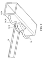
- Figure 2 is an exploded view of one embodiment of the support bracket of the present invention.
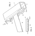
- Figure 3 is a perspective view of another embodiment of the support bracket of the present invention.
- Figure 4 is a front view of yet another embodiment of the support bracket of the present invention.
- Figure 5 is a perspective view of one embodiment of the body support assembly incorporated into a chair.
- Figure 6 is a perspective view of yet another embodiment of the support bracket of the present invention.
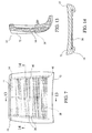
- Figure 7 is a perspective view of one embodiment of the body support assembly incorporated into a seat portion of a chair and encapsulated by a cushion material.
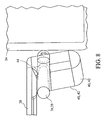
- Figure 8 is a fragmentary view of one embodiment of the support bracket of the present invention.
- Figure 9 is a perspective view of one embodiment of the strap of the present invention.
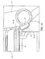
- Figure 10 is a fragmentary view of one embodiment of the body support assembly.
- Figure 11 is a front view of one embodiment of the body support assembly incorporated into a back portion of a chair.
- Figure 12 is a perspective view of one embodiment of the body support assembly incorporated into a seat portion of a chair.
- Figure 13 is a side cross-sectional view of the body support assembly incorporated into a seat portion of a chair shown in Figure 7 as taken along line 13-13.
- Figure 14 is a front cross-sectional view of the body support assembly incorporated into a seat portion of a chair shown in Figure 7 as taken along line 14-14.
- Figure 15 is a side cross-sectional view of the body support assembly incorporated into a back portion of a chair shown in Figure 11 .
- Figure 16 is a front view of one embodiment of the body support assembly incorporated into a back portion of a chair and encapsulated in a cushion material.
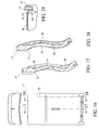
- Figure 17 is a side cross-sectional view of the body support assembly incorporated into a back portion of a chair shown in Figure 16 as taken along tine 17-17.
- Figure 18 is another side cross-sectional view of the body support assembly incorporated into a back portion of a chair shown in Figure 16 as taken along line 18-18.
- Figure 19 is a fragmentary view of one embodiment of the body support assembly.
- Figure 20 is a back view of one embodiment of the body support assembly incorporated into a back portion of a chair and encapsulated in a cushion material.
- Figure 21 is a perspective cross-sectional view of a back portion of a chair encapsulated in a cushion material as shown in Figure 20 as taken along line 21-21.
- Figure 22 is another cross-sectional view of a back portion of a chair encapsulated in a cushion material as shown in Figure 20 as taken along line 22-22.
- Figure 23 is yet another cross-sectional view of a back portion of a chair encapsulated in a cushion material as shown in Figure 20 as taken along the longitudinal axis A.
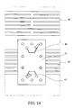
- Figure 24 is another front view of one embodiment of the body support assembly incorporated into a back portion of a chair.
- FIG. 1 A body support assembly 10 according to one embodiment of the present invention is illustrated in FIG. 1 .
- the body support assembly 10 is said to extend in both the X and Y directions, as shown in FIG. 1 .
- the body support assembly 10 generally includes a membrane 11 and a support structure 12.
- the support structure 12, as shown in this embodiment, is a frame having spaced apart frame members 14 which define an opening 16.
- the body support assembly 10 can form part of a back or seat, e.g. of a chair 13, a bed, or any other body support assembly.
- a seat portion 15 and a back portion 17 form part of a chair 13.
- the body support assembly 10 may form part of the back portion 17, as shown in FIG. 11 .
- a continuous frame member 14 supports a membrane 11 disposed across the opening 16.
- Figure 15 is a cross-sectional side view taken along the line 15-15 of the back portion 17 of the chair 13 of Figure 11 .
- the frame member 14 may have a wave-like shape to fit the contour of the user's spine.
- the body support assembly 10 may also form part of the seat portion 14, with an arrangement of a plurality of frame members 14 forming the opening 16.
- the membrane 11 is disposed across the opening 16, and may be encapsulated, as shown in FIG. 7 , by a cushion material, such as foam 72.
- the opposing frame members 14 are generally parallel to one another. However, such an orientation is not necessary, and the support structure 12 may have more or less frame members 14 than as illustrated in FIG. 1 .
- the support structure 12 may be configured as a single, integrally formed frame member 14 as shown in FIG. 11 , or be formed from a plurality of separate frame members 14.
- the support structure 12 has a first frame member 18 which is substantially parallel to a second frame member 20, and a third frame member 22 substantially parallel to a fourth frame member 24.
- the first and second frame members 18, 20 are generally perpendicular to the third and fourth frame members 22, 24.
- the frame members 14 may be attached to one another through conventional attachment devices, including without limitation, welding, adhesives, mechanical fasteners, or the like, and combinations thereof.
- first and second frame members 18, 20 have a generally rectangular cross-section, and may be made out of a metal, wood, composite, alloy, or any other suitable material.
- the size and cross-sectional shape of all the frame members 14 may vary.
- a retaining structure 26 is coupled with the first and second frame members 18, 20.
- the retaining structure 26 is formed by a wire 28 forming a plurality of loops 29.
- the cross-section of the wire can be circular, rectangular, oval, triangular, or any other suitable shape.
- the retaining structure 26 is disposed at least partially along the length of the first and second frame members 18, 20.
- the retaining structure 26 may be attached to the first and second frame members 18, 20 through any conventional attachment device, including without limitation, welding, mechanical fasteners, tabs, shape fit, and/or any combination thereof.
- the retaining structure 26 may also be integral with the first and second frame members 18, 20 and form part thereof. Independent of how the retaining structure 26 is formed and/or attached, the retaining structure 26 may be configured as a plurality of independent structures extending along and secured to the frame members 18, 20, or may be configured as one continuous structure, as shown in FIG. 1 .
- the retaining structure 26, configured as the wire 28, is defined by a longitudinal axis A.
- the wire 28 oscillates in a boustrophedonic, or varying, fashion between a first height H1 and a second height H2, as measured from the longitudinal axis A.
- the frame member 14 may not be linear, and in that event, H1 and H2 can be measured from a centerline defined by the curvature of the member 14 instead of the longitudinal axis A.
- the shape of the wire 28 may vary and may not be consistent within a single embodiment.
- the wire 28 may take on a rectangular-shaped pattern, as shown in FIG. 1 , or may alternate between patterns, as shown in FIG. 4 .
- the location of the wire 28 may vary.
- the wire 28 may not be between the first and second members 18, 20 as shown in FIG. 1 , but may be below, above, or on an outside of each respective member 18, 20.
- the wire 28 may be attached to a top 32, a bottom 34, or an exterior 37 of the member 14.
- the pattern and location of the wire 28 may need not be consistent in a single application either, and may vary on a single member 14 or between members 14.
- FIG. 6 illustrates a wire 28 forming one opening 30 on the top 32 and another one on the interior 36 of the member 14.
- the wire 28 has an approximate diameter of 0.10-0.20 inches (0.25-0.51 cm) thick, and forms an opening between the frame member 14 which has a maximum height (H) of approximately 0.30 inches (0.76 cm) and a gap (G) of approximately 2.625 inches (6.668 cm).
- the wire 28 has a minimum bend radius (r) of 0.1 inches (0.254 cm), with a period (P) of approximately 3.5 inches (8.9 cm).
- the specific measurements may vary depending on factors such as the size and shape of the retention portion, anticipated load and the frequency of its application.
- the respective heights, as measured from the longitudinal axis A, need not be equivalent, or consistent, along the length of the first and second frame members 18, 20, so long as the shape of the wire 28 generally defines at least one opening, or aperture 30, between the frame member 14 and the wire 28.
- the shape of the wire 28 forms a series of openings 30 along the length of the first and second members 18, 20, as shown in FIG. 1 .
- the plurality of openings 30 formed on the first member 18 correspond to the plurality of openings 30 formed on the second member 20.
- the configuration of the openings 30, however, may vary and is dependent on the intended application. Indeed, the openings 30 may also be formed within the frame member 14 itself.
- a strap 38 is disposed across the opening 16, and between the first and second frame members 18, 20.
- the strap 38 as better shown in FIGS. 1 and 5 , has a first end 40 and a second end 42.
- the strap 38 may also have a series of elongated apertures 46 formed therein between the first 40 and second 42 ends, as shown in FIGS. 7 , 9 , 11 and 12 .
- an "aperture” may disposed entirely through the strap 38 and form an opening therethrough, or may only be disposed partially through the strap 38 such that the aperture does not form an opening therethrough.
- the elongated apertures 46 reduce the amount of material required to construct each strap 38, without sacrificing its physical characteristics. It can be appreciated that the apertures 46 may be of any shape, such as oval, circular, or the like.
- the apertures 46 may also vary in size, length, and may have asymmetrical or symmetrical patterns.
- the apertures 46 formed within the strap 38 also facilitate the process of encapsulating the straps 38 with a cushion material 72.
- foam openings, or apertures 46 also can be sized and positioned to optimize the stretch and flexibility properties of the straps 38, individually and collectively.
- the size, location and overall configuration of the apertures 46 can be optimized to allow the cushion material 72 to be disposed through the apertures 46 to encase, and secure, the strap 38, or membrane 11, on both faces of the strap 38, or membrane 11.
- straps 38 may have an aperture 46 with a minimum gap for foam encapsulation of 0.250 inches (0.635 cm) wide by 1.50 to 2.75 inches (3.81 to 6.985 cm) long.
- the cushion material 72 functions to lock the crystalline structure, fibers, or filament of the membrane 11, or strap 38, together to provide for the desired distribution of seating loads throughout the membrane 11 and to avoid areas of stress concentration.
- the cushion material 72 also functions to shrink the membrane 11 to further induce tension in the membrane 11 and insure its ability to comfortably resist seating loads.
- the cushion material 72 can be of any suitable foam material such as a urethane foam.
- the cushion material 72 may encapsulate, and form part of, the seat 15 as shown in FIGS. 7, 13, and 14.
- Figure 7 illustrates a perspective front view of the cushion material 72 disposed substantially around the membrane 11.
- Figures 13 and 14 represent the cross-sectional views of the seat 15 shown in FIG. 7 taken along the 13-13 and 14-14 lines, respectively.
- the cushion material 72 may also encapsulate, and form part of, the back 17 as shown in FIGS. 16 - 18 . As shown in FIG. 16 , the cushion material 72 covers substantially the entire membrane 11. Figures 17 and 18 are cross-sectional views taken along lines 17-17 and 18-18, respectively, which illustrate the membrane 11 being substantially covered by the cushion material 72.
- the cushion material 72 may also contain one or more relief channels 74 formed within the surface of the cushion material 72.
- FIG. 20 also depicts the straps 38 and apertures 46 in dashed lines and one embodiment of their respective locations with respect to the relief channels 74.
- the relief channels 74 reduce the restrictive nature of the cushion material 72 when a load is applied and permits the membrane 11 to react more freely in response to the load.
- the relief channels 74 break the surface tension of the cushion material 72, and permit the cushion-encapsulated membrane 11 to behave in a manner more similar to a non-capsulated membrane 11, thereby increasing the amount of deflection exhibited by the membrane 11.
- multiple relief channels 74 may be formed within the surface of the cushion material 72, and may be incorporated into any portion, or surface, of any body support assembly.
- the relief channels 74 may be positioned anywhere along the cushion material and may be placed in locations requiring greater deflection to provide enhanced comfort.
- an upper set of relief channels 76 may be positioned at a location corresponding to user's upper back, specifically at the t10/t12 spine vertebra and a center relief channel 78 may be disposed along the centerline of the cushion material 72, along the longitudinal axis A which corresponds to the user's spinal column.
- Figure 22 is a cross-sectional view of FIG. 20 taken along line 22-22, which shows the spatial relationship with respect to the upper set of relief channels 76 and the center relief channel 78.
- Figure 23 is a cross-sectional view of the center relief channel 78 taken along the longitudinal axis A as shown in FIG. 20 .
- the straps 38 run along the X direction and the channels 74 are transverse, for example substantially perpendicular, to the straps 38 of the membrane 11.
- the straps 38 may run in any other direction, such as the Y direction, and the channels 74 may be orientated in any other direction or angle relative to the straps 38, such as being parallel to the straps 38.
- the relief channels 74 may be disposed in any direction with respect to the longitudinal axis A, and may be connected to one another to form a relief zone.
- a lower set of relief channels 84 form a rectangle 80 at the lumbar portion of the user's back.
- FIG. 21 which is a perspective cross-sectional view of FIG. 20 taken along line 21-21, and FIG. 23 better illustrate how the center relief channel 78 is connected to the lower set of relief channels 84.
- the location of the rectangle 80 forms a lumbar zone 82, which corresponds to the location of a passive lumbar member 41 of the back portion 17 of the chair 13, as shown in FIG. 11 .
- the lumbar zone 82 allows for the increased deflection, and response to a load, by the membrane 11.
- the dimensions of the relief channels 74 may vary; however in one embodiment, the relief channels 74 have a width of approximately 7 mm, with the upper relief channels 76 each having a length of approximately 155 mm and are located approximately 90 mm away from the longitudinal axis A in the X direction.
- the center relief channel 78, located along the longitudinal axis A, may have a width of approximately 7 mm and a length of approximately 310 mm.
- the area of the rectangle 80 formed by the relief channels 72 may have an approximate width of 105 mm and an approximate height of 151 mm along the longitudinal axis A.
- the depth of the relief channels 74 is such that there is approximately 12 mm of foam between the bottom of the channel 74 and the membrane 11.
- the depth of the relief channels 74 may further vary such that there is anywhere between 5 to 20 mm of foam between the bottom of the channel 74 and the membrane 11. In another embodiment, the depth of the relief channel 74 may range from 10 to 15 mm of foam between the bottom of the channel 74 and the membrane 11. Alternatively, the depth of the relief channels 74 may also be equal of the thickness of the cushion material 72, and therefore may form an aperture completely through the cushion material 72, or may be equal to half of the thickness of the cushion material 72 and therefore may form an aperture up to the membrane 11.
- the apertures 46 permit a specific amount of extension of the strap 38, or membrane 11, in the desired direction without significant stretching of the strap 38, or membrane 11.
- the apertures 46 may be elongated as shown in FIGS. 7 , 9 , and 12 and may be staggered across each strap 38 or membrane 11, with the precise shape, number, location, and size of the apertures 46 being dictated primarily by the desired support characteristics.
- the strap 38 may be molded with a bead around each aperture 46 to reduce the possibility of tearing.
- first and second ends 40, 42 generally extend downward and are configured to fit within the openings 30 formed by the wire 28, such that the strap 38 spans at least partially across the opening 16.
- the first and second ends 40, 42 are also known as retention portions, which are configured to retain the strap 38 within the opening 30 formed by the wire 28.
- the ends 40, 42 of the strap 38 may take on a shape similar to that of the opening 30, and therefore may have a rectangular shape, semi-spherical shape, or the like.
- the membrane 11 is generally formed through the use of multiple straps 38 spanning at least partially across the opening 16, as shown in FIG. 1 .
- the membrane 11 may be formed as a single integral member extending across the opening 16 of the support structure 12 having a series of retention portions 40, 42 disposed along the unitary membrane 11.
- the straps 38 can span in one or both of the X and Y directions.
- the straps 38 in the embodiment shown in FIG. 1 , are generally adjacent to, and parallel with, one another. It can be appreciated that the number, orientation, size, and shape of the straps 38 may vary and is application dependent.
- the embodiment in FIG. 1 includes seven straps 38 disposed across the opening 16.
- the membrane 11 is formed from five straps 38 disposed across the opening 16 in the X direction.
- the membrane 11 forms part of the back portion 17 of the chair 13, where the lowermost strap 39 is coupled with the passive lumbar member 41.
- the passive lumbar member 41 has two tabs 43 which connect the member 41 to a portion of the lowermost strap 39.
- the passive lumber member 41 may be secured to the lowermost strap 39 by any other suitable means, such as adhesive or any suitable mechanical fasteners, such as a nut and bolt configuration.
- the passive lumbar member 41 is meant to pivot with the strap 39 and provides support to the lumbar portion of the user's back.
- the third lowermost strap 47 is specifically positioned along the frame members 14 to provide comfort to the user's upper back, specifically at the t10/t12 spine vertebras.
- the straps 38 of the membrane 11 are molded from a thermoplastic polyether ester elastomer block copolymer. Suitable materials of this type include that available from DuPont under the Hytrel ® trademark, and that are available from DSM under the Arnitel ® trademark. A variety of alternative elastomers may be suitable for use in the present invention.
- the thickness of the molded membrane 11 will vary from application to application, depending primarily on the anticipated load and the desired stiffness of the surface. In standard seating applications, the support portion of the membrane 11 may have an average thickness prior to any desired orientating of approximately 20-40 mils.
- the strap(s) 38 forming the molded membrane 11 is orientated in one direction (i.e.
- membrane 11 may mean an individual strap 38 or plurality of straps 38 which can be orientated in different arrangements.
- the membrane 11 is orientated by increasing the alignment of the crystalline structure of the elastomeric membrane 11 on a molecular level so that its support and other load baring characteristics are altered.
- the membrane 11 is orientated to such a degree that the orientated membrane 11 has a materially different load bearing characteristics in the orientated direction than in other directions.
- One method for orientating the membrane 11 is through stretching.
- the amount of stretch required to obtain the desired alignment will vary from application to application, but in most applications the desired degree of alignment will occur when the membrane 11 is stretched to roughly two times its original dimension.
- the elastomeric membrane 11 may be orientated by stretching the membrane 11, it may be possible in some applications to orient the membrane 11 using other processes. For example, it may be possible to orient certain material by hammering or other forms of compressions rather than stretching the membrane 11.
- many elastomeric materials, including molded Hytrel® have essentially no elasticity and are susceptible to a high degree of creep when in a molded form.
- the orientation process causes a significant change in the properties of the elastomeric material. For example, orientation of the membrane 11 increases the elasticity of the material and decreases its inherent susceptibility to creep.
- the elastomeric membrane 11, or each strap 38 is molded using conventional techniques and apparatus.
- the elastomeric membrane 11 may be injection molded using a conventional injection molding apparatus having a die that is configured to provide a membrane with the desired shape and features.
- the elastomeric membrane 11 is manufactured by injecting the desired material into the die cavity.
- the die is designed to provide a molded blank that will take on the desired shape once any desired orientation has taken place.
- the dies are configured to form a part that will have the desired shape and dimensions after the orientation step is complete.
- the membrane 11, or each individual strap 38 may be stretched or otherwise orientated in one direction.
- the precise amount of stretch to be applied to a given membrane 11, or strap 38 will depend on the configuration of the membrane 11 and the desired support characteristics. In many applications, it will be necessary to stretch the membrane to at least twice its original length to achieve the desired alignment.
- the membrane 11 may be stretched using conventional techniques and apparatuses. As a result of the increase in alignment of the crystalline structure, the membrane 11, or each strap 38, will not fully return to its original length after being released from the stretching equipment. Rather, the orientated membrane 11 will be elongated a certain portion of the stretched distance, with the precise amount of elongation being dependent in part on the material characteristics of the membrane material. Once any desired orientation has taken place, the membrane 11 can be mounted directly to the support structure as described herein.
- the membrane 11 may be orientated by compression.
- the membrane 11, or each strap 38 is placed in a die or other structure that constrains the membrane 11 on all sides other than at least one side that corresponds with the desired direction of orientation. Opposed sides may be unconstrained to permit the material of the membrane 11 to flow from both sides along the direction of orientation. Alternatively, only a single side may be constrained, thereby limiting material flow to a single side.
- a compressive force is then applied to the membrane 11.
- a press can be used to compress the membrane 11 within the die. Sufficient compressive force is applied so that the material begins to flow in the unconstrained direction.
- each individual strap 38 forming the membrane 11, if more than one strap 38 exists, may be individually orientated. Moreover, in some applications, it may be desirable to orient only select peripheral portions of the membrane 11 or strap 38. When desirable, this may be achieved by applying localized stretching or localized compression of the membrane 11 or each strap 38.
- the straps 38 each have a generally rectangular cross-section as shown in FIG. 8 .
- the first and second ends 40, 42 of the strap 38 define a recessed portion 44 having a shape, e.g. concave, complimentary to that of the wire 28, e.g. curved, such that a portion of the wire 28 can be seated within the recessed portion 44 of the strap 38.
- the recessed portion 44 helps secure the strap 38 to the member 14.
- the retaining portions 40, 42 have a larger cross-sectional area than that of opening 30 of the wire 28 to ensure a secure fit.
- the ends 40, 42 of the strap 38 may have an enlarged portion 45, which secures the wire 28 within each respective end 40, 42.
- the enlarged portion 45 has a first side 52 that is adjacent to the frame member 14, as shown in FIGS. 10 and 19 .
- each strap 38 deflects in the direction of the force.
- the degree of deflection is, at least in part, governed by the physical characteristics of the strap 38 and the amount of applied force.
- One way to control the degree of deflection is by changing the thickness and shape of the enlarged portion 45.
- the wire 28 acts like a pivot point when a force is applied to the membrane 11, which causes the ends 40, 42 of each strap 38 to rotate about the loop, or wire 28, and displace in a direction opposite from the direction of the force.
- the ends 40, 42 will pivot with respect to the wire 28, but will not decouple from the wire 28.
- the geometry of the portion 45 is such that the first side 52 is adjacent to, and in contact with, the frame member 14, the opposing reactive force exerted on the enlarged portion 45 by the frame member 14 will limit the rotation of the ends 40, 42, and resulting degree of deflection of the strap 38.
- the degree of deflection can be modified. It is also contemplated that the magnitude and location of the reaction and opposing forces will be governed, in part, by the specific geometry of the strap 38 and the connecting member 16.
- the ends 40, 42 of the strap 38 are further locked to, or wedged within, the aperture 30 formed by the wire 28 as the strap 38 is stretched across the opening 16.
- the axial forces, along the X direction, resulting from the stretching process cause the ends 40, 42 of the strap 38 to wedge itself against the frame member 14 and the wire 28, thereby resulting in a more secure connection between the strap 38 and the frame member 14.
- the stretching of the strap 38 causes the end 40 to pivot about the wire 28 and cause the end 40 to wedge between the frame member 14 and the wire 28.
- the wedging of the ends 40, 42 of the strap 38 between the wire 28 and the frame member 14 can be accomplished independent of whether the recessed portion 44 is present for that particular embodiment.
- the wire 28 may be located on the top, bottom, interior, or exterior sides 32, 34, 36, 37 of the member 14. Accordingly, the ends 40, 42 of the strap 38 must have a conforming geometry.
- the first end 40 is configured to couple with the wire 18 coupled to the bottom side 36 of the frame member 14, and the second end 42 of the strap 38 is configured to couple with a wire 28 which is located on the top 32 of the member 14.
- the location of the recessed portion 44 of the strap 38 is also application dependent.
Landscapes
- Mattresses And Other Support Structures For Chairs And Beds (AREA)
- Chair Legs, Seat Parts, And Backrests (AREA)
Description
- This application claims the benefit of
U.S. Provisional Application No. 61/101,423, filed September 30, 2008 U.S. Provisional Application No. 61/058,783, filed June 4, 2008 - The present invention relates to body support assemblies, and more particularly, to a load bearing assembly creating a body support assembly over an opening defined by a support structure, such as the seat or back of a chair or bench, or a support surface of a bed, cot or other similar structure.
- There are continuing efforts to develop new and improved load bearing assemblies. One of the objectives of these assemblies is to create a durable and inexpensive body support assembly that is relatively easy to manufacture and that can be easily attached to a support structure. For example, the load bearing assemblies can be configured with a suspension member, such as a membrane, or series of straps, which support the body of the user.
GB 1,360,375 - Load bearing support surfaces that currently exist generally have a linear force/deflection profile, which gives the body support assembly the feel of a drum or trampoline. In seating or other support-based applications, this may result in an uncomfortable and sometimes ergonomically unacceptable body support assembly. In some applications, the body support assembly is encapsulated by a foam or embedded in another structure to compensate for these deficiencies. However, the ability to tune the physical characteristics of a conventional molded seat is relatively limited and difficult to predict. Different materials and different material thicknesses can be used to add a limited degree of control over the characteristics of the seat, but this nominal level of control may not be adequate in many applications.
- Conventional attachment mechanisms such as screws, adhesives, or the like may be utilized to attach the suspension members to the support structure. However, such mechanisms may be problematic because of the extra costs and time associated with additional materials and manufacturing steps. Accordingly, there continues to be a desire for providing a secure attachment mechanism for attaching the suspension member, or other support surfaces, to the support structure.
- In accordance with the present invention, there is provided a body support structure according to
claim 1. - In one embodiment a body support assembly includes a pair of spaced a pair of spaced apart frame members defining an opening therebetween, where at least one of the frame members comprises a plurality of loops spaced along the frame, where each of the loops defines an aperture and an elastomeric member extending across the opening between the pair of spaced apart members, where the elastomer member comprises a retention portion disposed through the aperture.
- In another embodiment the load bearing structure includes a pair of spaced apart frame members defining an opening therebetween where the pair of frame members comprises a plurality of continuous loops spaced along each frame member, where each of the loops defines an aperture and an elastomeric member extending across the opening between the pair of spaced apart frame members, where the elastomeric member comprises a first end having a first retention portion forming part thereof, the first retention portion being disposed through one of the plurality of loops on one of the pair of spaced apart frame members, and a second end having a second retention portion forming part thereof, the second retention portion being disposed through one of the plurality of loops on the other of the pair of spaced apart frame members.
- There is also described a method of manufacturing a body support assembly that includes providing a pair of spaced apart frame members, which defines an opening, at least one loop, and an elastomeric member, attaching the elastomeric member to one of the spaced apart frame members by inserting a retention portion of the elastomeric member through the at least one loop, stretching the elastomeric member across the opening, and attaching the elastomeric member to the other of the spaced apart frame members.
- There is also described a method of use of a body support assembly that includes providing an elastomeric member stretched across a pair of spaced apart frame members, where the elastomeric members have a retention portion coupled to one of a plurality of loops spaced along the frame, applying a load to the elastomeric member, stretching the elastomeric member, and rotating the retention portion with respect to the frame members without decoupling the retention portion from the loop.
- In yet another embodiment, a body support assembly comprises a pair of spaced apart frame members defining an opening therebetween, an elastomeric member extending across the opening between the pair of spaced apart members, where the elastomeric member is connected to the frame members, a cushion material configured to at least partially encapsulate the elastomeric member, and a relief channel formed within the cushion material.
- There is also described a method of manufacturing a body support that comprises providing a pair of spaced apart frame members which define an opening and an elastomeric member, encapsulating the elastomeric member with a cushion material, forming at least one relief channel within the cushion material, and securing the elastomeric member across the opening between the pair of spaced apart frame members.
- The foregoing paragraphs have been provided by way of introduction, and are not intended to limit the scope of the following claims. The various preferred embodiments, together with further advantages, will be best understood by reference to the following detailed description taken in conjunction with the accompanying drawings.
-
Figure 1 is a perspective view of one embodiment of the body support assembly. -
Figure 2 is an exploded view of one embodiment of the support bracket of the present invention. -
Figure 3 is a perspective view of another embodiment of the support bracket of the present invention. -
Figure 4 is a front view of yet another embodiment of the support bracket of the present invention. -
Figure 5 is a perspective view of one embodiment of the body support assembly incorporated into a chair. -
Figure 6 is a perspective view of yet another embodiment of the support bracket of the present invention. -
Figure 7 is a perspective view of one embodiment of the body support assembly incorporated into a seat portion of a chair and encapsulated by a cushion material. -
Figure 8 is a fragmentary view of one embodiment of the support bracket of the present invention. -
Figure 9 is a perspective view of one embodiment of the strap of the present invention. -
Figure 10 is a fragmentary view of one embodiment of the body support assembly. -
Figure 11 is a front view of one embodiment of the body support assembly incorporated into a back portion of a chair. -
Figure 12 is a perspective view of one embodiment of the body support assembly incorporated into a seat portion of a chair. -
Figure 13 is a side cross-sectional view of the body support assembly incorporated into a seat portion of a chair shown inFigure 7 as taken along line 13-13. -
Figure 14 is a front cross-sectional view of the body support assembly incorporated into a seat portion of a chair shown inFigure 7 as taken along line 14-14. -
Figure 15 is a side cross-sectional view of the body support assembly incorporated into a back portion of a chair shown inFigure 11 . -
Figure 16 is a front view of one embodiment of the body support assembly incorporated into a back portion of a chair and encapsulated in a cushion material. -
Figure 17 is a side cross-sectional view of the body support assembly incorporated into a back portion of a chair shown inFigure 16 as taken along tine 17-17. -
Figure 18 is another side cross-sectional view of the body support assembly incorporated into a back portion of a chair shown inFigure 16 as taken along line 18-18. -
Figure 19 is a fragmentary view of one embodiment of the body support assembly. -
Figure 20 is a back view of one embodiment of the body support assembly incorporated into a back portion of a chair and encapsulated in a cushion material. -
Figure 21 is a perspective cross-sectional view of a back portion of a chair encapsulated in a cushion material as shown inFigure 20 as taken along line 21-21. -
Figure 22 is another cross-sectional view of a back portion of a chair encapsulated in a cushion material as shown inFigure 20 as taken along line 22-22. -
Figure 23 is yet another cross-sectional view of a back portion of a chair encapsulated in a cushion material as shown inFigure 20 as taken along the longitudinal axis A. -
Figure 24 is another front view of one embodiment of the body support assembly incorporated into a back portion of a chair. - The invention is described with reference to the drawings in which like elements are referred to by like numerals. The relationship and functioning of the various elements of this invention are better understood by the following detailed description. However, the embodiments of this invention as described below are by way of example only, and the invention is not limited to the embodiments illustrated in the drawings.
- A
body support assembly 10 according to one embodiment of the present invention is illustrated inFIG. 1 . For ease of referencing the orientations of components, thebody support assembly 10 is said to extend in both the X and Y directions, as shown inFIG. 1 . Thebody support assembly 10 generally includes amembrane 11 and asupport structure 12. Thesupport structure 12, as shown in this embodiment, is a frame having spaced apartframe members 14 which define anopening 16. Thebody support assembly 10 can form part of a back or seat, e.g. of achair 13, a bed, or any other body support assembly. - For example, as shown in
FIG. 5 , aseat portion 15 and aback portion 17 form part of achair 13. Thebody support assembly 10 may form part of theback portion 17, as shown inFIG. 11 . In this embodiment, acontinuous frame member 14 supports amembrane 11 disposed across theopening 16.Figure 15 is a cross-sectional side view taken along the line 15-15 of theback portion 17 of thechair 13 ofFigure 11 . As shown, theframe member 14 may have a wave-like shape to fit the contour of the user's spine. - Similarly, as shown in
FIGS. 7 and12 , thebody support assembly 10 may also form part of theseat portion 14, with an arrangement of a plurality offrame members 14 forming theopening 16. Themembrane 11 is disposed across theopening 16, and may be encapsulated, as shown inFIG. 7 , by a cushion material, such asfoam 72. - Referring back to
FIG. 1 , the opposingframe members 14 are generally parallel to one another. However, such an orientation is not necessary, and thesupport structure 12 may have more orless frame members 14 than as illustrated inFIG. 1 . Thesupport structure 12 may be configured as a single, integrally formedframe member 14 as shown inFIG. 11 , or be formed from a plurality ofseparate frame members 14. - In one embodiment, the
support structure 12 has afirst frame member 18 which is substantially parallel to asecond frame member 20, and athird frame member 22 substantially parallel to afourth frame member 24. The first andsecond frame members fourth frame members frame members 14 with respect to one another is application dependent. Theframe members 14 may be attached to one another through conventional attachment devices, including without limitation, welding, adhesives, mechanical fasteners, or the like, and combinations thereof. - As further shown in
FIG. 2 , the first andsecond frame members frame members 14 may vary. - Referring back to
FIG. 1 , a retaining structure 26 is coupled with the first andsecond frame members FIG. 12 , the retaining structure 26 is formed by awire 28 forming a plurality ofloops 29. The cross-section of the wire can be circular, rectangular, oval, triangular, or any other suitable shape. The retaining structure 26 is disposed at least partially along the length of the first andsecond frame members second frame members second frame members frame members FIG. 1 . - As shown in
FIG. 3 , the retaining structure 26, configured as thewire 28, is defined by a longitudinal axis A. Thewire 28 oscillates in a boustrophedonic, or varying, fashion between a first height H1 and a second height H2, as measured from the longitudinal axis A. Theframe member 14 may not be linear, and in that event, H1 and H2 can be measured from a centerline defined by the curvature of themember 14 instead of the longitudinal axis A. It can be appreciated that the shape of thewire 28 may vary and may not be consistent within a single embodiment. For example, thewire 28 may take on a rectangular-shaped pattern, as shown inFIG. 1 , or may alternate between patterns, as shown inFIG. 4 . In addition, the location of thewire 28 may vary. By way of example, thewire 28 may not be between the first andsecond members FIG. 1 , but may be below, above, or on an outside of eachrespective member wire 28 may be attached to a top 32, a bottom 34, or anexterior 37 of themember 14. Indeed, the pattern and location of thewire 28 may need not be consistent in a single application either, and may vary on asingle member 14 or betweenmembers 14. For example,FIG. 6 illustrates awire 28 forming oneopening 30 on the top 32 and another one on the interior 36 of themember 14. - In one embodiment, as shown in
FIG. 3 , thewire 28 has an approximate diameter of 0.10-0.20 inches (0.25-0.51 cm) thick, and forms an opening between theframe member 14 which has a maximum height (H) of approximately 0.30 inches (0.76 cm) and a gap (G) of approximately 2.625 inches (6.668 cm). Thewire 28 has a minimum bend radius (r) of 0.1 inches (0.254 cm), with a period (P) of approximately 3.5 inches (8.9 cm). The specific measurements, of course, may vary depending on factors such as the size and shape of the retention portion, anticipated load and the frequency of its application. - It is important to note that the respective heights, as measured from the longitudinal axis A, need not be equivalent, or consistent, along the length of the first and
second frame members wire 28 generally defines at least one opening, oraperture 30, between theframe member 14 and thewire 28. In this embodiment, the shape of thewire 28 forms a series ofopenings 30 along the length of the first andsecond members FIG. 1 . In this embodiment, the plurality ofopenings 30 formed on thefirst member 18 correspond to the plurality ofopenings 30 formed on thesecond member 20. The configuration of theopenings 30, however, may vary and is dependent on the intended application. Indeed, theopenings 30 may also be formed within theframe member 14 itself. - A
strap 38 is disposed across theopening 16, and between the first andsecond frame members strap 38, as better shown inFIGS. 1 and5 , has afirst end 40 and asecond end 42. Thestrap 38 may also have a series ofelongated apertures 46 formed therein between the first 40 and second 42 ends, as shown inFIGS. 7 ,9 ,11 and 12 . As referred to herein, an "aperture" may disposed entirely through thestrap 38 and form an opening therethrough, or may only be disposed partially through thestrap 38 such that the aperture does not form an opening therethrough. Theelongated apertures 46 reduce the amount of material required to construct eachstrap 38, without sacrificing its physical characteristics. It can be appreciated that theapertures 46 may be of any shape, such as oval, circular, or the like. Theapertures 46 may also vary in size, length, and may have asymmetrical or symmetrical patterns. - The
apertures 46 formed within thestrap 38 also facilitate the process of encapsulating thestraps 38 with acushion material 72. For example, and without limitation, foam openings, orapertures 46, also can be sized and positioned to optimize the stretch and flexibility properties of thestraps 38, individually and collectively. The size, location and overall configuration of theapertures 46 can be optimized to allow thecushion material 72 to be disposed through theapertures 46 to encase, and secure, thestrap 38, ormembrane 11, on both faces of thestrap 38, ormembrane 11. In one embodiment, straps 38 may have anaperture 46 with a minimum gap for foam encapsulation of 0.250 inches (0.635 cm) wide by 1.50 to 2.75 inches (3.81 to 6.985 cm) long. Thecushion material 72 functions to lock the crystalline structure, fibers, or filament of themembrane 11, orstrap 38, together to provide for the desired distribution of seating loads throughout themembrane 11 and to avoid areas of stress concentration. Thecushion material 72 also functions to shrink themembrane 11 to further induce tension in themembrane 11 and insure its ability to comfortably resist seating loads. Thecushion material 72 can be of any suitable foam material such as a urethane foam. - The
cushion material 72 may encapsulate, and form part of, theseat 15 as shown inFIGS. 7, 13, and 14. Figure 7 illustrates a perspective front view of thecushion material 72 disposed substantially around themembrane 11.Figures 13 and 14 represent the cross-sectional views of theseat 15 shown inFIG. 7 taken along the 13-13 and 14-14 lines, respectively. - Similarly, the
cushion material 72 may also encapsulate, and form part of, the back 17 as shown inFIGS. 16 - 18 . As shown inFIG. 16 , thecushion material 72 covers substantially theentire membrane 11.Figures 17 and 18 are cross-sectional views taken along lines 17-17 and 18-18, respectively, which illustrate themembrane 11 being substantially covered by thecushion material 72. - In an alternative embodiment, as shown in
FIG. 20 , thecushion material 72 may also contain one or more relief channels 74 formed within the surface of thecushion material 72. For completeness,FIG. 20 also depicts thestraps 38 andapertures 46 in dashed lines and one embodiment of their respective locations with respect to the relief channels 74. The relief channels 74 reduce the restrictive nature of thecushion material 72 when a load is applied and permits themembrane 11 to react more freely in response to the load. In other words, the relief channels 74 break the surface tension of thecushion material 72, and permit the cushion-encapsulatedmembrane 11 to behave in a manner more similar to anon-capsulated membrane 11, thereby increasing the amount of deflection exhibited by themembrane 11. As shown inFIG. 20 , multiple relief channels 74 may be formed within the surface of thecushion material 72, and may be incorporated into any portion, or surface, of any body support assembly. - The relief channels 74 may be positioned anywhere along the cushion material and may be placed in locations requiring greater deflection to provide enhanced comfort. For example, in one embodiment, as shown in
FIGS. 20 and22 , an upper set ofrelief channels 76 may be positioned at a location corresponding to user's upper back, specifically at the t10/t12 spine vertebra and acenter relief channel 78 may be disposed along the centerline of thecushion material 72, along the longitudinal axis A which corresponds to the user's spinal column.Figure 22 is a cross-sectional view ofFIG. 20 taken along line 22-22, which shows the spatial relationship with respect to the upper set ofrelief channels 76 and thecenter relief channel 78.Figure 23 is a cross-sectional view of thecenter relief channel 78 taken along the longitudinal axis A as shown inFIG. 20 . In this embodiment, thestraps 38 run along the X direction and the channels 74 are transverse, for example substantially perpendicular, to thestraps 38 of themembrane 11. However, thestraps 38 may run in any other direction, such as the Y direction, and the channels 74 may be orientated in any other direction or angle relative to thestraps 38, such as being parallel to thestraps 38. - The relief channels 74 may be disposed in any direction with respect to the longitudinal axis A, and may be connected to one another to form a relief zone. For example, as further shown in
FIGS. 20 and21 , a lower set ofrelief channels 84 form arectangle 80 at the lumbar portion of the user's back. Specifically,FIG. 21 , which is a perspective cross-sectional view ofFIG. 20 taken along line 21-21, andFIG. 23 better illustrate how thecenter relief channel 78 is connected to the lower set ofrelief channels 84. The location of therectangle 80 forms alumbar zone 82, which corresponds to the location of a passivelumbar member 41 of theback portion 17 of thechair 13, as shown inFIG. 11 . Thelumbar zone 82 allows for the increased deflection, and response to a load, by themembrane 11. - The dimensions of the relief channels 74 may vary; however in one embodiment, the relief channels 74 have a width of approximately 7 mm, with the
upper relief channels 76 each having a length of approximately 155 mm and are located approximately 90 mm away from the longitudinal axis A in the X direction. Thecenter relief channel 78, located along the longitudinal axis A, may have a width of approximately 7 mm and a length of approximately 310 mm. The area of therectangle 80 formed by therelief channels 72 may have an approximate width of 105 mm and an approximate height of 151 mm along the longitudinal axis A. The depth of the relief channels 74 is such that there is approximately 12 mm of foam between the bottom of the channel 74 and themembrane 11. Additionally, the depth of the relief channels 74 may further vary such that there is anywhere between 5 to 20 mm of foam between the bottom of the channel 74 and themembrane 11. In another embodiment, the depth of the relief channel 74 may range from 10 to 15 mm of foam between the bottom of the channel 74 and themembrane 11. Alternatively, the depth of the relief channels 74 may also be equal of the thickness of thecushion material 72, and therefore may form an aperture completely through thecushion material 72, or may be equal to half of the thickness of thecushion material 72 and therefore may form an aperture up to themembrane 11. - The
apertures 46 permit a specific amount of extension of thestrap 38, ormembrane 11, in the desired direction without significant stretching of thestrap 38, ormembrane 11. Theapertures 46 may be elongated as shown inFIGS. 7 ,9 , and12 and may be staggered across eachstrap 38 ormembrane 11, with the precise shape, number, location, and size of theapertures 46 being dictated primarily by the desired support characteristics. Thestrap 38 may be molded with a bead around eachaperture 46 to reduce the possibility of tearing. - In the embodiment shown in
FIG. 2 , the first and second ends 40, 42 generally extend downward and are configured to fit within theopenings 30 formed by thewire 28, such that thestrap 38 spans at least partially across theopening 16. The first and second ends 40, 42 are also known as retention portions, which are configured to retain thestrap 38 within theopening 30 formed by thewire 28. In one embodiment, the ends 40, 42 of thestrap 38 may take on a shape similar to that of theopening 30, and therefore may have a rectangular shape, semi-spherical shape, or the like. Themembrane 11 is generally formed through the use ofmultiple straps 38 spanning at least partially across theopening 16, as shown inFIG. 1 . However, themembrane 11 may be formed as a single integral member extending across theopening 16 of thesupport structure 12 having a series ofretention portions unitary membrane 11. Independent of the configuration, thestraps 38 can span in one or both of the X and Y directions. - The
straps 38, in the embodiment shown inFIG. 1 , are generally adjacent to, and parallel with, one another. It can be appreciated that the number, orientation, size, and shape of thestraps 38 may vary and is application dependent. For example, the embodiment inFIG. 1 includes sevenstraps 38 disposed across theopening 16. In another example, shown inFIG. 11 , themembrane 11 is formed from fivestraps 38 disposed across theopening 16 in the X direction. In this particular embodiment, themembrane 11 forms part of theback portion 17 of thechair 13, where thelowermost strap 39 is coupled with the passivelumbar member 41. As shown inFIG. 24 , the passivelumbar member 41 has twotabs 43 which connect themember 41 to a portion of thelowermost strap 39. Thepassive lumber member 41 may be secured to thelowermost strap 39 by any other suitable means, such as adhesive or any suitable mechanical fasteners, such as a nut and bolt configuration. The passivelumbar member 41 is meant to pivot with thestrap 39 and provides support to the lumbar portion of the user's back. The thirdlowermost strap 47 is specifically positioned along theframe members 14 to provide comfort to the user's upper back, specifically at the t10/t12 spine vertebras. - In the illustrated embodiment, the
straps 38 of themembrane 11 are molded from a thermoplastic polyether ester elastomer block copolymer. Suitable materials of this type include that available from DuPont under the Hytrel® trademark, and that are available from DSM under the Arnitel® trademark. A variety of alternative elastomers may be suitable for use in the present invention. The thickness of the moldedmembrane 11 will vary from application to application, depending primarily on the anticipated load and the desired stiffness of the surface. In standard seating applications, the support portion of themembrane 11 may have an average thickness prior to any desired orientating of approximately 20-40 mils. In one embodiment, the strap(s) 38 forming the moldedmembrane 11 is orientated in one direction (i.e. the X direction) to provide creep resistance and elasticity in the direction of orientation. For ease of reference, it is contemplated that the term "membrane" 11 may mean anindividual strap 38 or plurality ofstraps 38 which can be orientated in different arrangements. Themembrane 11 is orientated by increasing the alignment of the crystalline structure of theelastomeric membrane 11 on a molecular level so that its support and other load baring characteristics are altered. Typically, themembrane 11 is orientated to such a degree that the orientatedmembrane 11 has a materially different load bearing characteristics in the orientated direction than in other directions. - One method for orientating the
membrane 11 is through stretching. The amount of stretch required to obtain the desired alignment will vary from application to application, but in most applications the desired degree of alignment will occur when themembrane 11 is stretched to roughly two times its original dimension. Although theelastomeric membrane 11 may be orientated by stretching themembrane 11, it may be possible in some applications to orient themembrane 11 using other processes. For example, it may be possible to orient certain material by hammering or other forms of compressions rather than stretching themembrane 11. It should be noted that many elastomeric materials, including molded Hytrel®, have essentially no elasticity and are susceptible to a high degree of creep when in a molded form. The orientation process causes a significant change in the properties of the elastomeric material. For example, orientation of themembrane 11 increases the elasticity of the material and decreases its inherent susceptibility to creep. - As noted above, the
elastomeric membrane 11, or eachstrap 38, is molded using conventional techniques and apparatus. For example, theelastomeric membrane 11 may be injection molded using a conventional injection molding apparatus having a die that is configured to provide a membrane with the desired shape and features. In this embodiment, theelastomeric membrane 11 is manufactured by injecting the desired material into the die cavity. The die is designed to provide a molded blank that will take on the desired shape once any desired orientation has taken place. For example, the dies are configured to form a part that will have the desired shape and dimensions after the orientation step is complete. After molded, themembrane 11, or eachindividual strap 38, may be stretched or otherwise orientated in one direction. If orientation is achieved through stretching, the precise amount of stretch to be applied to a givenmembrane 11, orstrap 38, will depend on the configuration of themembrane 11 and the desired support characteristics. In many applications, it will be necessary to stretch the membrane to at least twice its original length to achieve the desired alignment. Themembrane 11 may be stretched using conventional techniques and apparatuses. As a result of the increase in alignment of the crystalline structure, themembrane 11, or eachstrap 38, will not fully return to its original length after being released from the stretching equipment. Rather, the orientatedmembrane 11 will be elongated a certain portion of the stretched distance, with the precise amount of elongation being dependent in part on the material characteristics of the membrane material. Once any desired orientation has taken place, themembrane 11 can be mounted directly to the support structure as described herein. Various aligned materials and structures are disclosed inU.S. Publication No. 2005/0279591, published December 22, 2005 ,U.S. Publication No. 2006/0267258, published November 30, 2006 , andU.S. Publication No. 2006/0286359, published December 21, 2006 . - As an alternative to stretching, the
membrane 11 may be orientated by compression. In one embodiment, themembrane 11, or eachstrap 38, is placed in a die or other structure that constrains themembrane 11 on all sides other than at least one side that corresponds with the desired direction of orientation. Opposed sides may be unconstrained to permit the material of themembrane 11 to flow from both sides along the direction of orientation. Alternatively, only a single side may be constrained, thereby limiting material flow to a single side. A compressive force is then applied to themembrane 11. For example, a press can be used to compress themembrane 11 within the die. Sufficient compressive force is applied so that the material begins to flow in the unconstrained direction. This, in effect, causes themembrane 11 to extend and its crystalline structure to become increasing aligned in the direction of orientation. The amount of force applied to themembrane 11 may vary from application depending on the desired degree of alignment or orientation. Eachindividual strap 38 forming themembrane 11, if more than onestrap 38 exists, may be individually orientated. Moreover, in some applications, it may be desirable to orient only select peripheral portions of themembrane 11 orstrap 38. When desirable, this may be achieved by applying localized stretching or localized compression of themembrane 11 or eachstrap 38. - In one embodiment, the
straps 38 each have a generally rectangular cross-section as shown inFIG. 8 . In addition, as shown inFIGS. 2 and8 , the first and second ends 40, 42 of thestrap 38 define a recessedportion 44 having a shape, e.g. concave, complimentary to that of thewire 28, e.g. curved, such that a portion of thewire 28 can be seated within the recessedportion 44 of thestrap 38. The recessedportion 44 helps secure thestrap 38 to themember 14. In this embodiment, the retainingportions wire 28 to ensure a secure fit. - As shown in
FIGS. 9 ,10 , and19 theends strap 38 may have anenlarged portion 45, which secures thewire 28 within eachrespective end enlarged portion 45 has afirst side 52 that is adjacent to theframe member 14, as shown inFIGS. 10 and19 . When a load is applied to themembrane 11, eachstrap 38 deflects in the direction of the force. The degree of deflection is, at least in part, governed by the physical characteristics of thestrap 38 and the amount of applied force. One way to control the degree of deflection is by changing the thickness and shape of theenlarged portion 45. Thewire 28 acts like a pivot point when a force is applied to themembrane 11, which causes theends strap 38 to rotate about the loop, orwire 28, and displace in a direction opposite from the direction of the force. The ends 40, 42 will pivot with respect to thewire 28, but will not decouple from thewire 28. If the geometry of theportion 45 is such that thefirst side 52 is adjacent to, and in contact with, theframe member 14, the opposing reactive force exerted on theenlarged portion 45 by theframe member 14 will limit the rotation of theends strap 38. By changing the geometry of theenlarged portion 45, the thickness of thewire 28, or the spacing between the loops of thewire 28, the degree of deflection can be modified. It is also contemplated that the magnitude and location of the reaction and opposing forces will be governed, in part, by the specific geometry of thestrap 38 and the connectingmember 16. - As shown in the embodiment in
FIG. 8 , the ends 40, 42 of thestrap 38 are further locked to, or wedged within, theaperture 30 formed by thewire 28 as thestrap 38 is stretched across theopening 16. The axial forces, along the X direction, resulting from the stretching process cause the ends 40, 42 of thestrap 38 to wedge itself against theframe member 14 and thewire 28, thereby resulting in a more secure connection between thestrap 38 and theframe member 14. Specifically, the stretching of thestrap 38 causes theend 40 to pivot about thewire 28 and cause theend 40 to wedge between theframe member 14 and thewire 28. The wedging of theends strap 38 between thewire 28 and theframe member 14 can be accomplished independent of whether the recessedportion 44 is present for that particular embodiment. - As explained above, the
wire 28 may be located on the top, bottom, interior, orexterior sides member 14. Accordingly, the ends 40, 42 of thestrap 38 must have a conforming geometry. For example, thefirst end 40 is configured to couple with thewire 18 coupled to thebottom side 36 of theframe member 14, and thesecond end 42 of thestrap 38 is configured to couple with awire 28 which is located on the top 32 of themember 14. Of course, the location of the recessedportion 44 of thestrap 38 is also application dependent. - Although the present invention has been described with reference to preferred embodiments, those skilled in the art will recognize that changes may be made and formed in detail without departing from the scope of the invention. It is therefore intended that the foregoing detailed description be regarded as illustrative rather than limiting, and that it be understood that it is the following claims, including all equivalents, that are intended to define the scope of this invention.
Claims (18)
- A body support assembly (10) comprising:a pair of spaced apart frame members (14) defining an opening (16) therebetween, at least one of the frame members (14) comprising a plurality of loops (26) spaced along the frame member (14), each of the loops (26) defining an aperture (30); andan elastomeric strap (38) extending across the opening (16) between the pair of spaced apart frame members (14), the elastomeric strap (38) comprising a retention portion (40, 42) disposed through one of the apertures (30), wherein the retention portion (40, 42) comprises a groove (44) with a shape complimentary to that of one of the loops (26), and wherein a portion of the loop (26) is seated within the groove (44) of the retention portion (40, 42).
- The body support assembly (10) of claim 1 wherein the plurality of loops (26) are separate from at least one of the frame members (14).
- The body support assembly (10) of claim 1 wherein the plurality of loops (26) are integral with at least one of the frame members (14).
- The body support assembly (10) of claim 1 wherein the plurality of loops (26) are distinct from one another.
- The body support assembly (10) of claim 1 wherein the plurality of loops (26) are formed from a continuous wire (28).
- The body support assembly (10) of claim 1 wherein the elastomeric strap (38) comprises at least one aperture (46) disposed therethrough.
- The body support assembly (10) of claim 6 wherein a cushion material (72) encapsulates at least a portion of the elastomeric strap (38).
- The body support assembly (10) of claim 1 wherein a plurality of loops (26) are spaced along both of the spaced apart frame members (14).
- The body support assembly (10) of claim 8 wherein a plurality of elastomeric straps (38) extend across the opening (16) between the pair of spaced apart frame members (14).
- The body support assembly of claim 9 wherein a portion of at least one of the elastomeric straps (38) is disposed through at least one of the apertures (30) formed by the plurality of loops (26).
- The body support assembly (10) of claim 9 wherein the retention portion (40, 42) has a cross-sectional area greater than that of the cross-sectional area of the aperture (30).
- The body support assembly (10) of claim 1 wherein a cushion material (72) encapsulates at least a portion of the elastomeric strap (30).
- The body support assembly (10) of claim 12 further comprising a relief channel (74) formed within the cushion material (72).
- The body support assembly (10) of claim 12 wherein the relief channel (78) is located at least partially along a centerline of the cushion material (72).
- The body support assembly (10) of claim 12 wherein the relief channel (76) is located at least partially along a portion of the cushion material (72) corresponding to the location of the t10/12 vertebra of a user.
- The body support assembly (10) of claim 12 wherein the relief channel further comprises a plurality of relief channels (74) forming a relief zone.
- The body support assembly (10) of claim 16 wherein the elastomeric strap (38) comprises at least one aperture (46) disposed therethrough.
- The body support assembly (10) of claim 1, wherein each of the pair of spaced apart frame members (14) comprises a respective plurality of loops (26) spaced along the frame member (14), each of the loops (26) defining an aperture (30), and wherein the elastomeric strap (30) comprises:a first end having a first retention portion (40) forming part thereof, the first retention portion (40) being disposed through one of the plurality of loops (26) on one of the pair of spaced apart frame members (14); anda second end having a second retention portion (42) forming part thereof, the second retention portion (42) being disposed through one of the plurality of loops (26) on the other of the pair of spaced apart frame members (14).
Applications Claiming Priority (3)
| Application Number | Priority Date | Filing Date | Title |
|---|---|---|---|
| US5878308P | 2008-06-04 | 2008-06-04 | |
| US10142308P | 2008-09-30 | 2008-09-30 | |
| PCT/US2009/045822 WO2009149004A1 (en) | 2008-06-04 | 2009-06-01 | Suspension seating |
Publications (2)
| Publication Number | Publication Date |
|---|---|
| EP2326216A1 EP2326216A1 (en) | 2011-06-01 |
| EP2326216B1 true EP2326216B1 (en) | 2012-10-24 |
Family
ID=40793288
Family Applications (1)
| Application Number | Title | Priority Date | Filing Date |
|---|---|---|---|
| EP09759165A Active EP2326216B1 (en) | 2008-06-04 | 2009-06-01 | Suspension seating |
Country Status (8)
| Country | Link |
|---|---|
| US (1) | US8128175B2 (en) |
| EP (1) | EP2326216B1 (en) |
| JP (1) | JP5462869B2 (en) |
| CN (1) | CN102056513B (en) |
| AU (1) | AU2009256437B2 (en) |
| CA (1) | CA2726615C (en) |
| MX (1) | MX2010013292A (en) |
| WO (1) | WO2009149004A1 (en) |
Families Citing this family (32)
| Publication number | Priority date | Publication date | Assignee | Title |
|---|---|---|---|---|
| JP5521801B2 (en) * | 2010-06-08 | 2014-06-18 | トヨタ紡織株式会社 | Vehicle seat |
| EP2796316B1 (en) * | 2011-12-21 | 2018-08-29 | JSP Corporation | Vehicle seat back |
| WO2013138426A1 (en) * | 2012-03-14 | 2013-09-19 | B/E Aerospace, Inc. | Integral molded seat back for composite seat frame and method |
| CN104470404B (en) * | 2012-05-04 | 2019-07-05 | 株式会社伊藤喜 | Office chair |
| USD697726S1 (en) | 2012-09-20 | 2014-01-21 | Steelcase Inc. | Chair |
| US11304528B2 (en) | 2012-09-20 | 2022-04-19 | Steelcase Inc. | Chair assembly with upholstery covering |
| US10070727B2 (en) | 2012-10-17 | 2018-09-11 | Formway Furniture Limited | Chair and supports |
| USD743712S1 (en) | 2013-03-15 | 2015-11-24 | Herman Miller, Inc. | Chair |
| US9204726B2 (en) * | 2013-05-24 | 2015-12-08 | Chin Jwu Enterprise Co., Ltd. | Foldable chair |
| US9179778B2 (en) * | 2014-02-19 | 2015-11-10 | Zenithen Usa Llc | Folding chair |
| US9789790B2 (en) | 2014-10-03 | 2017-10-17 | Ford Global Technologies, Llc | Tuned flexible support member and flexible suspension features for comfort carriers |
| EP3210498B1 (en) * | 2014-10-24 | 2019-06-12 | Okamura Corporation | Furniture, load supporting member for chair, and chair |
| US11259637B2 (en) | 2015-04-13 | 2022-03-01 | Steelcase Inc. | Seating arrangement |
| US10463153B2 (en) | 2016-06-09 | 2019-11-05 | Steelcase Inc. | Seating arrangement |
| US10279714B2 (en) | 2016-08-26 | 2019-05-07 | Ford Global Technologies, Llc | Seating assembly with climate control features |
| USD837579S1 (en) * | 2017-03-15 | 2019-01-08 | Houe Aps | Slat for furniture |
| USD852524S1 (en) | 2017-05-25 | 2019-07-02 | Steelcase Inc. | Seating arrangement |
| USD852526S1 (en) | 2017-05-25 | 2019-07-02 | Steelcase Inc. | Seating arrangement |
| USD851952S1 (en) | 2017-05-25 | 2019-06-25 | Steelcase Inc. | Seating arrangement |
| USD851417S1 (en) | 2017-05-25 | 2019-06-18 | Steelcase Inc. | Seating arrangement |
| USD851418S1 (en) | 2017-05-25 | 2019-06-18 | Steelcase Inc. | Seating arrangement |
| USD846294S1 (en) | 2017-05-25 | 2019-04-23 | Steelcase Inc. | Seating arrangement |
| USD852525S1 (en) | 2017-05-25 | 2019-07-02 | Steelcase Inc. | Seating arrangement |
| USD827352S1 (en) | 2017-05-25 | 2018-09-04 | Steelcase Inc. | Seating arrangement |
| KR101964519B1 (en) * | 2017-06-22 | 2019-04-01 | 노한호 | Medical leg supports |
| USD898496S1 (en) * | 2018-06-11 | 2020-10-13 | Exemplis Llc | Chair |
| AU2020224628B2 (en) | 2019-02-21 | 2025-04-24 | Steelcase Inc. | Body support assembly and methods for the use and assembly thereof |
| USD907383S1 (en) | 2019-05-31 | 2021-01-12 | Steelcase Inc. | Chair with upholstered back |
| USD907935S1 (en) | 2019-05-31 | 2021-01-19 | Steelcase Inc. | Chair |
| CN212165377U (en) * | 2019-12-11 | 2020-12-18 | 迪锐克斯科技无锡有限公司 | Prevent to drop and embedded seat screen cloth of installation of being convenient for |
| US11357329B2 (en) | 2019-12-13 | 2022-06-14 | Steelcase Inc. | Body support assembly and methods for the use and assembly thereof |
| US20250340159A1 (en) * | 2024-05-03 | 2025-11-06 | Lear Corporation | Seat assembly and method of assembly |
Family Cites Families (151)
| Publication number | Priority date | Publication date | Assignee | Title |
|---|---|---|---|---|
| US368399A (en) * | 1887-08-16 | Stephen johnson hubbell | ||
| US3126554A (en) | 1964-03-31 | Prescription bedding having individually adjustable spring units | ||
| US1982516A (en) | 1933-07-12 | 1934-11-27 | Frances Keith Crocker | Seat mat |
| US2156664A (en) * | 1936-11-20 | 1939-05-02 | Jr Thomas J Litle | Resilient cushion for beds, chairs, or the like |
| GB495814A (en) | 1937-05-28 | 1938-11-21 | Wm Bartlett & Son Ltd | Improvements in or connected with chairs, settees or the like |
| US2233592A (en) | 1938-07-21 | 1941-03-04 | Commercial Ingredients Corp | Resilient sheet |
| US2433012A (en) | 1942-11-04 | 1947-12-23 | Zalicovitz Morris | Resilient construction for use in furniture |
| US2549902A (en) | 1945-10-02 | 1951-04-24 | Donald L Hibbard | Seat |
| US2897879A (en) | 1957-07-25 | 1959-08-04 | Chrysler Corp | Cushion spring unit |
| CH394536A (en) | 1959-11-04 | 1965-06-30 | Miller Herman Inc | Curvable, flat base for upholstery with at least approximately the same wall thickness everywhere |
| US3081129A (en) | 1960-12-16 | 1963-03-12 | Ridder Clara Ann | Chairs and seats |
| DE1869789U (en) | 1962-07-20 | 1963-04-04 | Garthe Wolff K G | UPHOLSTERY SUSPENSION. |
| US3198578A (en) | 1963-03-11 | 1965-08-03 | Ford Motor Co | Vehicle seat |
| US3261037A (en) | 1963-06-03 | 1966-07-19 | Union Carbide Corp | Molded body support |
| US3251077A (en) | 1964-03-03 | 1966-05-17 | Ronald H Beckman | Spring assembly |
| US3262138A (en) | 1964-03-03 | 1966-07-26 | Union Carbide Corp | Double-tapered spring assembly |
| US3242512A (en) | 1964-03-03 | 1966-03-29 | Ronald H Beckman | Bellows spring assembly |
| US3280410A (en) | 1964-03-03 | 1966-10-25 | Robert L Propst | Multi-directional molded spring assembly |
| US3255470A (en) | 1964-03-03 | 1966-06-14 | Richard R Knittel | Molded spring |
| US3263247A (en) | 1964-03-03 | 1966-08-02 | Richard R Knittel | Headed hollow body support |
| US3276048A (en) | 1964-03-03 | 1966-10-04 | Ronald H Beckman | Spring assembly |
| US3262137A (en) | 1964-03-03 | 1966-07-26 | Ronald H Beckman | Spring assemblies |
| GB1077189A (en) * | 1964-07-14 | 1967-07-26 | Volvo Ab | Improvements in or relating to seats |
| US3398012A (en) | 1964-09-08 | 1968-08-20 | Fordath Engineering Company Lt | Continuous process for the coating of particulate material with resin |
| GB1034630A (en) | 1965-03-25 | 1966-06-29 | No Sag Spring Company Great Br | Spring seat construction |
| US3340548A (en) | 1965-10-01 | 1967-09-12 | Wortso Corp | Bedding prescription apparatus |
| US3389935A (en) | 1966-05-11 | 1968-06-25 | Eaton Yale & Towne | Composite load supporting structure |
| US3393012A (en) | 1966-10-19 | 1968-07-16 | Chancellor Chair Company | Seat cushion |
| US3531552A (en) | 1967-05-04 | 1970-09-29 | Eaton Yale & Towne | Method of making composite load supporting structure |
| GB1215028A (en) | 1968-08-15 | 1970-12-09 | Vono Ltd | Improvements relating to spring units |
| US3559978A (en) | 1969-04-01 | 1971-02-02 | Otto P Molt | Flat spring arrangement for use on a spring wire mesh |
| CA913815A (en) | 1969-05-30 | 1972-10-31 | Convexco Limited | Spring upholstery assembly |
| DE1933456A1 (en) | 1969-07-02 | 1971-06-03 | Eisenburger Kuno Dipl Ing | Two- or multi-layer edition, cover and the like. for seat and lounge furniture |
| BE757025A (en) | 1969-10-04 | 1971-04-05 | Deres Dev Corp | MECHANICAL SUPPORT DEVICE |
| US3591876A (en) | 1969-12-16 | 1971-07-13 | Gen Motors Corp | Seat button assembly |
| US3767261A (en) | 1971-03-22 | 1973-10-23 | D Rowland | Seating and sub-assembly for seats and backs and method for making same |
| US3720568A (en) | 1971-03-22 | 1973-03-13 | D Rowland | Seating and sub-assembly for seats and backs |
| CA978669A (en) | 1971-06-03 | 1975-11-25 | Moser Manufacturing Co. Ltd. | Cushion inner spring and its method of manufacture |
| US3747178A (en) | 1972-02-14 | 1973-07-24 | Coach & Car Equip Corp | Method for attaching cushion to rigid base |
| JPS527371Y2 (en) | 1972-07-17 | 1977-02-16 | ||
| US3807800A (en) | 1972-09-08 | 1974-04-30 | Knoll International | Upholstered item of furniture and cushion assembly |
| GB1360375A (en) | 1973-02-22 | 1974-07-17 | Ford Motor Co | Seat structure |
| US3889302A (en) | 1974-05-13 | 1975-06-17 | Marta Carlota Ketterer | Fluid discharge unit |
| US3999234A (en) | 1975-05-27 | 1976-12-28 | Regan John J | Body support |
| US4036526A (en) | 1976-08-16 | 1977-07-19 | Baechle William G | Furniture spring support |
| US4190914A (en) | 1978-03-29 | 1980-03-04 | Souleymane Diallo | Sleep unit |
| US4265484A (en) | 1979-05-10 | 1981-05-05 | The Goodyear Tire & Rubber Company | Reinforced foamed body support member |
| DE3010122C2 (en) | 1980-03-15 | 1985-05-15 | Peter 8506 Langenzenn Forster | Support for a person lying or sitting |
| GB2088206A (en) | 1980-11-27 | 1982-06-09 | Chun Ho Lai | Ventilative bedding |
| US4367897A (en) | 1980-12-29 | 1983-01-11 | Cousins Steven J | Adjustable seat for the handicapped |
| US4399574A (en) | 1981-01-06 | 1983-08-23 | Shuman Joseph G | Novel mattress pad |
| US4415147A (en) | 1981-10-09 | 1983-11-15 | Simmons Universal Corporation | Seating spring assembly and method |
| US4509510A (en) | 1981-12-28 | 1985-04-09 | Hook Clarence L | Massage tread for human skin |
| EP0086578B1 (en) | 1982-02-11 | 1988-10-19 | Dunlop Limited | Vehicle axle suspension |
| US4702522A (en) | 1982-10-29 | 1987-10-27 | Hoover Universal, Inc. | Seat assembly with foam encapsulated load-supporting fibrous matrix |
| WO1984002455A1 (en) | 1982-12-20 | 1984-07-05 | Robert H Graebe | Constant force cushion |
| US4559656A (en) | 1982-12-28 | 1985-12-24 | Hill-Rom Company, Inc. | Hospital bed with a weight-distributing lever system |
| US4686724A (en) | 1983-04-22 | 1987-08-18 | Bedford Peter H | Support pad for nonambulatory persons |
| US4582361A (en) | 1983-11-30 | 1986-04-15 | Kennel Stephen W | Lightweight seat frame for vehicles |
| US4603907A (en) | 1983-11-30 | 1986-08-05 | Hoover Universal, Inc. | J-clip mounting system for load bearing seat members |
| US4607887A (en) | 1984-02-24 | 1986-08-26 | Hoover Universal, Inc. | Encapsulated bolster |
| US4605582A (en) | 1985-05-23 | 1986-08-12 | American Hospital Supply Corporation | Body support pad |
| US4673605A (en) | 1985-05-23 | 1987-06-16 | Baxter Travenol Laboratories, Inc. | Body support pad |
| DE3522691C2 (en) | 1985-06-25 | 1994-05-11 | Schuett & Grundei Orthopaedie | Medical pad for storing parts of the body |
| US4644593A (en) | 1985-10-09 | 1987-02-24 | Brien James A O | Variable support cushion for supporting anatomical body weight |
| IT8540443A0 (en) | 1985-12-30 | 1985-12-30 | Martino Mario De | STEEL SPRING MATTRESS IN WHICH THE FRAME AND THE SPRINGS THEMSELVES ARE COMPLETELY DROWNED IN EXPANDED POLYURETHANE FOAM |
| FR2592779B1 (en) | 1986-01-15 | 1988-08-26 | Saviez Joseph | IMPROVED MATTRESS MADE OF INDIVIDUAL MODULAR ELEMENTS AND APPLICATION TO THE MANUFACTURE OF ARMCHAIRS, CUSHIONS AND REMOVABLE BACKREST |
| US4980936A (en) | 1986-09-05 | 1991-01-01 | Frickland Peter O | Closed cell foam ground pad and methods for making same |
| US4723816A (en) | 1986-09-22 | 1988-02-09 | Johnson Service Company | Snap-on clip mounting system for load bearing fabric seat members |
| CA1301377C (en) | 1986-10-22 | 1992-05-19 | Donald C. Spann | Multi-section mattress overlay for systematized pressure dispersion |
| US4792189A (en) | 1988-02-04 | 1988-12-20 | Sears Mfg Co | Seat assembly |
| US4826249A (en) | 1988-02-22 | 1989-05-02 | General Motors Corporation | Thin inflatable elastomeric seat |
| US4890235A (en) | 1988-07-14 | 1989-12-26 | The Cleveland Clinic Foundation | Computer aided prescription of specialized seats for wheelchairs or other body supports |
| US4972351A (en) | 1988-07-14 | 1990-11-20 | The Cleveland Clinic Foundation | Computer aided fabrication of wheelchair seats or other body supports |
| CH681950A5 (en) | 1989-06-08 | 1993-06-30 | Superba Sa | |
| GB8928826D0 (en) | 1989-12-21 | 1990-02-28 | Adnovum Ag | Lowering unit area pressure |
| US5105488A (en) | 1990-04-18 | 1992-04-21 | Simmons Company | Bedding configuration having variable support characteristics |
| US5163196A (en) | 1990-11-01 | 1992-11-17 | Roho, Inc. | Zoned cellular cushion with flexible flaps containing inflating manifold |
| US5502855A (en) | 1990-11-01 | 1996-04-02 | Graebe; Robert H. | Zoned cellular cushion |
| US5572804A (en) | 1991-09-26 | 1996-11-12 | Retama Technology Corp. | Shoe sole component and shoe sole component construction method |
| DE69229504T3 (en) | 1991-09-26 | 2006-03-02 | Skydex Technologies, Inc., San Antonio | SHOE SOLE ELEMENT |
| US5165125A (en) | 1991-10-22 | 1992-11-24 | Simmons Company | Bedding system including spring having limiting membrane |
| CA2057712C (en) | 1991-12-16 | 1998-10-06 | William Ross Breen | Back support and internal frame |
| US5239715A (en) | 1992-02-11 | 1993-08-31 | The Ohio Mattress Company Licensing And Components Group | Border stabilizing and reinforcing member for use in mattresses, cushions and the like |
| US6406009B1 (en) | 1992-04-17 | 2002-06-18 | Sealy Technology Llc | Flexible support structure with composite material spring modules mounted directly on frame members and related assembly equipment and methods-microtek III |
| US6354577B1 (en) | 1995-06-07 | 2002-03-12 | Sealy Technology Llc | Composite material spring modules with integrally formed attachment fittings |
| US5720471A (en) | 1995-06-07 | 1998-02-24 | The Ohio Mattress Company Licensing & Components Group | Low profile composite material bedding foundation system and methods of manufacture |
| DK0645976T4 (en) | 1992-06-15 | 2003-05-19 | Miller Herman Inc | Office chair |
| US5459896A (en) | 1992-06-24 | 1995-10-24 | Span-America Medical Systems, Inc. | Wheelchair cushion and cover |
| PT100923B (en) | 1992-10-01 | 1997-09-30 | Joao Roberto Dias De Magalhaes | ELASTIC ELEMENTS AND THEIR COMPONENTS, MANUFACTURED BY INJECTION IN PLASTIC MATERIALS - NON METALLIC - INTENDED FOR MATTRESSES, SEATS OR OTHER PURPOSES |
| US5328245A (en) | 1992-10-30 | 1994-07-12 | Thomas J. Marks | Chair having adjustable back support |
| CA2090643A1 (en) | 1993-03-01 | 1994-09-02 | Paul W. Reinhardt | Contourable pocket foam mattress and method of manufacture |
| US5558398A (en) | 1993-11-08 | 1996-09-24 | Santos; James P. | Self-adjusting seating system |
| DE59407440D1 (en) | 1993-11-10 | 1999-01-21 | Senne Lizenz & Produkte Gmbh | Upholstery element with a large number of spring elements arranged in regular patterns |
| US5489145A (en) | 1994-01-13 | 1996-02-06 | Westinghouse Electric Corporation | Chair cusion and upholstery assembly and method |
| USD368399S (en) | 1994-01-18 | 1996-04-02 | Brado S.R.L. | Combined seat and back portions for a chair |
| AT399994B (en) | 1994-03-03 | 1995-08-25 | Kutschi Franz Ing | SPRING CORE |
| US5624161A (en) | 1994-05-31 | 1997-04-29 | Takashimaya Nippatsu Kogyo Co., Ltd. | Seat cushion pad supporting construction |
| DE69503029T2 (en) | 1995-01-13 | 1999-01-14 | Askle, Nimes | Inflatable, telescopic cells for pillows and mattresses |
| US5558314A (en) | 1995-01-17 | 1996-09-24 | Weinstein; James D. | Fluid-like support device |
| DE29507948U1 (en) | 1995-03-24 | 1996-06-13 | Froli Kunststoffe Heinrich Fromme, 33758 Schloß Holte-Stukenbrock | Upholstery pad |
| DE29505064U1 (en) | 1995-03-25 | 1996-07-25 | Heerklotz, Siegfried, Dipl.-Ing., 49143 Bissendorf | Flat cushion body |
| US5638565A (en) | 1995-04-07 | 1997-06-17 | Dielectrics Industries | Inflatable cushion |
| US5615869A (en) | 1995-05-12 | 1997-04-01 | Lancer, Inc. | Torsion spring assembly |
| BE1009754A3 (en) | 1995-06-06 | 1997-07-01 | Delesie Patrick | Chair or reclining furniture with waved slats or cell work equipped with a suspension system for this |
| US5628079A (en) | 1996-01-16 | 1997-05-13 | Kizemchuk; Hanya | Seat cushion with projections |
| US5820573A (en) | 1996-10-21 | 1998-10-13 | Ramos; Grace Marie | Body contour massage device and method |
| TW352571U (en) | 1997-06-14 | 1999-02-11 | Jia-Shi Huang | Cushion with massage function |
| US6113082A (en) | 1997-06-27 | 2000-09-05 | Nishikawa Sangyo Co., Ltd. | Spring |
| DE29712720U1 (en) | 1997-07-18 | 1998-09-10 | Froli Kunststoffe Heinrich Fromme, 33758 Schloß Holte-Stukenbrock | Bearing element for seating or lying areas and substructure therefor |
| DE29714024U1 (en) | 1997-08-06 | 1997-12-18 | Recticel Internationale Bettsy | Bearing body for the resilient mounting of strips of a bed frame |
| US6029962A (en) | 1997-10-24 | 2000-02-29 | Retama Technology Corporation | Shock absorbing component and construction method |
| US5826946A (en) | 1997-10-30 | 1998-10-27 | Lear Corp. | Vehicle seat support panel |
| AT405481B (en) | 1997-12-10 | 1999-08-25 | Franz Ing Kutschi | SPRING CORE |
| FR2772247B1 (en) * | 1997-12-16 | 2000-02-11 | Lafuma Sa | FURNITURE FORMING SEAT, ARMCHAIR OR BED, CONSISTING OF RIGID LONGONS ON WHICH A CANVAS IS TIGHT |
| US6425153B1 (en) | 1998-01-21 | 2002-07-30 | James B. Reswick | Support cushion |
| DE29805926U1 (en) | 1998-04-01 | 1999-07-29 | Johnson Controls GmbH, 51399 Burscheid | Seat pads for vehicle seats |
| US6101651A (en) | 1998-04-03 | 2000-08-15 | Wing Hang (3Y) Industries Ltd. | Pillow core |
| JP4426722B2 (en) | 1998-05-19 | 2010-03-03 | ケルシウス,エルエルシー | Towel mat with frame member and removably attached membrane |
| ITMI981625A1 (en) | 1998-07-15 | 2000-01-15 | Carlo Salvi & C S R L | ANTIROTATION SAFETY DEVICE |
| JP3306703B2 (en) | 1998-08-05 | 2002-07-24 | 西川産業株式会社 | Spring structure for mattress |
| JP2000125994A (en) | 1998-10-28 | 2000-05-09 | Aisin Seiki Co Ltd | Resin cushion element |
| EP1034726A1 (en) | 1999-03-09 | 2000-09-13 | Recticel Bedding (Schweiz) GmbH | A method of connecting an anchoring piece of plastics material to a structural element of wood, anchoring piece, structural element and slatted bed base according to that method |
| EP1046361A1 (en) | 1999-04-21 | 2000-10-25 | Recticel | Resilient body supporting element and plastic spring suited for use therein |
| DE29909654U1 (en) | 1999-06-02 | 2000-08-10 | Recticel Internationale Bettsysteme GmbH, 59439 Holzwickede | Spring element for use in a lower bed |
| US6217121B1 (en) | 1999-06-18 | 2001-04-17 | Jan Mollet | Therapeutic cushioning device |
| DE10082540D2 (en) | 1999-09-01 | 2002-11-07 | Siegbert Hartmann | spring body |
| DE29915339U1 (en) | 1999-09-01 | 2000-01-05 | Hartmann, Siegbert, 32584 Löhne | Spring body |
| EP1099397B1 (en) | 1999-11-13 | 2003-08-06 | Recticel Schlafkomfort GmbH | Bed frame comprising a plurality of spring elements from which the mattress support is formed |
| FR2808246B1 (en) | 2000-04-27 | 2002-07-19 | Faure Bertrand Equipements Sa | MOTOR VEHICLE SEAT SEAT HAVING A MASSAGE EFFECT |
| US6726285B2 (en) | 2000-07-03 | 2004-04-27 | Herman Miller, Inc. | Cellular chair construction |
| US6540950B1 (en) | 2000-09-20 | 2003-04-01 | Dahti, Inc. | Carrier and attachment method for load bearing fabric |
| US6842959B2 (en) | 2001-01-25 | 2005-01-18 | Dahti, Inc. | Load bearing fabric attachment and associated method |
| US6382603B1 (en) | 2001-02-08 | 2002-05-07 | Lockheed Martin Corporation | Ridged elastomer mount |
| US6598251B2 (en) | 2001-06-15 | 2003-07-29 | Hon Technology Inc. | Body support system |
| US6983997B2 (en) | 2001-06-29 | 2006-01-10 | Haworth, Inc. | Chair having a suspension seat assembly |
| US6746085B1 (en) | 2002-04-29 | 2004-06-08 | Mark S. Nelson | Blow molded, backfilled process and product |
| CA2592512C (en) | 2002-05-06 | 2010-07-20 | Roho, Inc. | Multi-layer cushion and cover |
| FR2839430B1 (en) * | 2002-05-07 | 2004-06-18 | Lafuma Sa | DEVICE FOR FIXING CANVAS ON RECEIVING STRUCTURES FOR FURNITURE OF FURNITURE AND SEAT EQUIPMENT |
| US7334845B2 (en) | 2002-09-12 | 2008-02-26 | Steelcase Development Corporation | Comfort surface for seating |
| US7165811B2 (en) | 2002-09-12 | 2007-01-23 | Steelcase Development Corporation | Control mechanism for seating unit |
| JP2004135836A (en) | 2002-10-17 | 2004-05-13 | Delta Tooling Co Ltd | Seat structure |
| USD486027S1 (en) | 2003-01-08 | 2004-02-03 | Huntleigh Technology, Plc | Mattress |
| US7108330B2 (en) | 2003-07-23 | 2006-09-19 | Greenwich Industries, L.P. | Portable chair |
| WO2005041719A2 (en) | 2003-10-23 | 2005-05-12 | Herman Miller, Inc. | Pixelated support structures and elements |
| US6986182B2 (en) | 2004-06-10 | 2006-01-17 | L&P Property Management Company | Pocketed bedding or seating product having inflatable members |
| US7441758B2 (en) | 2004-06-17 | 2008-10-28 | Illinois Tool Works Inc. | Load bearing surface |
| US7356859B2 (en) | 2006-02-01 | 2008-04-15 | Hickory Springs Manufacturing Company | Bedding foundation support module |
| WO2007127937A2 (en) | 2006-04-28 | 2007-11-08 | Steelcase Development Corporation | Seat suspension and method of manufacture |
| US7740321B2 (en) | 2006-05-12 | 2010-06-22 | Herman Miller, Inc. | Suspended pixelated seating structure |
| BRPI0823265A2 (en) | 2007-01-29 | 2013-11-12 | Miller Herman Inc | SEAT STRUCTURE AND METHODS FOR USE |
-
2009
- 2009-06-01 EP EP09759165A patent/EP2326216B1/en active Active
- 2009-06-01 US US12/455,374 patent/US8128175B2/en active Active
- 2009-06-01 JP JP2011512560A patent/JP5462869B2/en active Active
- 2009-06-01 CN CN200980121290.2A patent/CN102056513B/en active Active
- 2009-06-01 CA CA2726615A patent/CA2726615C/en active Active
- 2009-06-01 AU AU2009256437A patent/AU2009256437B2/en active Active
- 2009-06-01 WO PCT/US2009/045822 patent/WO2009149004A1/en not_active Ceased
- 2009-06-01 MX MX2010013292A patent/MX2010013292A/en active IP Right Grant
Also Published As
| Publication number | Publication date |
|---|---|
| WO2009149004A1 (en) | 2009-12-10 |
| JP2011522602A (en) | 2011-08-04 |
| CA2726615C (en) | 2017-05-23 |
| US8128175B2 (en) | 2012-03-06 |
| MX2010013292A (en) | 2010-12-21 |
| CA2726615A1 (en) | 2009-12-10 |
| CN102056513B (en) | 2015-02-25 |
| EP2326216A1 (en) | 2011-06-01 |
| CN102056513A (en) | 2011-05-11 |
| US20090302662A1 (en) | 2009-12-10 |
| JP5462869B2 (en) | 2014-04-02 |
| AU2009256437B2 (en) | 2014-11-06 |
| AU2009256437A1 (en) | 2009-12-10 |
Similar Documents
| Publication | Publication Date | Title |
|---|---|---|
| CA2726615C (en) | Suspension seating | |
| CN100551301C (en) | Load bearing surface | |
| CN101365574B (en) | Load bearing assembly with elastomeric edge | |
| KR101482640B1 (en) | Elastomeric fabric load bearing surface | |
| US6059368A (en) | Office chair | |
| EP2023777B1 (en) | Suspended pixelated seating structure | |
| US20090236887A1 (en) | Back support for a seat | |
| US8185985B2 (en) | Load bearing surface | |
| CN106073268B (en) | Molded load bearing surface and method of making same | |
| CN103859849B (en) | Load bearing surface | |
| KR20140007502A (en) | Load bearing surface |
Legal Events
| Date | Code | Title | Description |
|---|---|---|---|
| PUAI | Public reference made under article 153(3) epc to a published international application that has entered the european phase |
Free format text: ORIGINAL CODE: 0009012 |
|
| 17P | Request for examination filed |
Effective date: 20110104 |
|
| AK | Designated contracting states |
Kind code of ref document: A1 Designated state(s): AT BE BG CH CY CZ DE DK EE ES FI FR GB GR HR HU IE IS IT LI LT LU LV MC MK MT NL NO PL PT RO SE SI SK TR |
|
| AX | Request for extension of the european patent |
Extension state: AL BA RS |
|
| 17Q | First examination report despatched |
Effective date: 20110705 |
|
| DAX | Request for extension of the european patent (deleted) | ||
| GRAP | Despatch of communication of intention to grant a patent |
Free format text: ORIGINAL CODE: EPIDOSNIGR1 |
|
| GRAS | Grant fee paid |
Free format text: ORIGINAL CODE: EPIDOSNIGR3 |
|
| GRAA | (expected) grant |
Free format text: ORIGINAL CODE: 0009210 |
|
| AK | Designated contracting states |
Kind code of ref document: B1 Designated state(s): AT BE BG CH CY CZ DE DK EE ES FI FR GB GR HR HU IE IS IT LI LT LU LV MC MK MT NL NO PL PT RO SE SI SK TR |
|
| REG | Reference to a national code |
Ref country code: GB Ref legal event code: FG4D |
|
| REG | Reference to a national code |
Ref country code: CH Ref legal event code: EP |
|
| REG | Reference to a national code |
Ref country code: AT Ref legal event code: REF Ref document number: 580430 Country of ref document: AT Kind code of ref document: T Effective date: 20121115 |
|
| REG | Reference to a national code |
Ref country code: IE Ref legal event code: FG4D |
|
| REG | Reference to a national code |
Ref country code: DE Ref legal event code: R096 Ref document number: 602009010674 Country of ref document: DE Effective date: 20121220 |
|
| REG | Reference to a national code |
Ref country code: AT Ref legal event code: MK05 Ref document number: 580430 Country of ref document: AT Kind code of ref document: T Effective date: 20121024 |
|
| REG | Reference to a national code |
Ref country code: NL Ref legal event code: VDEP Effective date: 20121024 |
|
| PG25 | Lapsed in a contracting state [announced via postgrant information from national office to epo] |
Ref country code: IS Free format text: LAPSE BECAUSE OF FAILURE TO SUBMIT A TRANSLATION OF THE DESCRIPTION OR TO PAY THE FEE WITHIN THE PRESCRIBED TIME-LIMIT Effective date: 20130224 Ref country code: ES Free format text: LAPSE BECAUSE OF FAILURE TO SUBMIT A TRANSLATION OF THE DESCRIPTION OR TO PAY THE FEE WITHIN THE PRESCRIBED TIME-LIMIT Effective date: 20130204 Ref country code: SE Free format text: LAPSE BECAUSE OF FAILURE TO SUBMIT A TRANSLATION OF THE DESCRIPTION OR TO PAY THE FEE WITHIN THE PRESCRIBED TIME-LIMIT Effective date: 20121024 Ref country code: HR Free format text: LAPSE BECAUSE OF FAILURE TO SUBMIT A TRANSLATION OF THE DESCRIPTION OR TO PAY THE FEE WITHIN THE PRESCRIBED TIME-LIMIT Effective date: 20121024 Ref country code: NO Free format text: LAPSE BECAUSE OF FAILURE TO SUBMIT A TRANSLATION OF THE DESCRIPTION OR TO PAY THE FEE WITHIN THE PRESCRIBED TIME-LIMIT Effective date: 20130124 Ref country code: NL Free format text: LAPSE BECAUSE OF FAILURE TO SUBMIT A TRANSLATION OF THE DESCRIPTION OR TO PAY THE FEE WITHIN THE PRESCRIBED TIME-LIMIT Effective date: 20121024 Ref country code: FI Free format text: LAPSE BECAUSE OF FAILURE TO SUBMIT A TRANSLATION OF THE DESCRIPTION OR TO PAY THE FEE WITHIN THE PRESCRIBED TIME-LIMIT Effective date: 20121024 |
|
| PG25 | Lapsed in a contracting state [announced via postgrant information from national office to epo] |
Ref country code: PL Free format text: LAPSE BECAUSE OF FAILURE TO SUBMIT A TRANSLATION OF THE DESCRIPTION OR TO PAY THE FEE WITHIN THE PRESCRIBED TIME-LIMIT Effective date: 20121024 Ref country code: GR Free format text: LAPSE BECAUSE OF FAILURE TO SUBMIT A TRANSLATION OF THE DESCRIPTION OR TO PAY THE FEE WITHIN THE PRESCRIBED TIME-LIMIT Effective date: 20130125 Ref country code: BE Free format text: LAPSE BECAUSE OF FAILURE TO SUBMIT A TRANSLATION OF THE DESCRIPTION OR TO PAY THE FEE WITHIN THE PRESCRIBED TIME-LIMIT Effective date: 20121024 Ref country code: SI Free format text: LAPSE BECAUSE OF FAILURE TO SUBMIT A TRANSLATION OF THE DESCRIPTION OR TO PAY THE FEE WITHIN THE PRESCRIBED TIME-LIMIT Effective date: 20121024 Ref country code: LV Free format text: LAPSE BECAUSE OF FAILURE TO SUBMIT A TRANSLATION OF THE DESCRIPTION OR TO PAY THE FEE WITHIN THE PRESCRIBED TIME-LIMIT Effective date: 20121024 Ref country code: PT Free format text: LAPSE BECAUSE OF FAILURE TO SUBMIT A TRANSLATION OF THE DESCRIPTION OR TO PAY THE FEE WITHIN THE PRESCRIBED TIME-LIMIT Effective date: 20130225 |
|
| PG25 | Lapsed in a contracting state [announced via postgrant information from national office to epo] |
Ref country code: AT Free format text: LAPSE BECAUSE OF FAILURE TO SUBMIT A TRANSLATION OF THE DESCRIPTION OR TO PAY THE FEE WITHIN THE PRESCRIBED TIME-LIMIT Effective date: 20121024 |
|
| PG25 | Lapsed in a contracting state [announced via postgrant information from national office to epo] |
Ref country code: SK Free format text: LAPSE BECAUSE OF FAILURE TO SUBMIT A TRANSLATION OF THE DESCRIPTION OR TO PAY THE FEE WITHIN THE PRESCRIBED TIME-LIMIT Effective date: 20121024 Ref country code: EE Free format text: LAPSE BECAUSE OF FAILURE TO SUBMIT A TRANSLATION OF THE DESCRIPTION OR TO PAY THE FEE WITHIN THE PRESCRIBED TIME-LIMIT Effective date: 20121024 Ref country code: CZ Free format text: LAPSE BECAUSE OF FAILURE TO SUBMIT A TRANSLATION OF THE DESCRIPTION OR TO PAY THE FEE WITHIN THE PRESCRIBED TIME-LIMIT Effective date: 20121024 Ref country code: BG Free format text: LAPSE BECAUSE OF FAILURE TO SUBMIT A TRANSLATION OF THE DESCRIPTION OR TO PAY THE FEE WITHIN THE PRESCRIBED TIME-LIMIT Effective date: 20130124 Ref country code: DK Free format text: LAPSE BECAUSE OF FAILURE TO SUBMIT A TRANSLATION OF THE DESCRIPTION OR TO PAY THE FEE WITHIN THE PRESCRIBED TIME-LIMIT Effective date: 20121024 |
|
| PG25 | Lapsed in a contracting state [announced via postgrant information from national office to epo] |
Ref country code: RO Free format text: LAPSE BECAUSE OF FAILURE TO SUBMIT A TRANSLATION OF THE DESCRIPTION OR TO PAY THE FEE WITHIN THE PRESCRIBED TIME-LIMIT Effective date: 20121024 Ref country code: IT Free format text: LAPSE BECAUSE OF FAILURE TO SUBMIT A TRANSLATION OF THE DESCRIPTION OR TO PAY THE FEE WITHIN THE PRESCRIBED TIME-LIMIT Effective date: 20121024 |
|
| PLBE | No opposition filed within time limit |
Free format text: ORIGINAL CODE: 0009261 |
|
| STAA | Information on the status of an ep patent application or granted ep patent |
Free format text: STATUS: NO OPPOSITION FILED WITHIN TIME LIMIT |
|
| 26N | No opposition filed |
Effective date: 20130725 |
|
| REG | Reference to a national code |
Ref country code: DE Ref legal event code: R097 Ref document number: 602009010674 Country of ref document: DE Effective date: 20130725 |
|
| PG25 | Lapsed in a contracting state [announced via postgrant information from national office to epo] |
Ref country code: CY Free format text: LAPSE BECAUSE OF FAILURE TO SUBMIT A TRANSLATION OF THE DESCRIPTION OR TO PAY THE FEE WITHIN THE PRESCRIBED TIME-LIMIT Effective date: 20121024 |
|
| PG25 | Lapsed in a contracting state [announced via postgrant information from national office to epo] |
Ref country code: MC Free format text: LAPSE BECAUSE OF FAILURE TO SUBMIT A TRANSLATION OF THE DESCRIPTION OR TO PAY THE FEE WITHIN THE PRESCRIBED TIME-LIMIT Effective date: 20121024 |
|
| REG | Reference to a national code |
Ref country code: CH Ref legal event code: PL |
|
| REG | Reference to a national code |
Ref country code: IE Ref legal event code: MM4A |
|
| PG25 | Lapsed in a contracting state [announced via postgrant information from national office to epo] |
Ref country code: CH Free format text: LAPSE BECAUSE OF NON-PAYMENT OF DUE FEES Effective date: 20130630 Ref country code: IE Free format text: LAPSE BECAUSE OF NON-PAYMENT OF DUE FEES Effective date: 20130601 Ref country code: LI Free format text: LAPSE BECAUSE OF NON-PAYMENT OF DUE FEES Effective date: 20130630 |
|
| PG25 | Lapsed in a contracting state [announced via postgrant information from national office to epo] |
Ref country code: LT Free format text: LAPSE BECAUSE OF FAILURE TO SUBMIT A TRANSLATION OF THE DESCRIPTION OR TO PAY THE FEE WITHIN THE PRESCRIBED TIME-LIMIT Effective date: 20121024 |
|
| PG25 | Lapsed in a contracting state [announced via postgrant information from national office to epo] |
Ref country code: MT Free format text: LAPSE BECAUSE OF FAILURE TO SUBMIT A TRANSLATION OF THE DESCRIPTION OR TO PAY THE FEE WITHIN THE PRESCRIBED TIME-LIMIT Effective date: 20121024 |
|
| PG25 | Lapsed in a contracting state [announced via postgrant information from national office to epo] |
Ref country code: TR Free format text: LAPSE BECAUSE OF FAILURE TO SUBMIT A TRANSLATION OF THE DESCRIPTION OR TO PAY THE FEE WITHIN THE PRESCRIBED TIME-LIMIT Effective date: 20121024 |
|
| PG25 | Lapsed in a contracting state [announced via postgrant information from national office to epo] |
Ref country code: LU Free format text: LAPSE BECAUSE OF NON-PAYMENT OF DUE FEES Effective date: 20130601 Ref country code: HU Free format text: LAPSE BECAUSE OF FAILURE TO SUBMIT A TRANSLATION OF THE DESCRIPTION OR TO PAY THE FEE WITHIN THE PRESCRIBED TIME-LIMIT; INVALID AB INITIO Effective date: 20090601 Ref country code: MK Free format text: LAPSE BECAUSE OF FAILURE TO SUBMIT A TRANSLATION OF THE DESCRIPTION OR TO PAY THE FEE WITHIN THE PRESCRIBED TIME-LIMIT Effective date: 20121024 |
|
| REG | Reference to a national code |
Ref country code: FR Ref legal event code: PLFP Year of fee payment: 8 |
|
| PGFP | Annual fee paid to national office [announced via postgrant information from national office to epo] |
Ref country code: FR Payment date: 20160627 Year of fee payment: 8 |
|
| REG | Reference to a national code |
Ref country code: FR Ref legal event code: ST Effective date: 20180228 |
|
| PG25 | Lapsed in a contracting state [announced via postgrant information from national office to epo] |
Ref country code: FR Free format text: LAPSE BECAUSE OF NON-PAYMENT OF DUE FEES Effective date: 20170630 |
|
| REG | Reference to a national code |
Ref country code: DE Ref legal event code: R081 Ref document number: 602009010674 Country of ref document: DE Owner name: MILLERKNOLL, INC., ZEELAND, US Free format text: FORMER OWNER: HERMAN MILLER, INC., ZEELAND, MICH., US |
|
| PGFP | Annual fee paid to national office [announced via postgrant information from national office to epo] |
Ref country code: GB Payment date: 20260625 Year of fee payment: 18 |
|
| PGFP | Annual fee paid to national office [announced via postgrant information from national office to epo] |
Ref country code: DE Payment date: 20260622 Year of fee payment: 18 |