EP2326000A2 - Motor control unit and vehicle steering system - Google Patents
Motor control unit and vehicle steering system Download PDFInfo
- Publication number
- EP2326000A2 EP2326000A2 EP10191363A EP10191363A EP2326000A2 EP 2326000 A2 EP2326000 A2 EP 2326000A2 EP 10191363 A EP10191363 A EP 10191363A EP 10191363 A EP10191363 A EP 10191363A EP 2326000 A2 EP2326000 A2 EP 2326000A2
- Authority
- EP
- European Patent Office
- Prior art keywords
- torque
- value
- command
- command current
- current
- Prior art date
- Legal status (The legal status is an assumption and is not a legal conclusion. Google has not performed a legal analysis and makes no representation as to the accuracy of the status listed.)
- Granted
Links
Images






Classifications
-
- H—ELECTRICITY
- H02—GENERATION; CONVERSION OR DISTRIBUTION OF ELECTRIC POWER
- H02P—CONTROL OR REGULATION OF ELECTRIC MOTORS, ELECTRIC GENERATORS OR DYNAMO-ELECTRIC CONVERTERS; CONTROLLING TRANSFORMERS, REACTORS OR CHOKE COILS
- H02P21/00—Arrangements or methods for the control of electric machines by vector control, e.g. by control of field orientation
- H02P21/24—Vector control not involving the use of rotor position or rotor speed sensors
- H02P21/28—Stator flux based control
-
- B—PERFORMING OPERATIONS; TRANSPORTING
- B62—LAND VEHICLES FOR TRAVELLING OTHERWISE THAN ON RAILS
- B62D—MOTOR VEHICLES; TRAILERS
- B62D5/00—Power-assisted or power-driven steering
- B62D5/04—Power-assisted or power-driven steering electrical, e.g. using an electric servo-motor connected to, or forming part of, the steering gear
- B62D5/0457—Power-assisted or power-driven steering electrical, e.g. using an electric servo-motor connected to, or forming part of, the steering gear characterised by control features of the drive means as such
- B62D5/046—Controlling the motor
-
- H—ELECTRICITY
- H02—GENERATION; CONVERSION OR DISTRIBUTION OF ELECTRIC POWER
- H02P—CONTROL OR REGULATION OF ELECTRIC MOTORS, ELECTRIC GENERATORS OR DYNAMO-ELECTRIC CONVERTERS; CONTROLLING TRANSFORMERS, REACTORS OR CHOKE COILS
- H02P21/00—Arrangements or methods for the control of electric machines by vector control, e.g. by control of field orientation
- H02P21/04—Arrangements or methods for the control of electric machines by vector control, e.g. by control of field orientation specially adapted for very low speeds
Definitions
- the invention relates to a motor control unit used to drive a brushless motor, and a vehicle steering system, for example, an electric power steering system, which includes the motor control unit.
- a motor control unit that controls driving of a brushless motor is usually configured to control the electric current that is supplied to a motor based on the output from a rotational angle sensor that detects the rotational angle of a rotor.
- a rotational angle sensor As a rotational angle sensor, a resolver that outputs a sine-wave signal and a cosine-wave signals that correspond to the rotational angle (electrical angle) of a rotor is usually used.
- a resolver is expensive, and needs a large number of wires and a large installation space. Therefore, using a resolver as a rotational angle sensor hinders reduction in cost and size of a unit that includes a brushless motor.
- a sensorless drive method for driving a brushless motor without using a rotational angle sensor has been proposed.
- the induced voltage that is caused due to the rotation of a rotor is estimated in order to estimate the phase of a magnetic pole (electrical angle of the rotor).
- the phase of the magnetic pole is estimated by another method. More specifically, a sensing signal is input in a stator, and a response of the motor to the sensing signal is detected. Then, the rotational position of the rotor is estimated based on the response of the motor.
- Japanese Patent Application Publication No. 10-243699 JP-A-10-243699
- Japanese Patent Application Publication No. 2009-124811 JP-A-2009-124811
- the rotational position of the rotor is estimated based on the induced voltage or the sensing signal, and the motor is controlled based on the estimated rotational position.
- this drive method is not suitable for all uses. There has not been established a method suitable for a control of a brushless motor that is used as a drive source for, for example, a vehicle steering system such as an electric power steering system that supplies a steering assist force to a vehicle steering mechanism. Accordingly, a sensorless control executed by another method has been demanded.
- the invention provides a motor control unit that controls a motor according to a new control method that does not require a rotational angle sensor, and a vehicle steering system that includes the motor control unit.
- a first aspect of the invention relates to a motor control unit that controls a motor that includes a rotor and a stator that faces the rotor.
- the motor control unit includes a current drive unit, a control angle calculation unit, a torque detection unit, a command torque setting unit, an addition angle calculation unit, and a command current setting unit.
- the current drive unit drives the motor based on an axis current value of a rotating coordinate system that rotates in accordance with a control angle that is a rotational angle used in a control.
- the control angle calculation unit obtains a present value of the control angle by adding an addition angle to an immediately preceding value of the control angle in predetermined calculation cycles.
- the torque detection unit detects a torque other than a motor torque, which is applied to a drive target that is driven by the motor.
- the command torque setting unit sets a command torque that is a torque that is other than the motor torque and that is to be applied to the drive target.
- the addition angle calculation unit calculates the addition angle based on a torque deviation that is a deviation of a detected torque that is detected by the torque detection unit from the command torque that is set by the command torque setting unit.
- the command current setting unit sets a command current value that is a target value of the axis current value based on the torque deviation.
- the command current setting unit sets a present value of a command current by correcting an immediately preceding value of the command current by a correction amount that corresponds to the torque deviation.
- the motor is driven based on the axis current value (hereinafter, referred to as "imaginary axis current value”) of the rotating coordinate system (hereinafter, referred to as “imaginary rotating coordinate system”, and the coordinate axis of the imaginary rotating coordinate system will be referred to as “imaginary axis”) that rotates in accordance with the control angle, while the control angle is updated by adding the addition angle in the predetermined calculation cycles.
- imaging axis current value the axis current value of the rotating coordinate system
- imaging axis the coordinate axis of the imaginary rotating coordinate system
- the torque other than the motor torque, which is applied to the drive target is detected by the torque detection unit.
- the command torque that should be applied to the drive target is set by the command torque setting unit.
- the addition angle calculation unit calculates the addition angle based on the deviation (torque deviation) of the detected torque from the command torque.
- the addition angle calculation unit operates so as to calculate the addition angle, for example, such that the detected torque coincides with the command torque.
- the motor torque is controlled such that the torque (torque other than the motor torque) that corresponds to the command torque is applied to the drive target.
- the motor torque corresponds to a load angle that is the deviation of the imaginary axis from the coordinate axis of the rotating coordinate system that rotates in accordance with the directions of the magnetic poles of the rotor.
- the load angle is expressed by the difference between the control angle and the rotor angle.
- the motor torque is controlled by adjusting the load angle, and the load angle is adjusted by controlling the addition angle.
- the command current setting unit sets the present value of the command current by correcting the immediately preceding value of the command current by the correction amount that corresponds to the deviation of the detected torque from the command torque (the torque deviation).
- the command current value is increased or decreased by the correction amount that corresponds to the torque deviation. Therefore, it is possible to promptly bring the detected torque to the command torque, and to suppress generation of heat in the motor.
- the command current setting unit may include a correction amount calculation unit that calculates the correction amount such that an absolute value of the correction amount increases as an absolute value of the torque deviation increases.
- the absolute value of the correction amount increases as the absolute value of the torque deviation increases.
- the correction amount is calculated, for example, such that the command current value is increased as the absolute value of the torque deviation increases.
- the absolute value of the motor torque increases, and the absolute value of the detected torque decreases. Therefore, it is possible to promptly bring the detected torque to the command torque.
- the correction amount is calculated, for example, such that the command current value decreases as the absolute value of the torque deviation increases.
- the command current value decreases. Therefore, it is possible to suppress power consumption and generation of heat in the motor.
- the correction amount calculation unit may calculate the correction amount such that the command current value is increased based on the absolute value of the torque deviation when the absolute value of the detected torque is larger than the absolute value of the command torque, and the command current value is decreased based on the absolute value of the torque deviation when the absolute value of the detected torque is smaller than the absolute value of the command torque.
- the command current setting unit may calculate the correction amount with which the immediately preceding value of the command current is decreased, in each of a case where an absolute value of the torque deviation is smaller than a predetermined value and a case where the absolute value of the torque deviation is equal to or larger than the predetermined value and an absolute value of the detected torque is smaller than an absolute value of the command torque, and the command current setting unit may calculate the correction amount with which the immediately preceding value of the command current is increased in a case where the absolute value of the torque deviation is larger than the predetermined value and the absolute value of the detected torque is larger than the absolute value of the command torque.
- the correction amount with which the immediately preceding value of the command current is decreased (“current decrease amount") is calculated.
- the command current value is decreased. Accordingly, it is possible to suppress power consumption and generation of heat in the motor.
- the predetermined value is set to, for example, a value that corresponds to the variations in the value detected by the torque detection unit.
- the command current setting unit may calculate the correction amount with which the immediately preceding value of the command current is increased when an absolute value of the detected torque is larger than an absolute value of the command torque and an absolute value of the torque deviation is larger than a first predetermined value. Further, the command current setting unit may calculate the correction amount with which the immediately preceding value of the command current is increased when the absolute value of the detected torque is smaller than the absolute value of the command torque and the absolute value of the torque deviation is larger than a second predetermined value.
- the command current setting unit may calculate the correction amount with which the immediately preceding value of the command current is decreased in each of a case where the absolute value of the detected torque is larger than the absolute value of the command torque and the absolute value of the torque deviation is equal to or smaller than the first predetermined value and a case where the absolute value of the detected torque is smaller than the absolute value of the command torque and the absolute value of the torque deviation is equal to or smaller than the second predetermined value.
- the correction amount with which the immediately preceding value of the command current is decreased (“current decrease amount") is calculated.
- the first predetermined value is set to, for example, a value that corresponds to the variations in the value detected by the torque detection unit.
- the second predetermined value is set to, for example, a value equal to or larger than the first predetermined value.
- an absolute value of the correction amount with which the immediately preceding value of the command current is decreased may be equal to or smaller than a predetermined value.
- a second aspect of the invention relates to a motor control unit that controls a motor that includes a rotor and a stator that faces the rotor.
- the motor control unit includes a current drive unit, a control angle calculation unit, a torque detection unit, a command torque setting unit, an addition angle calculation unit, and a command current setting unit.
- the current drive unit drives the motor based on an axis current value of a rotating coordinate system that rotates in accordance with a control angle that is a rotational angle used in a control.
- the control angle calculation unit obtains a present value of the control angle by adding an addition angle to an immediately preceding value of the control angle in predetermined calculation cycles.
- the torque detection unit detects a torque other than a motor torque, which is applied to a drive target that is driven by the motor.
- the command torque setting unit sets a command torque that is a torque that is other than the motor torque and that is to be applied to the drive target.
- the addition angle calculation unit calculates the addition angle based on a torque deviation that is a deviation of a detected torque that is detected by the torque detection unit from the command torque that is set by the command torque setting unit.
- the command current setting unit sets a command current value that is a target value of the axis current value based on a ratio between a change amount of the detected torque that is detected by the torque detection unit and the addition angle that is calculated by the addition angle calculation unit.
- the command current setting unit sets a present value of a command current by correcting an immediately preceding value of the command current by a correction amount that corresponds to the ratio between the change amount of the detected torque and the addition angle.
- the motor is driven based on the axis current value (hereinafter, referred to as "imaginary axis current value”) of the rotating coordinate system (hereinafter, referred to as “imaginary rotating coordinate system”, and the coordinate axis of the imaginary rotating coordinate system will be referred to as “imaginary axis”) that rotates in accordance with the control angle, while the control angle is updated by adding the addition angle in the predetermined calculation cycles.
- imaging axis current value the rotating coordinate system
- imaging axis the coordinate axis current value of the rotating coordinate system
- the torque other than the motor torque, which is applied to the drive target is detected by the torque detection unit.
- the command torque that should be applied to the drive target is set by the command torque setting unit.
- the addition angle calculation unit calculates the addition angle based on the deviation (torque deviation) of the detected torque from the command torque.
- the addition angle calculation unit operates so as to calculate the addition angle, for example, such that the detected torque coincides with the command torque.
- the motor torque is controlled such that the torque (torque other than the motor torque) that corresponds to the command torque is applied to the drive target.
- the motor torque corresponds to a load angle that is the deviation of the imaginary axis from the coordinate axis of the rotating coordinate system that rotates in accordance with the directions of the magnetic poles of the rotor.
- the load angle is expressed by the difference between the control angle and the rotor angle.
- the motor torque is controlled by adjusting the load angle, and the load angle is adjusted by controlling the addition angle.
- the command current setting unit sets the command current value that is the target value for the axis current value based on the ratio between the change amount of the detected torque detected by the torque detection unit and the addition angle calculated by the addition angle calculation unit. That is, a present value of a command current is set by correcting an immediately preceding value of the command current by a correction amount that corresponds to the ratio between the change amount of the detected torque and the addition angle.
- a correction amount that corresponds to the ratio between the change amount of the detected torque and the addition angle.
- the magnitude of the motor torque is expressed by K T ⁇ I ⁇ sin ⁇ L .
- the absolute value of the ratio of the change amount of the detected torque to the addition angle is large, that is, when the amount of change in the motor torque with respect to the amount of change in the load angle is large, it is considered that the load angle ⁇ L is near 0°.
- the load angle ⁇ L is near 0°, the efficiency of the motor torque with respect to the axis current is low.
- the load angle ⁇ L is near 90° (or -90°)
- the efficiency of the motor torque with respect to the axis current is high.
- the load angle ⁇ L is near 90°.
- the motor torque has reached the substantially maximum value at the present axis current value, and there is a possibility that the detected steering torque cannot be brought to the command torque due to shortage of the assist torque. Therefore, when the absolute value of the ratio of the change amount of the detected torque to the addition angle is small, the motor torque is increased by making a correction such that the command current is increased. Thus, it is possible to bring the detected torque closer to the command torque.
- the command current setting unit may set the present value of the command current by correcting the immediately preceding value of the command current by the correction amount calculated in the present calculation cycle only when a time equal to or longer than a predetermined time has elapsed since the command current is decreased last time.
- the load angle is controlled such that the same magnitude of motor torque is generated.
- the command current is decreased, if the command current is further decreased before the load angle is brought to the angle at which the same amount of motor torque is generated, there is a possibility that the load angle does not brought to the appropriate value.
- the present value of the command current is set by correcting the immediately preceding value of the command current by the correction amount calculated in the present calculation cycle only when a time equal to or longer than the predetermined time has elapsed since the command current is decreased last time.
- the predetermined time is set to the maximum value of the time that is required to bring the load angle to the angle at which the same magnitude of assist torque is generated, from when the command current value is decreased.
- the command current setting unit may include a determination unit that determines whether the rotor is at a standstill.
- the command current setting unit may set the present value of the command current by connecting the immediately preceding value of the command current by the correction amount calculated in the present calculation cycle, only when a time equal to or longer than a predetermined time has elapsed since the command current is decreased last time and the determination unit determines that the rotor is at a standstill.
- an induced voltage estimation unit that estimates an induced voltage of the motor may be further provided, and the determination unit may determine whether the rotor is at a standstill based on the induced voltage estimated by the induced voltage estimation unit.
- a third aspect of the invention relates to a vehicle steering system that includes a motor that supplies a driving force to a steering mechanism of a vehicle and the motor control unit according to the first aspect or the second aspect described above.
- the motor control unit may further include an addition angle limiting unit that limits the addition angle using a predetermined limit value. It is possible to suppress the occurrence of the situation where the addition angle that is excessively large with respect to the actual rotation of the motor is added to the control angle, by imposing appropriate limitation on the addition angle. Thus, it is possible to appropriately control the motor.
- the limit value may be set according to the following equation. Note that the "maximum rotor angular speed" in the following equation is the maximum value of the rotor angular speed in an electrical angle.
- the motor may apply a driving force to the steering mechanism of the vehicle.
- the torque detection unit may detect the steering torque that is applied to an operation member that is operated to steer the vehicle.
- the command torque setting unit may set the command steering torque used as a target value of the steering torque.
- the addition angle calculation unit may calculate the addition angle based on the deviation of the steering torque detected by the torque detection unit from the command steering torque set by the command torque setting unit.
- the command steering torque is set, and the addition angle is calculated based on the deviation of the steering torque (detected value) from the command steering torque.
- the addition angle is set such that the steering torque coincides with the command steering torque, and the control angle corresponding to the addition angle is set. Therefore, by appropriately setting the command steering torque, it is possible to obtain an appropriate driving force from the motor and to supply the appropriate driving force to the steering mechanism. That is, the deviation of the imaginary axis from the coordinate axis of the rotating coordinate system that rotates in accordance with the directions of the magnetic poles of the rotor (load angle) is brought to a value corresponding to the command steering torque. As a result, an appropriate torque is generated by the motor, and a driving force corresponding to the driver's intention of steering the vehicle is supplied to the steering mechanism.
- the command current setting unit may set the present value of the command current by correcting the immediately preceding value of the command current by the correction amount that corresponds to the deviation of the steering torque detected by the torque detection unit from the command steering torque set by the command torque setting unit.
- the command current setting unit may set the present value of the command current by correcting the immediately preceding value of the command current by correcting the immediately preceding value of the command current by the correction amount that corresponds to the ratio between the change amount of the steering torque detected by the torque detection unit and the addition angle calculated by the addition angle calculation unit.
- the motor control unit or the vehicle steering system further includes a steering angle detection unit that detects a steering angle of the operation member, and the command torque setting unit sets the command steering torque based on the steering angle detected by the steering angle detection unit.
- the command steering torque is set based on the steering angle of the operation member. Therefore, it is possible to obtain an appropriate torque corresponding to the steering angle from the motor, and to bring the steering torque that is applied to the operation member by the driver to the value corresponding to the steering angle. Thus, it is possible to achieve a good steering feel.
- the command torque setting unit may set the command steering torque based on a vehicle speed that is detected by a vehicle speed detection unit that detects the speed of the vehicle.
- the command steering torque is set based on the vehicle speed. Therefore, it is possible to execute so-called vehicle speed-sensitive control. As a result, it is possible to achieve a good steering feel.
- the command steering torque is set to a lower value as the vehicle speed increases, that is, as the speed at which the vehicle travels increases. Thus, it is possible to achieve a good steering feel.
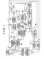
- FIG 1 is a block diagram for describing the electrical configuration of an electric power steering system (an example of a vehicle steering system) to which a motor control unit according to a first embodiment of the invention is applied.
- the electric power steering system includes a torque sensor 1, a motor 3 (brushless motor), a steering angle sensor 4, a motor control unit 5, and a vehicle speed sensor 6.
- the torque sensor 1 detects the steering torque T that is applied to a steering wheel 10 that serves as an operation member used to steer a vehicle.
- the motor 3 (brushless motor) applies a steering assist force to a steering mechanism 2 of the vehicle via a speed reduction mechanism 7.
- the steering angle sensor 4 detects the steering angle that is the rotational angle of the steering wheel 10.
- the motor control unit 5 controls driving of the motor 3.
- the vehicle speed sensor 6 detects the speed of the vehicle in which the electric power steering system is mounted.
- the steering angle sensor 4 detects the amount of rotation (rotational angle) of the steering wheel 10 from the neutral position (reference position) of the steering wheel 10 in the clockwise direction, and the amount of rotation of the steering wheel 10 from the neutral position in the counterclockwise direction.
- the steering angle sensor 4 outputs, as a positive value, the amount of rotation of the steering wheel 10 from the neutral position in the clockwise direction.
- the steering angle sensor 4 outputs, as a negative value, the amount of rotation of the steering wheel 10 from the neutral position in the counterclockwise direction.
- the motor control unit 5 drives the motor 3 based on the steering torque detected by the torque sensor 1, the steering angle detected by the steering angle sensor 4, and the vehicle speed detected by the vehicle speed sensor 6, thereby providing appropriate steering assistance based on the steering state and the vehicle speed.
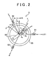
- the motor 3 is a three-phase brushless motor. As illustrated in FIG 2 , the motor 3 includes a rotor 50 that serves as a field magnet, and a U-phase stator coil 51, a V-phase stator coil 52, and a W-phase stator coil 53 that are arranged on a stator 55 that faces the rotor 50.
- the motor 3 may be an inner rotor motor in which a stator is arranged on the outer side of a rotor so as to face the rotor, or an outer rotor motor in which a stator is arranged on the inner side of a tubular rotor so as to face the rotor.
- a three-phase fixed coordinate system (UVW coordinate system), where the direction in which the U-phase stator coil 51 extends, the direction in which the V-phase coil 52 extends, and the direction in which the W-phase coil 53 extends are used as the U-axis, the V-axis and W-axis, respectively, is defied.
- a two-phase rotating coordinate system (dq coordinate system: actual rotating coordinate system), where the direction of the magnetic poles of the rotor 50 is used as the d-axis (axis of the magnetic poles) and the direction that is perpendicular to the d-axis within the rotary plane of the rotor 50 is used as the q-axis (torque axis), is defined.
- the dq coordinate system is a rotating coordinate system that rotates together with the rotor 50.
- the d-axis current may be set to 0 and the q-axis current may be controlled based on a desired torque.
- the rotational angle (rotor angle) ⁇ M of the rotor 50 is a rotational angle of the d-axis with respect to the U-axis.
- the dq coordinate system is an actual rotating coordinate system that rotates in accordance with the rotor angle ⁇ M . With the use of the rotor angle ⁇ M , coordinate conversion may be made between the UVW coordinate system and the dq coordinate system.
- the control angle ⁇ C that indicates the rotational angle used in the control is employed.
- the control angle ⁇ C is an imaginary rotational angle with respect to the U-axis.
- An imaginary two-phase rotating coordinate system ( ⁇ coordinate system: hereafter, referred to as "imaginary rotating coordinate system"), where the imaginary axis that forms the control angle ⁇ C with the U-axis is used as the ⁇ -axis, and the axis that is advanced 90 degrees from the ⁇ -axis is used as the ⁇ -axis, is defined.
- the control angle ⁇ C is equal to the rotor angle ⁇ M
- the ⁇ coordinate system which is the imaginary rotating coordinate system
- the dq coordinate system which is the actual rotating coordinate system
- the ⁇ -axis which is the imaginary axis
- the ⁇ -axis which is the imaginary axis
- the ⁇ -axis which is the imaginary axis
- the ⁇ -axis which is the imaginary axis
- the q-axis which is the actual axis.
- the ⁇ coordinate system is an imaginary rotating coordinate system that rotates in accordance with the control angle ⁇ C . Coordinate conversion may be made between the UVW coordinate system and the ⁇ coordinate system with the use of the control angle ⁇ c.
- the ⁇ -axis current I ⁇ When the ⁇ -axis current I ⁇ is supplied to the motor 3 based on the control angle ⁇ C , the q-axis component of the ⁇ -axis current I ⁇ (orthogonal projection to the q-axis) is used as the q-axis current I q that contributes to generation of torque by the rotor 50. That is, the relationship expressed by Equation 1 is established between the ⁇ -axis current I ⁇ and the q-axis current I q .
- I q I ⁇ ⁇ sin ⁇ L
- the motor control unit 5 includes a microcomputer 11, a drive circuit (inverter circuit) 12 that is controlled by the microcomputer 11 and that supplies electric power to the motor 3, and a current detection unit 13 that detects an electric current that flows through the stator coil of each phase of the motor 3.
- the current detection unit 13 detects the U-phase current I U , the V-phase current I V and the W-phase current I W that flow through the U-phase stator coil 51, the V-phase stator coil 52, and the W-phase stator coil 53 of the motor 3, respectively, (these phase currents will be collectively referred to as "three-phase detected current I UVW " where appropriate).
- the U-phase current I U , the V-phase current I v and the W-phase current I W are the current values in the directions of the axes of the UVW coordinate system.
- the microcomputer 11 includes a CPU and memories (a ROM, a RAM, etc.), and serves as multiple function, processing units by executing predetermined programs.
- the multiple function processing units include a steering torque limiter 20, a command steering torque setting unit 21, a torque deviation calculation unit 22, a PI (proportional-integral) control unit 23, an addition angle limiter 24, a control angle calculation unit 26, a command current value preparation unit 30, current deviation calculation unit 32, a PI control unit 33, a ⁇ /UVW conversion unit 34, a PWM (Pulse Width Modulation) control unit 35, and a UVW/ ⁇ conversion unit 36.
- a steering torque limiter 20 a command steering torque setting unit 21, a torque deviation calculation unit 22, a PI (proportional-integral) control unit 23, an addition angle limiter 24, a control angle calculation unit 26, a command current value preparation unit 30, current deviation calculation unit 32, a PI control unit 33, a ⁇ /UVW conversion unit 34, a PWM (Pulse Width Modulation) control unit 35, and a UVW/ ⁇ conversion unit 36.
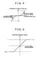
- the command steering torque setting unit 21 sets the command steering torque T* based on the steering angle detected by the steering angle sensor 4 and the vehicle speed detected by the vehicle speed sensor 6. For example, as shown in FIG 4 , the command steering torque T* when the steering angle is a positive value (when the steering wheel 10 is operated clockwise) is set to a positive value (torque applied in the clockwise direction), whereas the command steering torque T* when the steering angle is a negative value (when the steering wheel 10 is operated counterclockwise) is set to a negative value (torque applied in the counterclockwise direction).
- the command steering torque T* is set in such a manner that the absolute value of the command steering torque T* increases (non-linearly increases, in the example in FIG.
- the command steering torque T* is set to a value within a range between a predetermined upper limit (positive value (e.g. +6Nm)) and a predetermined lower limit (negative value (e.g. -6Nm)).
- the command steering torque T* is set in such a manner that the absolute value of the command steering torque T* decreases as the vehicle speed increases. That is, a vehicle speed-sensitive control is executed.
- the steering torque limiter 20 When the detected steering torque T from the torque sensor 1 is equal to or higher than the upper saturation value +T max , the steering torque limiter 20 outputs the upper saturation value +T max . When the detected steering torque T from the torque sensor 1 is equal to or lower than the lower saturation value -T max , the steering torque limited 20 outputs the lower saturation value -T max .
- the saturation values +T max and -T max define a stable range (reliable range) of the output signal from the torque sensor 1. That is, in the range where the output from the torque sensor 1 is higher than the upper saturation value +T max and the range where the output from the torque sensor 1 is lower than the lower saturation value -T max . the output signal from the torque sensor 1 is unstable and does not correspond to the actual steering torque. In other words, the saturation values +T max and -T max are determined based on the output characteristic of the torque sensor 1.
- the torque deviation calculation unit 22 calculates the deviation (torque deviation) ⁇ T (T - T*) of the steering torque T that is detected by the torque sensor 1 and then subjected to the limitation process by the steering torque limiter 20 (hereinafter, will be referred to as "detected steering torque T") from the command steering torque T* set by the command steering torque setting unit 21,
- the PI control unit 23 executes the PI calculation on the torque deviation ⁇ T. That is, the torque deviation calculation unit 22 and the PI control unit 23 constitute a torque feedback control unit that brings the detected steering torque T to the command steering torque T*,
- the PI control unit 23 calculates the addition angle ⁇ for the control angle ⁇ c by executing the PI calculation on the torque deviation ⁇ T. Therefore, the torque feedback control unit constitutes an addition angle calculation unit that calculates the addition angle ⁇ .
- the addition angle limiter 24 imposes limitations on the addition angle ⁇ obtained by the PI control unit 23. More specifically, the addition angle limiter 24 limits the addition angle ⁇ to a value within a range between a predetermined upper limit UL (positive value) and a predetermined lower limit LL (negative value).
- the preset value of the predetermined limit ⁇ max is determined based on, for example, the maximum steering angular speed.
- the maximum steering angular speed is the maximum assumable value of the steering angular speed of the steering wheel 10, and, for example, approximately 800 deg/sec.
- the rate of change in the electrical angle of the rotor 50 (angular speed in the electrical angle: maximum rotor angular speed) at the maximum steering angular speed is expressed by the product of the maximum steering angular speed, the speed reduction ratio of the speed reduction mechanism 7, and the number of pole pairs of the rotor 50, as indicated by Equation 2.
- the number of pole pairs is the number of magnetic pole pairs (pair of north pole and south pole) of the rotor 50.
- Maximum rotor angular speed maximum steering angular speed ⁇ speed reduction ratio ⁇ number of pole pairs
- the maximum value of the amount of change in the electrical angle of the rotor 50 between the calculations (in the calculation cycle) of the control angle ⁇ C is expressed by the value obtained by multiplying the maximum rotor angular speed by the calculation cycle, as indicated by Equation 3.
- This maximum value of the amount of change in the rotor angle is the maximum amount of change in the control angle ⁇ C that is permitted within one calculation cycle. Therefore, the maximum value of the amount of change in the rotor angle may be used as the preset value of the limit ⁇ max .
- the limit ⁇ max the upper limit UL and the lower limit LL for the addition angle ⁇ are expressed by Equation 4 and Equation 5, respectively.
- the addition angle ⁇ obtained through the limitation process executed by the addition angle limiter 24 is added to the immediately preceding value ⁇ C (n-1) (n is the number of the present calculation cycle) of the control angle ⁇ C by an addition unit 26A of the control angle calculation unit 26 ("Z -1 " indicates the immediately preceding value indicated by a signal).
- the initial value of the control angle ⁇ c is a prescribed value (e.g. 0).
- the control angle calculation unit 26 includes the addition unit 26A that adds the addition angle ⁇ provided from the addition angle limiter 24 to the immediately preceding value ⁇ C (n-1) of the control angle ⁇ C . That is, the control angle calculation unit 26 calculates the control angle ⁇ c in predetermined calculation cycles. The control angle calculation unit 26 uses the control angle ⁇ C in the immediately preceding calculation cycle as the immediately preceding value ⁇ C (n-1), and obtains the present value ⁇ C (n) that is the control angle ⁇ C in the present calculation cycle based on the immediately preceding value ⁇ C (n-1).
- the command current value preparation unit 30 prepares, as command current values, values of electric currents that should be supplied to the coordinate axes (imaginary axes) of the ⁇ coordinate system, which is the imaginary rotating coordinate system that corresponds to the control angle ⁇ C that is a rotational angle used in the control. More specifically, the command current value preparation unit 30 prepares the ⁇ -axis command current value I ⁇ * and the ⁇ -axis command current value I ⁇ * (hereinafter, these values will be collectively referred to as "two-phase command current value I ⁇ *" where appropriate). The command current value preparation unit 30 sets the ⁇ -axis command current value I ⁇ * to a significant value, and sets the ⁇ -axis command current value I ⁇ * to 0.
- the command current value preparation unit 30 sets the ⁇ -axis command current value I ⁇ * based on the command steering torque T* that is set by the command steering torque setting unit 21 and the detected steering torque T that is detected by the torque sensor 1. That is, the command current value preparation unit 30 is a command current setting unit that sets the two-phase command current value I ⁇ *.
- the command current value preparation unit 30 includes a command current increase/decrease amount calculation unit 30A, an addition unit 30B and an upper/lower limiter 30C.
- the current increase/decrease amount ⁇ I ⁇ * is set to 0 in order to maintain the present command current value I ⁇ *.
- the command current value I ⁇ * is set to a value higher than 0 in order to fill up a deficiency in the assist torque.
- the command current value I ⁇ * is increased.
- the command current value I ⁇ * is set to a value lower than 0 in order to suppress power consumption and generation of heat in the motor.
- the command current value I ⁇ * is decreased.
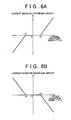
- FIG 6A shows an example a manner of setting the current increase/decrease amount ⁇ I ⁇ * with respect to the torque deviation ⁇ T when sign of the command steering torque T* is the positive sign (T* ⁇ 0).
- the torque deviation ⁇ T is a value within a range equal to or larger than the predetermined value -A (A > 0) and equal to or smaller than the predetermined value +A
- the current increase/decrease amount ⁇ I ⁇ * is set to 0.
- the current increase/decrease amount ⁇ I ⁇ * is set such that as the torque deviation ⁇ T decreases from the predetermined value -A, the current increase/decrease amount ⁇ I ⁇ * decreases (linearly decreases in the example in FIG. 6A ) from 0.
- the current increase/decrease amount ⁇ I ⁇ * is set such that as the torque deviation ⁇ T increases from the predetermined value +A, the current increase/decrease amount ⁇ I ⁇ * increases (linearly increases in the example in FIG 6A ) from 0.
- the absolute value of the detected steering torque T is larger than the absolute value of the command steering torque T*. Accordingly, in this case, it is considered that the motor torque (assist torque) is insufficient. Therefore, when the torque deviation ⁇ T is larger than the predetermined value +A, the current increase/decrease amount ⁇ I ⁇ * is set to a positive value in order to fill up a deficiency in the assist torque. In this case, as the absolute value of the torque deviation ⁇ T increases, the absolute value of the current increase/decrease amount ⁇ I ⁇ * also increases (becomes a positive value that has a larger absolute value).
- the absolute value of the detected steering torque T is smaller than the absolute value of the command steering torque T*. Accordingly, in this case, it is considered that the motor torque (assist torque) is not insufficient. Therefore, when the torque deviation AT is smaller than the predetermined value -A, the current increase/decrease amount ⁇ I ⁇ * is set to a negative value in order to suppress power consumption and generation of heat in the motor 3.
- the absolute value of the current increase/decrease amount ⁇ I ⁇ * also increases (becomes a negative value that has a larger absolute value).
- FIG. 6B shows an example a manner of setting the current increase/decrease amount ⁇ I ⁇ * with respect to the torque deviation ⁇ T when the sign of the command steering torque T* is the negative sign (T* ⁇ 0).
- the torque deviation ⁇ T is a value within the range equal to or larger than the predetermined value -A and equal to or smaller than the predetermined value +A
- the current increase/decrease amount ⁇ I ⁇ * is set to 0.
- the current increase/decrease amount ⁇ I ⁇ * is set such that as the torque deviation ⁇ T decreases from the predetermined value -A, the current increase/decrease amount ⁇ I ⁇ * increases (linearly increases in the example in FIG 6B ) from 0.
- the current increase/decrease amount ⁇ I ⁇ * is set such that as the torque deviation ⁇ T increases from the predetermined value +A, the current increase/decrease amount ⁇ I ⁇ * decreases (linearly decreases in the example in FIG. 6B ) from 0.
- the absolute value of the detected steering torque T is smaller than the absolute value of the command steering torque T*. Accordingly, in this case, it is considered that the assist torque is not insufficient. Therefore, when the torque deviation ⁇ T is larger than the predetermined value +A, the current increase/decrease amount ⁇ I ⁇ * is set to a negative value in order to suppress power consumption and generation of heat in the motor 3. In this case, as the absolute value of the torque deviation ⁇ T increases, the absolute value of the current increase/decrease amount ⁇ I ⁇ * also increases (becomes a negative value that has a larger absolute value).
- the absolute value of the detected steering torque T is larger than the absolute value of the command steering torque T*. Accordingly, in this case, it is considered that the assist torque is insufficient. Therefore, when the torque deviation ⁇ T is smaller than the predetermined value -A, the current increase/decrease amount ⁇ I ⁇ * is set to a positive value in order to fill up a deficiency in the assist torque.
- the absolute value of the current increase/decrease amount ⁇ I ⁇ * also increases (becomes a positive value that has a larger absolute value).
- the current increase/decrease amount ⁇ I ⁇ * calculated by the command current increase/decrease amount calculation unit 30A is added to the immediately preceding value I ⁇ *(n-1) ("n" is the number of the present calculation cycle) of the command current value I ⁇ * by the addition unit 30B ("Z -1 " indicates the immediately preceding value indicated by a signal).
- the command current value I ⁇ * in the present calculation cycle is calculated.
- the initial value of the command current value I ⁇ * is a prescribed value (e.g. 0).
- the command current value I ⁇ * obtained by the addition unit 30B is provided to the upper/lower limiter 30C.
- the upper/lower limiter 30C limits the command current value I ⁇ * obtained by the addition unit 30B to a value within a range from the predetermined lower limit ⁇ min ( ⁇ min ⁇ 0) to the predetermined upper limit ⁇ max ( ⁇ max > ⁇ min ).
- the upper/lower limiter 30C outputs the command current value I ⁇ * without correction.
- the upper/lower limiter 30C outputs the lower limit ⁇ min as the command current value I ⁇ * in the present calculation cycle.
- the upper/lower limiter 30C outputs the upper limit ⁇ max as the command current value I ⁇ * in the present calculation cycle.
- the ⁇ -axis detected current I ⁇ and the ⁇ -axis detected current I ⁇ are provided from the UVW/ ⁇ conversion unit 36 to the deviation calculation unit 32.
- the UVW/ ⁇ conversion unit 36 converts the three-phase detected currents I UVW (U-phase detected current I U , V-pbase detected current Iv, and the W-phase detected current I W ) of the UVW coordinate system, which is detected by the current detection unit 13, into the two-phase detected currents I ⁇ and I ⁇ of the ⁇ coordinate system (hereinafter, these phase currents will be collectively refereed to as "two-phase detected current I ⁇ " where appropriate). These two-phase detected currents I ⁇ and I ⁇ are provided to the current deviation calculation unit 32.
- the control angle ⁇ c calculated by the control angle calculation unit 26 is used for the coordinate conversion that is executed by the UVW/ ⁇ conversion unit 36.
- the PI control unit 33 executes the PI calculation on the current deviation calculated by the current deviation calculation unit 32 to prepare the two-phase command voltage V ⁇ * (the ⁇ -axis command voltage V y * and the ⁇ -axis command voltage V ⁇ *) that should be applied to the motor 3.
- the two-phase command voltage V ⁇ * is provided to the ⁇ /UVW conversion unit 34.
- the ⁇ /UVW conversion unit 34 executes the coordinate conversion calculation on the two-phase command voltage V ⁇ * to prepare the three-phase command voltage V UVW * .
- the control angle ⁇ c calculated by the control angle calculation unit 26 is used for this coordinate conversion.
- the three-phase command voltage V uvw * is formed of the U-phase command voltage V U *, the V-phase command voltage V V * and the W-phase command voltage V W *.
- the three-phase command voltage V UVW * is provided to the PWM control unit 35.
- the PWM control unit 35 prepares the U-phase PWM control signal, the V-phase FWM control signal and the W-pbase PWM control signal having duty ratios that correspond to the U-phase command voltage V U *, the V-phase command voltage V V * and the W-phase command voltage V W *, respectively, and provides the control signals to the drive circuit 12.
- the drive circuit 12 is formed of an inverter circuit having three phases that correspond to the U-phase, the V-phase and the W-phase.
- the power elements that constitute the inverter circuit are controlled based on the FWM control signals provided from the PWM control unit 35, and therefore the voltages that correspond to the three-phase command voltage V UVW * are applied to the U-phase stator coil 51, the V-phase stator coil 52 and the W-phase stator coil 53 of the motor 3.
- the current deviation calculation unit 32 and the PI control unit 33 constitute a current feedback control unit.
- the current feedback control unit controls the electric current that is supplied to the motor 3 in such a manner that the electric current that is supplied to the motor 3 approaches the two-phase command current value I ⁇ * that is set by the command current value preparation unit 30.
- FIG 3 is a control block diagram of the electric power steering system. Note that the function of the addition angle limiter 24 is omitted to simplify the explanation.
- the addition angle ⁇ is prepared.
- the q-axis current Iq contributes to generation of torque by the rotor 50.
- the value obtained by subtracting the assist torque T A from the load torque T L from the steering mechanism 2 is the steering torque that should be applied by the driver to the steering wheel 10.
- the control angle ⁇ C is updated with the use of the addition angle ⁇ that is obtained based on the deviation ⁇ T of the detected steering torque T from the command steering torque T* while an electric current is supplied to the ⁇ -axis that is the imaginary axis used in the control.
- the load angle ⁇ L changes and therefore, the torque that corresponds to the load angle ⁇ L is generated by the motor 3. Therefore, the torque that corresponds to the command steering torque T* set based on the steering angle and the vehicle speed is generated by the motor 3. Accordingly, an appropriate steering assist force that corresponds to the steering angle and the vehicle speed is applied to the steering mechanism 2. That is, a steering assist control is executed in such a manner that the steering torque increases as the absolute value of the steering angle increases and the steering torque decreases as the vehicle speed increases.
- FIG 7 is a flowchart for describing the function of the addition angle limiter 24.
- the addition angle limiter 24 compares the addition angle ⁇ obtained by the PI control unit 23 with the upper limit UL (step (hereinafter referred to as "S") 1).
- S upper limit UL
- the upper limit UL is substituted for the addition angle ⁇ (S2).
- the addition angle limiter 24 limits the addition angle ⁇ to a value within the range between the upper limit UL and the lower limit LL so as to stabilize the control. More specifically, although the control state is unstable (assist force is unstable) when the electric current is low or when the control starts, the control is encouraged to move to the stable state.
- the current increase/decrease amount ⁇ I ⁇ * calculated by the command current increase/decrease amount calculation unit 30A of the command current value preparation unit 30 is a positive value.
- the absolute value of the torque deviation ⁇ T becomes larger, the absolute value of the current increase/decrease amount ⁇ I y * also becomes larger (becomes a positive value having a larger absolute value).
- the current increase/decrease amount ⁇ I ⁇ * is added to the immediately preceding value of the command current value I ⁇ * by the addition unit 30B. Therefore, the command current value I ⁇ * in the present calculation cycle becomes higher than that in the immediately preceding cycle. As a result, a deficiency in the assist torque is filled up, and the steering torque T is promptly brought to the command steering torque T*.
- the current increase/decrease amount ⁇ I ⁇ * calculated by the command current increase/decrease amount calculation unit 30A of the command current value preparation unit 30 is a negative value.
- the absolute value of the torque deviation ⁇ T becomes larger
- the absolute value of the current increase/decrease amount ⁇ I ⁇ also becomes larger (becomes a negative value having a larger absolute value).
- the current increase/decrease amount ⁇ I ⁇ * is added to the immediately preceding value of the command current value I ⁇ * by the addition unit 30B. Therefore, the command current value I ⁇ * in the present calculation cycle becomes lower than that in the immediately preceding cycle- Thus, the power consumption is suppressed and generation of heat in the motor 3 is suppressed.
- FIG 8 is a block diagram for describing the configuration of an electric power steering system to which a motor control unit according to a second embodiment of the invention is applied.
- the portions that correspond to those in FIG 1 are denoted by the same reference numerals as those in FIG 1 .
- a command current value preparation unit 60 is provided instead of the command current value preparation unit 30 shown in FIG. 1 .
- the command current value preparation unit 60 sets the ⁇ -axis command current value I ⁇ * to a significant value while setting the ⁇ -axis command current value I ⁇ * to 0. More specifically, the command current value preparation unit 60 sets the ⁇ -axis command current value I ⁇ * based on the command steering torque T* set by the command steering torque setting unit 21 and the torque deviation ⁇ T calculated by the torque deviation calculation unit 22.
- the command current value preparation unit 60 includes a first PI control unit 60A, a second PI control unit 60B, a switching unit 60C, an addition unit 60D, and an upper/lower limiter 60E.
- the first PI control unit 60A calculates the current increase/decrease amount ⁇ I ⁇ * for the command current value I ⁇ * by executing the PI control on the torque deviation ⁇ T on the assumption that the sign of the command steering torque T* is the positive sign.
- the first PI control unit 60A executes a feedback control on the current increase/decrease amount ⁇ I ⁇ * so that the torque deviation ⁇ T becomes 0.
- the first PI control unit 60A calculates the current increase/decrease amount ⁇ I ⁇ *, which is a positive value, so that the deviation ⁇ T approaches 0.
- the first PI control unit 60A calculates the current increase/decrease amount ⁇ I ⁇ * , which is a negative value, so that the deviation ⁇ T approaches 0.
- the absolute value of the current increase/decrease amount ⁇ I ⁇ * increases as the absolute value of the torque deviation ⁇ T increases.
- the second PI control unit 60B calculates the current increase/decrease amount ⁇ I ⁇ * for the command current value I ⁇ * by executing the PI control on the torque deviation ⁇ T on the assumption that the sign of the command steering torque T* is the negative sign.
- the second PI control unit 60B executes a feedback control on the current increase/decrease amount ⁇ I ⁇ * so that the torque deviation ⁇ T becomes 0.
- the second PI control unit 60B calculates the current increase/decrease amount ⁇ I ⁇ *, which is a negative value, so that the deviation ⁇ T approaches 0.
- the second PI control unit 60B calculates the current increase/decrease amount ⁇ I ⁇ *, which is a positive value, so that the deviation ⁇ T approaches 0.
- the absolute value of the current increase/decrease amount ⁇ I ⁇ * increases as the absolute value of the torque deviation ⁇ T increases.
- the switching unit 60C selects one of the current increase/decrease amount ⁇ I ⁇ * calculated by the first PI control unit 60A and the current increase/decrease amount ⁇ I ⁇ * calculated by the second PI control unit 60B depending on the sign of the command steering torque T*, and outputs the selected current increase/decrease amount ⁇ I ⁇ *. More specifically, when the sign of the command steering torque T* is the positive sign, the switching unit 60C selects and outputs the current increase/decrease amount ⁇ I ⁇ * calculated by the first PI control unit 60A. On the other hand, when the sign of the command steering torque T* is the negative sign, the switching unit 60C selects and outputs the current increase/decrease amount ⁇ I ⁇ * calculated by the second PI control unit 60B.
- the current increase/decrease amount ⁇ I ⁇ * output from the switching unit 60C is added to the immediately preceding value I ⁇ *(n-1) ("n" is the number of the present calculation cycle) of the command current value I ⁇ * by the addition unit 60D ("Z -1 " indicates the innmediately preceding value indicated by a signal).
- the command current value I y * in the present calculation cycle is calculated.
- the initial value of the command current value I ⁇ * is a prescribed value (e.g. 0).
- the command current value I ⁇ * obtained by the addition unit 60D is provided to the upper/lower limiter 60E.
- the upper/lower limiter 60E limits the command current value I ⁇ * obtained by the addition unit 60D to a value within a range from the predetermined lower limit ⁇ min ( ⁇ min ⁇ 0) to the predetermined upper limit ⁇ max ( ⁇ max > ⁇ min ).
- the upper/lower limiter 60E outputs the command current value I ⁇ * without correction.
- the upper/lower limiter 60E outputs the lower limit min as the command current value I ⁇ * in the present calculation cycle.
- the upper/lower limiter 60E outputs the upper limit ⁇ max as the command current value I ⁇ * in the present calculation cycle.
- FIG 9 is a block diagram for describing the configuration of an electric power steering system to which a motor control unit according to a third embodiment of the invention is applied.
- the portions that correspond to those in FIG 1 are denoted by the same reference numerals as those in FIG 1 .
- a command current value preparation unit 70 is provided instead of the command current value preparation unit 30 shown in FIG 1 .
- the command current value preparation unit 70 sets the ⁇ -axis command current value I ⁇ * to a significant value, and sets the ⁇ -axis command current value I ⁇ * to 0.
- the command current value preparation unit 70 sets the ⁇ -axis command current value I ⁇ * based on the steering torque (detected steering torque T) that is detected by the torque sensor 1 and then subjected to the limitation process by the steering torque limiter 20 and the addition angle ⁇ calculated by the PI control unit 23 and then subjected to the limitation process by the addition angle limited 24.
- the command current value preparation unit 70 sets the ⁇ -axis command current value I ⁇ * based on the ratio between the change amount ⁇ T of the detected steering torque T (hereinafter, referred to as "steering torque change amount ⁇ T") and the addition angle ⁇ .
- the steering torque change amount ⁇ T is obtained by subtracting the detected steering torque T(n-1) in the immediately preceding calculation cycle from the detected steering torque T(n) in the present calculation cycle.
- the command current value preparation unit 70 includes a command current increase/decrease amount calculation unit 70A, an addition unit 70B and an upper/lower limiter 70C.
- the command current increase/decrease amount calculation unit 70A calculates the current increase/decrease amount ⁇ I ⁇ * for the command current value I ⁇ * based on the absolute value of the ratio of the steering torque change amount ⁇ T to the addition angle ⁇ (
- the ratio of the steering torque change amount ⁇ T to the addition angle ⁇ ( ⁇ T/ ⁇ ) is obtained by dividing the steering torque change amount ⁇ T calculated in the present calculation cycle by the addition angle ⁇ calculated by the PI control unit 23 and then subjected to the limitation process by the addition angle limiter 24 in the immediately preceding calculation cycle or the present calculation cycle.
- the ratio of the addition angle ⁇ to the steering torque change amount ⁇ T ( ⁇ / ⁇ T) is obtained by dividing the addition angle ⁇ calculated by the PI control unit 23 and then subjected to the limitation process by the addition angle limiter 24 in the immediately preceding calculation cycle or the present calculation cycle by the steering torque change amount ⁇ T calculated in the present calculation cycle.
- the command current increase/decrease amount calculation unit 70A calculates the current increase/decrease amount ⁇ I ⁇ * for the command current value I ⁇ * in the following manner.
- ) and the current increase/decrease amount ⁇ I ⁇ * is set in advance.
- ) and the current increase/decrease amount ⁇ I ⁇ * is set in advance.
- the relationship between the present command current value I ⁇ * and the increase/decrease amount gain G is set in advance.
- the command current increase/decrease amount calculation unit 70A calculates the base value of the current increase/decrease amount ⁇ I ⁇ * based on the absolute value of the other ratio (
- the command current increase/decrease amount calculation unit 70A calculates the base value of the current increase/decrease amount ⁇ I ⁇ *based on the absolute value of the other ratio (
- FIG. 10A shows an example of a manner of setting the current increase/decrease amount ⁇ I ⁇ * with respect to the absolute value of the ratio of the steering torque change amount ⁇ T to the addition angle ⁇ (
- ) is within a range equal to or larger than the predetermined value B (B>0) and equal to or smaller than the predetermined value C (C > B)
- the current increase/decrease amount ⁇ I ⁇ * is set to 0.
- the current increase/decrease amount ⁇ I ⁇ * is set such that as the absolute value (
- the current increase/decrease amount ⁇ I ⁇ * is set such that as the absolute value (
- the reason why the current increase/decrease amount ⁇ I ⁇ * is set in the manner shown in FIG 10A will be described below.
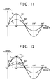
- FIG 11 shows the relationship between the load angle ⁇ L and the assist torque T A .
- the assist torque T A is a value obtained by multiplying the q-axis current I q by the torque constant K T of the motor 3. Therefore, a change in the assist torque T A with respect to the load angle ⁇ L is expressed by a curve (sine curve) shown in FIG 11 .
- the curve S1 shows the characteristic when the ⁇ -axis current I ⁇ is a relatively high value
- the curve S2 shows the characteristic when the ⁇ -axis current I ⁇ is a relatively low value.
- the PI control unit 23 operates such that the load angle ⁇ L is controlled within a range where the load angle ⁇ L is equal to or larger than 0° and equal to or smaller than 90° and a range where the load angle ⁇ L is equal to or larger than 270° and equal to or smaller than 360° (hereinafter, referred to as "range where the load angle ⁇ L is equal to or larger than -90° and equal to or smaller than 90°"). In these ranges, the assist torque monotonously increases.
- the PI control unit 23 may operate such that the load angle ⁇ L is controlled within a range where the load angle ⁇ L is equal to or larger than 90° and equal to or smaller than 270°. In this range, the assist torque monotonously decreases.
- the load angle ⁇ L is near 0°.
- the assist torque characteristic is expressed by the curve S1 in FIG. 11
- the inclination (corresponding to the ratio ⁇ T/ ⁇ ) of the curve S1 at the point a at which the load angle ⁇ L is near 0° is higher than the inclination of the curve S1 at the point b near 90°.
- the efficiency of the assist torque T A with respect to the ⁇ -axis current I ⁇ is low.
- the efficiency of the assist torque T A with respect to the ⁇ -axis current I ⁇ is high. This is because when the load angle ⁇ L is near 90°, the magnetic field of the coil can be generated in the direction substantially perpendicular to the rotor 50. If the ⁇ -axis current I ⁇ is decreased when the load angle ⁇ L is near 0°, control is executed such that the load angle ⁇ L becomes a value near 90° in order to generate the same magnitude of assist torque.
- the current increase/decrease amount ⁇ I ⁇ * is set such that as the absolute value of the ratio of the steering torque change amount ⁇ T to the addition angle ⁇ (
- ) is small, the amount of change in the assist torque T A with respect to the amount of change in the load angle ⁇ L is small. Therefore, it is considered that the load angle ⁇ L is near 90° (or -90°).
- the assist torque When the load angle ⁇ L is near 90°, the assist torque has reached the substantially maximum value at the present ⁇ -axis current I ⁇ , and there is a possibility that the detected steering torque T cannot be brought to the command steering torque T* due to shortage of the assist torque. Therefore, in this case, preferably, the ⁇ -axis current I ⁇ is increased to increase the assist torque.
- the current increase/decrease amount ⁇ I ⁇ * is set such that as the absolute value of the ratio of the steering torque change amount ⁇ T to the addition angle ⁇ (
- FIG. 10B shows an example of a manner of setting the current increase/decrease amount ⁇ I ⁇ * with respect to the absolute value of the ratio of the addition angle ⁇ to the steering torque change amount ⁇ T (
- the current increase/decrease amount ⁇ I ⁇ * is set to 0.
- the current increase/decrease amount ⁇ I ⁇ * is set such that as the absolute value
- the current increase/decrease amount ⁇ I ⁇ * is set such that as the absolute value
- FIG 10C shows an example of a manner of setting the increase/decrease amount gain G with respect to the command current value I ⁇ *. In the example in FIG.
- the increase/decrease amount gain G is set so as to monotonously decrease as the present command current value I ⁇ * (immediately preceding value of the command current value I ⁇ *) becomes higher. More specifically, when the present command current value I ⁇ * is 0, the increase/decrease amount gain G is set to 1. When the present command current value ⁇ I ⁇ * is within a range equal to or higher than 0, the increase/decrease amount gain G is set so as to monotonously decrease (linearly decrease in the example in FIG 10C ) from 1. The reason why the increase/decrease amount gain G is set in the manner shown in FIG 10 will be described below.
- FIG 12 shows the relationship between the load angle ⁇ L and the assist torque T A -
- the curve S1 shows the characteristic when the ⁇ -axis current I ⁇ is a relatively high value
- the curve S2 shows the characteristic when the ⁇ -axis current I ⁇ is a relatively low value.
- the assist torque characteristic is indicated by the curve S2 in the case where the ⁇ -axis current I ⁇ is a low value and the load angle ⁇ L is an angle near 0°, which corresponds to the point d on the curve S2, the absolute value
- is large.
- the ⁇ -axis current I ⁇ is decreased to increase the efficiency of the assist torque T A with respect to the ⁇ -axis current I ⁇ .
- the load angle ⁇ L is shifted to an angle near 0°.
- the point on the characteristic curve S1, at which the characteristic curve S1 has the same inclination as that of the characteristic curve S2 at the point d on the curve S2 is e. That is, if the absolute value
- the amount of decrease in the ⁇ -axis current I ⁇ is relatively small, as indicated by the arrow Y1 in FIG. 12 . Therefore, when the command current value I ⁇ * is decreased to decrease the ⁇ -axis current I ⁇ , preferably, the amount of decrease is made smaller as the present command current value I ⁇ * is larger.
- the base value of the current increase/decrease amount ⁇ I ⁇ * is a positive value
- is small (when the absolute value
- the ⁇ -axis current I ⁇ is increased in order to increase the assist torque.
- the increase amount is made smaller as the present command current value I ⁇ * is larger.
- the increase/decrease amount gain G is made smaller as the present command current value I ⁇ * is higher.
- the final current increase/decrease amount ⁇ I ⁇ * is obtained by multiplying the base value of the current increase/decrease amount ⁇ I ⁇ * calculated based on the characteristic shown in FIG. 10A or FIG. 10B by the increase/decrease amount gain G obtained based on the characteristic shown in FIG. 10C .
- the current increase/decrease amount ⁇ I ⁇ * calculated by the command current increase/decrease amount calculation unit 70A is added to the immediately preceding value I ⁇ *(n-1) (n is the number of the present calculation cycle) of the command current value I ⁇ * by the addition unit 70B ("Z -1 " indicates the immediately preceding value indicated by a signal).
- the command current value I ⁇ * in the present calculation cycle is calculated.
- the initial value of the command current value I ⁇ * is a prescribed value (e.g. 0).
- the command current value I ⁇ * obtained by the addition unit 70B is provided to the upper/lower limiter 70C.
- the upper/lower limiter 70C limits the command current value I ⁇ * obtained by the addition unit 70B to a value within a range from the predetermined lower limit ⁇ min ( ⁇ min ⁇ 0) and the predetermined upper limit ⁇ max ( ⁇ max > ⁇ min ).
- the upper/lower limiter 70C outputs the command current value I ⁇ * without correction.
- the upper/lower limiter 70C outputs the lower limit ⁇ min as the command current value I ⁇ * in the present calculation cycle.
- the upper/lower limiter 70C outputs the upper limit ⁇ max as the command current value I ⁇ * in the present calculation cycle.
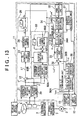
- FIG 13 is a block diagram for describing the configuration of an electric power steering system to which a motor control unit according to a fourth embodiment of the invention is applied.
- the microcomputer 11 further includes an induced voltage estimation unit 37 that serves as a function processing unit.
- a command current value preparation unit 80 is provided instead of the command current value preparation unit 30 shown in FIG. 1 .
- the command current value preparation unit 80 sets the ⁇ -axis command current value I ⁇ * to a significant value, and sets the ⁇ -axis command current value I ⁇ * to 0.
- the command current value preparation unit 80 sets the ⁇ -axis command current value I ⁇ * based on the command steering torque T* that is set by the command steering torque setting unit 21, the detected steering torque T that is detected by the torque sensor 1, and the estimated induced voltage E ⁇ ⁇ estimated by the induced voltage estimation unit 37.
- the UVW/ ⁇ conversion unit 36 is formed of a UVW/ ⁇ conversion unit 36A and an ⁇ / ⁇ conversion unit 36B.
- the UVW/ ⁇ conversion unit 36A converts the three-phase detected current I UVM (U-phase detected current I U , V-phase detected current Iv and W-pbase detected current I w ) of the UVW coordinate system, which is detected by the current detection unit 13, into the two-phase detected current I ⁇ , and I ⁇ (hereinafter, collectively referred to as "two-phase detected current I ⁇ " where appropriate) of the ⁇ coordinate system that is the two-phase fixed coordinate system.
- the ⁇ coordinate system is a fixed coordinate system where the ⁇ -axis and the ⁇ -axis (which coincides with the U-axis in the example in FIG. 2 ) that is perpendicular to the ⁇ -axis are defined within the rotary plane of the rotor 50 using the rotation center of the rotor 50 as the original point.
- the ⁇ / ⁇ conversion unit 36B converts the two-phase detected current I ⁇ into the two-pbase detected currents I ⁇ and I ⁇ (hereinafter, correctively referred to as "two-phase detected current I ⁇ " where appropriate) of the ⁇ coordinate system.
- the two-plaase detected currents I ⁇ and I ⁇ are provided to the current deviation calculation unit 32.
- the control angle ⁇ c calculated by the control angle calculation unit 26 is used for the coordinate conversion executed by the ⁇ / ⁇ conversion unit 36B.
- the ⁇ /UVW conversion unit 34 is formed of a ⁇ / ⁇ conversion unit 34A and an ⁇ /UVW conversion unit 34B.
- the ⁇ / ⁇ conversion unit 34A converts the two-phase command voltage V ⁇ * output from the PI control unit 33 into the two-phase command voltage V ⁇ * of the ⁇ coordinate system.
- the control angle ⁇ c calculated by the control angle calculation unit 26 is used for this coordinate conversion.
- the two-phase command voltage V ⁇ * is formed of the ⁇ -axis command voltage V ⁇ * and the ⁇ -axis command voltage V ⁇ *.
- the ⁇ /UVW conversion unit 34B executes coordinate conversion calculation on the two-phase command voltage V ⁇ * thereby preparing the three-phase command voltage V UVM *.
- the three-phase command voltage V UVM * is formed of the U-phase command voltage V U *, the V-phase command voltage V v * and the W-phase command voltage V w *.
- the three-phase command voltage U UVM * is provided to the PWM control unit 35
- the induced voltage estimation unit 37 estimates the inducted voltage generated by the rotation of the motor 3.
- FIG. 14 is a block diagram for describing the configuration of the induced voltage estimation unit 37.
- the induced voltage estimation unit 37 estimates the induced voltage of the motor 3 based on the two-phase detected current I ⁇ and the two-phase command voltage V ⁇ *. More specifically, the induced voltage estimation unit 37 is formed as a disturbance observer that estimates the induced voltage of the motor 3 as a disturbance based on a motor model that is a mathematical model of the motor 3.
- the motor model may be expressed by, for example, (R + pL) -1 . Note that R is an armature coil resistance, L is an ⁇ -axis inductance, and p is a differential operator. It is considered that the two-phase command voltage V ⁇ * and the induced voltage E ⁇ ( ⁇ -axis induced voltage E ⁇ and the ⁇ -axis induced voltage E B ) are applied to the motor 3.
- the induced voltage estimation unit 37 is formed of an inverse motor model (inverse model of the motor model) 65 that estimates the motor voltage using the two-phase detected current I ⁇ as an input, and a voltage deviation calculation unit 66 that obtains the deviation of the motor voltage that is estimated by the inverse motor model 65 from the two-phase command voltage V ⁇ *.
- the voltage deviation calculation unit 66 obtains the disturbance to the two-phase command voltage V ⁇ *-
- the disturbance is the estimated value E ⁇ ⁇ ( ⁇ -axis induced voltage estimated value E ⁇ ⁇ and the ⁇ -axis induced voltage estimated value E ⁇ ⁇ (hereinafter, collectively referred to as "estimated induced voltage E ⁇ ⁇ ”)) corresponding to the induced voltage E ⁇ .
- the inverse motor model 65 is expressed by, for example, R + pL.
- the command current value preparation unit 80 includes a command current increase/decrease amount calculation unit 80A, an output control unit 80B, an addition unit 80C, and an upper/lower limiter 80D.
- the command current increase/decrease amount calculation unit 80A calculates the current increase/decrease amount ⁇ I ⁇ * ( ⁇ I ⁇ * > 0) with which the command current value I ⁇ * is increased (hereinafter, referred to as "current increase mount" where appropriate).
- the command current value I ⁇ * is set to a value lower than 0 in order to suppress power consumption and generation of heat in the motor 3. That is, the command current increase/decrease amount calculation unit 80A calculates the current increase/decrease amount ⁇ I ⁇ * ( ⁇ I ⁇ * ⁇ 0) with which the command current value I ⁇ * is decreased (hereinafter, referred to as "current decrease amount" where appropriate). The details of the command current increase/decrease amount calculation unit 80A will be described later.
- the output control unit 80B outputs this current increase/decrease amount ⁇ I ⁇ *.
- the output control unit 80B outputs this current increase/decrease amount ⁇ I ⁇ * only when it is determined that a time equal to or longer than the predetermined time Ts has elapsed since the command current value I ⁇ * is decreased last time and the motor 3 (rotor 50) is at a standstill (not rotating).
- the output control unit 80B does not output the current increase/decrease amount ⁇ I ⁇ * when a time equal to or longer than the predetermined time Ts has not elapsed since the command current value I ⁇ * is decreased last time or the motor 3 is rotating.
- the predetermined time Ts is a minimum cycle when the command current value I ⁇ * is successively decreased.
- the output control unit 80B determines that the motor 3 is at a standstill.
- the output control unit 80B determines that the motor 3 is rotating.
- the threshold H is set to a value that is larger than an estimated error of the square sum (E ⁇ ⁇ 2 + E ⁇ ⁇ 2 ).
- the predetermined time Ts is set as follows. If the command current value I ⁇ * is decreased, the load angle ⁇ L is controlled such that the same magnitude of assist torque (motor torque) is generated.
- the predetermined time Ts is set to the maximum value of the time that is required to bring the load angle ⁇ L to the angle at which the same magnitude of assist torque is generated, from when the command current value I ⁇ * is decreased.
- the maximum value Ts is set to, for example the maximum value of the permissible time during which continuation of inappropriate assist torque is permitted (hereinafter, referred to as "maximum permissible time for inappropriate state").
- the “maximum permissible time for inappropriate state” is set to, for example, 100 ms.
- the command current value I ⁇ * After the command current value I ⁇ * is decreased, if the command current value I ⁇ * is further decreased before the load angle ⁇ L is brought to the angle at which the same magnitude of assist torque is generated, there is a possibility that the load angle ⁇ L is not brought to an appropriate value. Therefore, in this embodiment if the time equal to or longer than the predetermined time Ts has not elapsed since the command current value I ⁇ * is decreased last time, the current increase/decrease amount ⁇ I ⁇ * with which the command current value I ⁇ * is decreased is not output.
- the command current value I ⁇ * may be excessively decreased because the absolute value of the detected steering torque T decreases. Then, there arises a possibility that the required assist torque is not obtained. In order to avoid occurrence of such a situation, in this embodiment, the current increase/decrease amount ⁇ I ⁇ * is not output when the motor 3 (steering wheel 10) is rotating.
- FIG. 15A shows an example of a manner of setting the current increase/decrease amount ⁇ I ⁇ * with respect to the torque deviation ⁇ T when the sign of the command steering torque T* is the positive sign (T* ⁇ 0).
- the torque deviation ⁇ T is equal to the predetermined value +E (E > 0)
- the current increase/decrease amount ⁇ I ⁇ * is set to 0.
- the predetermined value E is set to a value corresponding to the variation of the output from the torque sensor 1 (maximum value of a detected error due to the variation).
- the current increase/decrease amount ⁇ I ⁇ * is fixed to the maximum value + ⁇ I ⁇ max * that is larger than 0 ( ⁇ I ⁇ max * > 0).
- the predetermined value F is set to, for example, 2Nm.
- the current increase/decrease amount ⁇ I ⁇ * is set to increase (linearly increase in the example in FIG. 15A ) within a range from 0 to the maximum value + ⁇ I ⁇ max * as the torque deviation ⁇ T increases.
- the current increase/decrease amount ⁇ I ⁇ * is fixed to the minimum value - ⁇ I ⁇ min * that is smaller than 0 ( ⁇ I ⁇ min * > 0).
- the current increase/decrease amount ⁇ I ⁇ * is set to decrease (linearly decrease in the example in FIG 15A ) within a range from 0 to the minimum value - ⁇ I ⁇ min * as the torque deviation ⁇ T decreases.
- the absolute value ⁇ I ⁇ max * of the maximum value + ⁇ I ⁇ max * of the current increase/decrease amount ⁇ I ⁇ * is the maximum value of the "current increase amount".
- the maximum value + ⁇ I ⁇ max * is set to such a value that the command current value I ⁇ * reaches the command current upper limit (upper limit for the upper/lower limits 80D) within the "maximum permissible time for inappropriate state (100 ms in this example)" if the current increase/decrease amount ⁇ I ⁇ * is set to the maximum value + ⁇ I ⁇ max *.
- the calculation cycle of the calculation of the current increase/decrease amount ⁇ I ⁇ *, executed by the command current increase/decrease amount calculation unit 80A, is set to a value shorter than the ""maximum permissible time for inappropriate state (100 ms in this example)".
- the maximum value + ⁇ I ⁇ max * is set to such a value that the command current value I ⁇ * reaches the upper limit of the command current if the maximum value + ⁇ I ⁇ max * is calculated as the current increase/decrease amount ⁇ I ⁇ * over the time corresponding to the "maximum permissible time for inappropriate state (100 ms in this example)" starting from the state where the command current value I ⁇ * is the lower limit (lower limit for the upper/lower limiter 80D).
- the absolute value ⁇ I ⁇ min * of the minimum value - ⁇ I ⁇ min * of the current increase/decrease amount ⁇ I ⁇ * is the maximum value of the "current decrease amount".
- the absolute value ⁇ I ⁇ min * is set to such a value that the corresponding assist torque change amount is equal to or smaller than the predetermined value (e.g. 2 Nm) and the time that is required to bring the load angle ⁇ L to the angle at which the same magnitude of assist torque is generated after the command current value I ⁇ * is decreased is equal to or shorter than the "maximum permissible time for inappropriate state (100 ms in this example)".
- the absolute value of the detected steering torque T is smaller than the absolute value of the command steeling torque T*. In this case, it is considered that the assist torque is not insufficient.
- the calculated torque deviation ⁇ T may be a value within the range from the predetermined value -E to the predetermined value +E.
- the command current value I ⁇ * is decreased in order to suppress power consumption and generation of heat in the motor 3.
- the current increase/decrease amount ⁇ I ⁇ * is set to a negative value in order to suppress power consumption and generation of heat in the motor 3. More specifically, when the torque deviation ⁇ T is a value between the predetermined value +E and the predetermined value +D, the current increase/decrease amount ⁇ Iy* decreases (current decrease amount increases) as the torque deviation ⁇ T decreases.
- the current increase/decrease amount ⁇ I ⁇ * is set to the minimum value - ⁇ I ⁇ min * (the maximum value of the "current decrease amount").
- the absolute value of the detected steering torque T is larger than the absolute value of the command steering torque T*. Accordingly, in this case, it is considered that the motor torque (assist torque) is insufficient. Therefore, when the torque deviation ⁇ T is larger than the predetermined value +E, the current increase/decrease amount ⁇ I ⁇ * is set to a positive value in order to fill up a deficiency in the assist torque.
- the current increase/decrease amount ⁇ I ⁇ * increases ("current increase amount” increases) as the torque deviation ⁇ T increases.
- the current increase/decrease amount ⁇ I ⁇ * is set to the maximum value + ⁇ I ⁇ max * (the maximum value of the "current increase amount").
- FIG. 15B shows an example of a manner of setting the current increase/decrease amount ⁇ I ⁇ * with respect to the torque deviation ⁇ T when the sign of the command steering torque T* is the negative sign (T* ⁇ 0).
- the current increase/decrease amount ⁇ I ⁇ * is set to 0.
- the torque deviation ⁇ T is equal to or smaller than the predetermined value -F that is smaller than the predetermined value -E
- the current increase/decrease amount ⁇ I ⁇ * is fixed to the maximum value + ⁇ I ⁇ max * that is larger than 0 ( ⁇ I ⁇ max * > 0).
- the current increase/decrease amount ⁇ I ⁇ * is set such that the current increase/decrease amount ⁇ I ⁇ * increases (linearly increases in the example in FIG. 15B ) within the range from 0 to the maximum value + ⁇ I ⁇ max * as the torque deviation ⁇ T decreases.
- the current increase/decrease amount ⁇ I ⁇ * is fixed to the minimun value - ⁇ I ⁇ * that is smaller than 0 ( ⁇ I ⁇ * > 0).
- the current increase/decrease amount ⁇ I ⁇ * is set such that the current increase/decrease amount ⁇ I ⁇ * decreases (linearly decreases in the example in FIG. 5B) within the range from 0 to the minimum value - ⁇ I ⁇ min * as the torque deviation ⁇ T increases.
- the absolute value of the detected steering torque T is smaller than the absolute value of the command steering torque T*. Accordingly, in this case, it is considered that the assist torque is not insufficient.
- the calculated torque deviation ⁇ T may be a value within the range from the predetermined value -E to the predetermined value +E.
- the command current value I ⁇ * is decreased in order to suppress power consumption and generation of heat in the motor 3.
- the current increase/decrease amount ⁇ I ⁇ * is set to a negative value in order to suppress power consumption and generation of heat in the motor 3. More specifically, when the torque deviation ⁇ T is a value between the predetermined value -E and the predetermined value +D, the current increase/decrease amount ⁇ I ⁇ * is decreased ("current decrease amount” is increased) as the torque deviation ⁇ T increases. When the torque deviation ⁇ T is a value equal to or larger than the predetermined value -D, the current increase/decrease amount ⁇ I ⁇ * is set to the minimum value - ⁇ I ⁇ min * ("maximum value of the "current decrease amount").
- the current increase/decrease amount ⁇ I ⁇ * is set to a positive value in order to fill up a deficiency in the assist torque. More specifically, when the torque deviation ⁇ T is a value between the predetermined value -E and the predetermined value -F, the current increase/decrease amount ⁇ I ⁇ * increases (the "current increase amount” increases) as the torque deviation ⁇ T decreases. When the torque deviation ⁇ T is a value equal to or smaller than the predetermined value -F, the current increase/decrease amount ⁇ I ⁇ * is set to the maximum value + ⁇ I ⁇ max * (the maximum value of the "current increase amount").
- the current increase/decrease amount May calculated by the command current increase/decrease amount calculation unit 80A is provided to the output control unit 80B.
- the output control unit 80B executes the above-described process.
- FIG 16 is a flowchart showing the operation of the command current increase/decrease amount calculation unit 80A and the output control unit 80B. The process shown in FIG 16 is executed in predetermined calculation cycles.
- the output control unit 80B determines whether the current increase/decrease amount ⁇ I ⁇ * calculated by the command current increase/decrease amount calculation unit 80A is the "current decrease amount" (S12).
- the output control unit 80B determines that the current increase/decrease amount ⁇ I ⁇ * calculated in the present calculation cycle is the "current decrease amount” if the current increase/decrease amount ⁇ I ⁇ * calculated by the command current increase/decrease amount calculation unit 80A is a negative value. On the other hand, if the current increase/decrease amount ⁇ I ⁇ * is a positive value, the output control unit 80B determines that the current increase/decrease amount ⁇ I ⁇ * calculated in the present calculation cycle is the "current increase amount".
- the output control unit 80B When it is determined that the current increase/decrease amount ⁇ I ⁇ * calculated by the command current increase/decrease amount calculation unit 80A is the "current increase amount" ("NO” in S12), the output control unit 80B outputs the current increase/decrease amount ⁇ I ⁇ * ("current increase amount") calculated in present calculation cycle (S13), and ends the process in the present calculation cycle.
- the output control unit 80B determines whether a time equal to or longer than the predetermined time Ts has elapsed since the command current value I ⁇ * is decreased last time (S14).
- the predetermined time Ts is the minimum cycle when the command current value I ⁇ * is successively decreased, and 100 ms in this example.
- a determination is made, for example, by determining whether the predetermined time Ts has elapsed since the time point at which the newest "current decrease amount" is output from the output control unit 80B.
- the current increase/decrease amount ⁇ I ⁇ * output from the output control unit 80B is added to the immediately preceding value I ⁇ *(n-1) (n is the number of the present calculation cycle) of the command current value I ⁇ * ("Z -1 " indicates the immediately preceding value indicated by a signal) by the addition unit 80C.
- the command current value I ⁇ * in the present calculation cycle is calculated.
- the initial value of the command current value I ⁇ * is a prescribed value (e.g. 0).
- the command current value I ⁇ * obtained by the addition unit 80C is provided to the upper/lower limiter 80D.
- the upper/lower limiter 80D limits the command current value I ⁇ * obtained by the addition unit 80C to a value within a range between the predetermined lower limit ⁇ min ( ⁇ min ⁇ 0) and the predetermined upper limit ⁇ max ( ⁇ max > ⁇ min ).
- the upper/lower limiter 80D outputs the command current value I ⁇ * without correction.
- the upper/lower limiter 80D outputs the lower limit ⁇ min as the command current value I ⁇ * in the present calculation cycle.
- the upper/lower limiter 80D outputs the upper limit ⁇ max as the command current value I ⁇ * in the present calculation cycle.
- whether the motor 3 is at a standstill is determined based on the square sum (E ⁇ ⁇ 2 + E ⁇ ⁇ 2 ) of the estimated induced voltage.
- whether the motor 3 is at a standstill may be determined based on the amount of change in the steering angle per unit time, which is detected by the steering angle sensor 4. More specifically, when the amount of change in the steering angle per unit time is equal to or smaller than a predetermined threshold, it is determined that the motor 3 is at a standstill. When the amount of change in the steering angle per unit time is larger than the predetermined threshold, it is determined that the motor 3 is rotating.
- an output control similar to that executed by the output control unit 80B in the fourth embodiment may be executed on the current increase/decease amount ⁇ I ⁇ * calculated by the command current increase/decrease amount calculation unit 30A and the current increase/decease amount ⁇ I ⁇ * calculated by command current increase/decrease amount calculation unit 70A. That is, as indicated by broken lines in FIGs. 1 and 9 , the output control unit 80B that executes an output control similar to that executed by the output control unit 80B in the fourth embodiment may be provided between the command current increase/decrease amount calculation unit 30A and the addition unit 30B and between the command current increase/decrease amount calculation unit 70A and the addition unit 70B.
- an induced voltage estimation unit that is similar to the induced voltage estimation unit 37 in the fourth embodiment may be provided in order to determine whether the motor 3 (rotor 50) is at a standstill. Also, whether the motor 3 is at a standstill may be determined based on the amount of change in the steering angle per unit time, which is detected by the steering angle sensor 4.
- FIG 17 is a block diagram for describing the configuration of an electric power steering system to which a motor control unit according to a fifth embodiment of the invention is applied.
- the portions that correspond to those in FIG. 1 are denoted by the same reference numerals as those in FIG. 1 .
- the command current value I ⁇ * is set to a value smaller than 0 in order to suppress power consumption and generation of heat in the motor 3.
- the assist torque that has been generated becomes 0, and the driver feels a sense of discomfort when performing the steering operation for returning the steering wheel 10 toward the neutral position.
- the assist torque is generated even during the steering operation for returning the steering wheel 10 toward the neutral position. Thus, the driver does not feel a sense of discomfort when performing the steering operation for returning the steering wheel 10 toward the neutral position.
- a command current value preparation unit 90 is provided instead of the command current value preparation unit 30 shown in FIG. 1 .
- the command current value preparation unit 90 sets the ⁇ -axis command current value I ⁇ * to a significant value, and sets the ⁇ -axis command current value I ⁇ * to 0. More specifically, the command current value preparation unit 90 sets the ⁇ -axis command current value I ⁇ * based on the command steering torque T ⁇ that is set by the command steering torque setting unit 21 and the detected steering torque T that is detected by the torque sensor 1.
- the command current value preparation unit 90 includes a command current increase/decrease amount calculation unit 90A, an addition unit 90B and an upper/lower limiter 90C.
- the command current increase/decrease amount calculation unit 90A calculates the current increase/decrease amount ⁇ I ⁇ * ( ⁇ I ⁇ * > 0) with which the command current value I ⁇ * is increased (hereinafter, referred to as "current increase amount” where appropriate).
- the command current value I ⁇ * is set to a value higher than 0 in order to generate an assist torque during the steering operation for returning the steering wheel 10 toward the neutral position. That is, the command current increase/decrease amount calculation unit 90A calculates the current increase/decrease amount ⁇ I ⁇ * ( ⁇ I ⁇ * > 0) with which the command current value I ⁇ * is increased ("current increase amount").
- the command current value I ⁇ * is set to a value lower than 0 in order to suppress power consumption and generation of heat in the motor 3. That is, the command current increase/decrease amount calculation unit 90A calculates the current increase/decrease amount ⁇ I ⁇ * ( ⁇ I ⁇ * ⁇ 0) with which the command current value I ⁇ * is decreased ("current decrease amount").
- FIG. 18A shows an example of a manner of setting the current increase/decrease amount ⁇ I ⁇ * with respect to the torque deviation ⁇ T when the sign of the command steering torque T* is the positive sign (T* ⁇ 0).
- the torque deviation ⁇ T is equal to the predetermined value +E (E > 0: first predetermined value E) or the predetermined value -H (H > 0: value obtained by assigning the negative sign to the second predetermined value H)
- the current increase/decrease amount ⁇ I ⁇ * is set to 0.
- the first predetermined value E is set to a value corresponding to the variation in the output from the torque sensor 1 (maximum value of a detection error due to variation).
- the current increase/decrease amount ⁇ I ⁇ * is fixed to the maximum value + ⁇ I ⁇ max * that is larger than 0 ( ⁇ I ⁇ * max * > 0).
- the predetermined value +F is set to, for example, 2 Nm.
- the current increase/decrease amount ⁇ I ⁇ * is set such that the current increase/decrease amount ⁇ I ⁇ * increases (linearly increases in the example in FIG. 18A ) within the range from 0 to the maximum value + ⁇ I ⁇ max * as the torque deviation ⁇ T increases.
- the absolute value of the predetermined value -H (second predetermined value H) is set to a value equal to or larger than the first predetermined value E.
- the second predetermined value H is set to, for example, a value within a range from 2 Nm to 3 Nm.
- the current increase/decrease amount ⁇ I ⁇ * is fixed to the maximum value + ⁇ I ⁇ max * ( ⁇ I ⁇ max * > 0) that is larger than 0.
- the predetermined value G is set to, for example, 5 Nm.
- the current increase/decrease amount ⁇ I ⁇ * is set such that the current increase/decrease amount ⁇ I ⁇ * increases (linearly increases in the example in FIG. 18A ) within the range from 0 to the maximum value + ⁇ I ⁇ max * as the torque deviation ⁇ decreases.
- the current increase/decrease amount ⁇ I ⁇ * is fixed to the minimum value - ⁇ I ⁇ min * ( ⁇ I ⁇ min * > 0) that is smaller than 0.
- the current increase/decrease amount ⁇ I ⁇ * is set such that the current increase/decrease amount ⁇ I ⁇ * decreases (linearly decreases in the example in FIG.
- the current increase/decrease amount ⁇ I ⁇ * is set such that the current increase/decrease amount ⁇ I ⁇ * decreases (linearly decreases in the example in FIG. 18A ) within the range from 0 to the minimum value - ⁇ I ⁇ min * as the torque deviation ⁇ T decreases.
- the absolute value ⁇ I ⁇ max * of the maximum value + ⁇ I ⁇ max * of the current increase/decrease amount ⁇ I ⁇ * is the maximum value of the "current increase amount".
- the maximum value + ⁇ I ⁇ max * may be set to such a value that the command current value I ⁇ * reaches the command current upper limit (upper limit for the upper/lower limiter 80D) within the "maximum permissible time for inappropriate state (100 ms in this example)" when the current increase/decrease amount ⁇ I ⁇ * is set to the maximum value + ⁇ I ⁇ max *.
- the absolute value ⁇ I ⁇ min * of the minimum value + ⁇ I ⁇ min * of the current increase/decrease amount ⁇ I ⁇ * is the maximum value of the "current decrease amount".
- the absolute value ⁇ I ⁇ min * may be set to such a value that the corresponding assist torque change amount is equal to or smaller than the predetermined value (e.g. 2 Nm) and the time required to bring the load angle ⁇ L to the angle at which the same magnitude of assist torque is generated after the command current value I ⁇ * is decreased is equal to or shorter than the "maximum permissible time for inappropriate state (100 ms in this example)".
- the absolute value of the detected steering torque T decreases, and therefore, the torque deviation ⁇ T (T - T*) becomes smaller than 0. Therefore, when the torque deviation ⁇ T becomes smaller than the predetermined value -H, the current increase/decrease amount ⁇ I ⁇ * is set to a positive value in order to generate the assist torque during the operation for returning the steering wheel 10 toward the neutral position. Thus, it is possible to perform the operation for returning the steering wheel 10 toward the neutral position without a sense of discomfort.
- FIG. 18B shows an example of a manner of setting the current increase/decrease amount ⁇ I ⁇ * with respect to the torque deviation ⁇ T when the sign of the command steering torque T* is the negative sign (T* ⁇ 0).
- the current increase/decrease amount ⁇ I ⁇ * is set to 0.
- the current increase/decrease amount ⁇ I ⁇ * is fixed to the maximum value + ⁇ I ⁇ max * ( ⁇ I ⁇ max * > 0) that is larger than 0.
- the current increase/decrease amount ⁇ I ⁇ * is set such that the current increase/decrease amount ⁇ I ⁇ * increases (linearly increases in the example in FIG. 18B ) within the range from 0 to the maximum value + ⁇ I ⁇ max * as the torque deviation ⁇ T decreases.
- the torque deviation ⁇ T is larger than the predetermined value +H that is equal to or larger than the predetermined value +E, it is determined that the operation for returning the steering wheel 10 toward the neutral position is performed, in consideration of the maximum value E of a detection error due to variations in the output from the torque sensor 1.
- the current increase/decrease amount ⁇ I ⁇ * is fixed to the maximum value + ⁇ I ⁇ max * ( ⁇ I ⁇ max * >0) that is larger than 0.
- the current increase/decrease amount ⁇ I ⁇ * is set such that the current increase/decrease amount ⁇ I ⁇ * increases (linearly increases in the example in FIG 18B ) within the range from 0 to the maximum value + ⁇ I ⁇ max * as the torque deviation ⁇ T increases.
- the current increase/decrease amount ⁇ I ⁇ * is fixed to the minimum value - ⁇ I ⁇ min * ( ⁇ I ⁇ min * > 0) that is smaller than 0.
- the current increase/decrease amount ⁇ I ⁇ * is set such that the current increase/decrease amount ⁇ I ⁇ * decreases (linearly decreases in the example in FIG.
- the current increase/decrease amount ⁇ I ⁇ * is set such that the current increase/decrease amount ⁇ I ⁇ * decreases (linearly decreases in the example in FIG. 18B ) within the range from 0 to the minimum value - ⁇ I ⁇ min * as the torque deviation ⁇ T increases.
- the current increase/decrease amount ⁇ I ⁇ * is set to a negative value in order to suppress power consumption and generation of heat in the motor 3.
- the current increase/decrease amount ⁇ I ⁇ * output from the command current increase/decrease amount calculation unit 90A is added to the immediately preceding value I ⁇ *(n-1) (n is the number of the present calculation cycle) of the command current value I ⁇ * by the addition unit 90B ("Z -1 " indicates the immediately preceding value indicated by a signal).
- the command current value I ⁇ * in the present calculation cycle is calculated.
- the initial value of the command current value I ⁇ * is a prescribed value (e.g. 0).
- the command current value I ⁇ obtained by the addition unit 90B is provided to the upper/lower limiter 90C.
- the upper/lower limiter 90C limits the command current value I ⁇ obtained by the addition unit 90B to a value within the range between the predetermined lower limit ⁇ min ( ⁇ min ⁇ 0) and the predetermined upper limit ⁇ max ( ⁇ max > ⁇ min ).
- the upper/lower limiter 90C outputs the command current value I ⁇ * without correction.
- the upper/lower limit 90C outputs the lower limit ⁇ min as the command current value I ⁇ * in the present calculation cycle.
- the upper/lower limit 90C outputs the upper limit ⁇ max as the command current value I ⁇ * in the present calculation cycle.
- an output control similar to that executed by the output control 80B in the fourth embodiment may be executed on the current increase/decrease amount ⁇ I ⁇ * calculated by the command current increase/decrease amount calculation unit 90A. That is, as indicated by the broken line in FIG. 17 , the output control unit 80B that executes an output control similar to that executed by the output control unit 80B in the fourth embodiment may be provided between the command current increase/decrease amount calculation unit 90A and the addition unit 90B. In this case, an induced voltage estimation unit that is similar to the induced voltage estimation unit 37 in the fourth embodiment may be provided in order to determine whether the motor 3 (rotor 50) is at a standstill.
- the addition angle ⁇ is obtained by the PI control unit 23.
- the addition angle ⁇ may be obtained by a PID (proportional-integral-differential) calculation unit instead of the PI control unit 23.
- a rotational angle sensor is not provided and the motor 3 is driven by executing the sensorless control.
- a rotational angle sensor for example, a resolver may be provided and the above-described sensorless control may be executed when the rotational angle sensor malfunctions.
- the ⁇ -axis command current value I ⁇ * may be prepared by the command current value preparation unit 30 based on the steering torque and the vehicle speed and according to the predetermined assist characteristics.
- the invention is applied to the electric power steering system.
- the invention may be applied to a motor control for an electric pump hydraulic power steering system.
- the invention may be implemented in various embodiments other than a control of a motor for an electric pump hydraulic power steering system and a power steering system.
- the invention may be applied to a steer-by-wire (SBW) system, a variable gear ratio (VGR) steering system, and a control of a brushless motor provided in another type of vehicle steering system.
- the motor control unit according to the invention may be used in not only a control for the vehicle steering system but also controls for motors for other use.
- a motor is driven by the ⁇ -axis current (I ⁇ ) of a ⁇ coordinate system that is an imaginary rotating coordinate system.
- a command current value preparation unit (30) sets the ⁇ -axis command current value (I ⁇ *) based on the command steering torque (T*) and the detected steering torque (T).
- the command current value preparation unit (30) includes a command current increase/decrease amount calculation unit (30A) and an addition unit (30B).
- the current increase/decrease amount ( ⁇ I ⁇ *) calculated by the command current increase/decrease amount calculation unit (30A) is added to the immediately preceding value (I ⁇ *(n-1)) of the command current value (I ⁇ *) by the addition unit (30B).
- the command current value (I ⁇ *) in the present calculation cycle is calculated.
Landscapes
- Engineering & Computer Science (AREA)
- Power Engineering (AREA)
- Chemical & Material Sciences (AREA)
- Combustion & Propulsion (AREA)
- Transportation (AREA)
- Mechanical Engineering (AREA)
- Control Of Motors That Do Not Use Commutators (AREA)
- Steering Control In Accordance With Driving Conditions (AREA)
- Control Of Ac Motors In General (AREA)
- Power Steering Mechanism (AREA)
Abstract
Description
- The invention relates to a motor control unit used to drive a brushless motor, and a vehicle steering system, for example, an electric power steering system, which includes the motor control unit.
- A motor control unit that controls driving of a brushless motor is usually configured to control the electric current that is supplied to a motor based on the output from a rotational angle sensor that detects the rotational angle of a rotor. As a rotational angle sensor, a resolver that outputs a sine-wave signal and a cosine-wave signals that correspond to the rotational angle (electrical angle) of a rotor is usually used. However, a resolver is expensive, and needs a large number of wires and a large installation space. Therefore, using a resolver as a rotational angle sensor hinders reduction in cost and size of a unit that includes a brushless motor.
- To address this problem, a sensorless drive method for driving a brushless motor without using a rotational angle sensor has been proposed. According to the sensorless drive method, the induced voltage that is caused due to the rotation of a rotor is estimated in order to estimate the phase of a magnetic pole (electrical angle of the rotor). When the rotor is at a standstill or rotating at a considerably low speed, it is not possible to estimate the phase of the magnetic pole. Therefore, the phase of the magnetic pole is estimated by another method. More specifically, a sensing signal is input in a stator, and a response of the motor to the sensing signal is detected. Then, the rotational position of the rotor is estimated based on the response of the motor.
For example, Japanese Patent Application Publication No.10-243699 JP-A-10-243699 2009-124811 JP-A-2009-124811 - According to the sensorless drive method described above, the rotational position of the rotor is estimated based on the induced voltage or the sensing signal, and the motor is controlled based on the estimated rotational position. However, this drive method is not suitable for all uses. There has not been established a method suitable for a control of a brushless motor that is used as a drive source for, for example, a vehicle steering system such as an electric power steering system that supplies a steering assist force to a vehicle steering mechanism. Accordingly, a sensorless control executed by another method has been demanded.
- The invention provides a motor control unit that controls a motor according to a new control method that does not require a rotational angle sensor, and a vehicle steering system that includes the motor control unit.
- A first aspect of the invention relates to a motor control unit that controls a motor that includes a rotor and a stator that faces the rotor. The motor control unit includes a current drive unit, a control angle calculation unit, a torque detection unit, a command torque setting unit, an addition angle calculation unit, and a command current setting unit. The current drive unit drives the motor based on an axis current value of a rotating coordinate system that rotates in accordance with a control angle that is a rotational angle used in a control. The control angle calculation unit obtains a present value of the control angle by adding an addition angle to an immediately preceding value of the control angle in predetermined calculation cycles. The torque detection unit detects a torque other than a motor torque, which is applied to a drive target that is driven by the motor. The command torque setting unit sets a command torque that is a torque that is other than the motor torque and that is to be applied to the drive target. The addition angle calculation unit calculates the addition angle based on a torque deviation that is a deviation of a detected torque that is detected by the torque detection unit from the command torque that is set by the command torque setting unit. The command current setting unit sets a command current value that is a target value of the axis current value based on the torque deviation. The command current setting unit sets a present value of a command current by correcting an immediately preceding value of the command current by a correction amount that corresponds to the torque deviation.
- With this configuration, the motor is driven based on the axis current value (hereinafter, referred to as "imaginary axis current value") of the rotating coordinate system (hereinafter, referred to as "imaginary rotating coordinate system", and the coordinate axis of the imaginary rotating coordinate system will be referred to as "imaginary axis") that rotates in accordance with the control angle, while the control angle is updated by adding the addition angle in the predetermined calculation cycles. Thus, it is possible to generate a required torque by driving the motor based on the imaginary axis current value while updating the control angle, that is, while updating the coordinate axis (imaginary axis) of the imaginary rotating coordinate system. Thus, it is possible to obtain an appropriate torque from the motor without using a rotational angle sensor.
- According to the aspect described above, the torque other than the motor torque, which is applied to the drive target, is detected by the torque detection unit. Also, the command torque that should be applied to the drive target is set by the command torque setting unit. Then, the addition angle calculation unit calculates the addition angle based on the deviation (torque deviation) of the detected torque from the command torque. The addition angle calculation unit operates so as to calculate the addition angle, for example, such that the detected torque coincides with the command torque. Thus, the motor torque is controlled such that the torque (torque other than the motor torque) that corresponds to the command torque is applied to the drive target. The motor torque corresponds to a load angle that is the deviation of the imaginary axis from the coordinate axis of the rotating coordinate system that rotates in accordance with the directions of the magnetic poles of the rotor. The load angle is expressed by the difference between the control angle and the rotor angle. The motor torque is controlled by adjusting the load angle, and the load angle is adjusted by controlling the addition angle.
- According to the first aspect, the command current setting unit sets the present value of the command current by correcting the immediately preceding value of the command current by the correction amount that corresponds to the deviation of the detected torque from the command torque (the torque deviation). Thus, the command current value is increased or decreased by the correction amount that corresponds to the torque deviation. Therefore, it is possible to promptly bring the detected torque to the command torque, and to suppress generation of heat in the motor.
- In the first aspect, the command current setting unit may include a correction amount calculation unit that calculates the correction amount such that an absolute value of the correction amount increases as an absolute value of the torque deviation increases. With this configuration, the absolute value of the correction amount increases as the absolute value of the torque deviation increases.
- When a certain amount of torque should be applied to the drive target as a whole (for example, when a deficiency in torque is filled up by the motor torque), the torque other than the motor torque, which is applied to the drive target, is decreased by increasing the motor torque. Therefore, when the motor torque is increased, the detected torque is decreased. On the other hand, when the motor torque is decreased, the torque other than the motor torque, which is applied to the drive target, increases. Therefore, the detected torque is increased.
- When the absolute value of the detected torque is larger than the absolute value of the command torque, that is, when the motor torque is insufficient, the correction amount is calculated, for example, such that the command current value is increased as the absolute value of the torque deviation increases. Thus, the absolute value of the motor torque increases, and the absolute value of the detected torque decreases. Therefore, it is possible to promptly bring the detected torque to the command torque.
- On the other hand, when the absolute value of the detected torque is smaller than the absolute value of the command torque, the correction amount is calculated, for example, such that the command current value decreases as the absolute value of the torque deviation increases. Thus, the command current value decreases. Therefore, it is possible to suppress power consumption and generation of heat in the motor. That is, when a certain amount is torque should be applied to the drive target as a whole (for example, when a deficiency in the torque is filled up by the motor torque), the correction amount calculation unit may calculate the correction amount such that the command current value is increased based on the absolute value of the torque deviation when the absolute value of the detected torque is larger than the absolute value of the command torque, and the command current value is decreased based on the absolute value of the torque deviation when the absolute value of the detected torque is smaller than the absolute value of the command torque.
- In the first aspect, the command current setting unit may calculate the correction amount with which the immediately preceding value of the command current is decreased, in each of a case where an absolute value of the torque deviation is smaller than a predetermined value and a case where the absolute value of the torque deviation is equal to or larger than the predetermined value and an absolute value of the detected torque is smaller than an absolute value of the command torque, and the command current setting unit may calculate the correction amount with which the immediately preceding value of the command current is increased in a case where the absolute value of the torque deviation is larger than the predetermined value and the absolute value of the detected torque is larger than the absolute value of the command torque.
- In each of the case where the absolute value of the torque deviation is smaller than the predetermined value and the case where the absolute value of the torque deviation is equal to or larger than the predetermined value and the absolute value of the detected torque is smaller than the absolute value of the command torque, the correction amount with which the immediately preceding value of the command current is decreased ("current decrease amount") is calculated. Thus, the command current value is decreased. Accordingly, it is possible to suppress power consumption and generation of heat in the motor. The predetermined value is set to, for example, a value that corresponds to the variations in the value detected by the torque detection unit.
- On the other hand, in the case where the absolute value of the torque deviation is larger than the predetermined value and the absolute value of the detected torque is larger than the absolute value of the command torque, the correction amount with which the immediately preceding value of the command current is increased ("current increase amount") is calculated. Thus, the absolute value of the motor torque increases and the absolute value of the detected torque decreases. Therefore, it is possible to promptly bring the detected torque to the command torque.
- In the first aspect, the command current setting unit may calculate the correction amount with which the immediately preceding value of the command current is increased when an absolute value of the detected torque is larger than an absolute value of the command torque and an absolute value of the torque deviation is larger than a first predetermined value. Further, the command current setting unit may calculate the correction amount with which the immediately preceding value of the command current is increased when the absolute value of the detected torque is smaller than the absolute value of the command torque and the absolute value of the torque deviation is larger than a second predetermined value. Further, the command current setting unit may calculate the correction amount with which the immediately preceding value of the command current is decreased in each of a case where the absolute value of the detected torque is larger than the absolute value of the command torque and the absolute value of the torque deviation is equal to or smaller than the first predetermined value and a case where the absolute value of the detected torque is smaller than the absolute value of the command torque and the absolute value of the torque deviation is equal to or smaller than the second predetermined value.
- In each of the case where the absolute value of the detected torque is larger than the absolute value of the command torque and the absolute value of the torque deviation is equal to or smaller than the first predetermined value and the case where the absolute value of the detected torque is smaller than the absolute value of the command torque and the absolute value of the torque deviation is equal to or smaller than the second predetermined value, the correction amount with which the immediately preceding value of the command current is decreased ("current decrease amount") is calculated. Thus, the command current value is decreased. Therefore, it is possible to suppress power consumption and generation of heat in the motor. The first predetermined value is set to, for example, a value that corresponds to the variations in the value detected by the torque detection unit. The second predetermined value is set to, for example, a value equal to or larger than the first predetermined value.
- When the absolute value of the detected torque is larger than the absolute value of the command torque and the absolute value of the torque deviation is larger than the first predetermined value, the correction amount with which the immediately preceding value of the command current is increased ("current increase amount") is calculated. Thus, the absolute value of the motor torque increases and the absolute value of the detected torque decreases. Therefore, it is possible to promptly bring the detected torque to the command torque.
- When the absolute value of the detected torque is smaller than the absolute value of the command torque and the absolute value of the torque deviation is larger than the second predetermined value, the correction amount with which the immediately preceding value of the command current is increased ("current increase amount") is calculated. Thus, even when the absolute value of the detected torque becomes smaller than the absolute value of the command torque and the absolute value of the torque deviation becomes larger than the second predetermined value, it is possible to generate the motor torque. Therefore, when the motor control unit is applied to an electric power steering system, even when the operation for returning the steering wheel toward the neutral position is performed, it is possible to generate the motor torque (assist torque), thereby providing the driver with an appropriate steering feel.
- In the first aspect, an absolute value of the correction amount with which the immediately preceding value of the command current is decreased may be equal to or smaller than a predetermined value. With this configuration, when the motor torque is decreased, it is possible to make the amount of change in the motor torque small.
- A second aspect of the invention relates to a motor control unit that controls a motor that includes a rotor and a stator that faces the rotor. The motor control unit includes a current drive unit, a control angle calculation unit, a torque detection unit, a command torque setting unit, an addition angle calculation unit, and a command current setting unit. The current drive unit drives the motor based on an axis current value of a rotating coordinate system that rotates in accordance with a control angle that is a rotational angle used in a control. The control angle calculation unit obtains a present value of the control angle by adding an addition angle to an immediately preceding value of the control angle in predetermined calculation cycles. The torque detection unit detects a torque other than a motor torque, which is applied to a drive target that is driven by the motor. The command torque setting unit sets a command torque that is a torque that is other than the motor torque and that is to be applied to the drive target. The addition angle calculation unit calculates the addition angle based on a torque deviation that is a deviation of a detected torque that is detected by the torque detection unit from the command torque that is set by the command torque setting unit. The command current setting unit sets a command current value that is a target value of the axis current value based on a ratio between a change amount of the detected torque that is detected by the torque detection unit and the addition angle that is calculated by the addition angle calculation unit. The command current setting unit sets a present value of a command current by correcting an immediately preceding value of the command current by a correction amount that corresponds to the ratio between the change amount of the detected torque and the addition angle.
- According to the second aspect, the motor is driven based on the axis current value (hereinafter, referred to as "imaginary axis current value") of the rotating coordinate system (hereinafter, referred to as "imaginary rotating coordinate system", and the coordinate axis of the imaginary rotating coordinate system will be referred to as "imaginary axis") that rotates in accordance with the control angle, while the control angle is updated by adding the addition angle in the predetermined calculation cycles. Thus, it is possible to generate a required torque by driving the motor based on the imaginary axis currents value while updating the control angle, that is, while updating the coordinate axis (imaginary axis) of the imaginary rotating coordinate system. Thus, it is possible to obtain an appropriate torque from the motor without using a rotational angle sensor.
- According to the second aspect described above, the torque other than the motor torque, which is applied to the drive target, is detected by the torque detection unit. Also, the command torque that should be applied to the drive target is set by the command torque setting unit. Then, the addition angle calculation unit calculates the addition angle based on the deviation (torque deviation) of the detected torque from the command torque. The addition angle calculation unit operates so as to calculate the addition angle, for example, such that the detected torque coincides with the command torque. Thus, the motor torque is controlled such that the torque (torque other than the motor torque) that corresponds to the command torque is applied to the drive target. The motor torque corresponds to a load angle that is the deviation of the imaginary axis from the coordinate axis of the rotating coordinate system that rotates in accordance with the directions of the magnetic poles of the rotor. The load angle is expressed by the difference between the control angle and the rotor angle. The motor torque is controlled by adjusting the load angle, and the load angle is adjusted by controlling the addition angle.
- Further, according to the second aspect, the command current setting unit sets the command current value that is the target value for the axis current value based on the ratio between the change amount of the detected torque detected by the torque detection unit and the addition angle calculated by the addition angle calculation unit. That is, a present value of a command current is set by correcting an immediately preceding value of the command current by a correction amount that corresponds to the ratio between the change amount of the detected torque and the addition angle. Thus, it is possible to control the axis current value based on the ratio between the change amount of the detected torque and the addition angle. Therefore, it is possible to increase the efficiency of the motor torque with respect to the axis current value.
- When the torque constant of the motor is KΥ, the axis current value is Iγ, and the load angle is θL, the magnitude of the motor torque is expressed by KT × IγsinθL. When the absolute value of the ratio of the change amount of the detected torque to the addition angle is large, that is, when the amount of change in the motor torque with respect to the amount of change in the load angle is large, it is considered that the load angle θL is near 0°. When the load angle θL is near 0°, the efficiency of the motor torque with respect to the axis current is low. When the load angle θL is near 90° (or -90°), the efficiency of the motor torque with respect to the axis current is high. This is because when the load angle θL is near 90°, the magnetic field can be generated in the direction substantially perpendicular to the rotor. If the axis current is decreased when the load angle θL is near 0°, control is executed such that the load angle θL becomes a value near 90° in order to generate the same magnitude of assist torque. Therefore, it is possible to increase the efficiency of the motor torque with respect to the axis current. Therefore, it is possible to increase the efficiency of the motor torque with respect to the axis current value by making a correction such that the command current is decreased when the absolute value of the ratio of the change amount of the detected torque to the addition angle is large.
- On the other hand, when the absolute value of the ratio of change amount of the detected torque to the addition angle is small, that is, when the amount of change in the motor torque with respect to the amount of change in the load angle is small, it is considered that the load angle θL is near 90°. When the load angle θL is near 90°, the motor torque has reached the substantially maximum value at the present axis current value, and there is a possibility that the detected steering torque cannot be brought to the command torque due to shortage of the assist torque. Therefore, when the absolute value of the ratio of the change amount of the detected torque to the addition angle is small, the motor torque is increased by making a correction such that the command current is increased. Thus, it is possible to bring the detected torque closer to the command torque.
- In each of the first and second aspects described above, in a case where the correction amount calculated in a present calculation cycle is the correction amount with which the immediately preceding value of the command current is decreased, the command current setting unit may set the present value of the command current by correcting the immediately preceding value of the command current by the correction amount calculated in the present calculation cycle only when a time equal to or longer than a predetermined time has elapsed since the command current is decreased last time.
- When the command current is decreased, the load angle is controlled such that the same magnitude of motor torque is generated. After the command current is decreased, if the command current is further decreased before the load angle is brought to the angle at which the same amount of motor torque is generated, there is a possibility that the load angle does not brought to the appropriate value. However, with the configuration described value, in the case where the correction amount calculated in a present calculation cycle is the correction amount with which the immediately preceding value of the command current is decreased, the present value of the command current is set by correcting the immediately preceding value of the command current by the correction amount calculated in the present calculation cycle only when a time equal to or longer than the predetermined time has elapsed since the command current is decreased last time. Thus, it is possible to suppress or prevent the occurrence of the situation where the load angle is not brought to the appropriate value when the command current is decreased.
- Preferably, the predetermined time is set to the maximum value of the time that is required to bring the load angle to the angle at which the same magnitude of assist torque is generated, from when the command current value is decreased.
- In each of the first and second aspects described above, the command current setting unit may include a determination unit that determines whether the rotor is at a standstill. In a case where the correction amount calculated in a present calculation cycle is the correction amount with which the immediately preceding value of the command current is decreased, the command current setting unit may set the present value of the command current by connecting the immediately preceding value of the command current by the correction amount calculated in the present calculation cycle, only when a time equal to or longer than a predetermined time has elapsed since the command current is decreased last time and the determination unit determines that the rotor is at a standstill.
- With this configuration, it is possible to obtain the same effects as those described above. In addition, with this configuration, even if the correction amount calculated in the present calculation cycle is the correction amount with which the immediately preceding value of the command current is decreased, the command current is not corrected when the rotor is rotating. Thus, when the rotor is rotating, it is possible to prevent the command current from being decreased.
- In the configuration described above, an induced voltage estimation unit that estimates an induced voltage of the motor may be further provided, and the determination unit may determine whether the rotor is at a standstill based on the induced voltage estimated by the induced voltage estimation unit.
- With this configuration, whether the rotor is at a standstill is determined based on the induced voltage estimated by the induced voltage estimation unit.
- A third aspect of the invention relates to a vehicle steering system that includes a motor that supplies a driving force to a steering mechanism of a vehicle and the motor control unit according to the first aspect or the second aspect described above. With this configuration, it is possible to provide the vehicle steering system with which the detected torque is promptly brought to the command torque. In addition, it is possible to provide the vehicle steering system with which the efficiency of the motor torque with respect to the axis current value is increased.
- The motor control unit may further include an addition angle limiting unit that limits the addition angle using a predetermined limit value. It is possible to suppress the occurrence of the situation where the addition angle that is excessively large with respect to the actual rotation of the motor is added to the control angle, by imposing appropriate limitation on the addition angle. Thus, it is possible to appropriately control the motor. The limit value may be set according to the following equation. Note that the "maximum rotor angular speed" in the following equation is the maximum value of the rotor angular speed in an electrical angle.
-

- The motor may apply a driving force to the steering mechanism of the vehicle. In this case, the torque detection unit may detect the steering torque that is applied to an operation member that is operated to steer the vehicle. The command torque setting unit may set the command steering torque used as a target value of the steering torque. The addition angle calculation unit may calculate the addition angle based on the deviation of the steering torque detected by the torque detection unit from the command steering torque set by the command torque setting unit.
- With this configuration, the command steering torque is set, and the addition angle is calculated based on the deviation of the steering torque (detected value) from the command steering torque. Thus, the addition angle is set such that the steering torque coincides with the command steering torque, and the control angle corresponding to the addition angle is set. Therefore, by appropriately setting the command steering torque, it is possible to obtain an appropriate driving force from the motor and to supply the appropriate driving force to the steering mechanism. That is, the deviation of the imaginary axis from the coordinate axis of the rotating coordinate system that rotates in accordance with the directions of the magnetic poles of the rotor (load angle) is brought to a value corresponding to the command steering torque. As a result, an appropriate torque is generated by the motor, and a driving force corresponding to the driver's intention of steering the vehicle is supplied to the steering mechanism.
- In this case, the command current setting unit according to the first aspect may set the present value of the command current by correcting the immediately preceding value of the command current by the correction amount that corresponds to the deviation of the steering torque detected by the torque detection unit from the command steering torque set by the command torque setting unit. The command current setting unit according to the second aspect may set the present value of the command current by correcting the immediately preceding value of the command current by correcting the immediately preceding value of the command current by the correction amount that corresponds to the ratio between the change amount of the steering torque detected by the torque detection unit and the addition angle calculated by the addition angle calculation unit.
- Preferably, the motor control unit or the vehicle steering system further includes a steering angle detection unit that detects a steering angle of the operation member, and the command torque setting unit sets the command steering torque based on the steering angle detected by the steering angle detection unit. With this configuration, the command steering torque is set based on the steering angle of the operation member. Therefore, it is possible to obtain an appropriate torque corresponding to the steering angle from the motor, and to bring the steering torque that is applied to the operation member by the driver to the value corresponding to the steering angle. Thus, it is possible to achieve a good steering feel.
- The command torque setting unit may set the command steering torque based on a vehicle speed that is detected by a vehicle speed detection unit that detects the speed of the vehicle. With this configuration, the command steering torque is set based on the vehicle speed. Therefore, it is possible to execute so-called vehicle speed-sensitive control. As a result, it is possible to achieve a good steering feel. For example, the command steering torque is set to a lower value as the vehicle speed increases, that is, as the speed at which the vehicle travels increases. Thus, it is possible to achieve a good steering feel.
- The foregoing and further objects, features and advantages of the invention will become apparent from the following description of example embodiments with reference to the accompanying drawings, wherein like numerals are used to represent like elements and wherein:
-
FIG 1 is a block diagram for describing the electrical configuration of an electric power steering system to which a motor control unit according to a first embodiment of the invention is applied; -
FIG 2 is a view for describing the configuration of a motor; -
FIG 3 is a control block diagram for the electric power steering system; -
FIG. 4 is a graph showing an example of the characteristic of the command steering torque with respect to the steering angle; -
FIG. 5 is a graph for describing the function of a steering torque limiter; -
FIG 6A is a graph showing an example of a manner of setting the current increase/decrease amount with respect to the torque deviation when the sign of the command steering torque is the positive sign; -
FIG. 6B is a graph showing an example of a manner of setting the current increase/decrease amount with respect to the torque deviation when the sign of the command steering torque is the negative sign; -
FIG 7 is a flowchart for describing the function of an addition angle limiter; -
FIG. 8 is a block diagram for describing the configuration of an electric power steering system to which a motor control unit according to a second embodiment of the invention is applied; -
FIG 9 is a block diagram for describing the configuration of an electric power steering system to which a motor control unit according to a third embodiment of the invention is applied; -
FIG. 10A is a graph showing an example of a manner of setting the current increase/decrease amount with respect to the absolute value of the ratio of the steering torque change amount to the addition angle; -
FIG. 10B is a graph showing an example of a manner of setting the current increase/decrease amount with respect to the absolute value of the ratio of the addition angle to the steering torque change amount; -
FIG. 10C is a graph showing an example of a manner of setting the increase/decrease amount gain with respect to the command current value; -
FIG. 11 is a graph for describing the function of a command current increase/decrease amount calculation unit; -
FIG. 12 is a graph for describing the function of the command current increase/decrease amount calculation unit; -
FIG. 13 is a block diagram for describing the configuration of an electric power steering system to which a motor control unit according to a fourth embodiment of the invention is applied; -
FIG 14 is a block diagram for describing the configuration of an induced voltage estimation unit; -
FIG 15A is a graph showing an example of a manner of setting the current increase/decrease amount with respect to the torque deviation when the sign of the command steering torque is the positive sign; -
FIG 15B is a graph showing an example of a manner of setting the current increase/decrease amount with respect to the torque deviation when the sign of the command steering torque is the negative sign; -
FIG 16 is a flowchart showing the operation of a command current increase/decrease amount calculation unit and an output control unit; -
FIG. 17 is a block diagram for describing the configuration of an electric power steering system to which a motor control unit according to a fifth embodiment of the invention is applied; -
FIG. 18A is a graph showing an example of a manner of setting the current increase/decrease amount with respect to the torque deviation when the sign of the command steering torque is the positive sign; and -
FIG 18B is a graph showing an example of a manner of setting the current increase/decrease amount with respect to the torque deviation when the sign of the command steering torque is the negative sign. - Hereafter, example embodiments of the invention will be described in detail with reference to the accompanying drawings.
FIG 1 is a block diagram for describing the electrical configuration of an electric power steering system (an example of a vehicle steering system) to which a motor control unit according to a first embodiment of the invention is applied. The electric power steering system includes atorque sensor 1, a motor 3 (brushless motor), asteering angle sensor 4, amotor control unit 5, and avehicle speed sensor 6. Thetorque sensor 1 detects the steering torque T that is applied to asteering wheel 10 that serves as an operation member used to steer a vehicle. The motor 3 (brushless motor) applies a steering assist force to asteering mechanism 2 of the vehicle via aspeed reduction mechanism 7. Thesteering angle sensor 4 detects the steering angle that is the rotational angle of thesteering wheel 10. Themotor control unit 5 controls driving of themotor 3. Thevehicle speed sensor 6 detects the speed of the vehicle in which the electric power steering system is mounted. Thesteering angle sensor 4 detects the amount of rotation (rotational angle) of thesteering wheel 10 from the neutral position (reference position) of thesteering wheel 10 in the clockwise direction, and the amount of rotation of thesteering wheel 10 from the neutral position in the counterclockwise direction. Thesteering angle sensor 4 outputs, as a positive value, the amount of rotation of thesteering wheel 10 from the neutral position in the clockwise direction. Thesteering angle sensor 4 outputs, as a negative value, the amount of rotation of thesteering wheel 10 from the neutral position in the counterclockwise direction. - The
motor control unit 5 drives themotor 3 based on the steering torque detected by thetorque sensor 1, the steering angle detected by thesteering angle sensor 4, and the vehicle speed detected by thevehicle speed sensor 6, thereby providing appropriate steering assistance based on the steering state and the vehicle speed. In the first embodiment, themotor 3 is a three-phase brushless motor. As illustrated inFIG 2 , themotor 3 includes arotor 50 that serves as a field magnet, and aU-phase stator coil 51, a V-phase stator coil 52, and a W-phase stator coil 53 that are arranged on astator 55 that faces therotor 50. Themotor 3 may be an inner rotor motor in which a stator is arranged on the outer side of a rotor so as to face the rotor, or an outer rotor motor in which a stator is arranged on the inner side of a tubular rotor so as to face the rotor. - A three-phase fixed coordinate system (UVW coordinate system), where the direction in which the
U-phase stator coil 51 extends, the direction in which the V-phase coil 52 extends, and the direction in which the W-phase coil 53 extends are used as the U-axis, the V-axis and W-axis, respectively, is defied. In addition, a two-phase rotating coordinate system (dq coordinate system: actual rotating coordinate system), where the direction of the magnetic poles of therotor 50 is used as the d-axis (axis of the magnetic poles) and the direction that is perpendicular to the d-axis within the rotary plane of therotor 50 is used as the q-axis (torque axis), is defined. The dq coordinate system is a rotating coordinate system that rotates together with therotor 50. In the dq coordinate system, only the q-axis current contributes to generation of torque by therotor 50. Therefore, the d-axis current may be set to 0 and the q-axis current may be controlled based on a desired torque. The rotational angle (rotor angle) θM of therotor 50 is a rotational angle of the d-axis with respect to the U-axis. The dq coordinate system is an actual rotating coordinate system that rotates in accordance with the rotor angle θM. With the use of the rotor angle θM, coordinate conversion may be made between the UVW coordinate system and the dq coordinate system. - In the first embodiment, the control angle θC that indicates the rotational angle used in the control is employed. The control angle θC is an imaginary rotational angle with respect to the U-axis. An imaginary two-phase rotating coordinate system (γδ coordinate system: hereafter, referred to as "imaginary rotating coordinate system"), where the imaginary axis that forms the control angle θC with the U-axis is used as the γ-axis, and the axis that is advanced 90 degrees from the γ-axis is used as the δ-axis, is defined. When the control angle θC is equal to the rotor angle θM, the γδ coordinate system, which is the imaginary rotating coordinate system, and the dq coordinate system, which is the actual rotating coordinate system, coincide with each other. That is, the γ-axis, which is the imaginary axis, coincides with the d-axis, which is the actual axis, and the δ-axis, which is the imaginary axis, coincides with the q-axis, which is the actual axis. The γδ coordinate system is an imaginary rotating coordinate system that rotates in accordance with the control angle θC. Coordinate conversion may be made between the UVW coordinate system and the γδ coordinate system with the use of the control angle θc.
- The load angle θL (= θC - θM is defined based on the difference between the control angle θC and the rotor angle θM. When the γ-axis current Iγ is supplied to the
motor 3 based on the control angle θC, the q-axis component of the γ-axis current Iγ (orthogonal projection to the q-axis) is used as the q-axis current Iq that contributes to generation of torque by therotor 50. That is, the relationship expressed byEquation 1 is established between the γ-axis current Iγ and the q-axis current Iq.
FIG. 1 , themotor control unit 5 includes amicrocomputer 11, a drive circuit (inverter circuit) 12 that is controlled by themicrocomputer 11 and that supplies electric power to themotor 3, and acurrent detection unit 13 that detects an electric current that flows through the stator coil of each phase of themotor 3. - The
current detection unit 13 detects the U-phase current IU, the V-phase current IV and the W-phase current IW that flow through theU-phase stator coil 51, the V-phase stator coil 52, and the W-phase stator coil 53 of themotor 3, respectively, (these phase currents will be collectively referred to as "three-phase detected current IUVW" where appropriate). The U-phase current IU, the V-phase current Iv and the W-phase current IW are the current values in the directions of the axes of the UVW coordinate system. Themicrocomputer 11 includes a CPU and memories (a ROM, a RAM, etc.), and serves as multiple function, processing units by executing predetermined programs. The multiple function processing units include asteering torque limiter 20, a command steeringtorque setting unit 21, a torquedeviation calculation unit 22, a PI (proportional-integral)control unit 23, anaddition angle limiter 24, a controlangle calculation unit 26, a command currentvalue preparation unit 30, currentdeviation calculation unit 32, aPI control unit 33, a γδ/UVW conversion unit 34, a PWM (Pulse Width Modulation)control unit 35, and a UVW/γδ conversion unit 36. - The command steering
torque setting unit 21 sets the command steering torque T* based on the steering angle detected by thesteering angle sensor 4 and the vehicle speed detected by thevehicle speed sensor 6. For example, as shown inFIG 4 , the command steering torque T* when the steering angle is a positive value (when thesteering wheel 10 is operated clockwise) is set to a positive value (torque applied in the clockwise direction), whereas the command steering torque T* when the steering angle is a negative value (when thesteering wheel 10 is operated counterclockwise) is set to a negative value (torque applied in the counterclockwise direction). The command steering torque T* is set in such a manner that the absolute value of the command steering torque T* increases (non-linearly increases, in the example inFIG. 4 ) as the absolute value of the steering angle increases. However, the command steering torque T* is set to a value within a range between a predetermined upper limit (positive value (e.g. +6Nm)) and a predetermined lower limit (negative value (e.g. -6Nm)). In addition, the command steering torque T* is set in such a manner that the absolute value of the command steering torque T* decreases as the vehicle speed increases. That is, a vehicle speed-sensitive control is executed. - The
steering torque limiter 20 limits the output from thetorque sensor 1 within a range between a predetermined upper saturation value +Tmax (+Tmax > 0 (e.g. + Tmax = 7 Nm)) and a predetermined lower saturation value - Tmax (-Tmax < 0 (e.g. -Tmax= -7 Nm)). More specifically, as shown inFIG. 5 , when the output from thetorque sensor 1 is within the range between the upper saturation value +Tmax and the lower saturation value-Tmax, thesteering torque limiter 20 outputs the detected steering torque T that is the value output from thetorque sensor 1 without correction. When the detected steering torque T from thetorque sensor 1 is equal to or higher than the upper saturation value +Tmax, thesteering torque limiter 20 outputs the upper saturation value +Tmax. When the detected steering torque T from thetorque sensor 1 is equal to or lower than the lower saturation value -Tmax, the steering torque limited 20 outputs the lower saturation value -Tmax. The saturation values +Tmax and -Tmax define a stable range (reliable range) of the output signal from thetorque sensor 1. That is, in the range where the output from thetorque sensor 1 is higher than the upper saturation value +Tmax and the range where the output from thetorque sensor 1 is lower than the lower saturation value -Tmax. the output signal from thetorque sensor 1 is unstable and does not correspond to the actual steering torque. In other words, the saturation values +Tmax and -Tmax are determined based on the output characteristic of thetorque sensor 1. - The torque
deviation calculation unit 22 calculates the deviation (torque deviation) ΔT (T - T*) of the steering torque T that is detected by thetorque sensor 1 and then subjected to the limitation process by the steering torque limiter 20 (hereinafter, will be referred to as "detected steering torque T") from the command steering torque T* set by the command steeringtorque setting unit 21, ThePI control unit 23 executes the PI calculation on the torque deviation ΔT. That is, the torquedeviation calculation unit 22 and thePI control unit 23 constitute a torque feedback control unit that brings the detected steering torque T to the command steering torque T*, ThePI control unit 23 calculates the addition angle α for the control angle θc by executing the PI calculation on the torque deviation ΔT. Therefore, the torque feedback control unit constitutes an addition angle calculation unit that calculates the addition angle α. - The
addition angle limiter 24 imposes limitations on the addition angle α obtained by thePI control unit 23. More specifically, theaddition angle limiter 24 limits the addition angle α to a value within a range between a predetermined upper limit UL (positive value) and a predetermined lower limit LL (negative value). The upper limit UL and the lower limit LL are determined based on a predetermined limit ωmax (ωmax> 0: e.g. preset value of ωmax = 45 degrees). The preset value of the predetermined limit ωmax is determined based on, for example, the maximum steering angular speed. The maximum steering angular speed is the maximum assumable value of the steering angular speed of thesteering wheel 10, and, for example, approximately 800 deg/sec. - The rate of change in the electrical angle of the rotor 50 (angular speed in the electrical angle: maximum rotor angular speed) at the maximum steering angular speed is expressed by the product of the maximum steering angular speed, the speed reduction ratio of the
speed reduction mechanism 7, and the number of pole pairs of therotor 50, as indicated byEquation 2. The number of pole pairs is the number of magnetic pole pairs (pair of north pole and south pole) of therotor 50.
rotor 50 between the calculations (in the calculation cycle) of the control angle θC is expressed by the value obtained by multiplying the maximum rotor angular speed by the calculation cycle, as indicated byEquation 3. -

Equation 4 andEquation 5, respectively. -


addition angle limiter 24 is added to the immediately preceding value θC(n-1) (n is the number of the present calculation cycle) of the control angle θC by anaddition unit 26A of the control angle calculation unit 26 ("Z-1" indicates the immediately preceding value indicated by a signal). Note that, the initial value of the control angle θc is a prescribed value (e.g. 0). - The control
angle calculation unit 26 includes theaddition unit 26A that adds the addition angle α provided from theaddition angle limiter 24 to the immediately preceding value θC(n-1) of the control angle θC. That is, the controlangle calculation unit 26 calculates the control angle θc in predetermined calculation cycles. The controlangle calculation unit 26 uses the control angle θC in the immediately preceding calculation cycle as the immediately preceding value θC(n-1), and obtains the present value θC(n) that is the control angle θC in the present calculation cycle based on the immediately preceding value θC(n-1). The command currentvalue preparation unit 30 prepares, as command current values, values of electric currents that should be supplied to the coordinate axes (imaginary axes) of the γδ coordinate system, which is the imaginary rotating coordinate system that corresponds to the control angle θC that is a rotational angle used in the control. More specifically, the command currentvalue preparation unit 30 prepares the γ-axis command current value Iγ* and the δ-axis command current value Iδ* (hereinafter, these values will be collectively referred to as "two-phase command current value Iγδ*" where appropriate). The command currentvalue preparation unit 30 sets the γ-axis command current value Iγ* to a significant value, and sets the δ-axis command current value Iδ* to 0. More specifically, the command currentvalue preparation unit 30 sets the γ-axis command current value Iγ* based on the command steering torque T* that is set by the command steeringtorque setting unit 21 and the detected steering torque T that is detected by thetorque sensor 1. That is, the command currentvalue preparation unit 30 is a command current setting unit that sets the two-phase command current value Iγδ*. - The command current
value preparation unit 30 includes a command current increase/decreaseamount calculation unit 30A, anaddition unit 30B and an upper/lower limiter 30C. The command current increase/decreaseamount calculation unit 30A calculates the current increase/decrease amount ΔIγ* for the command current value Iγ* based on the command steering torque T* and the detected steering torque T in predetermined calculation cycles. More specifically, the command current increase/decreaseamount calculation unit 30A calculates the current increase/decrease amount ΔIγ* based on the sign of the command steering torque T* and the deviation ΔT (= T - T*) of the detected steering torque T from the command steering torque T*. - The basic concept of a method of calculating the current increase/decrease amount ΔIγ* using the command current increase/decrease
amount calculation unit 30 will be described. When the absolute value of the torque deviation ΔT is equal to or smaller than the predetermined value A (A > 0, seeFIGs. 6A and 6B ), the current increase/decrease amount ΔIγ* is set to 0 in order to maintain the present command current value Iγ*. When the absolute value of the torque deviation AT is larger than the predetermined value A and the absolute value of the detected steering torque T is larger than the absolute value of the command steering torque T*, the command current value Iγ* is set to a value higher than 0 in order to fill up a deficiency in the assist torque. Thus, the command current value Iγ* is increased. On the other hand, when the absolute value of the torque deviation ΔT is larger than the predetermined value A and the absolute value of the detected steering torque T is smaller than the absolute value of the command steering torque T*, the command current value Iγ* is set to a value lower than 0 in order to suppress power consumption and generation of heat in the motor. Thus, the command current value Iγ* is decreased. -
FIG 6A shows an example a manner of setting the current increase/decrease amount ΔIγ* with respect to the torque deviation ΔT when sign of the command steering torque T* is the positive sign (T* ≥ 0). When the torque deviation ΔT is a value within a range equal to or larger than the predetermined value -A (A > 0) and equal to or smaller than the predetermined value +A, the current increase/decrease amount ΔIγ* is set to 0. The current increase/decrease amount ΔIγ* is set such that as the torque deviation ΔT decreases from the predetermined value -A, the current increase/decrease amount ΔIγ* decreases (linearly decreases in the example inFIG. 6A ) from 0. In addition, the current increase/decrease amount ΔIγ* is set such that as the torque deviation ΔT increases from the predetermined value +A, the current increase/decrease amount ΔIγ* increases (linearly increases in the example inFIG 6A ) from 0. - In the case where the sign of the command steering torque T* is the positive sign (T* ≥ 0), when the torque deviation ΔT (= T - T*) is equal to or larger than 0, the absolute value of the detected steering torque T is larger than the absolute value of the command steering torque T*. Accordingly, in this case, it is considered that the motor torque (assist torque) is insufficient. Therefore, when the torque deviation ΔT is larger than the predetermined value +A, the current increase/decrease amount ΔIγ* is set to a positive value in order to fill up a deficiency in the assist torque. In this case, as the absolute value of the torque deviation ΔT increases, the absolute value of the current increase/decrease amount ΔIγ* also increases (becomes a positive value that has a larger absolute value).
- On the other hand, when the torque deviation ΔT (= T - T*) is smaller than 0, the absolute value of the detected steering torque T is smaller than the absolute value of the command steering torque T*. Accordingly, in this case, it is considered that the motor torque (assist torque) is not insufficient. Therefore, when the torque deviation AT is smaller than the predetermined value -A, the current increase/decrease amount ΔIγ* is set to a negative value in order to suppress power consumption and generation of heat in the
motor 3. In this case, as the absolute value of the torque deviation ΔT increases, the absolute value of the current increase/decrease amount ΔIγ* also increases (becomes a negative value that has a larger absolute value). -
FIG. 6B shows an example a manner of setting the current increase/decrease amount ΔIγ* with respect to the torque deviation ΔT when the sign of the command steering torque T* is the negative sign (T* < 0). When the torque deviation ΔT is a value within the range equal to or larger than the predetermined value -A and equal to or smaller than the predetermined value +A, the current increase/decrease amount ΔIγ* is set to 0. The current increase/decrease amount ΔIγ* is set such that as the torque deviation ΔT decreases from the predetermined value -A, the current increase/decrease amount ΔIγ* increases (linearly increases in the example inFIG 6B ) from 0. In addition, the current increase/decrease amount ΔIγ* is set such that as the torque deviation ΔT increases from the predetermined value +A, the current increase/decrease amount ΔIγ* decreases (linearly decreases in the example inFIG. 6B ) from 0. - In the case where the sign of the command steering torque T* is the negative sign (T* < 0), when the torque deviation ΔT (= T - T*) is equal to or larger than 0, the absolute value of the detected steering torque T is smaller than the absolute value of the command steering torque T*. Accordingly, in this case, it is considered that the assist torque is not insufficient. Therefore, when the torque deviation ΔT is larger than the predetermined value +A, the current increase/decrease amount ΔIγ* is set to a negative value in order to suppress power consumption and generation of heat in the
motor 3. In this case, as the absolute value of the torque deviation ΔT increases, the absolute value of the current increase/decrease amount ΔIγ* also increases (becomes a negative value that has a larger absolute value). - On the other hand, when the torque deviation ΔT (= T - T*) is smaller than 0, the absolute value of the detected steering torque T is larger than the absolute value of the command steering torque T*. Accordingly, in this case, it is considered that the assist torque is insufficient. Therefore, when the torque deviation ΔT is smaller than the predetermined value -A, the current increase/decrease amount ΔIγ* is set to a positive value in order to fill up a deficiency in the assist torque. In this case, as the absolute value of the torque deviation ΔT increases, the absolute value of the current increase/decrease amount ΔIγ* also increases (becomes a positive value that has a larger absolute value).
- The current increase/decrease amount ΔIγ* calculated by the command current increase/decrease
amount calculation unit 30A is added to the immediately preceding value Iγ*(n-1) ("n" is the number of the present calculation cycle) of the command current value Iγ* by theaddition unit 30B ("Z-1" indicates the immediately preceding value indicated by a signal). Thus, the command current value Iγ* in the present calculation cycle is calculated. Note that the initial value of the command current value Iγ* is a prescribed value (e.g. 0). The command current value Iγ* obtained by theaddition unit 30B is provided to the upper/lower limiter 30C. The upper/lower limiter 30C limits the command current value Iγ* obtained by theaddition unit 30B to a value within a range from the predetermined lower limit ζmin (ζmin ≥ 0) to the predetermined upper limit ζmax (ζmax > ζmin). - That is, when the command current value Iγ* obtained by the
addition unit 30B is equal to or higher than the lower limit ξminand equal to or lower than the upper limit ξmax, the upper/lower limiter 30C outputs the command current value Iγ* without correction. When the command current value Iγ* obtained by theaddition unit 30B is lower than the lower limit ξmin, the upper/lower limiter 30C outputs the lower limit ξmin as the command current value Iγ* in the present calculation cycle. When the command current value Iγ* obtained by theaddition unit 30B is higher than the upper limit ξmax the upper/lower limiter 30C outputs the upper limit ξmax as the command current value Iγ* in the present calculation cycle. - The current
deviation calculation unit 32 calculates the deviation Iγ*-Iγ of the γ-axis detected current Iγ from the γ-axis command current value Iγ* prepared by the command currentvalue preparation unit 30, and the deviation Iδ* - Iδ of the δ-axis detected current Iδ from the δ-axis command current value Iδ*(=0). The γ-axis detected current Iγ and the δ-axis detected current Iδ are provided from the UVW/γδ conversion unit 36 to thedeviation calculation unit 32. - The UVW/
γδ conversion unit 36 converts the three-phase detected currents IUVW (U-phase detected current IU, V-pbase detected current Iv, and the W-phase detected current IW) of the UVW coordinate system, which is detected by thecurrent detection unit 13, into the two-phase detected currents Iγ and Iδ of the γδ coordinate system (hereinafter, these phase currents will be collectively refereed to as "two-phase detected current Iγδ" where appropriate). These two-phase detected currents Iγ and Iδ are provided to the currentdeviation calculation unit 32. The control angle θc calculated by the controlangle calculation unit 26 is used for the coordinate conversion that is executed by the UVW/γδ conversion unit 36. - The
PI control unit 33 executes the PI calculation on the current deviation calculated by the currentdeviation calculation unit 32 to prepare the two-phase command voltage Vγδ* (the γ-axis command voltage Vy* and the δ-axis command voltage Vδ*) that should be applied to themotor 3. The two-phase command voltage Vγδ* is provided to the γδ/UVW conversion unit 34. The γδ/UVW conversion unit 34 executes the coordinate conversion calculation on the two-phase command voltage Vγδ* to prepare the three-phase command voltage VUVW* . The control angle θc calculated by the controlangle calculation unit 26 is used for this coordinate conversion. The three-phase command voltage Vuvw* is formed of the U-phase command voltage VU*, the V-phase command voltage VV* and the W-phase command voltage VW*. The three-phase command voltage VUVW* is provided to thePWM control unit 35. - The
PWM control unit 35 prepares the U-phase PWM control signal, the V-phase FWM control signal and the W-pbase PWM control signal having duty ratios that correspond to the U-phase command voltage VU*, the V-phase command voltage VV* and the W-phase command voltage VW*, respectively, and provides the control signals to thedrive circuit 12. Thedrive circuit 12 is formed of an inverter circuit having three phases that correspond to the U-phase, the V-phase and the W-phase. The power elements that constitute the inverter circuit are controlled based on the FWM control signals provided from thePWM control unit 35, and therefore the voltages that correspond to the three-phase command voltage VUVW* are applied to theU-phase stator coil 51, the V-phase stator coil 52 and the W-phase stator coil 53 of themotor 3. - The current
deviation calculation unit 32 and thePI control unit 33 constitute a current feedback control unit. The current feedback control unit controls the electric current that is supplied to themotor 3 in such a manner that the electric current that is supplied to themotor 3 approaches the two-phase command current value Iγδ* that is set by the command currentvalue preparation unit 30.FIG 3 is a control block diagram of the electric power steering system. Note that the function of theaddition angle limiter 24 is omitted to simplify the explanation. - Through the PI control (KP is a proportionality coefficient, KI is an integration coefficient, and 1/s is an integration operator) on the deviation (torque deviation) ΔT of the detected steering torque T from the command steering torque T*, the addition angle α is prepared. The present value θC(n) (θC(n) = θC(n-1) + α) of the control angle θC is obtained by adding the addition angle α to the immediately preceding value θC(n-1) of the control angle θC. At this time, the deviation of the actual rotor angle θM of the
rotor 50 from the control angle θC is used as the load angle θL (θL = θC - θM). - Therefore, if the γ-axis current Iγ is supplied to the γ-axis (imaginary axis) in the γδ coordinate system (imaginary rotating coordinate system), which rotates in accordance with the control angle θC, based on the γ-axis command current value Iγ*, the q-axis current Iq is equal to IγsinθL, (Iq = IγsinθL). The q-axis current Iq contributes to generation of torque by the
rotor 50. That is, the value obtained by multiplying the q-axis current Iq (= IγsinθL) by the torque constant KT of themotor 3 is transmitted to thesteering mechanism 2 via thespeed reduction mechanism 7 as the assist torque TA (= KT x IγsinθL). The value obtained by subtracting the assist torque TA from the load torque TL from thesteering mechanism 2 is the steering torque that should be applied by the driver to thesteering wheel 10. When the steering torque is fed back through thesteering torque limiter 20, a system is operated in such a manner that the steering torque is brought to the command steering torque T*. That is, the addition angle α is obtained and the control angle θC is controlled based on the addition angle α so that the detected steering torque T coincides with the command steering torque T*. - The control angle θC is updated with the use of the addition angle α that is obtained based on the deviation ΔT of the detected steering torque T from the command steering torque T* while an electric current is supplied to the γ-axis that is the imaginary axis used in the control. Thus, the load angle θL changes and therefore, the torque that corresponds to the load angle θL is generated by the
motor 3. Therefore, the torque that corresponds to the command steering torque T* set based on the steering angle and the vehicle speed is generated by themotor 3. Accordingly, an appropriate steering assist force that corresponds to the steering angle and the vehicle speed is applied to thesteering mechanism 2. That is, a steering assist control is executed in such a manner that the steering torque increases as the absolute value of the steering angle increases and the steering torque decreases as the vehicle speed increases. - Therefore, there is provided the electric power steering system in which an appropriate steering assist operation is executed by appropriately controlling the
motor 3 without using a rotational angle sensor. Thus, the configuration is simplified and cost is reduced-FIG 7 is a flowchart for describing the function of theaddition angle limiter 24. Theaddition angle limiter 24 compares the addition angle α obtained by thePI control unit 23 with the upper limit UL (step (hereinafter referred to as "S") 1). When the addition angle α is larger than the upper limit UL ("YES" in S1), the upper limit UL is substituted for the addition angle α (S2). Thus, the upper limit UL (= +ωmax is added to the control angle θC. - When the addition angle α obtained by the
PI control unit 23 is equal to or smaller than the upper limit UL ("NO" in S1), theaddition angle limiter 24 further compares the addition angle α with the lower limit LL (S3). When the addition angle α is smaller than the lower limit LL ("YES" in S3), the lower limit LL is substituted for the addition angle α (S4). Thus, the lower limit LL (= -ωmax is added to the control angle θC. - When the addition angle α obtained by the
PI control unit 23 is equal to or larger than the lower limit LL and equal to or smaller than the upper limit UL ("NO" in S3), the addition angle α is added to the control angle θC without correction. Therefore, theaddition angle limiter 24 limits the addition angle α to a value within the range between the upper limit UL and the lower limit LL so as to stabilize the control. More specifically, although the control state is unstable (assist force is unstable) when the electric current is low or when the control starts, the control is encouraged to move to the stable state. - In the first embodiment, when the absolute value of the detected steering torque T is larger than the absolute value of the command steering torque T*, that is, when the assist torque is insufficient, the current increase/decrease amount ΔIγ* calculated by the command current increase/decrease
amount calculation unit 30A of the command currentvalue preparation unit 30 is a positive value. In this case, as the absolute value of the torque deviation ΔT becomes larger, the absolute value of the current increase/decrease amount ΔIy* also becomes larger (becomes a positive value having a larger absolute value). Then, the current increase/decrease amount ΔIγ* is added to the immediately preceding value of the command current value Iγ* by theaddition unit 30B. Therefore, the command current value Iγ* in the present calculation cycle becomes higher than that in the immediately preceding cycle. As a result, a deficiency in the assist torque is filled up, and the steering torque T is promptly brought to the command steering torque T*. - On the other hand, when the absolute value of the detected steering torque T is smaller than the absolute value of the command steering torque T*, the current increase/decrease amount ΔIγ* calculated by the command current increase/decrease
amount calculation unit 30A of the command currentvalue preparation unit 30 is a negative value. In this case, as the absolute value of the torque deviation ΔT becomes larger, the absolute value of the current increase/decrease amount ΔIγalso becomes larger (becomes a negative value having a larger absolute value). Then, the current increase/decrease amount ΔIγ* is added to the immediately preceding value of the command current value Iγ* by theaddition unit 30B. Therefore, the command current value Iγ* in the present calculation cycle becomes lower than that in the immediately preceding cycle- Thus, the power consumption is suppressed and generation of heat in themotor 3 is suppressed. - Also, the command current value Iγ* obtained by the
addition unit 30B is limiter by the upper/lower limiter 30C. Therefore, it is possible to prevent the command current value Iγ* from being excessive. Thus, it is possible to appropriately control the torque.FIG 8 is a block diagram for describing the configuration of an electric power steering system to which a motor control unit according to a second embodiment of the invention is applied. InFIG. 8 , the portions that correspond to those inFIG 1 are denoted by the same reference numerals as those inFIG 1 . - In the second embodiment, a command current
value preparation unit 60 is provided instead of the command currentvalue preparation unit 30 shown inFIG. 1 . The command currentvalue preparation unit 60 sets the γ-axis command current value Iγ* to a significant value while setting the δ-axis command current value Iδ* to 0. More specifically, the command currentvalue preparation unit 60 sets the γ-axis command current value Iγ* based on the command steering torque T* set by the command steeringtorque setting unit 21 and the torque deviation ΔT calculated by the torquedeviation calculation unit 22. The torquedeviation calculation unit 22 calculates the deviation ΔT (= T - T*) of the steering torque (detected steering torque T) that is detected by thetorque sensor 1 and then subjected to the limitation process by thesteering torque limiter 20 from the command steering torque T* set by the command steeringtorque setting unit 21. - The command current
value preparation unit 60 includes a firstPI control unit 60A, a secondPI control unit 60B, aswitching unit 60C, anaddition unit 60D, and an upper/lower limiter 60E. The firstPI control unit 60A calculates the current increase/decrease amount ΔIγ* for the command current value Iγ* by executing the PI control on the torque deviation ΔT on the assumption that the sign of the command steering torque T* is the positive sign. When the sign of the command steering torque T* is the positive sign, the firstPI control unit 60A executes a feedback control on the current increase/decrease amount ΔIγ* so that the torque deviation ΔT becomes 0. That is, in the case where the sign of the command steering torque T* is the positive sign (T*≥ 0), when the torque deviation ΔT (= T - T*) is equal or larger than 0 (when the assist torque is insufficient), the firstPI control unit 60A calculates the current increase/decrease amount ΔIγ*, which is a positive value, so that the deviation ΔT approaches 0. When the torque deviation ΔT is smaller than 0, the firstPI control unit 60A calculates the current increase/decrease amount ΔIγ* , which is a negative value, so that the deviation ΔT approaches 0. In each of these cases, the absolute value of the current increase/decrease amount ΔIγ* increases as the absolute value of the torque deviation ΔT increases. - The second
PI control unit 60B calculates the current increase/decrease amount ΔIγ* for the command current value Iγ* by executing the PI control on the torque deviation ΔT on the assumption that the sign of the command steering torque T* is the negative sign. When the sign of the command steering torque T* is the negative sign, the secondPI control unit 60B executes a feedback control on the current increase/decrease amount ΔIγ* so that the torque deviation ΔT becomes 0. That is, in the case where the sign of the command steering torque T* is the negative sign (T* < 0), when the torque deviation ΔT (= T - T*) is equal or larger than 0, the secondPI control unit 60B calculates the current increase/decrease amount ΔIγ*, which is a negative value, so that the deviation ΔT approaches 0. When the torque deviation ΔT is smaller than 0 (when the assist torque is insufficient), the secondPI control unit 60B calculates the current increase/decrease amount ΔIγ*, which is a positive value, so that the deviation ΔT approaches 0. In each of these cases, the absolute value of the current increase/decrease amount ΔIγ* increases as the absolute value of the torque deviation ΔT increases. - The
switching unit 60C selects one of the current increase/decrease amount ΔIγ* calculated by the firstPI control unit 60A and the current increase/decrease amount ΔIγ* calculated by the secondPI control unit 60B depending on the sign of the command steering torque T*, and outputs the selected current increase/decrease amount ΔIγ*. More specifically, when the sign of the command steering torque T* is the positive sign, theswitching unit 60C selects and outputs the current increase/decrease amount ΔIγ* calculated by the firstPI control unit 60A. On the other hand, when the sign of the command steering torque T* is the negative sign, theswitching unit 60C selects and outputs the current increase/decrease amount ΔIγ* calculated by the secondPI control unit 60B. - The current increase/decrease amount ΔIγ* output from the
switching unit 60C is added to the immediately preceding value Iγ*(n-1) ("n" is the number of the present calculation cycle) of the command current value Iγ* by theaddition unit 60D ("Z-1" indicates the innmediately preceding value indicated by a signal). Thus, The command current value Iy* in the present calculation cycle is calculated. Note that, the initial value of the command current value Iγ* is a prescribed value (e.g. 0). The command current value Iγ* obtained by theaddition unit 60D is provided to the upper/lower limiter 60E. The upper/lower limiter 60E limits the command current value Iγ* obtained by theaddition unit 60D to a value within a range from the predetermined lower limit ξmin (ξmin≥ 0) to the predetermined upper limit ξmax (ξmax> ξmin). - That is, when the command current value Iγ* obtained by the
addition unit 60D is equal to or higher than the lower limit ξmin and equal to or lower than the upper limit ξmax, the upper/lower limiter 60E outputs the command current value Iγ* without correction. When the command current value Iγ* obtained by theaddition unit 60D is lower than the lower limit ξmin, the upper/lower limiter 60E outputs the lower limit min as the command current value Iγ* in the present calculation cycle. When the command current value Iγ* obtained by theaddition unit 60D is higher than the upper limit ξmax the upper/lower limiter 60E outputs the upper limit ξmax as the command current value Iγ* in the present calculation cycle. In the second embodiments as well, it is possible to obtain the same effects as those in the first embodiment. -
FIG 9 is a block diagram for describing the configuration of an electric power steering system to which a motor control unit according to a third embodiment of the invention is applied. InFIG 9 , the portions that correspond to those inFIG 1 are denoted by the same reference numerals as those inFIG 1 . In the third embodiment, a command currentvalue preparation unit 70 is provided instead of the command currentvalue preparation unit 30 shown inFIG 1 . The command currentvalue preparation unit 70 sets the γ-axis command current value Iγ* to a significant value, and sets the δ-axis command current value Iδ* to 0. More specifically, the command currentvalue preparation unit 70 sets the γ-axis command current value Iγ* based on the steering torque (detected steering torque T) that is detected by thetorque sensor 1 and then subjected to the limitation process by thesteering torque limiter 20 and the addition angle α calculated by thePI control unit 23 and then subjected to the limitation process by the addition angle limited 24. - More specifically, the command current
value preparation unit 70 sets the γ-axis command current value Iγ* based on the ratio between the change amount δT of the detected steering torque T (hereinafter, referred to as "steering torque change amount δT") and the addition angle α. The steering torque change amount δT is obtained by subtracting the detected steering torque T(n-1) in the immediately preceding calculation cycle from the detected steering torque T(n) in the present calculation cycle. The command currentvalue preparation unit 70 includes a command current increase/decreaseamount calculation unit 70A, anaddition unit 70B and an upper/lower limiter 70C. - The command current increase/decrease
amount calculation unit 70A calculates the current increase/decrease amount ΔIγ* for the command current value Iγ* based on the absolute value of the ratio of the steering torque change amount δT to the addition angle α (|δT/α|), the absolute value of the ratio of the addition angle α to the steering torque change amount δT (|α/δT|), and the present command current value Iγ* (immediately preceding value of the command current value Iγ*). The ratio of the steering torque change amount δT to the addition angle α (δT/α) is obtained by dividing the steering torque change amount δT calculated in the present calculation cycle by the addition angle α calculated by thePI control unit 23 and then subjected to the limitation process by theaddition angle limiter 24 in the immediately preceding calculation cycle or the present calculation cycle. The ratio of the addition angle α to the steering torque change amount δT (α/δT) is obtained by dividing the addition angle α calculated by thePI control unit 23 and then subjected to the limitation process by theaddition angle limiter 24 in the immediately preceding calculation cycle or the present calculation cycle by the steering torque change amount δT calculated in the present calculation cycle. - The command current increase/decrease
amount calculation unit 70A calculates the current increase/decrease amount ΔIγ* for the command current value Iγ* in the following manner. The relationship between the absolute value of the ratio of the steering torque change amount δT to the addition angle α (|δT/α|) and the current increase/decrease amount ΔIγ* is set in advance. Also, the relationship between the absolute value of the ratio of the addition angle α to the steering torque change amount δT (|α/δT|) and the current increase/decrease amount ΔIγ* is set in advance. In addition, the relationship between the present command current value Iγ* and the increase/decrease amount gain G is set in advance. - When the value δT that is used as the denominator of the ratio of the addition angle α to the steering torque change amount δT (αδT) is a small value near 0, an error is likely to be generated in the calculated value of the ratio α/δT. Therefore, the command current increase/decrease
amount calculation unit 70A calculates the base value of the current increase/decrease amount ΔIγ* based on the absolute value of the other ratio (|δT/α|). Then, the command current increase/decreaseamount calculation unit 70A calculates the final current increase/decrease amount ΔIγ* by multiplying the base value by the increase/decrease amount gain G corresponding to the present command current value Iγ* - On the other hand, when the value α that is used as the denominator of ratio of the steering torque change amount δT to the addition angle α (δT /α) is a small value near 0, an error is likely to be generated in the calculated value of the ratio δT /α. Therefore, the command current increase/decrease
amount calculation unit 70A calculates the base value of the current increase/decrease amount ΔIγ*based on the absolute value of the other ratio (|α/δT|). Then, the command current increase/decreaseamount calculation unit 70A calculates the final current increase/decrease amount ΔIγ* by multiplying the base value by the increase/decrease amount gain G corresponding to the present command current value Iγ*. -
FIG. 10A shows an example of a manner of setting the current increase/decrease amount ΔIγ* with respect to the absolute value of the ratio of the steering torque change amount δT to the addition angle α (|δT/α|). When the absolute value (|δT/α|) is within a range equal to or larger than the predetermined value B (B>0) and equal to or smaller than the predetermined value C (C > B), the current increase/decrease amount ΔIγ* is set to 0. Then, the current increase/decrease amount ΔIγ* is set such that as the absolute value (|δT/α|) increases from the predetermined value C, the current increase/decrease amount ΔIγ* decreases (linearly decreases in the example inFIG 10A ) from 0. The current increase/decrease amount ΔIγ*is set such that as the absolute value (|δT/α|) decreases from the predetermined value B, the current increase/decrease amount ΔIγ* increases (linearly increases in the example inFIG. 10A ) from 0. The reason why the current increase/decrease amount ΔIγ* is set in the manner shown inFIG 10A will be described below. -
FIG 11 shows the relationship between the load angle θL and the assist torque TA. As described above with reference toFIG. 2 , the q-axis current Iq is expressed by equation that uses the load angle θL and the γ-axis current Iγ, Iq =IγsinθL(θL = θC - θM). The assist torque TA is a value obtained by multiplying the q-axis current Iq by the torque constant KT of themotor 3. Therefore, a change in the assist torque TA with respect to the load angle θL is expressed by a curve (sine curve) shown inFIG 11 . InFIG 11 , the curve S1 shows the characteristic when the γ-axis current Iγ is a relatively high value, and the curve S2 shows the characteristic when the γ-axis current Iγ is a relatively low value. In this embodiment, thePI control unit 23 operates such that the load angle θL is controlled within a range where the load angle θL is equal to or larger than 0° and equal to or smaller than 90° and a range where the load angle θL is equal to or larger than 270° and equal to or smaller than 360° (hereinafter, referred to as "range where the load angle θL is equal to or larger than -90° and equal to or smaller than 90°"). In these ranges, the assist torque monotonously increases. ThePI control unit 23 may operate such that the load angle θL is controlled within a range where the load angle θL is equal to or larger than 90° and equal to or smaller than 270°. In this range, the assist torque monotonously decreases. - When the absolute value of the ratio of the steering torque change amount δT to the addition angle α (|δT/α|) is large, the amount of change in the assist torque TA with respect to the amount of change in the load angle θL is large. Therefore, it is considered that the load angle θL is near 0°. For example, when the assist torque characteristic is expressed by the curve S1 in
FIG. 11 , the inclination (corresponding to the ratio δT/α) of the curve S1 at the point a at which the load angle θL is near 0° is higher than the inclination of the curve S1 at the point b near 90°. - When the load angle θL is near 0°, the efficiency of the assist torque TA with respect to the γ-axis current Iγ is low. When the load angle θL is near 90° (or -90°), the efficiency of the assist torque TA with respect to the γ-axis current Iγ is high. This is because when the load angle θL is near 90°, the magnetic field of the coil can be generated in the direction substantially perpendicular to the
rotor 50. If the γ-axis current Iγ is decreased when the load angle θL is near 0°, control is executed such that the load angle θL becomes a value near 90° in order to generate the same magnitude of assist torque. Therefore, it is possible to increase the efficiency of the assist torque TA with respect to the γ-axis current Iγ. For example, when the operation point is at the point a on the curve S1, if the γ-axis current Iγ is decreased, it is possible to shift the operation point to the point c on the curve S2. - For the reason described above, as shown in
FIG. 10A , the current increase/decrease amount ΔIγ* is set such that as the absolute value of the ratio of the steering torque change amount δT to the addition angle α (|δT/α|) increases from the predetermined value C, the current increase/decrease amount ΔIγ* decreases from 0. When the absolute value of the ratio of the steering torque change amount δT to the addition angle α (|δT/α|) is small, the amount of change in the assist torque TA with respect to the amount of change in the load angle θL is small. Therefore, it is considered that the load angle θL is near 90° (or -90°). When the load angle θL is near 90°, the assist torque has reached the substantially maximum value at the present γ-axis current Iγ, and there is a possibility that the detected steering torque T cannot be brought to the command steering torque T* due to shortage of the assist torque. Therefore, in this case, preferably, the γ-axis current Iγ is increased to increase the assist torque. For the reason described above, as shown inFIG 10A , the current increase/decrease amount ΔIγ* is set such that as the absolute value of the ratio of the steering torque change amount δT to the addition angle α (|δT/α|) decreases from the predetermined value B, the current increase/decrease amount ΔIγ* increases from 0. -
FIG. 10B shows an example of a manner of setting the current increase/decrease amount ΔIγ* with respect to the absolute value of the ratio of the addition angle α to the steering torque change amount δT (|α/δT|)- When the absolute value |α/δT| is within a range equal to or larger than the predetermined value B (B > 0) and equal to or smaller than the predetermined value C (C > B), the current increase/decrease amount ΔIγ* is set to 0. The current increase/decrease amount ΔIγ* is set such that as the absolute value |α/δT| increases from the predetermined value C, the current increase/decrease amount ΔIγ* increases (linearly increases in the example inFIG 10B ) from 0. In addition, the current increase/decrease amount ΔIγ* is set such that as the absolute value |α/δT| decreases from the predetermined value B, the current increase/decrease amount ΔIγ* decreases (linearly decreases in the example inFIG 10B ) from 0. - The absolute value of the ratio of the addition angle α to the steering torque change amount δT (|α/δT|) decreases as the absolute value of the ratio of the steering torque change amount δT to the addition angle α (|δT/α|) increases. Therefore, the direction in which the current increase/decrease amount ΔIγ* changes with respect to the absolute value (|α/δT|) is opposite to the direction in which the current increase/decrease amount ΔIγ* changes with respect to the absolute value(|δT/α|).
FIG 10C shows an example of a manner of setting the increase/decrease amount gain G with respect to the command current value Iγ*. In the example inFIG. 10C , the increase/decrease amount gain G is set so as to monotonously decrease as the present command current value Iγ* (immediately preceding value of the command current value Iγ*) becomes higher. More specifically, when the present command current value Iγ* is 0, the increase/decrease amount gain G is set to 1. When the present command current value ΔIγ* is within a range equal to or higher than 0, the increase/decrease amount gain G is set so as to monotonously decrease (linearly decrease in the example inFIG 10C ) from 1. The reason why the increase/decrease amount gain G is set in the manner shown inFIG 10 will be described below. -
FIG 12 as well asFIG 11 shows the relationship between the load angle θL and the assist torque TA- InFIG. 12 , the curve S1 shows the characteristic when the γ-axis current Iγ is a relatively high value, and the curve S2 shows the characteristic when the γ-axis current Iγ is a relatively low value. The case where the base value of the current increase/decrease amount ΔIγ* that is calculated according to the characteristic shown inFIG 10A or FIG 10B is a negative value, that is, the case where the command current value Iγ* is decreased, will be described. When the base value of the current increase/decrease amount ΔIγ* is a negative value, as described above, the absolute value |δT/α| is large (the absolute value (|α/δT|) is small), that is, the change amount δTA of the assist torque TA with respect to the change amount δθL of the load angle θL is large. - For example, when the assist torque characteristic is indicated by the curve S2 in the case where the γ-axis current Iγ is a low value and the load angle θL is an angle near 0°, which corresponds to the point d on the curve S2, the absolute value |δT/α| is large. In this case, as described above, the γ-axis current Iγ is decreased to increase the efficiency of the assist torque TA with respect to the γ-axis current Iγ. Thus, the load angle θL is shifted to an angle near 0°. As described above, when the γ-axis current Iγ is low and the absolute value |δT/α| is large (for example, when the operation point is at the point d on the curve S2), if the γ-axis current Iγ is decreased while the same magnitude of assist torque is obtained, it is possible to relatively drastically decrease the γ-axis current Iγ as indicated by the arrow Y2 in
FIG 12 . - In
FIG 12 , the point on the characteristic curve S1, at which the characteristic curve S1 has the same inclination as that of the characteristic curve S2 at the point d on the curve S2 (corresponding to the absolute value |δT/α|), is e. That is, if the absolute value |δT/α| is constant, the load angle θL is closer to 90° when the γ-axis current Iγis high (point e on the curve S1) than when the γ-axis current Iγ is low (point d on the curve S2). Therefore, when the γ-axis current Iγ is high and the absolute value |δT/α| is large (for example, when the operation point is at the point e on the curve S1), if the γ-axis current Iγ is decreased while the same magnitude of assist torque is obtained, the amount of decrease in the γ-axis current Iγ is relatively small, as indicated by the arrow Y1 inFIG. 12 . Therefore, when the command current value Iγ* is decreased to decrease the γ-axis current Iγ, preferably, the amount of decrease is made smaller as the present command current value Iγ* is larger. - The case where the base value of the current increase/decrease amount ΔIγ* is a positive value, that is, the case where the command current value Iγ* is increased will be described. When the base value of the current increase/decrease amount ΔIγ* is a positive value, as described above, the absolute value |δT/α| is small (when the absolute value |α/δT| is large), that is, the amount of change in the assist torque TA with respect to the change amount δθL of the load angle θL is small. That is, it is considered that the load angle θL is near 90° (-90°). In this case, as described above, preferably, the γ-axis current Iγ is increased in order to increase the assist torque. However, when the γ-axis current Iγ is already high, if the increase amount is made large, the γ-axis current Iγ may be excessive. Therefore, when the command current value Iγ* is increased to increase the γ-axis current Iγ, preferably, the increase amount is made smaller as the present command current value Iγ* is larger. For the reason described above, the increase/decrease amount gain G is made smaller as the present command current value Iγ* is higher.
- The final current increase/decrease amount ΔIγ* is obtained by multiplying the base value of the current increase/decrease amount ΔIγ* calculated based on the characteristic shown in
FIG. 10A or FIG. 10B by the increase/decrease amount gain G obtained based on the characteristic shown inFIG. 10C . The current increase/decrease amount ΔIγ* calculated by the command current increase/decreaseamount calculation unit 70A is added to the immediately preceding value Iγ*(n-1) (n is the number of the present calculation cycle) of the command current value Iγ* by theaddition unit 70B ("Z-1" indicates the immediately preceding value indicated by a signal). Thus, the command current value Iγ* in the present calculation cycle is calculated. Note that, the initial value of the command current value Iγ* is a prescribed value (e.g. 0). The command current value Iγ* obtained by theaddition unit 70B is provided to the upper/lower limiter 70C. The upper/lower limiter 70C limits the command current value Iγ* obtained by theaddition unit 70B to a value within a range from the predetermined lower limit ξmin (ξmin ≥ 0) and the predetermined upper limit ξmax (ξmax > ξmin). - That is, when the command current value Iγ* obtained by the
addition unit 70B is equal to or higher than the lower limit ξmin and equal to or lower than the upper limit ξmax, the upper/lower limiter 70C outputs the command current value Iγ* without correction. When the command current value Iγ* obtained by theaddition unit 70B is lower than the lower limit ξmin, the upper/lower limiter 70C outputs the lower limit ξmin as the command current value Iγ* in the present calculation cycle. When the command current value Iγ* obtained by theaddition unit 70B is higher than the upper limit ξmax, the upper/lower limiter 70C outputs the upper limit ξmax as the command current value Iγ* in the present calculation cycle. -
FIG 13 is a block diagram for describing the configuration of an electric power steering system to which a motor control unit according to a fourth embodiment of the invention is applied. InFIG. 13 , the portions that correspond to those inFIG. 1 are denoted by the same reference numerals as those inFIG. 1 . In the fourth embodiment, themicrocomputer 11 further includes an inducedvoltage estimation unit 37 that serves as a function processing unit. Further, in the fourth embodiment, a command currentvalue preparation unit 80 is provided instead of the command currentvalue preparation unit 30 shown inFIG. 1 . The command currentvalue preparation unit 80 sets the γ-axis command current value Iγ* to a significant value, and sets the δ-axis command current value Iδ* to 0. More specifically, the command currentvalue preparation unit 80 sets the γ-axis command current value Iγ* based on the command steering torque T* that is set by the command steeringtorque setting unit 21, the detected steering torque T that is detected by thetorque sensor 1, and the estimated induced voltage E^αβ estimated by the inducedvoltage estimation unit 37. - The UVW/
γδ conversion unit 36 is formed of a UVW/αβ conversion unit 36A and an αβ/γδ conversion unit 36B. The UVW/αβ conversion unit 36A converts the three-phase detected current IUVM (U-phase detected current IU, V-phase detected current Iv and W-pbase detected current Iw) of the UVW coordinate system, which is detected by thecurrent detection unit 13, into the two-phase detected current Iα, and Iβ (hereinafter, collectively referred to as "two-phase detected current Iαβ" where appropriate) of the αβ coordinate system that is the two-phase fixed coordinate system. As shown inFIG 2 , the αβ coordinate system is a fixed coordinate system where the α-axis and the β-axis (which coincides with the U-axis in the example inFIG. 2 ) that is perpendicular to the α-axis are defined within the rotary plane of therotor 50 using the rotation center of therotor 50 as the original point. - The αβ/
γ 36B converts the two-phase detected current Iαβ into the two-pbase detected currents Iγ and Iδ (hereinafter, correctively referred to as "two-phase detected current Iγδ" where appropriate) of the γδ coordinate system. The two-plaase detected currents Iγ and Iδ are provided to the currentconversion unit
deviation calculation unit 32. The control angle θc calculated by the controlangle calculation unit 26 is used for the coordinate conversion executed by the αβ/γ 36B. The γδ/conversion unit
UVW conversion unit 34 is formed of a γδ/αβ conversion unit 34A and an αβ/UVW conversion unit 34B. The γδ/αβ conversion unit 34A converts the two-phase command voltage Vγδ* output from thePI control unit 33 into the two-phase command voltage Vαβ* of the αβ coordinate system. The control angle θc calculated by the controlangle calculation unit 26 is used for this coordinate conversion. The two-phase command voltage Vαβ* is formed of the α-axis command voltage Vα* and the β-axis command voltage Vβ*. The αβ/UVW conversion unit 34B executes coordinate conversion calculation on the two-phase command voltage Vαβ* thereby preparing the three-phase command voltage VUVM*. The three-phase command voltage VUVM* is formed of the U-phase command voltage VU*, the V-phase command voltage Vv* and the W-phase command voltage Vw*. The three-phase command voltage UUVM* is provided to thePWM control unit 35 - The induced
voltage estimation unit 37 estimates the inducted voltage generated by the rotation of themotor 3.FIG. 14 is a block diagram for describing the configuration of the inducedvoltage estimation unit 37. The inducedvoltage estimation unit 37 estimates the induced voltage of themotor 3 based on the two-phase detected current Iαβ and the two-phase command voltage Vαβ*. More specifically, the inducedvoltage estimation unit 37 is formed as a disturbance observer that estimates the induced voltage of themotor 3 as a disturbance based on a motor model that is a mathematical model of themotor 3. The motor model may be expressed by, for example, (R + pL)-1. Note that R is an armature coil resistance, L is an αβ-axis inductance, and p is a differential operator. It is considered that the two-phase command voltage Vαβ* and the induced voltage Eαβ (α-axis induced voltage Eα and the β-axis induced voltage EB) are applied to themotor 3. - The induced
voltage estimation unit 37 is formed of an inverse motor model (inverse model of the motor model) 65 that estimates the motor voltage using the two-phase detected current Iαβ as an input, and a voltagedeviation calculation unit 66 that obtains the deviation of the motor voltage that is estimated by theinverse motor model 65 from the two-phase command voltage Vαβ*. The voltagedeviation calculation unit 66 obtains the disturbance to the two-phase command voltage Vαβ*- As is clear fromFIG. 14 , the disturbance is the estimated value E^αβ (α-axis induced voltage estimated value E^α and the β-axis induced voltage estimated value E^β (hereinafter, collectively referred to as "estimated induced voltage E^αβ")) corresponding to the induced voltage Eαβ. Theinverse motor model 65 is expressed by, for example, R + pL. - The command current
value preparation unit 80 includes a command current increase/decreaseamount calculation unit 80A, anoutput control unit 80B, an addition unit 80C, and an upper/lower limiter 80D. The command current increase/decreaseamount calculation unit 80A calculates the current increase/decrease amount ΔIγ* for the command current value Iγ* based on the command steering torque T* and the detected steering torque T in predetermined calculation cycles. More specifically, the command current increase/decreaseamount calculation unit 80A calculates the current increase/decrease amount ΔIγ* based on the sign of the command steering torque T* and the deviation ΔT (= T - T*) of the detected steering torque T from the command steering torque T*. - The basic concept of a method of calculating the current increase/decrease amount ΔIγ* using the command current increase/decrease
amount calculation unit 80A will be described. When the absolute value of the torque deviation ΔT is larger than the predetermined value E (E> 0, seeFIGs. 15A and 15B ) and the absolute value of the detected steering torque T is larger than the absolute value of the command steering torque T*, the command current value Iγ* is set to a value higher than 0 in order to fill up a deficiency in the assist torque. That is, the command current increase/decreaseamount calculation unit 80A calculates the current increase/decrease amount ΔIγ* (ΔIγ* > 0) with which the command current value Iγ* is increased (hereinafter, referred to as "current increase mount" where appropriate). - On the other hand, in each of the case where the absolute value of the torque deviation ΔT is smaller than the predetermined value E and the case where the absolute value of the torque deviation ΔT is equal to or larger than the predetermined value E and the absolute value of the detected steering torque T is smaller than the absolute value of the command steering torque T*, the command current value Iγ* is set to a value lower than 0 in order to suppress power consumption and generation of heat in the
motor 3. That is, the command current increase/decreaseamount calculation unit 80A calculates the current increase/decrease amount ΔIγ* (ΔIγ* < 0) with which the command current value Iγ* is decreased (hereinafter, referred to as "current decrease amount" where appropriate). The details of the command current increase/decreaseamount calculation unit 80A will be described later. - If the current increase/decrease amount ΔIγ* calculated by the command current increase/decrease
amount calculation unit 80A is the "current increase amount" (ΔIγ* > 0), theoutput control unit 80B outputs this current increase/decrease amount ΔIγ*. On the other hand, if the current increase/decrease amount ΔIγ* calculated by the command current increase/decreaseamount calculation unit 80A is the "current decrease amount" (ΔIγ* < 0), theoutput control unit 80B outputs this current increase/decrease amount ΔIγ* only when it is determined that a time equal to or longer than the predetermined time Ts has elapsed since the command current value Iγ* is decreased last time and the motor 3 (rotor 50) is at a standstill (not rotating). - In other words, the
output control unit 80B does not output the current increase/decrease amount ΔIγ* when a time equal to or longer than the predetermined time Ts has not elapsed since the command current value Iγ* is decreased last time or themotor 3 is rotating. The predetermined time Ts is a minimum cycle when the command current value Iγ* is successively decreased. In this embodiment, it is determined whether themotor 3 is at a standstill based on the estimated induced voltage E^αβ that is estimated by the inducedvoltage estimation unit 37. More specifically, when the square sum (E^α 2 + E^β 2) of the α-axis induced voltage E^α and the β-axis induced voltage E^β is equal to or smaller than the predetermined threshold H, theoutput control unit 80B determines that themotor 3 is at a standstill. On the other hand, when the square sum (E^α 2 + E^β 2) is larger than the threshold H, theoutput control unit 80B determines that themotor 3 is rotating. The threshold H is set to a value that is larger than an estimated error of the square sum (E^α2 + E^β 2). - The predetermined time Ts is set as follows. If the command current value Iγ* is decreased, the load angle θL is controlled such that the same magnitude of assist torque (motor torque) is generated. The predetermined time Ts is set to the maximum value of the time that is required to bring the load angle θL to the angle at which the same magnitude of assist torque is generated, from when the command current value Iγ* is decreased. The maximum value Ts is set to, for example the maximum value of the permissible time during which continuation of inappropriate assist torque is permitted (hereinafter, referred to as "maximum permissible time for inappropriate state"). The "maximum permissible time for inappropriate state" is set to, for example, 100 ms.
- After the command current value Iγ* is decreased, if the command current value Iγ* is further decreased before the load angle θL is brought to the angle at which the same magnitude of assist torque is generated, there is a possibility that the load angle θL is not brought to an appropriate value. Therefore, in this embodiment if the time equal to or longer than the predetermined time Ts has not elapsed since the command current value Iγ* is decreased last time, the current increase/decrease amount ΔIγ* with which the command current value Iγ* is decreased is not output.
- If the driver takes his/her hands off the
steering wheel 10 while the motor 3 (steering wheel 10) is rotating, the command current value Iγ* may be excessively decreased because the absolute value of the detected steering torque T decreases. Then, there arises a possibility that the required assist torque is not obtained. In order to avoid occurrence of such a situation, in this embodiment, the current increase/decrease amount ΔIγ* is not output when the motor 3 (steering wheel 10) is rotating. - The command current increase/decrease
amount calculation unit 80A will be described in detail.FIG. 15A shows an example of a manner of setting the current increase/decrease amount ΔIγ* with respect to the torque deviation ΔT when the sign of the command steering torque T* is the positive sign (T* ≥ 0). When the torque deviation ΔT is equal to the predetermined value +E (E > 0), the current increase/decrease amount ΔIγ* is set to 0. The predetermined value E is set to a value corresponding to the variation of the output from the torque sensor 1 (maximum value of a detected error due to the variation). When the torque deviation ΔT is equal to or larger than the predetermined value +F (F > 0) that is larger than the predetermined value +E, the current increase/decrease amount ΔIγ* is fixed to the maximum value + ΔIγmax* that is larger than 0 (ΔIγmax* > 0). The predetermined value F is set to, for example, 2Nm. When the torque deviation ΔT is between the predetermined value E and the predetermined value F, the current increase/decrease amount ΔIγ* is set to increase (linearly increase in the example inFIG. 15A ) within a range from 0 to the maximum value +ΔIγmax* as the torque deviation ΔT increases. - When the torque deviation ΔT is equal to smaller than the predetermined value +D (D > 0) that is smaller than the predetermined value +E, the current increase/decrease amount ΔIγ* is fixed to the minimum value -ΔIγmin* that is smaller than 0 (ΔIγmin* > 0). When the torque deviation ΔT is between the predetermined value +E and the predetermined value +D, the current increase/decrease amount ΔIγ* is set to decrease (linearly decrease in the example in
FIG 15A ) within a range from 0 to the minimum value -ΔIγmin* as the torque deviation ΔT decreases. - The absolute value ΔIγmax* of the maximum value +ΔIγmax* of the current increase/decrease amount ΔIγ* is the maximum value of the "current increase amount". The maximum value +ΔIγmax* is set to such a value that the command current value Iγ* reaches the command current upper limit (upper limit for the upper/
lower limits 80D) within the "maximum permissible time for inappropriate state (100 ms in this example)" if the current increase/decrease amount ΔIγ* is set to the maximum value +ΔIγmax*. More specifically, the calculation cycle of the calculation of the current increase/decrease amount ΔIγ*, executed by the command current increase/decreaseamount calculation unit 80A, is set to a value shorter than the ""maximum permissible time for inappropriate state (100 ms in this example)". The maximum value +ΔIγmax* is set to such a value that the command current value Iγ* reaches the upper limit of the command current if the maximum value +ΔIγmax* is calculated as the current increase/decrease amount ΔIγ* over the time corresponding to the "maximum permissible time for inappropriate state (100 ms in this example)" starting from the state where the command current value Iγ* is the lower limit (lower limit for the upper/lower limiter 80D). - Thus, when the torque deviation ΔT is equal to or larger than the predetermined value +F, it is possible to increase the command current value γ* to the upper limit within the "maximum permissible time for inappropriate state (100 ms in this example)". If the "current increase amount" is changed from 0 to the maximum value +ΔIγmax*, the assist torque is abruptly changed, which is not preferable. Therefore, when the torque deviation ΔT is equal to or larger than the predetermined value +E and equal to or smaller than the predetermined value +F (when the amount of deficiency in the assist torque is small), the "current increase amount" is gradually increased from 0 to the maximum value +ΔIγmax*. Thus, when the torque deviation ΔT is equal to or larger than the predetermined value +E and equal to or smaller than the predetermined value +F, there is a possibility that the command current value Iγ* is not increased to the upper limit within the "maximum permissible time for inappropriate state". However, it is considered that no problem occurs because the amount of deficiency in the assist torque (torque deviation ΔT) is small.
- The absolute value ΔIγmin* of the minimum value -ΔIγmin* of the current increase/decrease amount ΔIγ* is the maximum value of the "current decrease amount". The absolute value ΔIγmin* is set to such a value that the corresponding assist torque change amount is equal to or smaller than the predetermined value (e.g. 2 Nm) and the time that is required to bring the load angle θL to the angle at which the same magnitude of assist torque is generated after the command current value Iγ* is decreased is equal to or shorter than the "maximum permissible time for inappropriate state (100 ms in this example)".
- In the case where the sign of the command steering torque T* is the positive sign (T* ≥ 0), when the torque deviation ΔT (T - T*) is smaller than 0, the absolute value of the detected steering torque T is smaller than the absolute value of the command steeling torque T*. In this case, it is considered that the assist torque is not insufficient. However, in the case where there are variations in the output from the
torque sensor 1, when the maximum value of the detection error due to the variation is set to the value E, even if the actual torque deviation ΔT is 0, the calculated torque deviation ΔT may be a value within the range from the predetermined value -E to the predetermined value +E. - Therefore, when there is a possibility that the actual torque deviation ΔT is 0, that is, when the calculated torque deviation ΔT is within the range from the predetermined value -E to the predetermined value +E, the command current value Iγ* is decreased in order to suppress power consumption and generation of heat in the
motor 3. When the calculated torque deviation ΔT is smaller than the predetermined value -E, the current increase/decrease amount ΔIγ* is set to a negative value in order to suppress power consumption and generation of heat in themotor 3. More specifically, when the torque deviation ΔT is a value between the predetermined value +E and the predetermined value +D, the current increase/decrease amount ΔIy* decreases (current decrease amount increases) as the torque deviation ΔT decreases. Also, when the torque deviation ΔT is a value equal to or smaller than the predetermined value +D, the current increase/decrease amount ΔIγ* is set to the minimum value -ΔIγmin* (the maximum value of the "current decrease amount"). - On the other hand, in the case where the sign of the command steering torque T* is the positive sign (T* ≥ 0), when the torque deviation ΔT is equal to or larger than 0, the absolute value of the detected steering torque T is larger than the absolute value of the command steering torque T*. Accordingly, in this case, it is considered that the motor torque (assist torque) is insufficient. Therefore, when the torque deviation ΔT is larger than the predetermined value +E, the current increase/decrease amount ΔIγ* is set to a positive value in order to fill up a deficiency in the assist torque. More specifically, when the torque deviation ΔT is between the predetermined value +E and the predetermined value +F, the current increase/decrease amount ΔIγ* increases ("current increase amount" increases) as the torque deviation ΔT increases. When the torque deviation ΔT is a value equal to or larger than the predetermined value +F, the current increase/decrease amount ΔIγ* is set to the maximum value +ΔIγmax* (the maximum value of the "current increase amount").
-
FIG. 15B shows an example of a manner of setting the current increase/decrease amount ΔIγ* with respect to the torque deviation ΔT when the sign of the command steering torque T* is the negative sign (T* < 0). When the torque deviation ΔT is equal to the predetermined value -E, the current increase/decrease amount ΔIγ* is set to 0. When the torque deviation ΔT is equal to or smaller than the predetermined value -F that is smaller than the predetermined value -E, the current increase/decrease amount ΔIγ* is fixed to the maximum value +ΔIγmax* that is larger than 0 (ΔIγmax* > 0). When the torque deviation AT is between the predetermined value -E and the predetermined value -F, the current increase/decrease amount ΔIγ* is set such that the current increase/decrease amount ΔIγ* increases (linearly increases in the example inFIG. 15B ) within the range from 0 to the maximum value +ΔIγmax* as the torque deviation ΔT decreases. - When the torque deviation ΔT is equal to or larger than the predetermined value -D that is larger than the predetermined value -E, the current increase/decrease amount ΔIγ* is fixed to the minimun value -ΔIγ* that is smaller than 0 (ΔIγ* > 0). When the torque deviation ΔT is between the predetermined value -E and the predetermined value -D, the current increase/decrease amount ΔIγ* is set such that the current increase/decrease amount ΔIγ* decreases (linearly decreases in the example in FIG. 5B) within the range from 0 to the minimum value -ΔIγmin* as the torque deviation ΔT increases.
- In the case where the sign of the command steering torque T* is the negative sign (T* < 0), when the torque deviation ΔT (= T' - T*) is larger than 0, the absolute value of the detected steering torque T is smaller than the absolute value of the command steering torque T*. Accordingly, in this case, it is considered that the assist torque is not insufficient. However, in the case where there are variations in the output from the
torque sensor 1, when the maximum value of the detection error due to the variation is set to the value E, even if the actual torque deviation ΔT is 0, the calculated torque deviation ΔT may be a value within the range from the predetermined value -E to the predetermined value +E. Therefore, when there is a possibility that the actual torque deviation ΔT is 0, that is, when the calculated torque deviation ΔT is within the range from the predetermined value -E to the predetermined value +E, the command current value Iγ* is decreased in order to suppress power consumption and generation of heat in themotor 3. - Also, when the calculated torque deviation ΔT is larger than the predetermined value -E, the current increase/decrease amount ΔIγ* is set to a negative value in order to suppress power consumption and generation of heat in the
motor 3. More specifically, when the torque deviation ΔT is a value between the predetermined value -E and the predetermined value +D, the current increase/decrease amount ΔIγ* is decreased ("current decrease amount" is increased) as the torque deviation ΔT increases. When the torque deviation ΔT is a value equal to or larger than the predetermined value -D, the current increase/decrease amount ΔIγ* is set to the minimum value -ΔIγmin* ("maximum value of the "current decrease amount"). - On the other hand, when the torque deviation ΔT (= T - T*) is smaller than 0, the absolute value of the detected steering torque T is larger than the absolute value of the command steering torque T*. Accordingly, in this case, it is considered that the assist torque is insufficient. Therefore, when the torque deviation AT is smaller than the predetermined value E, the current increase/decrease amount ΔIγ* is set to a positive value in order to fill up a deficiency in the assist torque. More specifically, when the torque deviation ΔT is a value between the predetermined value -E and the predetermined value -F, the current increase/decrease amount ΔIγ* increases (the "current increase amount" increases) as the torque deviation ΔT decreases. When the torque deviation ΔT is a value equal to or smaller than the predetermined value -F, the current increase/decrease amount ΔIγ* is set to the maximum value +ΔIγmax* (the maximum value of the "current increase amount").
- The current increase/decrease amount May calculated by the command current increase/decrease
amount calculation unit 80A is provided to theoutput control unit 80B. Theoutput control unit 80B executes the above-described process.FIG 16 is a flowchart showing the operation of the command current increase/decreaseamount calculation unit 80A and theoutput control unit 80B. The process shown inFIG 16 is executed in predetermined calculation cycles. When the current increase/decrease amount ΔIγ* is calculated by the command current increase/decreaseamount calculation unit 80A (S11), theoutput control unit 80B determines whether the current increase/decrease amount ΔIγ* calculated by the command current increase/decreaseamount calculation unit 80A is the "current decrease amount" (S12). More specifically, theoutput control unit 80B determines that the current increase/decrease amount ΔIγ* calculated in the present calculation cycle is the "current decrease amount" if the current increase/decrease amount ΔIγ* calculated by the command current increase/decreaseamount calculation unit 80A is a negative value. On the other hand, if the current increase/decrease amount ΔIγ* is a positive value, theoutput control unit 80B determines that the current increase/decrease amount ΔIγ* calculated in the present calculation cycle is the "current increase amount". - When it is determined that the current increase/decrease amount ΔIγ* calculated by the command current increase/decrease
amount calculation unit 80A is the "current increase amount" ("NO" in S12), theoutput control unit 80B outputs the current increase/decrease amount ΔIγ* ("current increase amount") calculated in present calculation cycle (S13), and ends the process in the present calculation cycle. On the other hand, when it is determined that the current increase/decrease amount ΔIγ* calculated by the command current increase/decreaseamount calculation unit 80A is the "current decrease amount" ("YES" in S12), theoutput control unit 80B determines whether a time equal to or longer than the predetermined time Ts has elapsed since the command current value Iγ* is decreased last time (S14). The predetermined time Ts is the minimum cycle when the command current value Iγ* is successively decreased, and 100 ms in this example. InS 14, a determination is made, for example, by determining whether the predetermined time Ts has elapsed since the time point at which the newest "current decrease amount" is output from theoutput control unit 80B. - When a time equal to or longer than the predetermined time Ts has elapsed since the command current value Iγ* is decreased last time ("YES" in S14), it is determined whether the square sum (E^α 2 + E^β 2) of the estimated induced voltage E^αβ estimated by the induced
voltage estimation unit 37 is equal to or lower than the predetermined threshold H (S15). When the square sum (E^α 2 + E^β 2) of the estimated induced voltage E^αβ is equal to or smaller than the predetermined threshold H ("XES" in S15), theoutput control unit 80B outputs the current increase/decrease amount ΔIγ* ("current decrease amount") calculated in the present calculation cycle (S16), and ends the process in the present calculation cycle. - When it is determined in S14 that a time that is equal to or longer than the predetermined time Ts has not elapsed since the command current value Iγ* is decreased last time ("NO" in S14) or when it is determined in S15 that the square sum (E^α 2 + E^β 2) of the estimated induced voltage E^αβ is equal to or larger than the threshold H ("NO" in S15), the
output control unit 80B ends the process in the present calculation cycle without outputting the current increase/decrease amount ΔIγ* ("current decrease amount") calculated in the present calculation cycle (S17). - Referring again to
FIG. 13 , the current increase/decrease amount ΔIγ* output from theoutput control unit 80B is added to the immediately preceding value Iγ*(n-1) (n is the number of the present calculation cycle) of the command current value Iγ* ("Z-1" indicates the immediately preceding value indicated by a signal) by the addition unit 80C. Thus, the command current value Iγ* in the present calculation cycle is calculated. Note that the initial value of the command current value Iγ* is a prescribed value (e.g. 0). The command current value Iγ* obtained by the addition unit 80C is provided to the upper/lower limiter 80D. The upper/lower limiter 80D limits the command current value Iγ* obtained by the addition unit 80C to a value within a range between the predetermined lower limit ξmin (ξmin ≥ 0) and the predetermined upper limit ξmax (ξmax > ξmin). - That is, when the command current value Iγ* obtained by the addition unit 80C is equal to or higher than the lower limit ξmin and equal to or lower than the upper limit ξmax, the upper/
lower limiter 80D outputs the command current value Iγ* without correction. When the command current value Iγ* obtained by the addition unit 80C is lower than the lower limit ξmin, the upper/lower limiter 80D outputs the lower limit ξmin as the command current value Iγ* in the present calculation cycle. When the command current value Iγ* obtained by the addition unit 80C is higher than the upper limit ξmax, the upper/lower limiter 80D outputs the upper limit ξmax as the command current value Iγ* in the present calculation cycle. - In the embodiment described above, whether the
motor 3 is at a standstill is determined based on the square sum (E^α 2 + E^β 2) of the estimated induced voltage. Alternatively, whether themotor 3 is at a standstill may be determined based on the amount of change in the steering angle per unit time, which is detected by thesteering angle sensor 4. More specifically, when the amount of change in the steering angle per unit time is equal to or smaller than a predetermined threshold, it is determined that themotor 3 is at a standstill. When the amount of change in the steering angle per unit time is larger than the predetermined threshold, it is determined that themotor 3 is rotating. - In the first embodiment shown in
FIG. 1 and the third embodiment shown inFIG. 9 , an output control similar to that executed by theoutput control unit 80B in the fourth embodiment may be executed on the current increase/decease amount ΔIγ* calculated by the command current increase/decreaseamount calculation unit 30A and the current increase/decease amount ΔIγ* calculated by command current increase/decreaseamount calculation unit 70A. That is, as indicated by broken lines inFIGs. 1 and9 , theoutput control unit 80B that executes an output control similar to that executed by theoutput control unit 80B in the fourth embodiment may be provided between the command current increase/decreaseamount calculation unit 30A and theaddition unit 30B and between the command current increase/decreaseamount calculation unit 70A and theaddition unit 70B. In this case, an induced voltage estimation unit that is similar to the inducedvoltage estimation unit 37 in the fourth embodiment may be provided in order to determine whether the motor 3 (rotor 50) is at a standstill. Also, whether themotor 3 is at a standstill may be determined based on the amount of change in the steering angle per unit time, which is detected by thesteering angle sensor 4. -
FIG 17 is a block diagram for describing the configuration of an electric power steering system to which a motor control unit according to a fifth embodiment of the invention is applied. InFIG. 17 , the portions that correspond to those inFIG. 1 are denoted by the same reference numerals as those inFIG. 1 . In the fourth embodiment described above (seeFIG. 13 ), as shown inFIG. 15A , when the sign of the command steering torque T* is the positive sign (T* ≥ 0), if the torque deviation ΔT is smaller than the predetermined value E, the command current value Iγ* is set to a value smaller than 0 in order to suppress power consumption and generation of heat in themotor 3. InFIG. 15A , when the sign of the command steering torque T* is the positive sign (T* ≥ 0), if the torque deviation ΔT is a negative value, the current increase/decrease amount ΔIγ* is set to the minimum value -ΔIγmin*. - When the driver turns the
steering wheel 10 in the clockwise direction and then performs a steering operation for returning thesteering wheel 10 toward the neutral position, the each of the signs of the command steering torque T* and the detected steering torque T is the positive sign, and the absolute value of the detected steering torque T decreases. Therefore, the torque deviation ΔT (= T - T*) is a negative value. When the torque deviation ΔT becomes a negative value due to the steering operation for returning thesteering wheel 10 toward the neutral position, the current increase/decrease amount ΔIγ* becomes the minimum value -ΔIγmin*. Therefore, the command current value Iγ* may decrease and the assist torque may become equal to 0. Then, the assist torque that has been generated becomes 0, and the driver feels a sense of discomfort when performing the steering operation for returning thesteering wheel 10 toward the neutral position. In the fifth embodiment, the assist torque is generated even during the steering operation for returning thesteering wheel 10 toward the neutral position. Thus, the driver does not feel a sense of discomfort when performing the steering operation for returning thesteering wheel 10 toward the neutral position. - In the fifth embodiment, a command current value preparation unit 90 is provided instead of the command current
value preparation unit 30 shown inFIG. 1 . The command current value preparation unit 90 sets the γ-axis command current value Iγ* to a significant value, and sets the δ-axis command current value Iδ* to 0. More specifically, the command current value preparation unit 90 sets the γ-axis command current value Iγ* based on the command steering torque T≠ that is set by the command steeringtorque setting unit 21 and the detected steering torque T that is detected by thetorque sensor 1. - The command current value preparation unit 90 includes a command current increase/decrease
amount calculation unit 90A, anaddition unit 90B and an upper/lower limiter 90C. The command current increase/decreaseamount calculation unit 90A calculates the current increase/decrease amount ΔIγ* for the command current value Iγ* based on the command steering torque T* and the detected steering torque T in predetermined calculation cycles. More specifically, the command current increase/decreaseamount calculation unit 90A calculates the current increase/decrease amount ΔIγ* based on the sign of the command steering torque T* and the deviation ΔT (= T - T*) of the detected steering torque T from the command steering torque T*. - The basic concept of a method of calculating the current increase/decrease amount ΔIγ* using the command current increase/decrease
amount calculation unit 90A will be described. When the absolute value of the detected steering torque T is larger than the absolute value of the command steering torque T* and the absolute value of the torque deviation ΔT is larger than the first predetermined value E (E > 0, seeFIGs. 18A and 18B ), the command current value Iγ* is set to a value higher than 0 in order to fill up a deficiency in the assist torque. That is, the command current increase/decreaseamount calculation unit 90A calculates the current increase/decrease amount ΔIγ* (ΔIγ* > 0) with which the command current value Iγ* is increased (hereinafter, referred to as "current increase amount" where appropriate). - When the absolute value of the detected steering torque T is smaller than the absolute value of the command steering torque T* and the absolute value of the torque deviation ΔT is larger than the second predetermined value H (H > 0: see
FIGs. 18A and 18B ), the command current value Iγ* is set to a value higher than 0 in order to generate an assist torque during the steering operation for returning thesteering wheel 10 toward the neutral position. That is, the command current increase/decreaseamount calculation unit 90A calculates the current increase/decrease amount ΔIγ* (ΔIγ* > 0) with which the command current value Iγ* is increased ("current increase amount"). - In each of the case where the absolute value of the detected steering torque T is larger than the absolute value of the command steering torque T* and the absolute value of the torque deviation ΔT is equal to or smaller than the first predetermined value E and the case where the absolute value of the detected steering torque T is smaller than the absolute value of the command steering torque T* and the absolute value of the torque deviation ΔT is equal to or smaller than the second predetermined value H, the command current value Iγ* is set to a value lower than 0 in order to suppress power consumption and generation of heat in the
motor 3. That is, the command current increase/decreaseamount calculation unit 90A calculates the current increase/decrease amount ΔIγ* (ΔIγ* < 0) with which the command current value Iγ* is decreased ("current decrease amount"). -
FIG. 18A , shows an example of a manner of setting the current increase/decrease amount ΔIγ* with respect to the torque deviation ΔT when the sign of the command steering torque T* is the positive sign (T* ≥ 0). When the torque deviation ΔT is equal to the predetermined value +E (E > 0: first predetermined value E) or the predetermined value -H (H > 0: value obtained by assigning the negative sign to the second predetermined value H), the current increase/decrease amount ΔIγ* is set to 0. The first predetermined value E is set to a value corresponding to the variation in the output from the torque sensor 1 (maximum value of a detection error due to variation). When the torque deviation ΔT is equal to or larger than the predetermined value +F (F > 0) that is larger than the predetermined value +E, the current increase/decrease amount ΔIγ* is fixed to the maximum value +ΔIγmax* that is larger than 0 (ΔIγ*max* > 0). The predetermined value +F is set to, for example, 2 Nm. When the torque deviation ΔT is between the predetermined value +E and the predetermined value +F, the current increase/decrease amount ΔIγ* is set such that the current increase/decrease amount ΔIγ* increases (linearly increases in the example inFIG. 18A ) within the range from 0 to the maximum value +ΔIγmax* as the torque deviation ΔT increases. - The absolute value of the predetermined value -H (second predetermined value H) is set to a value equal to or larger than the first predetermined value E. The second predetermined value H is set to, for example, a value within a range from 2 Nm to 3 Nm. When the driver turns the
steering wheel 10 in the clockwise direction and then performs the steering operation for returning thesteering wheel 10 toward the neutral position, the absolute value of the detected steering torque T is decreased and the torque deviation ΔT becomes a negative value. In this embodiment, when the torque deviation ΔT is smaller than the predetermined value -H that is equal to or smaller than the predetermined value -E, it is determined that the operation for returning thesteering wheel 10 toward the neutral position is performed, in consideration of the maximum value E in a detection error due to variations in the output from thetorque sensor 1. - When the torque deviation ΔT is equal to or smaller than the predetermined value -G (G > 0) that is smaller than the predetermined value -H, the current increase/decrease amount ΔIγ* is fixed to the maximum value +ΔIγmax* (ΔIγmax* > 0) that is larger than 0. The predetermined value G is set to, for example, 5 Nm. When the torque deviation ΔT is between the predetermined value -H and the predetermined value -G, the current increase/decrease amount ΔIγ* is set such that the current increase/decrease amount ΔIγ* increases (linearly increases in the example in
FIG. 18A ) within the range from 0 to the maximum value +ΔIγmax* as the torque deviation Δ decreases. - When the torque deviation ΔT is within the range equal to or larger than -I (I > 0) that is larger than the predetermined value -H and equal to or smaller than the predetermined value +D (D > 0) that is smaller than the predetermined value +E, the current increase/decrease amount ΔIγ* is fixed to the minimum value -ΔIγmin* (ΔIγmin* > 0) that is smaller than 0. When the torque deviation ΔT is between the predetermined value -H and the predetermined value -I, the current increase/decrease amount ΔIγ* is set such that the current increase/decrease amount ΔIγ* decreases (linearly decreases in the example in
FIG. 18A ) within the range from 0 to the minimum value -ΔIγmin* as the torque deviation ΔT increases. When the torque deviation ΔT is between the predetermined value +E and the predetermined value +D, the current increase/decrease amount ΔIγ* is set such that the current increase/decrease amount ΔIγ* decreases (linearly decreases in the example inFIG. 18A ) within the range from 0 to the minimum value -ΔIγmin* as the torque deviation ΔT decreases. - The absolute value ΔIγmax* of the maximum value +ΔIγmax* of the current increase/decrease amount ΔIγ* is the maximum value of the "current increase amount". The maximum value +ΔIγmax* may be set to such a value that the command current value Iγ* reaches the command current upper limit (upper limit for the upper/
lower limiter 80D) within the "maximum permissible time for inappropriate state (100 ms in this example)" when the current increase/decrease amount ΔIγ* is set to the maximum value +ΔIγmax*. - The absolute value ΔIγmin* of the minimum value +ΔIγmin* of the current increase/decrease amount ΔIγ* is the maximum value of the "current decrease amount". The absolute value ΔIγmin* may be set to such a value that the corresponding assist torque change amount is equal to or smaller than the predetermined value (e.g. 2 Nm) and the time required to bring the load angle θL to the angle at which the same magnitude of assist torque is generated after the command current value Iγ* is decreased is equal to or shorter than the "maximum permissible time for inappropriate state (100 ms in this example)".
- In the case where the sign of the command steering torque T* is the positive sign (T* ≥ 0), when the torque deviation ΔT (= T - T*) is equal to or larger than 0, the absolute value of the detected steering torque T is larger than the absolute value of the command steering torque T*, and therefore, it is considered that the assist torque is insufficient. Accordingly, when the torque deviation ΔT is larger than the predetermined value +E, the current increase/decrease amount ΔIγ* is set to a positive value in order to fill up a deficiency in the assist torque.
- As described above, when the driver turns the
steering wheel 10 in the clockwise direction and then performs the steering operation for returning thesteering wheel 10 toward the neutral position, the absolute value of the detected steering torque T decreases, and therefore, the torque deviation ΔT (T - T*) becomes smaller than 0. Therefore, when the torque deviation ΔT becomes smaller than the predetermined value -H, the current increase/decrease amount ΔIγ* is set to a positive value in order to generate the assist torque during the operation for returning thesteering wheel 10 toward the neutral position. Thus, it is possible to perform the operation for returning thesteering wheel 10 toward the neutral position without a sense of discomfort. - When the torque deviation ΔT is equal to or larger than the predetermined value -H and equal to or smaller than the predetermined value +E, the current increase/decrease amount ΔIγ* is set to a negative value in order to suppress power consumption and generation of heat in the
motor 3.FIG. 18B shows an example of a manner of setting the current increase/decrease amount ΔIγ* with respect to the torque deviation ΔT when the sign of the command steering torque T* is the negative sign (T* < 0). When the torque deviation AT is equal to the predetermined value -E or the predetermined value +H, the current increase/decrease amount ΔIγ* is set to 0. When the torque deviation ΔT is equal to or smaller than the predetermined value -F that is smaller than the predetermined value -E, the current increase/decrease amount ΔIγ* is fixed to the maximum value +ΔIγmax* (ΔIγmax* > 0) that is larger than 0. When the torque deviation ΔT is between the predetermined value -E and the predetermined value -F, the current increase/decrease amount ΔIγ* is set such that the current increase/decrease amount ΔIγ* increases (linearly increases in the example inFIG. 18B ) within the range from 0 to the maximum value +ΔIγmax* as the torque deviation ΔT decreases. - When the driver turns the
steering wheel 10 in the counterclockwise direction and then performs the steering operation for returning thesteering wheel 10 toward the neutral position, the absolute value of the detected steering torque T decreases and, therefore, the torque deviation ΔT (= T - T*) becomes a positive value. In this embodiment, when the torque deviation ΔT is larger than the predetermined value +H that is equal to or larger than the predetermined value +E, it is determined that the operation for returning thesteering wheel 10 toward the neutral position is performed, in consideration of the maximum value E of a detection error due to variations in the output from thetorque sensor 1. - When the torque deviation AT is equal to or larger than the predetermined value +G that is larger than the predetermined value +H, the current increase/decrease amount ΔIγ* is fixed to the maximum value +ΔIγmax* (ΔIγmax* >0) that is larger than 0. When the torque deviation ΔT is between the predetermined value +H and the predetermined value +G, the current increase/decrease amount ΔIγ* is set such that the current increase/decrease amount ΔIγ* increases (linearly increases in the example in
FIG 18B ) within the range from 0 to the maximum value +ΔIγmax* as the torque deviation ΔT increases. - When the torque deviation ΔT is within the range equal to or larger than the predetermined value -D that is larger than the predetermined value -E and equal to or smaller than the predetermined value +I that is smaller than the predetermined value +H, the current increase/decrease amount ΔIγ* is fixed to the minimum value -ΔIγmin* (ΔIγmin* > 0) that is smaller than 0. When the torque deviation ΔT is between the predetermined value +H and the predetermined value +I, the current increase/decrease amount ΔIγ* is set such that the current increase/decrease amount ΔIγ* decreases (linearly decreases in the example in
FIG. 18B ) within the range from 0 to the minimum value -ΔIγmin* as the torque deviation ΔT decreases. When the torque deviation ΔT is between the predetermined value -E and the predetermined value -D, the current increase/decrease amount ΔIγ* is set such that the current increase/decrease amount ΔIγ* decreases (linearly decreases in the example inFIG. 18B ) within the range from 0 to the minimum value -ΔIγmin* as the torque deviation ΔT increases. - In the case where the sign of the command steering torque T* is the negative sign (T* < 0), when the torque deviation ΔT (= T - T*) is smaller than 0, the absolute value of the detected steering torque T is larger than the absolute value of the command steering torque T* and therefore it is considered that the assist torque is not sufficient. Therefore, when the torque deviation ΔT is smaller than the predetermined value -E, the current increase/decrease mount ΔIγ* is set to a positive value so as to fill up a deficiency in the assist torque.
- As described above, when the driver turns the
steering wheel 10 in the counterclockwise direction and then performs the steering operation for returning thesteering wheel 10 toward the neutral position, the absolute value of the detected steering torque T decreases and therefore the torque deviation ΔT (= T - T*) becomes larger than 0. Therefore, when the torque deviation ΔT becomes larger than the predetermined value +H, the current increase/decrease amount ΔIγ* is set to a positive value to generate the assist torque during the operation for returning thesteering wheel 10 toward the neutral position. Thus, it is possible to perform the operation for returning thesteering wheel 10 toward the neutral position without a sense of discomfort. - When the torque deviation ΔT is within the range equal to or larger than the predetermined value -E and equal to or smaller than the predetermined value +H, the current increase/decrease amount ΔIγ* is set to a negative value in order to suppress power consumption and generation of heat in the
motor 3. Referring again toFIG 17 , the current increase/decrease amount ΔIγ* output from the command current increase/decreaseamount calculation unit 90A is added to the immediately preceding value Iγ*(n-1) (n is the number of the present calculation cycle) of the command current value Iγ* by theaddition unit 90B ("Z-1" indicates the immediately preceding value indicated by a signal). Thus, the command current value Iγ* in the present calculation cycle is calculated. Note that the initial value of the command current value Iγ* is a prescribed value (e.g. 0). The command current value Iγ obtained by theaddition unit 90B is provided to the upper/lower limiter 90C. The upper/lower limiter 90C limits the command current value Iγ obtained by theaddition unit 90B to a value within the range between the predetermined lower limit ξmin (ξmin≥ 0) and the predetermined upper limit ξmax (ξmax> ξmin). - That is, when the command current value Iγ* obtained by the
addition unit 90B is equal to or higher than the lower limit ξmin and equal to or lower than the upper limit ξmax, the upper/lower limiter 90C outputs the command current value Iγ* without correction. When the command current value Iγ* obtained by theaddition unit 90B is lower than the lower limit ξmim, the upper/lower limit 90C outputs the lower limit ξmin as the command current value Iγ* in the present calculation cycle. When the command current value Iγ* obtained by theaddition unit 90B is higher than the upper limit ξmax the upper/lower limit 90C outputs the upper limit ξmax as the command current value Iγ* in the present calculation cycle. - In the fifth embodiment shown in
FIG 17 as well, an output control similar to that executed by theoutput control 80B in the fourth embodiment may be executed on the current increase/decrease amount ΔIγ* calculated by the command current increase/decreaseamount calculation unit 90A. That is, as indicated by the broken line inFIG. 17 , theoutput control unit 80B that executes an output control similar to that executed by theoutput control unit 80B in the fourth embodiment may be provided between the command current increase/decreaseamount calculation unit 90A and theaddition unit 90B. In this case, an induced voltage estimation unit that is similar to the inducedvoltage estimation unit 37 in the fourth embodiment may be provided in order to determine whether the motor 3 (rotor 50) is at a standstill. Also, whether themotor 3 is at a standstill may be determined based on the amount of change in the steering angle per unit time, which is detected by thesteering angle sensor 4. While the embodiments of the invention have been described, the invention is not limited to the above-described embodiments and may be implemented in various other embodiments. For example, in the embodiments described above, the addition angle α is obtained by thePI control unit 23. The addition angle α may be obtained by a PID (proportional-integral-differential) calculation unit instead of thePI control unit 23. - In the embodiments described above, a rotational angle sensor is not provided and the
motor 3 is driven by executing the sensorless control. Alternatively, a rotational angle sensor, for example, a resolver may be provided and the above-described sensorless control may be executed when the rotational angle sensor malfunctions. Thus, even if the rotational angle sensor malfunctions, driving of themotor 3 is continued. Therefore, the steering assist operation is continued. In this case, when the rotational angle sensor is used, the δ-axis command current value Iδ* may be prepared by the command currentvalue preparation unit 30 based on the steering torque and the vehicle speed and according to the predetermined assist characteristics. - In the embodiments described above, the invention is applied to the electric power steering system. Alternatively, the invention may be applied to a motor control for an electric pump hydraulic power steering system. Further alternatively, the invention may be implemented in various embodiments other than a control of a motor for an electric pump hydraulic power steering system and a power steering system. For example, the invention may be applied to a steer-by-wire (SBW) system, a variable gear ratio (VGR) steering system, and a control of a brushless motor provided in another type of vehicle steering system. The motor control unit according to the invention may be used in not only a control for the vehicle steering system but also controls for motors for other use.
- In addition, various design changes may be made within the scope of claims.
A motor is driven by the γ-axis current (Iγ) of a γδ coordinate system that is an imaginary rotating coordinate system. A command current value preparation unit (30) sets the γ-axis command current value (Iγ*) based on the command steering torque (T*) and the detected steering torque (T). The command current value preparation unit (30) includes a command current increase/decrease amount calculation unit (30A) and an addition unit (30B). The command current increase/decrease amount calculation unit (30A) calculates the current increase/decrease amount (ΔIγ*) for the command current value (Iγ*) based on the sign of the command steering torque (T*) and the deviation (ΔT (= T - T*)) of the detected steering torque (T) from the command steering torque (T*). The current increase/decrease amount (ΔIγ*) calculated by the command current increase/decrease amount calculation unit (30A) is added to the immediately preceding value (Iγ*(n-1)) of the command current value (Iγ*) by the addition unit (30B). Thus, the command current value (Iγ*) in the present calculation cycle is calculated.
Claims (12)
- A motor control unit that controls a motor that includes a rotor and a stator that faces the rotor, characterized by comprising:a current drive unit (30, 32 to 36) that drives the motor based on an axis current value (Iγ) of a rotating coordinate system that rotates in accordance with a control angle (θc) that is a rotational angle used in a control;a control angle calculation unit (26) that obtains a present value of the control angle by adding an addition angle to an immediately preceding value of the control angle in predetermined calculation cycles;a torque detection unit (1) that detects a torque (T) other than a motor torque, which is applied to a drive target (2) that is driven by the motor;a command torque setting unit (21) that sets a command torque (T*) that is a torque that is other than the motor torque and that is to be applied to the drive target;an addition angle calculation unit (22, 23) that calculates the addition angle based on a torque deviation that is a deviation of a detected torque that is detected by the torque detection unit from the command torque that is set by the command torque setting unit; anda command current setting unit (30, 60) that sets a command current value (Iγ*) that is a target value of the axis current value based on the torque deviation, whereinthe command current setting unit sets a present value of a command current by correcting an immediately preceding value of the command current by a correction amount that corresponds to the torque deviation.
- The motor control unit according to claim 1, wherein the command current setting unit includes a correction amount calculation unit (30A, 60A, 60B, 60C) that calculates the correction amount such that an absolute value of the correction amount increases as an absolute value of the torque deviation increases.
- The motor control unit according to claim 1, wherein
the command current setting unit calculates the correction amount with which the immediately preceding value of the command current is decreased, in each of a case where an absolute value of the torque deviation is smaller than a predetermined value (E) and a case where the absolute value of the torque deviation is equal to or larger than the predetermined value and an absolute value of the detected torque is smaller than an absolute value of the command torque; and
the command current setting unit calculates the correction amount with which the immediately preceding value of the command current is increased in a case where the absolute value of the torque deviation is larger than the predetermined value and the absolute value of the detected torque is larger than the absolute value of the command torque. - The motor control unit according to claim 1, wherein
the command current setting unit calculates the correction amount with which the immediately preceding value of the command current is maintained when an absolute value of the torque deviation is equal to or smaller than a predetermined value (A);
the command current setting unit calculates the correction amount with which the immediately preceding value of the command current is decreased when the absolute value of the torque deviation is larger than the predetermined value and an absolute value of the detected torque is smaller than an absolute value of the command torque; and
the command current setting unit calculates the correction amount with which the immediately preceding value of the command current is increased when the absolute value of the torque deviation is larger than the predetermined value and the absolute value of the detected torque is larger than the absolute value of the command torque. - The motor control unit according to claim 1, wherein
the command current setting unit includes:a first control unit (60A) that calculates the correction amount on an assumption that the command torque is equal to or higher than 0;a second control unit (60B) that calculates the correction amount on an assumption that the command torque is lower than 0; anda switching unit (60C) that selects and outputs the correction amount calculated by the first control unit when the command torque is equal to or higher than 0, and that selects and outputs the correction amount calculated by the second control unit when the command torque is lower than 0. - The motor control unit according to claim 1, wherein
the command current setting unit calculates the correction amount with which the immediately preceding value of the command current is increased when an absolute value of the detected torque is larger than an absolute value of the command torque and an absolute value of the torque deviation is larger than a first predetermined value (E);
the command current setting unit calculates the correction amount with which the immediately preceding value of the command current is increased when the absolute value of the detected torque is smaller than the absolute value of the command torque and the absolute value of the torque deviation is larger than a second predetermined value (H), and
the command current setting unit calculates the correction amount with which the immediately preceding value of the command current is decreased in each of a case where the absolute value of the detected torque is larger than the absolute value of the command torque and the absolute value of the torque deviation is equal to or smaller than the first predetermined value (E) and a case where the absolute value of the detected torque is smaller than the absolute value of the command torque and the absolute value of the torque deviation is equal to or smaller than the second predetermined value (H). - The motor control unit according to claim 1, 3 or 6, wherein an absolute value of the correction amount with which the immediately preceding value of the command current is decreased is equal to or smaller than a predetermined value.
- A motor control unit that controls a motor that includes a rotor and a stator that faces the rotor, characterized by comprising:a current drive unit (70, 32 to 36) that drives the motor based on an axis current value (Iγ) of a rotating coordinate system that rotates in accordance with a control angle (θc) that is a rotational angle used in a control;a control angle calculation unit (26) that obtains a present value of the control angle by adding an addition angle to an immediately preceding value of the control angle in predetermined calculation cycles;a torque detection unit (1) that detects a torque (T) other than a motor torque, which is applied to a drive target (2) that is driven by the motor;a command torque setting unit (21) that sets a command torque (T*) that is a torque that is other than the motor torque and that is to be applied to the drive target;an addition angle calculation unit (22, 23) that calculates the addition angle based on a torque deviation that is a deviation of a detected torque that is detected by the torque detection unit from the command torque that is set by the command torque setting unit (21); anda command current setting unit (70) that sets a command current value (Iγ ‡) that is a target value of the axis current value based on a ratio between a change amount (δT) of the detected torque that is detected by the torque detection unit and the addition angle (α) that is calculated by the addition angle calculation unit, whereinthe command current setting unit sets a present value of a command current by correcting an immediately preceding value of the command current by a correction amount that corresponds to the ratio between the change amount of the detected torque and the addition angle.
- The motor control unit according to any one of claims 1 to 8, wherein in a case where the correction amount calculated in a present calculation cycle is the correction amount with which the immediately preceding value of the command current is decreased, the command current setting unit sets the present value of the command current by correcting the immediately preceding value of the command current by the correction amount calculated in the present calculation cycle only when a time equal to or longer than a predetermined time (Ts) has elapsed since the command current is decreased last time.
- The motor control unit according to any one of claims 1 to 8, wherein
the command current setting unit includes:a determination unit (80B) that determines whether the rotor is at a standstill, whereinin a case where the correction amount calculated in a present calculation cycle is the correction amount with which the immediately preceding value of the command current is decreased, the command current setting unit sets the present value of the command current by correcting the (immediately preceding value of the command current by the correction amount calculated in the present calculation cycle, only when a time equal to or longer than a predetermined time (Ts) has elapsed since the command current is decreased last time and the determination unit determines that the rotor is at a standstill. - The motor control unit according to claim 10, further comprising:an induced voltage estimation unit (37) that estimates an induced voltage of the motor, whereinthe determination unit determines whether the rotor is at a standstill based on the induced voltage estimated by the induced voltage estimation unit
- A vehicle steering system, characterized by comprising:a motor that supplies a driving force to a steering mechanism of a vehicle; andthe motor control unit according to any one of claims 1 to 11.
Applications Claiming Priority (3)
| Application Number | Priority Date | Filing Date | Title |
|---|---|---|---|
| JP2009261958 | 2009-11-17 | ||
| JP2010096374 | 2010-04-19 | ||
| JP2010205920A JP5614583B2 (en) | 2009-11-17 | 2010-09-14 | Motor control device and vehicle steering device |
Publications (3)
| Publication Number | Publication Date |
|---|---|
| EP2326000A2 true EP2326000A2 (en) | 2011-05-25 |
| EP2326000A3 EP2326000A3 (en) | 2018-03-07 |
| EP2326000B1 EP2326000B1 (en) | 2019-03-20 |
Family
ID=43770654
Family Applications (1)
| Application Number | Title | Priority Date | Filing Date |
|---|---|---|---|
| EP10191363.0A Not-in-force EP2326000B1 (en) | 2009-11-17 | 2010-11-16 | Motor control unit and vehicle steering system |
Country Status (4)
| Country | Link |
|---|---|
| US (1) | US8892306B2 (en) |
| EP (1) | EP2326000B1 (en) |
| JP (1) | JP5614583B2 (en) |
| CN (1) | CN102064756B (en) |
Families Citing this family (17)
| Publication number | Priority date | Publication date | Assignee | Title |
|---|---|---|---|---|
| KR101255882B1 (en) * | 2008-10-10 | 2013-04-17 | 주식회사 만도 | Apparatus for Implementing Interlock of Electric Power Steering System |
| JP5338968B2 (en) * | 2010-02-25 | 2013-11-13 | トヨタ自動車株式会社 | Steering control device |
| JP5772359B2 (en) * | 2011-08-02 | 2015-09-02 | 株式会社ジェイテクト | Motor control device and electric power steering device |
| JP5724776B2 (en) * | 2011-09-12 | 2015-05-27 | 日本精工株式会社 | Motor control device and electric power steering device |
| JP5939425B2 (en) * | 2012-03-15 | 2016-06-22 | 株式会社ジェイテクト | Vehicle steering control device |
| CN104709347A (en) * | 2013-12-17 | 2015-06-17 | 现代自动车株式会社 | Steering angular velocity control apparatus for power steering system and method thereof |
| BR112017005076B1 (en) | 2014-09-17 | 2023-02-14 | Nsk Ltd | ELECTRIC STEERING DEVICE |
| CN105978427A (en) * | 2015-11-27 | 2016-09-28 | 广东威灵电机制造有限公司 | Motor low-speed driving method and device and low-speed smoke exhauster |
| US20180354550A1 (en) * | 2015-12-09 | 2018-12-13 | Nsk Ltd. | Control method and control unit of electric power steering apparatus |
| US10308278B2 (en) * | 2016-03-25 | 2019-06-04 | Nsk Ltd. | Electric power steering apparatus |
| JP6700594B2 (en) * | 2016-06-09 | 2020-05-27 | 株式会社ジェイテクト | Steering control device |
| CN108336938B (en) * | 2017-01-19 | 2021-10-22 | 德昌电机(深圳)有限公司 | Pressure control device, system and method |
| CN108512477B (en) * | 2018-05-25 | 2020-06-02 | 北京新能源汽车股份有限公司 | Diagnosis method, device and equipment for motor rotor position sampling |
| CN114248831B (en) * | 2020-09-25 | 2024-06-07 | 本田技研工业株式会社 | Electric power steering apparatus |
| US12558970B2 (en) | 2021-10-28 | 2026-02-24 | Atieva, Inc. | Rotor angle limit for static heating of electric motor |
| CN116015131B (en) * | 2023-02-06 | 2026-03-27 | 潍柴动力股份有限公司 | Motor control methods, devices, computer-readable storage media, and electronic devices |
| CN119659738B (en) * | 2025-01-21 | 2025-11-28 | 福州大学 | Control method for intelligent vehicle steer-by-wire motor |
Citations (2)
| Publication number | Priority date | Publication date | Assignee | Title |
|---|---|---|---|---|
| JPH10243699A (en) | 1997-02-27 | 1998-09-11 | Fuji Electric Co Ltd | Control device for synchronous motor |
| JP2009124811A (en) | 2007-11-13 | 2009-06-04 | Fuji Electric Systems Co Ltd | Control device for permanent magnet type synchronous motor |
Family Cites Families (50)
| Publication number | Priority date | Publication date | Assignee | Title |
|---|---|---|---|---|
| JPH04161085A (en) | 1990-10-22 | 1992-06-04 | Canon Inc | How to control a synchronous motor |
| US5513720A (en) * | 1991-01-23 | 1996-05-07 | Mitsubishi Jidosha Kogyo Kabushiki Kaisha | Power steering apparatus for vehicle |
| JPH06305436A (en) | 1993-04-26 | 1994-11-01 | Toyota Motor Corp | Motor-driven power steering device |
| US5568389A (en) | 1994-03-11 | 1996-10-22 | Trw Inc. | Method and apparatus for controlling an electric assist steering system |
| JP3525275B2 (en) | 1996-02-23 | 2004-05-10 | 光洋精工株式会社 | Electric power steering device |
| JP3764536B2 (en) | 1996-09-04 | 2006-04-12 | 本田技研工業株式会社 | Electric power steering device |
| JP3746377B2 (en) | 1998-07-24 | 2006-02-15 | トヨタ自動車株式会社 | AC motor drive control device |
| JP2001037281A (en) | 1999-05-18 | 2001-02-09 | Matsushita Electric Ind Co Ltd | Motor torque control device |
| US7076340B1 (en) | 1999-05-28 | 2006-07-11 | Kabushiki Kaisha Yaskawa Denki | Method of controlling speed of synchronous motor, and method of identifying constant of synchronous motor |
| JP3774599B2 (en) * | 1999-10-07 | 2006-05-17 | 株式会社ジェイテクト | Electric power steering device |
| JP3409753B2 (en) | 1999-10-29 | 2003-05-26 | トヨタ自動車株式会社 | Electric power steering device for vehicles |
| JP3411878B2 (en) | 2000-03-06 | 2003-06-03 | 株式会社日立製作所 | Method for estimating rotor position of synchronous motor, control method without position sensor, and control device |
| JP4248739B2 (en) | 2000-08-30 | 2009-04-02 | 三菱電機株式会社 | Electric power steering control device and control method thereof |
| JP3755424B2 (en) | 2001-05-31 | 2006-03-15 | トヨタ自動車株式会社 | AC motor drive control device |
| JP3867518B2 (en) | 2001-06-06 | 2007-01-10 | 株式会社日立製作所 | Sensorless control system for synchronous motor |
| JP4826868B2 (en) | 2001-08-06 | 2011-11-30 | 株式会社ジェイテクト | Power steering device |
| JP3894286B2 (en) | 2001-10-15 | 2007-03-14 | 富士電機システムズ株式会社 | Control device for permanent magnet synchronous motor |
| JP3868287B2 (en) | 2001-12-21 | 2007-01-17 | 株式会社ジェイテクト | Vehicle steering device |
| JP4391719B2 (en) | 2002-03-20 | 2009-12-24 | トヨタ自動車株式会社 | Motor temperature estimation device and motor control device |
| US6885927B2 (en) * | 2002-04-17 | 2005-04-26 | Honda Giken Kogyo Kabushiki Kaisha | Apparatus for controlling an electric power steering system |
| US6995679B2 (en) | 2002-04-30 | 2006-02-07 | International Rectifier Corporation | Electronically controlled power steering system for vehicle and method and system for motor control |
| JP4230276B2 (en) | 2003-05-19 | 2009-02-25 | 本田技研工業株式会社 | Brushless DC motor control device |
| JP4556500B2 (en) | 2004-06-04 | 2010-10-06 | 株式会社アドヴィックス | Automatic steering control device for vehicle |
| JP4441909B2 (en) * | 2004-10-25 | 2010-03-31 | 株式会社デンソー | Vehicle control device |
| JP4294573B2 (en) | 2004-11-02 | 2009-07-15 | 本田技研工業株式会社 | Steering device |
| JP4589093B2 (en) | 2004-12-10 | 2010-12-01 | 日立オートモティブシステムズ株式会社 | Synchronous motor driving apparatus and method |
| JP4367383B2 (en) | 2005-07-08 | 2009-11-18 | トヨタ自動車株式会社 | Vehicle steering assist device |
| JP4425193B2 (en) | 2005-08-16 | 2010-03-03 | 三洋電機株式会社 | Motor position sensorless control device |
| JP2007168756A (en) * | 2005-12-26 | 2007-07-05 | Showa Corp | Electric power steering device |
| JP4984110B2 (en) * | 2006-01-12 | 2012-07-25 | 株式会社ジェイテクト | Electric power steering device |
| JP4716118B2 (en) | 2006-03-29 | 2011-07-06 | 株式会社ジェイテクト | Motor control device |
| JP5028863B2 (en) | 2006-05-25 | 2012-09-19 | 日本精工株式会社 | Control device for electric power steering device |
| US20090240389A1 (en) | 2006-05-31 | 2009-09-24 | Nsk Ltd | Electric power steering apparatus |
| JP4959233B2 (en) | 2006-06-13 | 2012-06-20 | 富士重工業株式会社 | Vehicle steering control device |
| JP2008024196A (en) | 2006-07-24 | 2008-02-07 | Nsk Ltd | Control device for electric power steering device |
| JP4329792B2 (en) | 2006-08-10 | 2009-09-09 | トヨタ自動車株式会社 | Electric power steering device |
| JP4419997B2 (en) * | 2006-08-28 | 2010-02-24 | トヨタ自動車株式会社 | Electric power steering device |
| JP5012258B2 (en) * | 2006-09-07 | 2012-08-29 | 日本精工株式会社 | Electric power steering device |
| JP5151128B2 (en) | 2006-11-30 | 2013-02-27 | 日本精工株式会社 | Electric steering device |
| JP5250979B2 (en) | 2007-02-07 | 2013-07-31 | 日本精工株式会社 | Control device for electric power steering device |
| JP5435252B2 (en) | 2008-01-30 | 2014-03-05 | 株式会社ジェイテクト | Vehicle steering system |
| JP2009213287A (en) * | 2008-03-05 | 2009-09-17 | Toyota Central R&D Labs Inc | Rotary electric machine controller |
| JP4605250B2 (en) | 2008-05-14 | 2011-01-05 | トヨタ自動車株式会社 | Vehicle steering device |
| CN102027670B (en) | 2008-05-28 | 2013-07-31 | 本田技研工业株式会社 | Motor control device, and electric steering device |
| JP5217794B2 (en) | 2008-08-29 | 2013-06-19 | 株式会社ジェイテクト | Electric power steering device |
| JP2010095075A (en) | 2008-10-15 | 2010-04-30 | Jtekt Corp | Vehicle steering apparatus |
| JP5408469B2 (en) | 2009-01-30 | 2014-02-05 | 株式会社ジェイテクト | Motor control device |
| JP5376215B2 (en) | 2009-01-30 | 2013-12-25 | 株式会社ジェイテクト | Motor control device |
| US9995507B2 (en) | 2009-04-15 | 2018-06-12 | Richard Norman | Systems for cost-effective concentration and utilization of solar energy |
| JP2011010379A (en) | 2009-06-23 | 2011-01-13 | Jtekt Corp | Motor control device and electric power steering device |
-
2010
- 2010-09-14 JP JP2010205920A patent/JP5614583B2/en not_active Expired - Fee Related
- 2010-11-15 US US12/946,187 patent/US8892306B2/en active Active
- 2010-11-15 CN CN201010550155.4A patent/CN102064756B/en not_active Expired - Fee Related
- 2010-11-16 EP EP10191363.0A patent/EP2326000B1/en not_active Not-in-force
Patent Citations (2)
| Publication number | Priority date | Publication date | Assignee | Title |
|---|---|---|---|---|
| JPH10243699A (en) | 1997-02-27 | 1998-09-11 | Fuji Electric Co Ltd | Control device for synchronous motor |
| JP2009124811A (en) | 2007-11-13 | 2009-06-04 | Fuji Electric Systems Co Ltd | Control device for permanent magnet type synchronous motor |
Also Published As
| Publication number | Publication date |
|---|---|
| JP5614583B2 (en) | 2014-10-29 |
| CN102064756A (en) | 2011-05-18 |
| JP2011244678A (en) | 2011-12-01 |
| EP2326000B1 (en) | 2019-03-20 |
| CN102064756B (en) | 2017-04-12 |
| US8892306B2 (en) | 2014-11-18 |
| EP2326000A3 (en) | 2018-03-07 |
| US20110118940A1 (en) | 2011-05-19 |
Similar Documents
| Publication | Publication Date | Title |
|---|---|---|
| EP2326000B1 (en) | Motor control unit and vehicle steering system | |
| EP2177422B1 (en) | Vehicle steering apparatus | |
| EP2273667B1 (en) | Motor control unit and vehicle steering apparatus | |
| EP2423074B1 (en) | Vehicle steering system | |
| EP2323250B1 (en) | Motor control unit and vehicle steering system | |
| EP2322408B1 (en) | Motor control unit and vehicle steering system | |
| US8874318B2 (en) | Motor control unit and motor control unit for vehicle steering apparatus | |
| EP2296264B1 (en) | Motor control device and vehicle-steering device comprising same | |
| US8380398B2 (en) | Motor control unit and motor control unit for vehicle steering apparatus | |
| US20100198462A1 (en) | Electric motor controller and electric motor controller for vehicle steering apparatus | |
| JP5495020B2 (en) | Motor control device and vehicle steering device | |
| JP2010208592A (en) | Vehicular steering device | |
| JP2010213550A (en) | Motor control apparatus | |
| JP5495019B2 (en) | Motor control device and vehicle steering device | |
| JP5333839B2 (en) | Motor control device |
Legal Events
| Date | Code | Title | Description |
|---|---|---|---|
| PUAI | Public reference made under article 153(3) epc to a published international application that has entered the european phase |
Free format text: ORIGINAL CODE: 0009012 |
|
| AK | Designated contracting states |
Kind code of ref document: A2 Designated state(s): AL AT BE BG CH CY CZ DE DK EE ES FI FR GB GR HR HU IE IS IT LI LT LU LV MC MK MT NL NO PL PT RO RS SE SI SK SM TR |
|
| AX | Request for extension of the european patent |
Extension state: BA ME |
|
| PUAL | Search report despatched |
Free format text: ORIGINAL CODE: 0009013 |
|
| AK | Designated contracting states |
Kind code of ref document: A3 Designated state(s): AL AT BE BG CH CY CZ DE DK EE ES FI FR GB GR HR HU IE IS IT LI LT LU LV MC MK MT NL NO PL PT RO RS SE SI SK SM TR |
|
| AX | Request for extension of the european patent |
Extension state: BA ME |
|
| RIC1 | Information provided on ipc code assigned before grant |
Ipc: H02P 21/00 20160101AFI20180131BHEP Ipc: H02P 21/04 20060101ALI20180131BHEP |
|
| STAA | Information on the status of an ep patent application or granted ep patent |
Free format text: STATUS: REQUEST FOR EXAMINATION WAS MADE |
|
| 17P | Request for examination filed |
Effective date: 20180801 |
|
| GRAP | Despatch of communication of intention to grant a patent |
Free format text: ORIGINAL CODE: EPIDOSNIGR1 |
|
| STAA | Information on the status of an ep patent application or granted ep patent |
Free format text: STATUS: GRANT OF PATENT IS INTENDED |
|
| GRAJ | Information related to disapproval of communication of intention to grant by the applicant or resumption of examination proceedings by the epo deleted |
Free format text: ORIGINAL CODE: EPIDOSDIGR1 |
|
| STAA | Information on the status of an ep patent application or granted ep patent |
Free format text: STATUS: REQUEST FOR EXAMINATION WAS MADE |
|
| INTG | Intention to grant announced |
Effective date: 20180928 |
|
| RIN1 | Information on inventor provided before grant (corrected) |
Inventor name: ITATSU, YOSHIHIRO Inventor name: KARIATSUMARI, YUJI Inventor name: TAMAIZUMI, TERUTAKA Inventor name: KOMATSU, HAYATO |
|
| INTC | Intention to grant announced (deleted) | ||
| GRAS | Grant fee paid |
Free format text: ORIGINAL CODE: EPIDOSNIGR3 |
|
| STAA | Information on the status of an ep patent application or granted ep patent |
Free format text: STATUS: GRANT OF PATENT IS INTENDED |
|
| GRAJ | Information related to disapproval of communication of intention to grant by the applicant or resumption of examination proceedings by the epo deleted |
Free format text: ORIGINAL CODE: EPIDOSDIGR1 |
|
| GRAL | Information related to payment of fee for publishing/printing deleted |
Free format text: ORIGINAL CODE: EPIDOSDIGR3 |
|
| STAA | Information on the status of an ep patent application or granted ep patent |
Free format text: STATUS: REQUEST FOR EXAMINATION WAS MADE |
|
| GRAR | Information related to intention to grant a patent recorded |
Free format text: ORIGINAL CODE: EPIDOSNIGR71 |
|
| STAA | Information on the status of an ep patent application or granted ep patent |
Free format text: STATUS: GRANT OF PATENT IS INTENDED |
|
| GRAA | (expected) grant |
Free format text: ORIGINAL CODE: 0009210 |
|
| STAA | Information on the status of an ep patent application or granted ep patent |
Free format text: STATUS: THE PATENT HAS BEEN GRANTED |
|
| INTC | Intention to grant announced (deleted) | ||
| INTG | Intention to grant announced |
Effective date: 20190207 |
|
| AK | Designated contracting states |
Kind code of ref document: B1 Designated state(s): AL AT BE BG CH CY CZ DE DK EE ES FI FR GB GR HR HU IE IS IT LI LT LU LV MC MK MT NL NO PL PT RO RS SE SI SK SM TR |
|
| REG | Reference to a national code |
Ref country code: GB Ref legal event code: FG4D |
|
| REG | Reference to a national code |
Ref country code: CH Ref legal event code: EP |
|
| REG | Reference to a national code |
Ref country code: DE Ref legal event code: R096 Ref document number: 602010057661 Country of ref document: DE |
|
| REG | Reference to a national code |
Ref country code: AT Ref legal event code: REF Ref document number: 1111539 Country of ref document: AT Kind code of ref document: T Effective date: 20190415 |
|
| REG | Reference to a national code |
Ref country code: IE Ref legal event code: FG4D |
|
| REG | Reference to a national code |
Ref country code: NL Ref legal event code: MP Effective date: 20190320 |
|
| PG25 | Lapsed in a contracting state [announced via postgrant information from national office to epo] |
Ref country code: NO Free format text: LAPSE BECAUSE OF FAILURE TO SUBMIT A TRANSLATION OF THE DESCRIPTION OR TO PAY THE FEE WITHIN THE PRESCRIBED TIME-LIMIT Effective date: 20190620 Ref country code: FI Free format text: LAPSE BECAUSE OF FAILURE TO SUBMIT A TRANSLATION OF THE DESCRIPTION OR TO PAY THE FEE WITHIN THE PRESCRIBED TIME-LIMIT Effective date: 20190320 Ref country code: LT Free format text: LAPSE BECAUSE OF FAILURE TO SUBMIT A TRANSLATION OF THE DESCRIPTION OR TO PAY THE FEE WITHIN THE PRESCRIBED TIME-LIMIT Effective date: 20190320 Ref country code: SE Free format text: LAPSE BECAUSE OF FAILURE TO SUBMIT A TRANSLATION OF THE DESCRIPTION OR TO PAY THE FEE WITHIN THE PRESCRIBED TIME-LIMIT Effective date: 20190320 |
|
| REG | Reference to a national code |
Ref country code: LT Ref legal event code: MG4D |
|
| PG25 | Lapsed in a contracting state [announced via postgrant information from national office to epo] |
Ref country code: NL Free format text: LAPSE BECAUSE OF FAILURE TO SUBMIT A TRANSLATION OF THE DESCRIPTION OR TO PAY THE FEE WITHIN THE PRESCRIBED TIME-LIMIT Effective date: 20190320 Ref country code: BG Free format text: LAPSE BECAUSE OF FAILURE TO SUBMIT A TRANSLATION OF THE DESCRIPTION OR TO PAY THE FEE WITHIN THE PRESCRIBED TIME-LIMIT Effective date: 20190620 Ref country code: RS Free format text: LAPSE BECAUSE OF FAILURE TO SUBMIT A TRANSLATION OF THE DESCRIPTION OR TO PAY THE FEE WITHIN THE PRESCRIBED TIME-LIMIT Effective date: 20190320 Ref country code: LV Free format text: LAPSE BECAUSE OF FAILURE TO SUBMIT A TRANSLATION OF THE DESCRIPTION OR TO PAY THE FEE WITHIN THE PRESCRIBED TIME-LIMIT Effective date: 20190320 Ref country code: HR Free format text: LAPSE BECAUSE OF FAILURE TO SUBMIT A TRANSLATION OF THE DESCRIPTION OR TO PAY THE FEE WITHIN THE PRESCRIBED TIME-LIMIT Effective date: 20190320 Ref country code: GR Free format text: LAPSE BECAUSE OF FAILURE TO SUBMIT A TRANSLATION OF THE DESCRIPTION OR TO PAY THE FEE WITHIN THE PRESCRIBED TIME-LIMIT Effective date: 20190621 |
|
| REG | Reference to a national code |
Ref country code: AT Ref legal event code: MK05 Ref document number: 1111539 Country of ref document: AT Kind code of ref document: T Effective date: 20190320 |
|
| PG25 | Lapsed in a contracting state [announced via postgrant information from national office to epo] |
Ref country code: ES Free format text: LAPSE BECAUSE OF FAILURE TO SUBMIT A TRANSLATION OF THE DESCRIPTION OR TO PAY THE FEE WITHIN THE PRESCRIBED TIME-LIMIT Effective date: 20190320 Ref country code: PT Free format text: LAPSE BECAUSE OF FAILURE TO SUBMIT A TRANSLATION OF THE DESCRIPTION OR TO PAY THE FEE WITHIN THE PRESCRIBED TIME-LIMIT Effective date: 20190720 Ref country code: AL Free format text: LAPSE BECAUSE OF FAILURE TO SUBMIT A TRANSLATION OF THE DESCRIPTION OR TO PAY THE FEE WITHIN THE PRESCRIBED TIME-LIMIT Effective date: 20190320 Ref country code: SK Free format text: LAPSE BECAUSE OF FAILURE TO SUBMIT A TRANSLATION OF THE DESCRIPTION OR TO PAY THE FEE WITHIN THE PRESCRIBED TIME-LIMIT Effective date: 20190320 Ref country code: IT Free format text: LAPSE BECAUSE OF FAILURE TO SUBMIT A TRANSLATION OF THE DESCRIPTION OR TO PAY THE FEE WITHIN THE PRESCRIBED TIME-LIMIT Effective date: 20190320 Ref country code: EE Free format text: LAPSE BECAUSE OF FAILURE TO SUBMIT A TRANSLATION OF THE DESCRIPTION OR TO PAY THE FEE WITHIN THE PRESCRIBED TIME-LIMIT Effective date: 20190320 Ref country code: RO Free format text: LAPSE BECAUSE OF FAILURE TO SUBMIT A TRANSLATION OF THE DESCRIPTION OR TO PAY THE FEE WITHIN THE PRESCRIBED TIME-LIMIT Effective date: 20190320 Ref country code: CZ Free format text: LAPSE BECAUSE OF FAILURE TO SUBMIT A TRANSLATION OF THE DESCRIPTION OR TO PAY THE FEE WITHIN THE PRESCRIBED TIME-LIMIT Effective date: 20190320 |
|
| PG25 | Lapsed in a contracting state [announced via postgrant information from national office to epo] |
Ref country code: SM Free format text: LAPSE BECAUSE OF FAILURE TO SUBMIT A TRANSLATION OF THE DESCRIPTION OR TO PAY THE FEE WITHIN THE PRESCRIBED TIME-LIMIT Effective date: 20190320 Ref country code: PL Free format text: LAPSE BECAUSE OF FAILURE TO SUBMIT A TRANSLATION OF THE DESCRIPTION OR TO PAY THE FEE WITHIN THE PRESCRIBED TIME-LIMIT Effective date: 20190320 |
|
| PG25 | Lapsed in a contracting state [announced via postgrant information from national office to epo] |
Ref country code: IS Free format text: LAPSE BECAUSE OF FAILURE TO SUBMIT A TRANSLATION OF THE DESCRIPTION OR TO PAY THE FEE WITHIN THE PRESCRIBED TIME-LIMIT Effective date: 20190720 Ref country code: AT Free format text: LAPSE BECAUSE OF FAILURE TO SUBMIT A TRANSLATION OF THE DESCRIPTION OR TO PAY THE FEE WITHIN THE PRESCRIBED TIME-LIMIT Effective date: 20190320 |
|
| REG | Reference to a national code |
Ref country code: DE Ref legal event code: R097 Ref document number: 602010057661 Country of ref document: DE |
|
| PLBE | No opposition filed within time limit |
Free format text: ORIGINAL CODE: 0009261 |
|
| STAA | Information on the status of an ep patent application or granted ep patent |
Free format text: STATUS: NO OPPOSITION FILED WITHIN TIME LIMIT |
|
| PG25 | Lapsed in a contracting state [announced via postgrant information from national office to epo] |
Ref country code: DK Free format text: LAPSE BECAUSE OF FAILURE TO SUBMIT A TRANSLATION OF THE DESCRIPTION OR TO PAY THE FEE WITHIN THE PRESCRIBED TIME-LIMIT Effective date: 20190320 |
|
| 26N | No opposition filed |
Effective date: 20200102 |
|
| PG25 | Lapsed in a contracting state [announced via postgrant information from national office to epo] |
Ref country code: SI Free format text: LAPSE BECAUSE OF FAILURE TO SUBMIT A TRANSLATION OF THE DESCRIPTION OR TO PAY THE FEE WITHIN THE PRESCRIBED TIME-LIMIT Effective date: 20190320 |
|
| PG25 | Lapsed in a contracting state [announced via postgrant information from national office to epo] |
Ref country code: TR Free format text: LAPSE BECAUSE OF FAILURE TO SUBMIT A TRANSLATION OF THE DESCRIPTION OR TO PAY THE FEE WITHIN THE PRESCRIBED TIME-LIMIT Effective date: 20190320 |
|
| REG | Reference to a national code |
Ref country code: CH Ref legal event code: PL |
|
| PG25 | Lapsed in a contracting state [announced via postgrant information from national office to epo] |
Ref country code: LU Free format text: LAPSE BECAUSE OF NON-PAYMENT OF DUE FEES Effective date: 20191116 Ref country code: MC Free format text: LAPSE BECAUSE OF FAILURE TO SUBMIT A TRANSLATION OF THE DESCRIPTION OR TO PAY THE FEE WITHIN THE PRESCRIBED TIME-LIMIT Effective date: 20190320 Ref country code: CH Free format text: LAPSE BECAUSE OF NON-PAYMENT OF DUE FEES Effective date: 20191130 Ref country code: LI Free format text: LAPSE BECAUSE OF NON-PAYMENT OF DUE FEES Effective date: 20191130 |
|
| REG | Reference to a national code |
Ref country code: BE Ref legal event code: MM Effective date: 20191130 |
|
| GBPC | Gb: european patent ceased through non-payment of renewal fee |
Effective date: 20191116 |
|
| PG25 | Lapsed in a contracting state [announced via postgrant information from national office to epo] |
Ref country code: IE Free format text: LAPSE BECAUSE OF NON-PAYMENT OF DUE FEES Effective date: 20191116 Ref country code: GB Free format text: LAPSE BECAUSE OF NON-PAYMENT OF DUE FEES Effective date: 20191116 |
|
| PG25 | Lapsed in a contracting state [announced via postgrant information from national office to epo] |
Ref country code: BE Free format text: LAPSE BECAUSE OF NON-PAYMENT OF DUE FEES Effective date: 20191130 |
|
| PG25 | Lapsed in a contracting state [announced via postgrant information from national office to epo] |
Ref country code: CY Free format text: LAPSE BECAUSE OF FAILURE TO SUBMIT A TRANSLATION OF THE DESCRIPTION OR TO PAY THE FEE WITHIN THE PRESCRIBED TIME-LIMIT Effective date: 20190320 |
|
| PG25 | Lapsed in a contracting state [announced via postgrant information from national office to epo] |
Ref country code: MT Free format text: LAPSE BECAUSE OF FAILURE TO SUBMIT A TRANSLATION OF THE DESCRIPTION OR TO PAY THE FEE WITHIN THE PRESCRIBED TIME-LIMIT Effective date: 20190320 Ref country code: HU Free format text: LAPSE BECAUSE OF FAILURE TO SUBMIT A TRANSLATION OF THE DESCRIPTION OR TO PAY THE FEE WITHIN THE PRESCRIBED TIME-LIMIT; INVALID AB INITIO Effective date: 20101116 |
|
| PG25 | Lapsed in a contracting state [announced via postgrant information from national office to epo] |
Ref country code: MK Free format text: LAPSE BECAUSE OF FAILURE TO SUBMIT A TRANSLATION OF THE DESCRIPTION OR TO PAY THE FEE WITHIN THE PRESCRIBED TIME-LIMIT Effective date: 20190320 |
|
| PGFP | Annual fee paid to national office [announced via postgrant information from national office to epo] |
Ref country code: FR Payment date: 20230929 Year of fee payment: 14 |
|
| PGFP | Annual fee paid to national office [announced via postgrant information from national office to epo] |
Ref country code: DE Payment date: 20230929 Year of fee payment: 14 |
|
| REG | Reference to a national code |
Ref country code: DE Ref legal event code: R119 Ref document number: 602010057661 Country of ref document: DE |
|
| PG25 | Lapsed in a contracting state [announced via postgrant information from national office to epo] |
Ref country code: DE Free format text: LAPSE BECAUSE OF NON-PAYMENT OF DUE FEES Effective date: 20250603 |
|
| PG25 | Lapsed in a contracting state [announced via postgrant information from national office to epo] |
Ref country code: FR Free format text: LAPSE BECAUSE OF NON-PAYMENT OF DUE FEES Effective date: 20241130 |