EP2325963B1 - Electrical outlet with information carrier - Google Patents
Electrical outlet with information carrier Download PDFInfo
- Publication number
- EP2325963B1 EP2325963B1 EP09176359A EP09176359A EP2325963B1 EP 2325963 B1 EP2325963 B1 EP 2325963B1 EP 09176359 A EP09176359 A EP 09176359A EP 09176359 A EP09176359 A EP 09176359A EP 2325963 B1 EP2325963 B1 EP 2325963B1
- Authority
- EP
- European Patent Office
- Prior art keywords
- information carrier
- main body
- information
- electrical outlet
- outlet
- Prior art date
- Legal status (The legal status is an assumption and is not a legal conclusion. Google has not performed a legal analysis and makes no representation as to the accuracy of the status listed.)
- Not-in-force
Links
- 238000002372 labelling Methods 0.000 description 10
- 238000009434 installation Methods 0.000 description 4
- 238000003780 insertion Methods 0.000 description 3
- 230000037431 insertion Effects 0.000 description 3
- 238000000034 method Methods 0.000 description 3
- 238000004140 cleaning Methods 0.000 description 2
- 239000000428 dust Substances 0.000 description 2
- 238000009877 rendering Methods 0.000 description 2
- 230000000717 retained effect Effects 0.000 description 2
- XLYOFNOQVPJJNP-UHFFFAOYSA-N water Substances O XLYOFNOQVPJJNP-UHFFFAOYSA-N 0.000 description 2
- 239000000853 adhesive Substances 0.000 description 1
- 230000001070 adhesive effect Effects 0.000 description 1
- 238000004061 bleaching Methods 0.000 description 1
- 238000004891 communication Methods 0.000 description 1
- 230000009849 deactivation Effects 0.000 description 1
- 238000005562 fading Methods 0.000 description 1
- 239000000463 material Substances 0.000 description 1
- 238000000465 moulding Methods 0.000 description 1
Images



Classifications
-
- H—ELECTRICITY
- H02—GENERATION; CONVERSION OR DISTRIBUTION OF ELECTRIC POWER
- H02G—INSTALLATION OF ELECTRIC CABLES OR LINES, OR OF COMBINED OPTICAL AND ELECTRIC CABLES OR LINES
- H02G3/00—Installations of electric cables or lines or protective tubing therefor in or on buildings, equivalent structures or vehicles
- H02G3/02—Details
- H02G3/08—Distribution boxes; Connection or junction boxes
- H02G3/14—Fastening of cover or lid to box
-
- H—ELECTRICITY
- H01—ELECTRIC ELEMENTS
- H01R—ELECTRICALLY-CONDUCTIVE CONNECTIONS; STRUCTURAL ASSOCIATIONS OF A PLURALITY OF MUTUALLY-INSULATED ELECTRICAL CONNECTING ELEMENTS; COUPLING DEVICES; CURRENT COLLECTORS
- H01R13/00—Details of coupling devices of the kinds covered by groups H01R12/70 or H01R24/00 - H01R33/00
- H01R13/46—Bases; Cases
- H01R13/465—Identification means, e.g. labels, tags, markings
-
- H—ELECTRICITY
- H02—GENERATION; CONVERSION OR DISTRIBUTION OF ELECTRIC POWER
- H02G—INSTALLATION OF ELECTRIC CABLES OR LINES, OR OF COMBINED OPTICAL AND ELECTRIC CABLES OR LINES
- H02G3/00—Installations of electric cables or lines or protective tubing therefor in or on buildings, equivalent structures or vehicles
- H02G3/02—Details
- H02G3/08—Distribution boxes; Connection or junction boxes
- H02G3/12—Distribution boxes; Connection or junction boxes for flush mounting
- H02G3/121—Distribution boxes; Connection or junction boxes for flush mounting in plain walls
Definitions
- the present invention relates to an electrical outlet comprising at least one socket adapted to receive an electrical plug, said outlet comprising a main body part and a first surface extending essentially in a first plane, where said first surface comprises a window, and at least one opening through which said plug may be inserted into said socket so as to establish a desired electrical connection, and where said main body part comprises an information carrier allowing the provision of information relating to said desired electrical connection in said window, said information carrier comprises a movable member movable with respect to said main body part.
- Electrical outlets come in many different variations, and the term is here to be construed in the broadest sense, covering inter alia electrical mains outlets, outlets for telephones and telecommunications, television, radio, audio etc. mounted in or on walls and as part of switch cabinets.
- outlets with RJ45 sockets used for Ethernet in office environments.
- An example could be outlets with RJ45 sockets used for Ethernet in office environments.
- outlets with RJ45 sockets located side by side mounted on or in a wall or in a cable duct, and all appearing visually identical.
- Some, however, may used for telephone or fax whereas others may be used for internal or external Ethernet communication.
- Which one does which depends on the actual cabling in the wall or duct which in turn may depend on the configuration of patch cables between similarly identical outlets in a distribution cabinet located elsewhere. In either case the problem remains the same, each outlet needs to be marked so that it can be identified for use and/or in particular for service and re-patching in the future.
- markings are prone to getting unstuck over time, e.g. under the influence of water or the like from cleaning, as a result of excessive temperature affecting the adhesion, or as a result of deliberate peeling off by people who do not know better. Furthermore, such markings are also prone to fading of the written or printed text under the influence of light, in particular sunlight. In either of the above cases, the result is a loss of information. This loss of information is in particularly a problem, because after installation, the service or other occasion where the information is needed is often far in the future and no one, not even the technician who did the original the installation, will know the configuration -let alone his successor or an external technician.
- an electrical outlet comprising an information carrier provided as a hinged flap for covering an opening through which a plug may be inserted to establish a desired electrical connection.
- this object is achieved with an electrical outlet according to the opening paragraph, wherein said information carrier is rotary movable about a first axis extending in parallel with said first plane so that the information may be hidden away.
- the information may be hidden away out of reach of bleaching sunlight, external influences like water from cleaning, deliberate peeling of the labelling and many other influences, but still be accessible to the technician who needs the information.
- the side with the marking may simply be turned into the outlet away from said light and other influences.
- the information carrier is rotary movable through an angle between a first position and a second position. This allows the back of the information carrier to be flush with the first surface, while the information front side carrying the information is safely hidden and protected.
- said information carrier has means for retaining at least one of said first and second positions. This allows the information carrier to be held in a somewhat fixed position during labelling or while text is manually written thereon.
- said detachable face plate comprises at least one removable cover adapted to cover said at least one socket. This allows the protection of sockets not in use, i.e. in which no plugs are inserted, against dust, dirt and the insertion of foreign objects.
- the socket is provided with a colour coding in a colour differing from said first surface. This allow for the immediate identification of the overall nature of the desired connection.
- said information carrier is adapted to be released from said main body part and reengaged in said main body part after a rotation through 180 degrees about a second axis perpendicular to said first axis. This allows the information carrier to be reversed into the opposite orientation, which, in turn, allows for deactivation of said means for retaining the information carrier in position.
- said electrical outlet comprises a detachable face plate.
- This allows the establishment of an essentially flush, flat surface constituting said first surface, while still making the access to the information carrier easy when labelling it. Moreover it visually hides the fact that the information carrier is releasable and helps to cover the immediate access to the them, thus rendering the appearance of the installation device better and unauthorised persons less likely to tamper with the information carrier, except of course turning it about the first axis.
- Figs. 1-4 show a first embodiment of an outlet according to the invention.
- Fig. 1 an exploded view of a first embodiment of an outlet according to the invention is shown.
- the outlet comprises a main body part 1 and a detachable face plate 2 having an essentially plane first surface 6 extending in a first plane.
- the detachable face plate 2 may be attached to and detached from the main body part 1 by means of releasable latches 3a, 3b engaging appropriate parts of the main body part 1.
- the releasable latches 3b are provided with steps in order to control the depth of the engagement between the detachable face plate 2 and the main body part 1.
- the electrical outlet shown comprises two sockets 4 each adapted to receive an electrical plug (not shown), e.g. an RJ45 plug.
- the sockets 4 are accessible through appropriate openings in the detachable face place 2, after removal of removable covers 5, so as to allow a plug to be inserted into said socket 4 in order to establish a desired electrical connection.
- the removable covers 5 are optional, but useful in covering, and thus protecting, unused sockets 4 against intrusion of dust, dirt and the like as well as against damage from insertion of foreign objects.
- the covers may be helpful in identifying, immediately and irrespective of any other labelling, sockets 4, which are not in use, i.e. not electrically connected to anything, and therefore are not capable of establishing said desired connection.
- the covers 5 may carry an indication of the overall nature of desired connection for which the sockets are in use, e.g. by comprising a selected colour coding in a colour differing from the colour of said first surface.
- RJ45 plug such an RJ45 plug may be inserted into any one of a number of corresponding RJ45 sockets 4 with identical appearance such as the two shown in Fig. 1 but each one configured to different desired electrical connections.
- By the use of different indicators such as a colour or a symbol in relation to the socket these four types, i.e. the overall functionality, will be readily distinguishable.
- the labelling should reflect the configuration of patch cables between similarly identical outlets in a distribution cabinet located elsewhere.
- these similar outlets in the distribution cabinet would bear corresponding labelling.
- such labelling should be stable and secure for long time periods, irrespective whether the outlet is mounted in a wall, in a cable duct, in a distribution cabinet or anywhere else where the information is needed.
- the outlet comprises an information carrier 7.
- the information carrier 7 of Fig. 1 comprises an elongated member with a generally triangular cross section, with at least one surface 8 for holding the information.
- the surface 8 is preferably a flat surface for receiving a sticky label or adapted for being written directly on.
- the information carrier 7 is movable with respect to said main body 1 part so that it may occupy at least a first position and a second position with respect to said main body 1.
- the first position being a position in which the at least one surface 8 extends essentially in parallel and preferably flush with said first surface 6 so as to allow the information provided on said at least one surface 8 to be visible in or through a window 9 provided in the first surface 6.
- the second position being a position in which the information provided on said at least one surface 8 faces away from the window 9 provided in the first surface 6, so as to render the information invisible and protect any labelling against external influences.
- the information carrier 7 is movable between said first position and said second position by rotation about an axis A extending in parallel with said first surface.
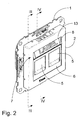
- Fig. 2 shows the information carrier in process of being moved between these two positions.
- the information carrier 7 is journalled using two axle journals 10 located in corresponding bearings formed by loops 11 at the end of springs 12.
- the springs 12 bias the information carrier 7 into engagement with the upper edge 13 and the lower edge 14 of the window 9.
- the corners of the triangular profile of the information carrier 7 have been removed to form recesses 15 adapted to engage said upper edge 13 and said lower edge 14 of the window to maintain the information carrier 7 flush with said first surface 6 of the detachable face plate 2.
- This engagement further more fixes the information carrier 7 against rotation unless deliberately acted upon by applying an external force.
- the at least one surface 8 may thus be retained in a stationary position during attachment of a label or during manual writing of text thereon. Due to the springs 12 the information carrier 7 may be kept flush with respect to the first surface 6 and in engagement with the upper edge 13 and the lower edge 14 of the window 9 irrespective how deep the detachable face plate 2 is held in engagement with the main body part 1 by means of the releasable latches 3b.
- FIGs. 5-7d illustrate a second embodiment of the invention, which will now be explained. To avoid unnecessary repetition, focus will be on the differences from the first embodiment of Figs. 1-4 and for that reason corresponding elements will be designated with the same reference numerals.
- FIG. 5 there is shown a mains outlet with a single socket 4 for receiving a three pronged single phase mains plug with semi-circular ground prong as commonly used in Denmark.
- Figs. 6a which is cross sectional view of the outlet of Fig. 5 taken along the line VI-VI of that figure, further differences that those relating directly to the nature of the outlet, i.e. mains vs. RJ45, will become apparent.
- the information carrier 7 has two parallel sides, at lease one of which is a surface 8 for holding the information.
- the at least one surface 8 preferably being a flat surface for receiving a sticky label or adapted for being written directly on.
- the information carrier 7 is rotably journalled about a first axis A (see Fig. 7a ) between a first position shown in Fig. 6b , and a second position (not shown), in which the information faces towards the main body part 1 in a cavity 16 and is not visible in the window 9. In that second position the information written on or attached to the at least one surface 8 is well protected against external influences in the cavity 16.
- 6a shows the information carrier 7 in an intermediate position in the process of being moved between said first position and said second position or vice versa.
- a detachable face plate 2 is attached to the main body part using latches 3 engaging appropriate counterparts on the main body part 1.
- the axis A is preferably located so that in either of the first and second positions the at least one surface 8 presented in the window 9 is flush with an essentially plane first surface 6 extending in a first plane.
- Figs. 7a-7d show the outlet of Fig. 5 with the detachable face plate 2 removed.
- the information carrier 7 is preferably hollow with one or more cross sectional ribs for stability. This saves weight and material.
- the information carrier 7 is rotably journalled about a first axis A, the first axis extending in parallel with said first surface 6.
- the information carrier 7 is journalled using two axle journals 10 located in corresponding bearings.
- the bearings are formed between two spring arms 17, which are preferably provided as an integral part of the main body during moulding thereof. Unlike the first embodiment these spring arms 17 are not adapted to keep the at least one surface biased towards the window 9 in the face plate 2 and flush with the first surface 6.
- Fig. 8 a third embodiment of the outlet according to the invention is shown.
- the third embodiment essentially only differs from that of Fig. 5 in that the outlet is adapted for RJ45 sockets and not mains.
- Fig. 8 thus serves to illustrate that features are freely interchangeable between various embodiments, at that the invention is not limited to use with specific sockets.
- the detachable face plate 2 is only optional. Without deviation from the gist of the invention, the first surface 6 extending in a first plane could just as well be formed as an integral part of the main body.
Landscapes
- Engineering & Computer Science (AREA)
- Architecture (AREA)
- Civil Engineering (AREA)
- Structural Engineering (AREA)
- Connector Housings Or Holding Contact Members (AREA)
- Details Of Connecting Devices For Male And Female Coupling (AREA)
Description
- The present invention relates to an electrical outlet comprising at least one socket adapted to receive an electrical plug, said outlet comprising a main body part and a first surface extending essentially in a first plane, where said first surface comprises a window, and at least one opening through which said plug may be inserted into said socket so as to establish a desired electrical connection, and where said main body part comprises an information carrier allowing the provision of information relating to said desired electrical connection in said window, said information carrier comprises a movable member movable with respect to said main body part.
- Electrical outlets come in many different variations, and the term is here to be construed in the broadest sense, covering inter alia electrical mains outlets, outlets for telephones and telecommunications, television, radio, audio etc. mounted in or on walls and as part of switch cabinets.
- When many of such outlets are found close to another it may be necessary to be able to identify each particular one of them. An example could be outlets with RJ45 sockets used for Ethernet in office environments. In each office or meeting room there may be several outlets with RJ45 sockets located side by side mounted on or in a wall or in a cable duct, and all appearing visually identical. Some, however, may used for telephone or fax whereas others may be used for internal or external Ethernet communication. Which one does which depends on the actual cabling in the wall or duct, which in turn may depend on the configuration of patch cables between similarly identical outlets in a distribution cabinet located elsewhere. In either case the problem remains the same, each outlet needs to be marked so that it can be identified for use and/or in particular for service and re-patching in the future.
- Prior art outlets with fields for marking, such as transparent windows, behind which, a piece of paper or the like, such as a DYMO® strip, on which the marking is written, may be placed, are known. Often, however, an adhesive label or a DYMO® strip is simply stuck on front of the outlet.
- Such markings, however, are prone to getting unstuck over time, e.g. under the influence of water or the like from cleaning, as a result of excessive temperature affecting the adhesion, or as a result of deliberate peeling off by people who do not know better. Furthermore, such markings are also prone to fading of the written or printed text under the influence of light, in particular sunlight. In either of the above cases, the result is a loss of information. This loss of information is in particularly a problem, because after installation, the service or other occasion where the information is needed is often far in the future and no one, not even the technician who did the original the installation, will know the configuration -let alone his successor or an external technician.
- From
DE 0 352 347 is known an electrical outlet comprising an information carrier provided as a hinged flap for covering an opening through which a plug may be inserted to establish a desired electrical connection. - From
DE 103 18 329 is known an electrical outlet with a plate shaped window in a front plate and a plate shaped information carrier adapted to be positioned in the window of the front plate. A further electrical outlet of this kind is known fromUS 2008/0138573 , wherein information carrier comprises a slot for receiving a label prior to the positioning of the information carrier in a recess of a front plate. - Based on this, it is the object of the present invention to provide an electrical outlet, which overcome the above problem with potential loss of information.
- According to the present invention this object is achieved with an electrical outlet according to the opening paragraph, wherein said information carrier is rotary movable about a first axis extending in parallel with said first plane so that the information may be hidden away.
- Thereby the information may be hidden away out of reach of bleaching sunlight, external influences like water from cleaning, deliberate peeling of the labelling and many other influences, but still be accessible to the technician who needs the information. In this way the side with the marking may simply be turned into the outlet away from said light and other influences. Making the information carrier rotary movable, is particularly advantageous, because it does not take up more space on or behind the first surface than is actually necessary.
- According to a further preferred embodiment, the information carrier is rotary movable through an angle between a first position and a second position. This allows the back of the information carrier to be flush with the first surface, while the information front side carrying the information is safely hidden and protected.
- According to a further preferred embodiment said information carrier has means for retaining at least one of said first and second positions. This allows the information carrier to be held in a somewhat fixed position during labelling or while text is manually written thereon.
- According to yet another embodiment, said detachable face plate comprises at least one removable cover adapted to cover said at least one socket. This allows the protection of sockets not in use, i.e. in which no plugs are inserted, against dust, dirt and the insertion of foreign objects.
- According to a preferred embodiment, the socket is provided with a colour coding in a colour differing from said first surface. This allow for the immediate identification of the overall nature of the desired connection.
- According to yet a further preferred embodiment, said information carrier is adapted to be released from said main body part and reengaged in said main body part after a rotation through 180 degrees about a second axis perpendicular to said first axis. This allows the information carrier to be reversed into the opposite orientation, which, in turn, allows for deactivation of said means for retaining the information carrier in position.
- According to another embodiment, said electrical outlet comprises a detachable face plate. This allows the establishment of an essentially flush, flat surface constituting said first surface, while still making the access to the information carrier easy when labelling it. Moreover it visually hides the fact that the information carrier is releasable and helps to cover the immediate access to the them, thus rendering the appearance of the installation device better and unauthorised persons less likely to tamper with the information carrier, except of course turning it about the first axis.
- The invention will now be described in greater detail based on non-limiting exemplary embodiments and with reference to the drawings, on which
-
Fig. 1 shows an exploded view of a first embodiment of an outlet according to the invention, -
Fig. 2 shows an assembled view of the outlet ofFig. 2 , -
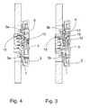
Fig. 3 shows a first cross section of the outlet ofFig. 2 taken along the line III-III, -
Fig. 4 shows a second cross section of the outlet ofFig. 2 taken along the line IV-IV, -
Fig. 5 shows a second embodiment of an outlet according to the invention, -
Figs. 6a and 6b show a cross section of the outlet ofFig. 5 taken along the line VI-VI with the information carrier in two different positions, -
Figs. 7a-7d illustrate how the information carrier of the outlet ofFig. 5 may be reversed, and -
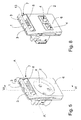
Fig. 8 shows a third embodiment of an outlet according to the invention. -
Figs. 1-4 show a first embodiment of an outlet according to the invention. Turning first toFig. 1 , an exploded view of a first embodiment of an outlet according to the invention is shown. The outlet comprises amain body part 1 and adetachable face plate 2 having an essentially planefirst surface 6 extending in a first plane. Thedetachable face plate 2 may be attached to and detached from themain body part 1 by means ofreleasable latches main body part 1. Thereleasable latches 3b are provided with steps in order to control the depth of the engagement between thedetachable face plate 2 and themain body part 1. The electrical outlet shown comprises twosockets 4 each adapted to receive an electrical plug (not shown), e.g. an RJ45 plug. Thesockets 4 are accessible through appropriate openings in thedetachable face place 2, after removal ofremovable covers 5, so as to allow a plug to be inserted into saidsocket 4 in order to establish a desired electrical connection. Theremovable covers 5 are optional, but useful in covering, and thus protecting, unusedsockets 4 against intrusion of dust, dirt and the like as well as against damage from insertion of foreign objects. Moreover, the covers may be helpful in identifying, immediately and irrespective of any other labelling,sockets 4, which are not in use, i.e. not electrically connected to anything, and therefore are not capable of establishing said desired connection. Moreover, thecovers 5 may carry an indication of the overall nature of desired connection for which the sockets are in use, e.g. by comprising a selected colour coding in a colour differing from the colour of said first surface. - Taking as an example the RJ45 plug mentioned above, such an RJ45 plug may be inserted into any one of a number of
corresponding RJ45 sockets 4 with identical appearance such as the two shown inFig. 1 but each one configured to different desired electrical connections. One could e.g. be configured as an ISDN telephone socket and the other as an Ethernet LAN socket, a possible third could be an Ethernet WAN socket and a possible fourth could be a redundant non-configured socket, as mentioned above. By the use of different indicators such as a colour or a symbol in relation to the socket these four types, i.e. the overall functionality, will be readily distinguishable. - However, for easy and full identification it is furthermore desirable to identify the
different sockets 4 more precisely, e.g. by labelling them, so that finding exactly the correct desired connection through a trial-and-error process of repeated insertion and testing is avoided. That is to say, the labelling should reflect the configuration of patch cables between similarly identical outlets in a distribution cabinet located elsewhere. Evidently, these similar outlets in the distribution cabinet would bear corresponding labelling. As mentioned above such labelling should be stable and secure for long time periods, irrespective whether the outlet is mounted in a wall, in a cable duct, in a distribution cabinet or anywhere else where the information is needed. - For such labelling the outlet according to the invention comprises an
information carrier 7. Theinformation carrier 7 ofFig. 1 comprises an elongated member with a generally triangular cross section, with at least onesurface 8 for holding the information. Thesurface 8 is preferably a flat surface for receiving a sticky label or adapted for being written directly on. - The
information carrier 7 is movable with respect to saidmain body 1 part so that it may occupy at least a first position and a second position with respect to saidmain body 1. The first position being a position in which the at least onesurface 8 extends essentially in parallel and preferably flush with saidfirst surface 6 so as to allow the information provided on said at least onesurface 8 to be visible in or through awindow 9 provided in thefirst surface 6. The second position being a position in which the information provided on said at least onesurface 8 faces away from thewindow 9 provided in thefirst surface 6, so as to render the information invisible and protect any labelling against external influences. - In the embodiment of
Fig. 1 , theinformation carrier 7 is movable between said first position and said second position by rotation about an axis A extending in parallel with said first surface.Fig. 2 shows the information carrier in process of being moved between these two positions. In the embodiment illustrated inFig. 1 , theinformation carrier 7 is journalled using twoaxle journals 10 located in corresponding bearings formed byloops 11 at the end ofsprings 12. Thesprings 12 bias theinformation carrier 7 into engagement with theupper edge 13 and thelower edge 14 of thewindow 9. Preferably the corners of the triangular profile of theinformation carrier 7 have been removed to formrecesses 15 adapted to engage saidupper edge 13 and saidlower edge 14 of the window to maintain theinformation carrier 7 flush with saidfirst surface 6 of thedetachable face plate 2. This engagement further more fixes theinformation carrier 7 against rotation unless deliberately acted upon by applying an external force. The at least onesurface 8 may thus be retained in a stationary position during attachment of a label or during manual writing of text thereon. Due to thesprings 12 theinformation carrier 7 may be kept flush with respect to thefirst surface 6 and in engagement with theupper edge 13 and thelower edge 14 of thewindow 9 irrespective how deep thedetachable face plate 2 is held in engagement with themain body part 1 by means of thereleasable latches 3b. - The skilled person will realise that the illustrated bearings with
loops 11 and springs 12 is only one possible embodiment, and that other bearings could be used instead, in particular but not exclusively those, which will be explained in conjunction with other preferred embodiments below. -
Figs. 5-7d illustrate a second embodiment of the invention, which will now be explained. To avoid unnecessary repetition, focus will be on the differences from the first embodiment ofFigs. 1-4 and for that reason corresponding elements will be designated with the same reference numerals. - Looking first at
Fig. 5 , there is shown a mains outlet with asingle socket 4 for receiving a three pronged single phase mains plug with semi-circular ground prong as commonly used in Denmark. Turning then toFigs. 6a , which is cross sectional view of the outlet ofFig. 5 taken along the line VI-VI of that figure, further differences that those relating directly to the nature of the outlet, i.e. mains vs. RJ45, will become apparent. - Looking at
Fig. 6 , it will inter alia be immediately apparent that rather than a triangular cross section, theinformation carrier 7 has two parallel sides, at lease one of which is asurface 8 for holding the information. The at least onesurface 8 preferably being a flat surface for receiving a sticky label or adapted for being written directly on. Theinformation carrier 7 is rotably journalled about a first axis A (seeFig. 7a ) between a first position shown inFig. 6b , and a second position (not shown), in which the information faces towards themain body part 1 in acavity 16 and is not visible in thewindow 9. In that second position the information written on or attached to the at least onesurface 8 is well protected against external influences in thecavity 16.Fig. 6a shows theinformation carrier 7 in an intermediate position in the process of being moved between said first position and said second position or vice versa. As can also be seen adetachable face plate 2 is attached to the main bodypart using latches 3 engaging appropriate counterparts on themain body part 1. The axis A is preferably located so that in either of the first and second positions the at least onesurface 8 presented in thewindow 9 is flush with an essentially planefirst surface 6 extending in a first plane. -
Figs. 7a-7d show the outlet ofFig. 5 with thedetachable face plate 2 removed. Here it can be seen that theinformation carrier 7 is preferably hollow with one or more cross sectional ribs for stability. This saves weight and material. As already mentioned, theinformation carrier 7 is rotably journalled about a first axis A, the first axis extending in parallel with saidfirst surface 6. Like in the first embodiment theinformation carrier 7 is journalled using twoaxle journals 10 located in corresponding bearings. However, the bearings are formed between twospring arms 17, which are preferably provided as an integral part of the main body during moulding thereof. Unlike the first embodiment thesespring arms 17 are not adapted to keep the at least one surface biased towards thewindow 9 in theface plate 2 and flush with thefirst surface 6. Instead, as can be seen fromFig. 7b and 7c , it allows the information carrier to be removed from the bearings formed between thespring arms 17 and turned 180 degrees about a second axis B perpendicular to the first axis A. Subsequently it may then be reinserted in the bearings formed between thespring arms 17 in a reverse orientation. This, in turn, allows for a relocation of theprotrusion 18 seen inFigs. 7c and 7d with respect to anotch 19 and agroove 20 provided in thewall 21 of thecavity 16. This provides the option of locking the information carrier in a desired position. Thereby it also becomes optional which side of the information carrier should face inward when theinformation carrier 7 is retained in the first or second position. It should of course be noted that irrespective of the overall embodiment of the outlet, simple friction could also constitute a means for retaining the information carrier in a desired position. - This arrangement is also the reason why a
removal face plate 2 is preferred over an integral, because theremovable face plate 2 visually hides thespring arms 17 and helps to cover the immediate access to the them, thus rendering the appearance of the installation device better and unauthorised persons less likely to tamper with theinformation carrier 7, except of course turning it about the first axis A. - In
Fig. 8 a third embodiment of the outlet according to the invention is shown. The third embodiment essentially only differs from that ofFig. 5 in that the outlet is adapted for RJ45 sockets and not mains.Fig. 8 thus serves to illustrate that features are freely interchangeable between various embodiments, at that the invention is not limited to use with specific sockets. - It should also be noted that the
detachable face plate 2 is only optional. Without deviation from the gist of the invention, thefirst surface 6 extending in a first plane could just as well be formed as an integral part of the main body.
Claims (6)
- An electrical outlet comprising at least one socket (4) adapted to receive an electrical plug,
said outlet comprising a main body (1) part and a first surface (6) extending essentially in a first plane, where
said first surface (6) comprises a window (9), and at least one opening through which said plug may be inserted into said socket (4) so as to establish a desired electrical connection, and where
said main body (1) part comprises an information carrier allowing (7) the provision of information relating to said desired electrical connection in said window (9),
said information carrier (7) comprises a movable member movable with respect to said main body part (1), characterized in that
said information carrier (7) is rotary movable about a first axis (A) extending in parallel with said first plane so that the information may be hidden away. - An electrical outlet according to claim 1, wherein said information carrier (7) is rotary movable through an angle between a first position and a second position.
- An electrical outlet according to claim 2, wherein said information carrier (7) has means (15, 18) for retaining at least one of said first and second positions.
- An electrical outlet according to claim 3, wherein said detachable face plate (2) comprises at least one removable cover (5) adapted to cover said at least one socket (4).
- An electrical outlet according to any one of claims 1-4, wherein said information carrier (7) is adapted to be released from said main body part (1) and reengaged in said main body part (1) after a rotation through 180 degrees about a second axis (B) perpendicular to said first axis (A).
- An electrical outlet according to any one of the preceding claims comprising a detachable face plate (2).
Priority Applications (6)
| Application Number | Priority Date | Filing Date | Title |
|---|---|---|---|
| EP09176359A EP2325963B1 (en) | 2009-11-18 | 2009-11-18 | Electrical outlet with information carrier |
| ES09176359T ES2406708T3 (en) | 2009-11-18 | 2009-11-18 | Electrical outlet with information support |
| DK09176359.9T DK2325963T3 (en) | 2009-11-18 | 2009-11-18 | Electrical socket comprising an information carrier |
| BR112012011836-6A BR112012011836B1 (en) | 2009-11-18 | 2010-11-16 | ELECTRICAL OUTPUT WITH INFORMATION CARRIER |
| PCT/DK2010/050309 WO2011060790A1 (en) | 2009-11-18 | 2010-11-16 | Electrical outlet with information carrier |
| RU2012124559/07A RU2535300C2 (en) | 2009-11-18 | 2010-11-16 | Power receptacle with data carrier |
Applications Claiming Priority (1)
| Application Number | Priority Date | Filing Date | Title |
|---|---|---|---|
| EP09176359A EP2325963B1 (en) | 2009-11-18 | 2009-11-18 | Electrical outlet with information carrier |
Publications (2)
| Publication Number | Publication Date |
|---|---|
| EP2325963A1 EP2325963A1 (en) | 2011-05-25 |
| EP2325963B1 true EP2325963B1 (en) | 2013-02-27 |
Family
ID=42103893
Family Applications (1)
| Application Number | Title | Priority Date | Filing Date |
|---|---|---|---|
| EP09176359A Not-in-force EP2325963B1 (en) | 2009-11-18 | 2009-11-18 | Electrical outlet with information carrier |
Country Status (6)
| Country | Link |
|---|---|
| EP (1) | EP2325963B1 (en) |
| BR (1) | BR112012011836B1 (en) |
| DK (1) | DK2325963T3 (en) |
| ES (1) | ES2406708T3 (en) |
| RU (1) | RU2535300C2 (en) |
| WO (1) | WO2011060790A1 (en) |
Families Citing this family (6)
| Publication number | Priority date | Publication date | Assignee | Title |
|---|---|---|---|---|
| DE102013100909B3 (en) * | 2013-01-30 | 2014-01-02 | Albrecht Jung Gmbh & Co Kg | Electrical installation device e.g. switch, has recess acting together with sliding piece comprising multi-stage internal tooth that act together with multi-stage external tooth of holding element, where holding element is fixed to support |
| FR3051291B1 (en) * | 2016-05-13 | 2018-04-20 | Groupe Adeo | CONVERGENCE OF MASKS FOR ELECTRICAL EQUIPMENT |
| FR3059842B1 (en) * | 2016-12-02 | 2019-01-25 | Legrand France | CLADDING PLATE, ELECTRICAL EQUIPMENT COMPRISING SUCH A WAFER PLATE AND METHOD OF MANUFACTURING A WAFER PLATE |
| TR201705890A2 (en) * | 2017-04-20 | 2017-07-21 | Eae Teknoloji Arastirma Gelistirme Sanayi Ve Ticaret Anonim Sirketi | AN INSTALLATION APPARATUS |
| RU180027U1 (en) * | 2017-06-02 | 2018-05-31 | Василий Мотелевич Оснач | Electrical connector |
| FR3159712A1 (en) * | 2024-02-26 | 2025-08-29 | Legrand France | Assembly formed of a support plate intended to support electrical equipment, a covering plate and an additional functional component |
Family Cites Families (5)
| Publication number | Priority date | Publication date | Assignee | Title |
|---|---|---|---|---|
| EP0352347A1 (en) | 1988-07-27 | 1990-01-31 | C.A. Weidmüller GmbH & Co. | Electrical connector |
| IT1310142B1 (en) * | 1999-08-20 | 2002-02-11 | Merloni Elettrodomestici Spa | DEVICE, SYSTEM AND METHOD FOR THE MONITORING OF A DOMESTIC ELECTRICITY USE, IN PARTICULAR A HOUSEHOLD APPLIANCE. |
| US6718674B2 (en) | 2002-03-21 | 2004-04-13 | Panduit Corp. | Apparatus and system for identification labeling |
| DE10318329B4 (en) | 2003-04-19 | 2016-03-31 | Merten Gmbh & Co. Kg | Electrical installation device with shield |
| ES1065814Y (en) * | 2007-06-25 | 2008-02-01 | Unex Aparellaje Electrico Sl | BOX FOR ELECTRICAL MECHANISMS |
-
2009
- 2009-11-18 ES ES09176359T patent/ES2406708T3/en active Active
- 2009-11-18 DK DK09176359.9T patent/DK2325963T3/en active
- 2009-11-18 EP EP09176359A patent/EP2325963B1/en not_active Not-in-force
-
2010
- 2010-11-16 BR BR112012011836-6A patent/BR112012011836B1/en not_active IP Right Cessation
- 2010-11-16 RU RU2012124559/07A patent/RU2535300C2/en active
- 2010-11-16 WO PCT/DK2010/050309 patent/WO2011060790A1/en not_active Ceased
Also Published As
| Publication number | Publication date |
|---|---|
| ES2406708T3 (en) | 2013-06-07 |
| EP2325963A1 (en) | 2011-05-25 |
| RU2535300C2 (en) | 2014-12-10 |
| BR112012011836A2 (en) | 2016-03-15 |
| BR112012011836B1 (en) | 2019-08-20 |
| DK2325963T3 (en) | 2013-04-29 |
| RU2012124559A (en) | 2013-12-27 |
| WO2011060790A1 (en) | 2011-05-26 |
Similar Documents
| Publication | Publication Date | Title |
|---|---|---|
| EP2325963A1 (en) | Electrical outlet with information carrier | |
| US7007422B2 (en) | Apparatus and system for identification labeling | |
| US6172301B1 (en) | Receptacle faceplate | |
| US10522939B2 (en) | Cover assembly for a telecommunications connector | |
| AU645088B2 (en) | Panel yoke | |
| US20220342169A1 (en) | Indicia and method for identifying telecommunications components | |
| US7612288B1 (en) | Techniques for attaching a label to an electronic cable | |
| US9832542B2 (en) | Patch panel system and jack module attachment thereto | |
| EP3102971B1 (en) | Rack mountable optical fiber enclosure | |
| GB2298972A (en) | Strain relief boot | |
| JP2010113293A (en) | Optical connection cable clamping member | |
| CA2980144C (en) | Data communication port insert configurable with indicia to customize data communication station labeling and identification | |
| CA2678609A1 (en) | Electrical component labeling system | |
| CA2982506C (en) | Extension cord, socket and cover of a socket | |
| CA2676764A1 (en) | Voice and data patch panel having a bracket for structured wire enclosures | |
| US6683252B2 (en) | Latching device for a circuit pack | |
| JP5903125B2 (en) | Management instrument after removing instrument | |
| JP2020048357A (en) | Floor electric outlet | |
| KR101633090B1 (en) | Cable Duct With Cable Labelling Tap | |
| US6997738B1 (en) | Wire-identification plugs for electronic devices | |
| US20170241620A1 (en) | Attachment for outlets, light switches, and other fixtures to aid locating and use | |
| US20200028340A1 (en) | Cover plate with circuit label opening | |
| JP5390582B2 (en) | Light outlet | |
| US12211401B2 (en) | Identification system for recessed floor fitting | |
| KR200384336Y1 (en) | Wiring Duct for Desk |
Legal Events
| Date | Code | Title | Description |
|---|---|---|---|
| PUAI | Public reference made under article 153(3) epc to a published international application that has entered the european phase |
Free format text: ORIGINAL CODE: 0009012 |
|
| AK | Designated contracting states |
Kind code of ref document: A1 Designated state(s): AT BE BG CH CY CZ DE DK EE ES FI FR GB GR HR HU IE IS IT LI LT LU LV MC MK MT NL NO PL PT RO SE SI SK SM TR |
|
| 17P | Request for examination filed |
Effective date: 20110930 |
|
| 17Q | First examination report despatched |
Effective date: 20120127 |
|
| REG | Reference to a national code |
Ref country code: DE Ref legal event code: R079 Ref document number: 602009013611 Country of ref document: DE Free format text: PREVIOUS MAIN CLASS: H02G0003140000 Ipc: H01R0013460000 |
|
| GRAP | Despatch of communication of intention to grant a patent |
Free format text: ORIGINAL CODE: EPIDOSNIGR1 |
|
| RIC1 | Information provided on ipc code assigned before grant |
Ipc: H02G 3/12 20060101ALI20120516BHEP Ipc: H02G 3/14 20060101ALI20120516BHEP Ipc: H01R 13/46 20060101AFI20120516BHEP Ipc: H01R 9/24 20060101ALI20120516BHEP |
|
| GRAS | Grant fee paid |
Free format text: ORIGINAL CODE: EPIDOSNIGR3 |
|
| GRAA | (expected) grant |
Free format text: ORIGINAL CODE: 0009210 |
|
| AK | Designated contracting states |
Kind code of ref document: B1 Designated state(s): AT BE BG CH CY CZ DE DK EE ES FI FR GB GR HR HU IE IS IT LI LT LU LV MC MK MT NL NO PL PT RO SE SI SK SM TR |
|
| REG | Reference to a national code |
Ref country code: GB Ref legal event code: FG4D |
|
| REG | Reference to a national code |
Ref country code: CH Ref legal event code: EP |
|
| REG | Reference to a national code |
Ref country code: AT Ref legal event code: REF Ref document number: 598919 Country of ref document: AT Kind code of ref document: T Effective date: 20130315 |
|
| REG | Reference to a national code |
Ref country code: IE Ref legal event code: FG4D |
|
| REG | Reference to a national code |
Ref country code: DE Ref legal event code: R096 Ref document number: 602009013611 Country of ref document: DE Effective date: 20130425 |
|
| REG | Reference to a national code |
Ref country code: DK Ref legal event code: T3 |
|
| REG | Reference to a national code |
Ref country code: SE Ref legal event code: TRGR |
|
| REG | Reference to a national code |
Ref country code: ES Ref legal event code: FG2A Ref document number: 2406708 Country of ref document: ES Kind code of ref document: T3 Effective date: 20130607 |
|
| REG | Reference to a national code |
Ref country code: NO Ref legal event code: T2 Effective date: 20130227 |
|
| REG | Reference to a national code |
Ref country code: AT Ref legal event code: MK05 Ref document number: 598919 Country of ref document: AT Kind code of ref document: T Effective date: 20130227 |
|
| REG | Reference to a national code |
Ref country code: LT Ref legal event code: MG4D |
|
| PG25 | Lapsed in a contracting state [announced via postgrant information from national office to epo] |
Ref country code: AT Free format text: LAPSE BECAUSE OF FAILURE TO SUBMIT A TRANSLATION OF THE DESCRIPTION OR TO PAY THE FEE WITHIN THE PRESCRIBED TIME-LIMIT Effective date: 20130227 Ref country code: IS Free format text: LAPSE BECAUSE OF FAILURE TO SUBMIT A TRANSLATION OF THE DESCRIPTION OR TO PAY THE FEE WITHIN THE PRESCRIBED TIME-LIMIT Effective date: 20130627 Ref country code: BG Free format text: LAPSE BECAUSE OF FAILURE TO SUBMIT A TRANSLATION OF THE DESCRIPTION OR TO PAY THE FEE WITHIN THE PRESCRIBED TIME-LIMIT Effective date: 20130527 Ref country code: LT Free format text: LAPSE BECAUSE OF FAILURE TO SUBMIT A TRANSLATION OF THE DESCRIPTION OR TO PAY THE FEE WITHIN THE PRESCRIBED TIME-LIMIT Effective date: 20130227 |
|
| REG | Reference to a national code |
Ref country code: NL Ref legal event code: VDEP Effective date: 20130227 |
|
| PG25 | Lapsed in a contracting state [announced via postgrant information from national office to epo] |
Ref country code: PT Free format text: LAPSE BECAUSE OF FAILURE TO SUBMIT A TRANSLATION OF THE DESCRIPTION OR TO PAY THE FEE WITHIN THE PRESCRIBED TIME-LIMIT Effective date: 20130627 Ref country code: BE Free format text: LAPSE BECAUSE OF FAILURE TO SUBMIT A TRANSLATION OF THE DESCRIPTION OR TO PAY THE FEE WITHIN THE PRESCRIBED TIME-LIMIT Effective date: 20130227 Ref country code: GR Free format text: LAPSE BECAUSE OF FAILURE TO SUBMIT A TRANSLATION OF THE DESCRIPTION OR TO PAY THE FEE WITHIN THE PRESCRIBED TIME-LIMIT Effective date: 20130528 Ref country code: PL Free format text: LAPSE BECAUSE OF FAILURE TO SUBMIT A TRANSLATION OF THE DESCRIPTION OR TO PAY THE FEE WITHIN THE PRESCRIBED TIME-LIMIT Effective date: 20130227 Ref country code: LV Free format text: LAPSE BECAUSE OF FAILURE TO SUBMIT A TRANSLATION OF THE DESCRIPTION OR TO PAY THE FEE WITHIN THE PRESCRIBED TIME-LIMIT Effective date: 20130227 Ref country code: SI Free format text: LAPSE BECAUSE OF FAILURE TO SUBMIT A TRANSLATION OF THE DESCRIPTION OR TO PAY THE FEE WITHIN THE PRESCRIBED TIME-LIMIT Effective date: 20130227 |
|
| PG25 | Lapsed in a contracting state [announced via postgrant information from national office to epo] |
Ref country code: HR Free format text: LAPSE BECAUSE OF FAILURE TO SUBMIT A TRANSLATION OF THE DESCRIPTION OR TO PAY THE FEE WITHIN THE PRESCRIBED TIME-LIMIT Effective date: 20130227 |
|
| PG25 | Lapsed in a contracting state [announced via postgrant information from national office to epo] |
Ref country code: NL Free format text: LAPSE BECAUSE OF FAILURE TO SUBMIT A TRANSLATION OF THE DESCRIPTION OR TO PAY THE FEE WITHIN THE PRESCRIBED TIME-LIMIT Effective date: 20130227 Ref country code: CZ Free format text: LAPSE BECAUSE OF FAILURE TO SUBMIT A TRANSLATION OF THE DESCRIPTION OR TO PAY THE FEE WITHIN THE PRESCRIBED TIME-LIMIT Effective date: 20130227 Ref country code: SK Free format text: LAPSE BECAUSE OF FAILURE TO SUBMIT A TRANSLATION OF THE DESCRIPTION OR TO PAY THE FEE WITHIN THE PRESCRIBED TIME-LIMIT Effective date: 20130227 Ref country code: RO Free format text: LAPSE BECAUSE OF FAILURE TO SUBMIT A TRANSLATION OF THE DESCRIPTION OR TO PAY THE FEE WITHIN THE PRESCRIBED TIME-LIMIT Effective date: 20130227 Ref country code: EE Free format text: LAPSE BECAUSE OF FAILURE TO SUBMIT A TRANSLATION OF THE DESCRIPTION OR TO PAY THE FEE WITHIN THE PRESCRIBED TIME-LIMIT Effective date: 20130227 |
|
| PG25 | Lapsed in a contracting state [announced via postgrant information from national office to epo] |
Ref country code: CY Free format text: LAPSE BECAUSE OF FAILURE TO SUBMIT A TRANSLATION OF THE DESCRIPTION OR TO PAY THE FEE WITHIN THE PRESCRIBED TIME-LIMIT Effective date: 20130227 |
|
| PG25 | Lapsed in a contracting state [announced via postgrant information from national office to epo] |
Ref country code: IT Free format text: LAPSE BECAUSE OF FAILURE TO SUBMIT A TRANSLATION OF THE DESCRIPTION OR TO PAY THE FEE WITHIN THE PRESCRIBED TIME-LIMIT Effective date: 20130227 |
|
| PLBE | No opposition filed within time limit |
Free format text: ORIGINAL CODE: 0009261 |
|
| STAA | Information on the status of an ep patent application or granted ep patent |
Free format text: STATUS: NO OPPOSITION FILED WITHIN TIME LIMIT |
|
| 26N | No opposition filed |
Effective date: 20131128 |
|
| REG | Reference to a national code |
Ref country code: DE Ref legal event code: R097 Ref document number: 602009013611 Country of ref document: DE Effective date: 20131128 |
|
| REG | Reference to a national code |
Ref country code: CH Ref legal event code: PL |
|
| PG25 | Lapsed in a contracting state [announced via postgrant information from national office to epo] |
Ref country code: LI Free format text: LAPSE BECAUSE OF NON-PAYMENT OF DUE FEES Effective date: 20131130 Ref country code: MC Free format text: LAPSE BECAUSE OF FAILURE TO SUBMIT A TRANSLATION OF THE DESCRIPTION OR TO PAY THE FEE WITHIN THE PRESCRIBED TIME-LIMIT Effective date: 20130227 Ref country code: CH Free format text: LAPSE BECAUSE OF NON-PAYMENT OF DUE FEES Effective date: 20131130 |
|
| REG | Reference to a national code |
Ref country code: FR Ref legal event code: ST Effective date: 20140731 |
|
| REG | Reference to a national code |
Ref country code: IE Ref legal event code: MM4A |
|
| PG25 | Lapsed in a contracting state [announced via postgrant information from national office to epo] |
Ref country code: IE Free format text: LAPSE BECAUSE OF NON-PAYMENT OF DUE FEES Effective date: 20131118 |
|
| PG25 | Lapsed in a contracting state [announced via postgrant information from national office to epo] |
Ref country code: FR Free format text: LAPSE BECAUSE OF NON-PAYMENT OF DUE FEES Effective date: 20131202 |
|
| PG25 | Lapsed in a contracting state [announced via postgrant information from national office to epo] |
Ref country code: SM Free format text: LAPSE BECAUSE OF FAILURE TO SUBMIT A TRANSLATION OF THE DESCRIPTION OR TO PAY THE FEE WITHIN THE PRESCRIBED TIME-LIMIT Effective date: 20130227 |
|
| PG25 | Lapsed in a contracting state [announced via postgrant information from national office to epo] |
Ref country code: TR Free format text: LAPSE BECAUSE OF FAILURE TO SUBMIT A TRANSLATION OF THE DESCRIPTION OR TO PAY THE FEE WITHIN THE PRESCRIBED TIME-LIMIT Effective date: 20130227 |
|
| PG25 | Lapsed in a contracting state [announced via postgrant information from national office to epo] |
Ref country code: LU Free format text: LAPSE BECAUSE OF NON-PAYMENT OF DUE FEES Effective date: 20131118 Ref country code: HU Free format text: LAPSE BECAUSE OF FAILURE TO SUBMIT A TRANSLATION OF THE DESCRIPTION OR TO PAY THE FEE WITHIN THE PRESCRIBED TIME-LIMIT; INVALID AB INITIO Effective date: 20091118 Ref country code: MK Free format text: LAPSE BECAUSE OF FAILURE TO SUBMIT A TRANSLATION OF THE DESCRIPTION OR TO PAY THE FEE WITHIN THE PRESCRIBED TIME-LIMIT Effective date: 20130227 |
|
| PG25 | Lapsed in a contracting state [announced via postgrant information from national office to epo] |
Ref country code: MT Free format text: LAPSE BECAUSE OF FAILURE TO SUBMIT A TRANSLATION OF THE DESCRIPTION OR TO PAY THE FEE WITHIN THE PRESCRIBED TIME-LIMIT Effective date: 20130227 |
|
| PGFP | Annual fee paid to national office [announced via postgrant information from national office to epo] |
Ref country code: FI Payment date: 20210125 Year of fee payment: 12 Ref country code: NO Payment date: 20210126 Year of fee payment: 12 |
|
| REG | Reference to a national code |
Ref country code: DE Ref legal event code: R082 Ref document number: 602009013611 Country of ref document: DE Representative=s name: KILBURN & STRODE LLP, NL |
|
| PGFP | Annual fee paid to national office [announced via postgrant information from national office to epo] |
Ref country code: GB Payment date: 20210120 Year of fee payment: 12 Ref country code: ES Payment date: 20210128 Year of fee payment: 12 Ref country code: SE Payment date: 20210126 Year of fee payment: 12 Ref country code: DE Payment date: 20210119 Year of fee payment: 12 Ref country code: DK Payment date: 20210126 Year of fee payment: 12 |
|
| REG | Reference to a national code |
Ref country code: DE Ref legal event code: R119 Ref document number: 602009013611 Country of ref document: DE |
|
| REG | Reference to a national code |
Ref country code: DK Ref legal event code: EBP Effective date: 20211130 |
|
| REG | Reference to a national code |
Ref country code: NO Ref legal event code: MMEP |
|
| REG | Reference to a national code |
Ref country code: FI Ref legal event code: MAE |
|
| GBPC | Gb: european patent ceased through non-payment of renewal fee |
Effective date: 20211118 |
|
| PG25 | Lapsed in a contracting state [announced via postgrant information from national office to epo] |
Ref country code: SE Free format text: LAPSE BECAUSE OF NON-PAYMENT OF DUE FEES Effective date: 20211119 Ref country code: NO Free format text: LAPSE BECAUSE OF NON-PAYMENT OF DUE FEES Effective date: 20211130 |
|
| PG25 | Lapsed in a contracting state [announced via postgrant information from national office to epo] |
Ref country code: FI Free format text: LAPSE BECAUSE OF NON-PAYMENT OF DUE FEES Effective date: 20211118 |
|
| PG25 | Lapsed in a contracting state [announced via postgrant information from national office to epo] |
Ref country code: GB Free format text: LAPSE BECAUSE OF NON-PAYMENT OF DUE FEES Effective date: 20211118 Ref country code: DK Free format text: LAPSE BECAUSE OF NON-PAYMENT OF DUE FEES Effective date: 20211130 Ref country code: DE Free format text: LAPSE BECAUSE OF NON-PAYMENT OF DUE FEES Effective date: 20220601 |
|
| REG | Reference to a national code |
Ref country code: ES Ref legal event code: FD2A Effective date: 20230224 |
|
| PG25 | Lapsed in a contracting state [announced via postgrant information from national office to epo] |
Ref country code: ES Free format text: LAPSE BECAUSE OF NON-PAYMENT OF DUE FEES Effective date: 20211119 |