EP2325925A1 - Electrode assembly and rechargeable battery using the same - Google Patents
Electrode assembly and rechargeable battery using the same Download PDFInfo
- Publication number
- EP2325925A1 EP2325925A1 EP10188980A EP10188980A EP2325925A1 EP 2325925 A1 EP2325925 A1 EP 2325925A1 EP 10188980 A EP10188980 A EP 10188980A EP 10188980 A EP10188980 A EP 10188980A EP 2325925 A1 EP2325925 A1 EP 2325925A1
- Authority
- EP
- European Patent Office
- Prior art keywords
- electrode
- electrode assembly
- uncoated region
- separator
- negative
- Prior art date
- Legal status (The legal status is an assumption and is not a legal conclusion. Google has not performed a legal analysis and makes no representation as to the accuracy of the status listed.)
- Granted
Links
Images



Classifications
-
- H—ELECTRICITY
- H01—ELECTRIC ELEMENTS
- H01M—PROCESSES OR MEANS, e.g. BATTERIES, FOR THE DIRECT CONVERSION OF CHEMICAL ENERGY INTO ELECTRICAL ENERGY
- H01M10/00—Secondary cells; Manufacture thereof
- H01M10/04—Construction or manufacture in general
- H01M10/0431—Cells with wound or folded electrodes
-
- H—ELECTRICITY
- H01—ELECTRIC ELEMENTS
- H01M—PROCESSES OR MEANS, e.g. BATTERIES, FOR THE DIRECT CONVERSION OF CHEMICAL ENERGY INTO ELECTRICAL ENERGY
- H01M10/00—Secondary cells; Manufacture thereof
- H01M10/05—Accumulators with non-aqueous electrolyte
- H01M10/052—Li-accumulators
-
- H—ELECTRICITY
- H01—ELECTRIC ELEMENTS
- H01M—PROCESSES OR MEANS, e.g. BATTERIES, FOR THE DIRECT CONVERSION OF CHEMICAL ENERGY INTO ELECTRICAL ENERGY
- H01M10/00—Secondary cells; Manufacture thereof
- H01M10/05—Accumulators with non-aqueous electrolyte
- H01M10/058—Construction or manufacture
- H01M10/0587—Construction or manufacture of accumulators having only wound construction elements, i.e. wound positive electrodes, wound negative electrodes and wound separators
-
- H—ELECTRICITY
- H01—ELECTRIC ELEMENTS
- H01M—PROCESSES OR MEANS, e.g. BATTERIES, FOR THE DIRECT CONVERSION OF CHEMICAL ENERGY INTO ELECTRICAL ENERGY
- H01M50/00—Constructional details or processes of manufacture of the non-active parts of electrochemical cells other than fuel cells, e.g. hybrid cells
- H01M50/40—Separators; Membranes; Diaphragms; Spacing elements inside cells
- H01M50/46—Separators, membranes or diaphragms characterised by their combination with electrodes
-
- H—ELECTRICITY
- H01—ELECTRIC ELEMENTS
- H01M—PROCESSES OR MEANS, e.g. BATTERIES, FOR THE DIRECT CONVERSION OF CHEMICAL ENERGY INTO ELECTRICAL ENERGY
- H01M10/00—Secondary cells; Manufacture thereof
- H01M10/42—Methods or arrangements for servicing or maintenance of secondary cells or secondary half-cells
- H01M10/4235—Safety or regulating additives or arrangements in electrodes, separators or electrolyte
-
- Y—GENERAL TAGGING OF NEW TECHNOLOGICAL DEVELOPMENTS; GENERAL TAGGING OF CROSS-SECTIONAL TECHNOLOGIES SPANNING OVER SEVERAL SECTIONS OF THE IPC; TECHNICAL SUBJECTS COVERED BY FORMER USPC CROSS-REFERENCE ART COLLECTIONS [XRACs] AND DIGESTS
- Y02—TECHNOLOGIES OR APPLICATIONS FOR MITIGATION OR ADAPTATION AGAINST CLIMATE CHANGE
- Y02E—REDUCTION OF GREENHOUSE GAS [GHG] EMISSIONS, RELATED TO ENERGY GENERATION, TRANSMISSION OR DISTRIBUTION
- Y02E60/00—Enabling technologies; Technologies with a potential or indirect contribution to GHG emissions mitigation
- Y02E60/10—Energy storage using batteries
-
- Y—GENERAL TAGGING OF NEW TECHNOLOGICAL DEVELOPMENTS; GENERAL TAGGING OF CROSS-SECTIONAL TECHNOLOGIES SPANNING OVER SEVERAL SECTIONS OF THE IPC; TECHNICAL SUBJECTS COVERED BY FORMER USPC CROSS-REFERENCE ART COLLECTIONS [XRACs] AND DIGESTS
- Y02—TECHNOLOGIES OR APPLICATIONS FOR MITIGATION OR ADAPTATION AGAINST CLIMATE CHANGE
- Y02P—CLIMATE CHANGE MITIGATION TECHNOLOGIES IN THE PRODUCTION OR PROCESSING OF GOODS
- Y02P70/00—Climate change mitigation technologies in the production process for final industrial or consumer products
- Y02P70/50—Manufacturing or production processes characterised by the final manufactured product
-
- Y—GENERAL TAGGING OF NEW TECHNOLOGICAL DEVELOPMENTS; GENERAL TAGGING OF CROSS-SECTIONAL TECHNOLOGIES SPANNING OVER SEVERAL SECTIONS OF THE IPC; TECHNICAL SUBJECTS COVERED BY FORMER USPC CROSS-REFERENCE ART COLLECTIONS [XRACs] AND DIGESTS
- Y02—TECHNOLOGIES OR APPLICATIONS FOR MITIGATION OR ADAPTATION AGAINST CLIMATE CHANGE
- Y02T—CLIMATE CHANGE MITIGATION TECHNOLOGIES RELATED TO TRANSPORTATION
- Y02T10/00—Road transport of goods or passengers
- Y02T10/60—Other road transportation technologies with climate change mitigation effect
- Y02T10/70—Energy storage systems for electromobility, e.g. batteries
Definitions
- the present invention relates to an electrode assembly and a rechargeable battery using the same. More particularly, the present invention relates to an electrode assembly having an improved structure and a rechargeable battery using the same.
- a rechargeable battery can be repeatedly charged and discharged.
- Low-capacity rechargeable batteries are used for portable compact electronic apparatuses such as mobile phones, notebook computers, and camcorders, and high-capacity rechargeable batteries are widely used as a power source for driving a motor of a hybrid vehicle, etc.
- the high-power rechargeable battery is constructed with a high-capacity rechargeable battery having a plurality of rechargeable cells coupled to each other in series such that it can be used as the power supply for driving motors in electric vehicles requiring high power.
- one high-capacity rechargeable battery is commonly formed with a plurality of rechargeable cells coupled to each other in series.
- the rechargeable battery may have a cylindrical shape, a prismatic shape, a pouch shape, etc.
- An electrode assembly includes a positive electrode, a negative electrode, and a separator disposed between the positive and negative electrodes.
- the separator separates the positive electrode and the negative electrode to prevent a short-circuit therebetween, and absorbs electrolyte required for a battery reaction to maintain high ion conductivity.
- the separator When internal temperature of the rechargeable battery increases due to overcharge, the separator may contract or be melted so that a short-circuit may occur between the positive electrode and the negative electrode. When the short-circuit occurs, the internal temperature of the rechargeable battery is rapidly increased so that the rechargeable battery may combust or explode.
- the short-circuit includes a short-circuit between a positive active material layer and a negative active material layer, a short-circuit between a positive active material layer and a negative current collector, a short-circuit between a negative active material layer and a positive current collector, and a short-circuit between a positive current collector and a negative current collector.
- the positive uncoated region and the negative uncoated region are respectively formed at opposite sides of the electrode assembly, the positive uncoated region and the negative active material layer may possibly be short-circuited rather than the positive and negative current collectors being short-circuited.
- the positive uncoated region and the negative active material layer are short-circuited, excessive heat is generated so that the rechargeable battery may combust or explode.
- the present invention has been made in an effort to provide an electrode assembly and a rechargeable battery with improved safety.
- An electrode assembly includes a positive electrode, a negative electrode, and a separator.
- a positive uncoated region where a positive active material layer is not formed is formed at one side of the positive electrode.
- a first negative uncoated region where a negative active material layer is not formed is formed at the other side of the negative electrode, and a second negative uncoated region is formed at one side thereof.
- the separator is disposed between the positive and negative electrodes, and is more protruded to the positive uncoated region than the second negative uncoated region.
- a rechargeable battery includes an electrode assembly performing charging and discharging, a case in which the electrode assembly is installed, and a terminal electrically connected to the electrode assembly and protruded to the outside of the case.
- the electrode assembly includes a positive electrode, a negative electrode, and a separator.
- a positive uncoated region where a positive active material layer is not formed is formed at one side of the positive electrode.
- a first negative uncoated region where a negative active material layer is not formed is formed at the other side of the negative electrode, and a second negative uncoated is formed at the one side thereof.
- the separator is disposed between the positive and negative electrodes, and is more protruded to the positive uncoated region than the second negative uncoated region.
- a ceramic layer is formed on the separator or the negative electrode so that a short-circuit between the positive active material layer and the negative active material layer and a short-circuit between the positive or negative active material layer and the current collector can be prevented. Furthermore, a short-circuit between the positive current collector and the negative current collector is performed at a high temperature so as to prevent the internal temperature of the rechargeable battery from being excessively increased.
- the positive current collector and the negative current collector are made of a material having an electrical conductivity of more than 10 6 [S m -1 ]. More preferably, the positive current collector and the negative current collector are made of a material having an electrical conductivity of more than 10 7 [S m -1 ]. More preferably, the positive current collector and the negative current collector are made of a metal.
- the active material layers comprise a compound containing lithium.
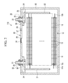
- FIG. 1 is a perspective view of a rechargeable battery according to a first exemplary embodiment of the present invention
- FIG. 2 is a cross-sectional view of FIG. 1 taken along the line II-II.
- a rechargeable battery 110 includes an electrode assembly 10 performing charging and discharging, a case 15 in which the electrode assembly 10 is installed, and a cap assembly 20 combined to an opening of the case 15.
- the rechargeable battery 110 is exemplarily described as a lithium ion battery.
- the present invention is not limited thereto. That is, the present invention may be applied to various types of batteries, such as a lithium polymer battery.
- the case 15 (in conjunction with the cap 20) forms the entire exterior of the rechargeable battery 110, and provides a space for installing the electrode assembly 10 therein.
- the case 15 is formed with a cuboid shape having an opening for receiving the cuboidal (i.e. cuboid-like shaped) electrode assembly 10.
- the case 15 may be formed with a pouch shape.
- case 15 may be formed with a metal such as aluminum, an aluminum alloy, and nickel-plated steel, or a pouch-shaped laminate film.
- the cap plate 28 is plate-shaped, and is combined to an opening of the case 15.
- a sealing cap 27 is provided at an electrolyte injection hole 29 of the cap plate 28.
- a vent plate 26 is provided at the cap plate 28 with a notch 26a, which is formed at a vent hole 24 and is capable of opening under a predetermined pressure.
- Positive and negative terminals 21 and 22 are electrically connected to the electrode assembly 10, and protrude to the outside of the case 15.
- the positive and the negative terminals 21 and 22 pass through the cap plate 28 and flanges are formed under the positive and negative terminals 21 and 22 while being supported at the bottom of the cap plate 28, while the outer circumference of the upper pillars thereof that are protruded to the outside of the cap plate 28 are screw-fastened. Furthermore, nuts 35 are coupled to the terminals 21 and 22 while supporting them from the top side.
- Upper and lower gaskets 38 and 39 are installed between the positive and negative terminals 21 and 22 and the cap plate 28 so as to seal and insulate the terminals 21 and 22 and the cap plate 28 from each other.
- the positive terminal 21 is electrically connected to the positive electrode 11 via a first lead tab 31, and the negative terminal 22 is electrically connected to the negative electrode 12 via a second lead tab 32.
- a lower insulating member 34 is disposed under the cap plate 28, and the bottom ends of the terminals 21 and 22 and the top ends of the lead tabs 31 and 32 are inserted into the lower insulating member 34.
- the first lead tab 31 electrically interconnects the positive terminal 21 and the positive electrode 11
- the second lead tab 32 electrically interconnects the negative terminal 22 and the negative electrode 12.
- the electrode assembly 10 is structured such that the positive and negative electrodes 11 and 12 are wound while interposing a separator 13 therebetween.
- the positive electrode 11, the negative electrode 12, and the separator 13 are band-shaped, and are elongated in a direction.
- the present invention is not limited thereto, and the electrode assembly 10 may be structured such that a plurality of positive and negative electrodes 11 and 12 are alternately deposited while interposing a separator 13 therebetween.
- the positive electrode 11 is structured such that a positive active material layer 112 is formed at both sides of a positive current collector 111.
- the positive current collector 111 is band-shaped and made of a material such as aluminum or stainless steel.
- the positive active material layer 112 is made of LiCoO 2 LiMnO 2 , LiFePO 4 , LiNiO 2 , LiMn 2 O 4 , or a carbon-based active material, or a trivalent active material, a conductive agent, and a binder.
- the negative electrode 12 is structured such that a negative active material layer 122 is formed at both sides of a negative current collector 121.
- the negative current collector 121 is band-shaped, and is made of a material such as copper, stainless steel, or aluminum.
- the negative active material layer 122 is made of Li 4 Ti 5 O 12 , a carbon-based material, a conductive agent, or a binder.
- a positive coating region 11 a where the positive active material layer 112 is formed and a positive uncoated region 11 b through which the positive current collector 111 is exposed are formed in the positive electrode 11.
- the positive active material layer 112 is not formed.
- the positive uncoated region 11 b extends along a length direction of the positive electrode 11 on one side of the electrode assembly 10.
- a negative coating region 12a where the negative active material layer 122 is formed, a first negative uncoated region 12b, and a second negative uncoated region 12c are formed in the negative electrode 12.
- the negative active material layer 122 is not formed and the negative current collector 121 is exposed through the first and second negative uncoated regions 12b and 12c.
- the first negative uncoated region 12b and the second negative uncoated region 12c extend along a length direction of the negative electrode 12 at respective sides thereof.
- the first negative uncoated region 12b is greater in width than the second negative uncoated region 12c.
- the first negative uncoated region 12b is formed at an opposite side to that where the positive uncoated region 11 b is formed in the electrode assembly 10, and the second negative uncoated region 12c is formed at the same side as that where the positive uncoated region 11 b is formed.
- the separator 13 has a structure in which a ceramic is included in a polymer porous membrane.
- the ceramic is embedded in the separator 13 according to the present exemplary embodiment. As described, when the ceramic is included in the separator 13, a short-circuit of the positive and negative electrodes due to melting of the separator 13 at a high temperature can be prevented, and excessive contraction of the separator 13 at a high temperature can be prevented.
- the contraction rate of the separator 13 at a high temperature can be controlled by changing the amount of the ceramic and the porosity.
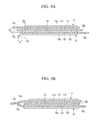
- FIG. 4A and FIG. 4B show partial cross-sectional views of the electrode assembly 10 according to the first exemplary embodiment of the present invention.
- a side of the negative active material layer 122 protrudes more to the outside than the positive active material layer 112.
- the positive uncoated region 11b protrudes more to the outside than the second negative uncoated region 12c
- the separator 13 protrudes more to the outside than the second uncoated region 12c and less than the positive uncoated region 11 b.
- the side of the separator is interposed between a side of the positive uncoated region 11 b and a side of the second negative uncoated region 12c.
- the separator 13 contracts when the temperature increases.
- the separator 13 continuously contracts until the temperature reaches 140°C, and does not further contract when the temperature is higher than 140°C.
- a lateral distance from the side of the separator 13 to the side of the second negative uncoated region 12c is D1
- a lateral distance from the side of the separator 13 to the negative active material layer 122 is D2
- a moving distance of a first side 13a of the separator 13 according to contraction at 140°C is SQ
- SQ satisfies Equation 1.
- the rechargeable battery 110 When the first side 13a moves or contracts less than D1, an internal short-circuit is not performed and thus the rechargeable battery 110 may be left at a high temperature so that the rechargeable battery 110 may explode or combust, and when the first side end 13a moves or contracts farther than D2, the negative active material layer 122 and the positive uncoated region 11 b are short-circuited so that the rechargeable battery 110 may explode or combust.
- D1 is 0.5mm to 10mm
- D3 which is a distance between the positive uncoated region 11 b and the second negative uncoated region 12c, is 0.05mm to 0.5mm.
- D2 satisfies D3 ⁇ D2 ⁇ 30mm, and the length that the negative active material layer 122 is more protruded than the positive active material layer 112 is 0.05mm to 0.5mm.
- SR1 satisfies Equation 2. 2 * D ⁇ 1 / SW ⁇ 1 * 100 % ⁇ SR ⁇ 1 % ⁇ 2 * D ⁇ 2 / SW ⁇ 1 * 100 %
- the first side 13a and a second side 13b of the separator 13 move towards the center of the separator 13 so that the first side 13a of the separator 13 can be located further inside than the second negative uncoated region 12c only when the separator 13 contracts more than twice D1.
- the contraction ratio SR1 of the separator 13 is less than (2*D1/W1)*100, an internal short-circuit is not induced and thus the rechargeable battery 110 may be left at a high temperature
- the contraction ratio SR1 is greater than SR1 (2*D2/SW1)*00, the negative active material layer 122 and the positive uncoated region 11 b may be short-circuited.
- FIG. 5 is a partial cross-sectional view of an electrode assembly according to a second exemplary embodiment of the present invention.
- an electrode assembly 50 includes a positive electrode 51, a negative electrode 52, and a separator 53 disposed between the positive electrode 51 and the negative electrode 52.
- the positive electrode 51 includes a positive current collector 511 and a positive active material layer 512 formed at both sides of the positive current collector 511.
- a positive coated region 51 a where the positive active material layer 512 is formed and a positive uncoated region 51 b where the positive current collector 511 is exposed are formed in the positive electrode 51.
- the positive uncoated region 51 b the positive active material layer 512 is not formed.
- the negative electrode 52 includes a negative current collector 521 and a negative active material layer 522 formed at both sides of the negative current collector 521.
- a negative coated region 52a where the negative active material layer 522 is formed and a first negative uncoated region (not shown) and a second negative uncoated region 52b through which the negative current collector 521 is exposed are formed in the negative electrode 52. In the first and second negative uncoated regions 52b, the negative active material layer 522 is not formed.
- the separator 53 includes a porous member 532 and a ceramic layer 531 disposed at both sides of the porous member 532.
- the separator 53 is manufactured through a wet etching process during which width directional contraction occurs at a high temperature.
- the contraction ratio of the separator 53 at a high temperature can be controlled by changing the thickness of the ceramic layer.
- the electrode assembly 50 is formed of a structure in which the positive electrode 51, the negative electrode 52, and the separator 53 that are formed with a band shape are stacked.
- the positive uncoated region 51 b is formed at one side of the electrode assembly 50, and the first negative uncoated region (not shown) is formed at the other side thereof.
- the second negative uncoated region 52b is formed at the side where the positive uncoated region 51 b is formed.
- Both sides of the negative active material layer 522 are more protruded to the outside than the positive active material layer 512.
- the positive uncoated region 51 b protrudes more to the outside than the second negative uncoated region 52b
- the separator 53 protrudes to the outside more than the second negative uncoated region 52b and less than the positive uncoated region 51 b. Therefore, one side 53a of the separator 53 is placed between a side of the positive uncoated region 51 b and a side of the second uncoated region 52b.
- the separator 53 contracts in a high temperature environment, the one side 53a of the separator 13 moves further towards the inside than the side of the second negative uncoated region 52b, and accordingly the second negative uncoated region 52b and the positive uncoated region 51b are short-circuited, thereby preventing excessive overheating.
- the ceramic layer 531 is coated over the separator 53, the separator 53 can be prevented from being melted.
- FIG. 6 is a cross-sectional view of an electrode assembly according to a third exemplary embodiment of the present invention.
- an electrode assembly 60 includes a positive electrode 61, a negative electrode 62, and a separator 63 disposed between the positive electrode 61 and the negative electrode 62.
- the positive electrode 61 includes a positive current collector 611 and a positive active material layer 612 formed at both sides of the positive current collector 611.
- a positive coated region 61 a where the positive active material layer 612 is formed is formed in the positive electrode 61, and a positive uncoated region 61 b where the positive current collector 611 is exposed is formed therein. In the positive uncoated region 61 b, the positive active material layer 612 is not formed.
- the negative electrode 62 includes a negative current collector 621, a negative active material layer 622 coated on the negative current collector 621, and a ceramic layer 623 coated on the negative active material layer 622.
- the negative current collector 621 and the negative active material layer 622 are structured the same as those of the first exemplary embodiment.
- the ceramic layer 623 is coated on the negative active material layer 622 while having an area corresponding to the negative active material layer 622.
- a negative coated region 62a where the negative active material layer 622 is formed and a first negative uncoated region (not shown) and a second negative uncoated region 62b through which the negative current collector 621 is exposed are formed in the negative electrode 62.
- the negative active material layer 622 is not formed.
- the first negative uncoated region (not shown) is greater than the second negative uncoated region 62b in width.
- the electrode assembly 60 has a structure in which the positive electrode 61, the negative electrode 62, and the separator 63 that have a band shape are stacked and then wound.
- the positive uncoated region 61 b is formed at one side in a width direction of the electrode assembly 60, and the first negative uncoated region (not shown) is formed at the other side in the width direction of the electrode assembly 60.
- the second negative uncoated region 62b is formed at the side where the positive uncoated region 61 b is formed.
- Both sides of the negative active material layer 622 are more protruded to the outside than the positive active material layer 612.
- the positive uncoated region 61b is more protruded than the second negative uncoated region 62b
- the separator 63 is protruded to the outside more than the second negative uncoated region 62b and less than the positive uncoated region 61b. Accordingly, one side 63a of the separator 63 is placed between a side of the positive uncoated region 61 b and a side of the second negative uncoated region 62b.
- the ceramic layer 623 when the ceramic layer 623 is formed on the negative active material layer 622, a short-circuit between the negative active material layer 622 and the positive active material layer 612 and a short-circuit between the negative active material 622 and the positive uncoated region 61 b can be prevented.
- the separator 63 contracts at a high temperature, the second negative uncoated region 62b and the positive uncoated region 61b are short-circuited, thereby preventing excessive overheating.
Landscapes
- Chemical & Material Sciences (AREA)
- Chemical Kinetics & Catalysis (AREA)
- Electrochemistry (AREA)
- General Chemical & Material Sciences (AREA)
- Engineering & Computer Science (AREA)
- Manufacturing & Machinery (AREA)
- Secondary Cells (AREA)
- Battery Electrode And Active Subsutance (AREA)
- Connection Of Batteries Or Terminals (AREA)
- Sealing Battery Cases Or Jackets (AREA)
- Cell Separators (AREA)
Abstract
Description
- The present invention relates to an electrode assembly and a rechargeable battery using the same. More particularly, the present invention relates to an electrode assembly having an improved structure and a rechargeable battery using the same.
- Unlike a primary battery that cannot be recharged, a rechargeable battery can be repeatedly charged and discharged. Low-capacity rechargeable batteries are used for portable compact electronic apparatuses such as mobile phones, notebook computers, and camcorders, and high-capacity rechargeable batteries are widely used as a power source for driving a motor of a hybrid vehicle, etc.
- A high-power rechargeable battery using a non-aqueous electrolyte with high energy density has been recently developed. For example, the high-power rechargeable battery is constructed with a high-capacity rechargeable battery having a plurality of rechargeable cells coupled to each other in series such that it can be used as the power supply for driving motors in electric vehicles requiring high power.
- In addition, one high-capacity rechargeable battery is commonly formed with a plurality of rechargeable cells coupled to each other in series. The rechargeable battery may have a cylindrical shape, a prismatic shape, a pouch shape, etc.
- An electrode assembly includes a positive electrode, a negative electrode, and a separator disposed between the positive and negative electrodes. Here, the separator separates the positive electrode and the negative electrode to prevent a short-circuit therebetween, and absorbs electrolyte required for a battery reaction to maintain high ion conductivity.
- When internal temperature of the rechargeable battery increases due to overcharge, the separator may contract or be melted so that a short-circuit may occur between the positive electrode and the negative electrode. When the short-circuit occurs, the internal temperature of the rechargeable battery is rapidly increased so that the rechargeable battery may combust or explode.
- The short-circuit includes a short-circuit between a positive active material layer and a negative active material layer, a short-circuit between a positive active material layer and a negative current collector, a short-circuit between a negative active material layer and a positive current collector, and a short-circuit between a positive current collector and a negative current collector. Considering a temperature increase during the short-circuit, it has been determined that a short-circuit between the negative active material layer and the positive current collector is the most dangerous, and a short-circuit between the positive current collector and the negative current collector is the least dangerous.
- However, when the positive uncoated region and the negative uncoated region are respectively formed at opposite sides of the electrode assembly, the positive uncoated region and the negative active material layer may possibly be short-circuited rather than the positive and negative current collectors being short-circuited. As described, when the positive uncoated region and the negative active material layer are short-circuited, excessive heat is generated so that the rechargeable battery may combust or explode.
- The above information disclosed in this Background section is only for enhancement of understanding of the background of the invention and therefore it may contain information that does not form the prior art that is already known to a person of ordinary skill in the art.
- The present invention has been made in an effort to provide an electrode assembly and a rechargeable battery with improved safety.
- An electrode assembly according to an exemplary embodiment of the present invention includes a positive electrode, a negative electrode, and a separator. A positive uncoated region where a positive active material layer is not formed is formed at one side of the positive electrode. A first negative uncoated region where a negative active material layer is not formed is formed at the other side of the negative electrode, and a second negative uncoated region is formed at one side thereof. The separator is disposed between the positive and negative electrodes, and is more protruded to the positive uncoated region than the second negative uncoated region.
- A rechargeable battery according to an exemplary embodiment of the present invention includes an electrode assembly performing charging and discharging, a case in which the electrode assembly is installed, and a terminal electrically connected to the electrode assembly and protruded to the outside of the case. The electrode assembly includes a positive electrode, a negative electrode, and a separator. A positive uncoated region where a positive active material layer is not formed is formed at one side of the positive electrode. A first negative uncoated region where a negative active material layer is not formed is formed at the other side of the negative electrode, and a second negative uncoated is formed at the one side thereof. The separator is disposed between the positive and negative electrodes, and is more protruded to the positive uncoated region than the second negative uncoated region.
- According to the exemplary embodiment of the present invention, a ceramic layer is formed on the separator or the negative electrode so that a short-circuit between the positive active material layer and the negative active material layer and a short-circuit between the positive or negative active material layer and the current collector can be prevented. Furthermore, a short-circuit between the positive current collector and the negative current collector is performed at a high temperature so as to prevent the internal temperature of the rechargeable battery from being excessively increased.
- Preferably, the positive current collector and the negative current collector are made of a material having an electrical conductivity of more than 106 [S m-1]. More preferably, the positive current collector and the negative current collector are made of a material having an electrical conductivity of more than 107 [S m-1]. More preferably, the positive current collector and the negative current collector are made of a metal.
- Preferably, the active material layers comprise a compound containing lithium.
-
-
FIG. 1 is a perspective view of a rechargeable battery according to a first exemplary embodiment of the present invention. -
FIG. 2 is a cross-sectional view ofFIG. 1 , taken along the line II-II. -
FIG. 3 is a perspective view of an electrode assembly according to the first exemplary embodiment of the present invention. -
FIG. 4A and FIG. 4B are partial cross-sectional views of the electrode assembly according to the first exemplary embodiment of the present invention. -
FIG. 5 is a partial cross-sectional view of an electrode assembly according to a second exemplary embodiment of the present invention. -
FIG. 6 is a partial cross-sectional view of an electrode assembly according to a third exemplary embodiment of the present invention. -
- 110:
rechargeable battery - 11, 51, 61: positive electrode
- 111, 511, 611: positive current collector
- 112, 512, 612: positive active material layer
- 11a, 51 a, 61 a: positive coating region
- 11 b, 51b, 61b: positive uncoated region
- 12, 52, 62: negative electrode
- 121, 521, 621: negative current collector
- 122, 522, 622: negative active material layer
- 12a, 52a, 62a: negative coating region
- 12b: first negative uncoated region
- 12c, 52b, 62b: second negative uncoated region
- 13, 53, 63: separator
- 15: case 20: cap assembly
- 21: positive terminal 22: negative terminal
- 531, 623: ceramic layer 532: porous member
- The present invention will be described more fully hereinafter with reference to the accompanying drawings, in which exemplary embodiments of the present invention are shown. As those skilled in the art would realize, the described embodiments may be modified in various different ways, all without departing from the scope of the present invention. Like reference numerals designate like elements throughout the specification and drawings.
-
FIG. 1 is a perspective view of a rechargeable battery according to a first exemplary embodiment of the present invention, andFIG. 2 is a cross-sectional view ofFIG. 1 taken along the line II-II. - Referring to
FIG. 1 andFIG. 2 , arechargeable battery 110 includes anelectrode assembly 10 performing charging and discharging, acase 15 in which theelectrode assembly 10 is installed, and acap assembly 20 combined to an opening of thecase 15. - In the first exemplary embodiment, the
rechargeable battery 110 is exemplarily described as a lithium ion battery. However, the present invention is not limited thereto. That is, the present invention may be applied to various types of batteries, such as a lithium polymer battery. - The case 15 (in conjunction with the cap 20) forms the entire exterior of the
rechargeable battery 110, and provides a space for installing theelectrode assembly 10 therein. For example, thecase 15 is formed with a cuboid shape having an opening for receiving the cuboidal (i.e. cuboid-like shaped)electrode assembly 10. Thecase 15 may be formed with a pouch shape. - Furthermore, the
case 15 may be formed with a metal such as aluminum, an aluminum alloy, and nickel-plated steel, or a pouch-shaped laminate film. - The
cap plate 28 is plate-shaped, and is combined to an opening of thecase 15. A sealingcap 27 is provided at anelectrolyte injection hole 29 of thecap plate 28. Furthermore, avent plate 26 is provided at thecap plate 28 with anotch 26a, which is formed at avent hole 24 and is capable of opening under a predetermined pressure. - Positive and
negative terminals electrode assembly 10, and protrude to the outside of thecase 15. - The positive and the
negative terminals cap plate 28 and flanges are formed under the positive andnegative terminals cap plate 28, while the outer circumference of the upper pillars thereof that are protruded to the outside of thecap plate 28 are screw-fastened. Furthermore, nuts 35 are coupled to theterminals - Upper and
lower gaskets negative terminals cap plate 28 so as to seal and insulate theterminals cap plate 28 from each other. - The
positive terminal 21 is electrically connected to thepositive electrode 11 via afirst lead tab 31, and thenegative terminal 22 is electrically connected to thenegative electrode 12 via asecond lead tab 32. - Meanwhile, a lower insulating
member 34 is disposed under thecap plate 28, and the bottom ends of theterminals lead tabs member 34. - With this structure, the
first lead tab 31 electrically interconnects thepositive terminal 21 and thepositive electrode 11, and thesecond lead tab 32 electrically interconnects thenegative terminal 22 and thenegative electrode 12. - As shown in
FIG. 3 , theelectrode assembly 10 is structured such that the positive andnegative electrodes separator 13 therebetween. Thepositive electrode 11, thenegative electrode 12, and theseparator 13 are band-shaped, and are elongated in a direction. However, the present invention is not limited thereto, and theelectrode assembly 10 may be structured such that a plurality of positive andnegative electrodes separator 13 therebetween. - As shown in
FIG. 4A , thepositive electrode 11 is structured such that a positiveactive material layer 112 is formed at both sides of a positivecurrent collector 111. The positivecurrent collector 111 is band-shaped and made of a material such as aluminum or stainless steel. The positiveactive material layer 112 is made of LiCoO2 LiMnO2, LiFePO4, LiNiO2, LiMn2O4, or a carbon-based active material, or a trivalent active material, a conductive agent, and a binder. - The
negative electrode 12 is structured such that a negativeactive material layer 122 is formed at both sides of a negativecurrent collector 121. The negativecurrent collector 121 is band-shaped, and is made of a material such as copper, stainless steel, or aluminum. The negativeactive material layer 122 is made of Li4Ti5O12, a carbon-based material, a conductive agent, or a binder. - As shown in
FIG. 3 , apositive coating region 11 a where the positiveactive material layer 112 is formed and a positiveuncoated region 11 b through which the positivecurrent collector 111 is exposed are formed in thepositive electrode 11. In the positiveuncoated region 11 b, the positiveactive material layer 112 is not formed. The positiveuncoated region 11 b extends along a length direction of thepositive electrode 11 on one side of theelectrode assembly 10. - A
negative coating region 12a where the negativeactive material layer 122 is formed, a first negativeuncoated region 12b, and a second negativeuncoated region 12c are formed in thenegative electrode 12. In the first and second negativeuncoated regions active material layer 122 is not formed and the negativecurrent collector 121 is exposed through the first and second negativeuncoated regions uncoated region 12b and the second negativeuncoated region 12c extend along a length direction of thenegative electrode 12 at respective sides thereof. The first negativeuncoated region 12b is greater in width than the second negativeuncoated region 12c. - The first negative
uncoated region 12b is formed at an opposite side to that where the positiveuncoated region 11 b is formed in theelectrode assembly 10, and the second negativeuncoated region 12c is formed at the same side as that where the positiveuncoated region 11 b is formed. - The
separator 13 has a structure in which a ceramic is included in a polymer porous membrane. The ceramic is embedded in theseparator 13 according to the present exemplary embodiment. As described, when the ceramic is included in theseparator 13, a short-circuit of the positive and negative electrodes due to melting of theseparator 13 at a high temperature can be prevented, and excessive contraction of theseparator 13 at a high temperature can be prevented. - In this case, the contraction rate of the
separator 13 at a high temperature can be controlled by changing the amount of the ceramic and the porosity. -
FIG. 4A and FIG. 4B show partial cross-sectional views of theelectrode assembly 10 according to the first exemplary embodiment of the present invention. - Referring to
FIG. 4A and FIG. 4B , theelectrode assembly 10 will be described in further detail. - When the
electrode assembly 10 is initially manufactured, a side of the negativeactive material layer 122 protrudes more to the outside than the positiveactive material layer 112. In addition, the positiveuncoated region 11b protrudes more to the outside than the second negativeuncoated region 12c, and theseparator 13 protrudes more to the outside than the seconduncoated region 12c and less than the positiveuncoated region 11 b. Accordingly, the side of the separator is interposed between a side of the positiveuncoated region 11 b and a side of the second negativeuncoated region 12c. - The
separator 13 contracts when the temperature increases. Theseparator 13 continuously contracts until the temperature reaches 140°C, and does not further contract when the temperature is higher than 140°C. - If a lateral distance from the side of the
separator 13 to the side of the second negativeuncoated region 12c is D1, a lateral distance from the side of theseparator 13 to the negativeactive material layer 122 is D2, and a moving distance of afirst side 13a of theseparator 13 according to contraction at 140°C is SQ, SQ satisfies Equation 1.
- When the
first side 13a moves or contracts less than D1, an internal short-circuit is not performed and thus therechargeable battery 110 may be left at a high temperature so that therechargeable battery 110 may explode or combust, and when thefirst side end 13a moves or contracts farther than D2, the negativeactive material layer 122 and the positiveuncoated region 11 b are short-circuited so that therechargeable battery 110 may explode or combust. - Here, D1 is 0.5mm to 10mm, and D3, which is a distance between the positive
uncoated region 11 b and the second negativeuncoated region 12c, is 0.05mm to 0.5mm. - D2 satisfies D3≤D2≤30mm, and the length that the negative
active material layer 122 is more protruded than the positiveactive material layer 112 is 0.05mm to 0.5mm. - In addition, if an initial width of the
separator 13 is SW1 and a ratio of contraction in width of theseparator 13 until the temperature reaches 140°C is SR1, SR1 satisfies Equation 2.
- When the
separator 13 contracts, thefirst side 13a and asecond side 13b of theseparator 13 move towards the center of theseparator 13 so that thefirst side 13a of theseparator 13 can be located further inside than the second negativeuncoated region 12c only when theseparator 13 contracts more than twice D1. Accordingly, when the contraction ratio SR1 of theseparator 13 is less than (2*D1/W1)*100, an internal short-circuit is not induced and thus therechargeable battery 110 may be left at a high temperature, and when the contraction ratio SR1 is greater than SR1 (2*D2/SW1)*00, the negativeactive material layer 122 and the positiveuncoated region 11 b may be short-circuited. - As shown in
FIG. 4B , when theseparator 13 contracts within the above-stated range, the positiveuncoated region 11 b and the second negativeuncoated region 12c are short-circuited so that an excessive increase of temperature of theelectrode assembly 10 can be prevented. -
FIG. 5 is a partial cross-sectional view of an electrode assembly according to a second exemplary embodiment of the present invention. - Referring to
FIG. 5 , anelectrode assembly 50 according to the present exemplary embodiment includes apositive electrode 51, anegative electrode 52, and aseparator 53 disposed between thepositive electrode 51 and thenegative electrode 52. - The
positive electrode 51 includes a positivecurrent collector 511 and a positiveactive material layer 512 formed at both sides of the positivecurrent collector 511. In addition, a positivecoated region 51 a where the positiveactive material layer 512 is formed and a positiveuncoated region 51 b where the positivecurrent collector 511 is exposed are formed in thepositive electrode 51. In the positiveuncoated region 51 b, the positiveactive material layer 512 is not formed. - The
negative electrode 52 includes a negativecurrent collector 521 and a negativeactive material layer 522 formed at both sides of the negativecurrent collector 521. In addition, a negativecoated region 52a where the negativeactive material layer 522 is formed and a first negative uncoated region (not shown) and a second negativeuncoated region 52b through which the negativecurrent collector 521 is exposed are formed in thenegative electrode 52. In the first and second negativeuncoated regions 52b, the negativeactive material layer 522 is not formed. - The
separator 53 includes aporous member 532 and aceramic layer 531 disposed at both sides of theporous member 532. In this case, theseparator 53 is manufactured through a wet etching process during which width directional contraction occurs at a high temperature. The contraction ratio of theseparator 53 at a high temperature can be controlled by changing the thickness of the ceramic layer. - The
electrode assembly 50 is formed of a structure in which thepositive electrode 51, thenegative electrode 52, and theseparator 53 that are formed with a band shape are stacked. The positiveuncoated region 51 b is formed at one side of theelectrode assembly 50, and the first negative uncoated region (not shown) is formed at the other side thereof. In addition, the second negativeuncoated region 52b is formed at the side where the positiveuncoated region 51 b is formed. - Both sides of the negative
active material layer 522 are more protruded to the outside than the positiveactive material layer 512. In addition, the positiveuncoated region 51 b protrudes more to the outside than the second negativeuncoated region 52b, and theseparator 53 protrudes to the outside more than the second negativeuncoated region 52b and less than the positiveuncoated region 51 b. Therefore, oneside 53a of theseparator 53 is placed between a side of the positiveuncoated region 51 b and a side of the seconduncoated region 52b. - When the
separator 53 contracts in a high temperature environment, the oneside 53a of theseparator 13 moves further towards the inside than the side of the second negativeuncoated region 52b, and accordingly the second negativeuncoated region 52b and the positiveuncoated region 51b are short-circuited, thereby preventing excessive overheating. In addition, since theceramic layer 531 is coated over theseparator 53, theseparator 53 can be prevented from being melted. -
FIG. 6 is a cross-sectional view of an electrode assembly according to a third exemplary embodiment of the present invention. - Referring to
FIG. 6 , anelectrode assembly 60 according to the present exemplary embodiment includes apositive electrode 61, anegative electrode 62, and aseparator 63 disposed between thepositive electrode 61 and thenegative electrode 62. - The
positive electrode 61 includes a positivecurrent collector 611 and a positiveactive material layer 612 formed at both sides of the positivecurrent collector 611. In addition, a positivecoated region 61 a where the positiveactive material layer 612 is formed is formed in thepositive electrode 61, and a positiveuncoated region 61 b where the positivecurrent collector 611 is exposed is formed therein. In the positiveuncoated region 61 b, the positiveactive material layer 612 is not formed. - The
negative electrode 62 according to the present exemplary embodiment includes a negativecurrent collector 621, a negativeactive material layer 622 coated on the negativecurrent collector 621, and aceramic layer 623 coated on the negativeactive material layer 622. The negativecurrent collector 621 and the negativeactive material layer 622 are structured the same as those of the first exemplary embodiment. Theceramic layer 623 is coated on the negativeactive material layer 622 while having an area corresponding to the negativeactive material layer 622. - In addition, a negative
coated region 62a where the negativeactive material layer 622 is formed and a first negative uncoated region (not shown) and a second negativeuncoated region 62b through which the negativecurrent collector 621 is exposed are formed in thenegative electrode 62. In the first and second negativeuncoated regions 62b, the negativeactive material layer 622 is not formed. The first negative uncoated region (not shown) is greater than the second negativeuncoated region 62b in width. - The
electrode assembly 60 has a structure in which thepositive electrode 61, thenegative electrode 62, and theseparator 63 that have a band shape are stacked and then wound. The positiveuncoated region 61 b is formed at one side in a width direction of theelectrode assembly 60, and the first negative uncoated region (not shown) is formed at the other side in the width direction of theelectrode assembly 60. In addition, the second negativeuncoated region 62b is formed at the side where the positiveuncoated region 61 b is formed. - Both sides of the negative
active material layer 622 are more protruded to the outside than the positiveactive material layer 612. In addition, the positiveuncoated region 61b is more protruded than the second negativeuncoated region 62b, and theseparator 63 is protruded to the outside more than the second negativeuncoated region 62b and less than the positiveuncoated region 61b. Accordingly, oneside 63a of theseparator 63 is placed between a side of the positiveuncoated region 61 b and a side of the second negativeuncoated region 62b. - In the present exemplary embodiment, when the
ceramic layer 623 is formed on the negativeactive material layer 622, a short-circuit between the negativeactive material layer 622 and the positiveactive material layer 612 and a short-circuit between the negativeactive material 622 and the positiveuncoated region 61 b can be prevented. In addition, when theseparator 63 contracts at a high temperature, the second negativeuncoated region 62b and the positiveuncoated region 61b are short-circuited, thereby preventing excessive overheating. - While this invention has been described in connection with what is presently considered to be practical exemplary embodiments, it is to be understood that the invention is not limited to the disclosed embodiments, but, on the contrary, is intended to cover various modifications and equivalent arrangements included within the scope of the appended claims.
Claims (15)
- An electrode assembly (10, 50, 60) comprising:a first electrode (11, 51, 61),a second electrode (12, 52, 62), anda separator (13, 53, 63) disposed between the first electrode (11, 51, 61) and the second electrode (12, 52, 62),wherein the first electrode (11, 51, 61) comprises a first current collector (111,511,611), the first current collector (111,511,611) having a coating region (11a, 51a, 61a) in which an active material layer (112, 512, 612) is formed on the first current collector (111, 511, 611) and at least one uncoated region (11b, 51b, 61 b) in which the first current collector (111, 511, 611) is exposed, the at least one uncoated region (11b, 51b, 61b) being located at a first side of the electrode assembly (10, 50, 60), andwherein the second electrode (12, 52, 62) comprises a second current collector (121, 521, 621), the second current collector (121, 521, 621) having a coating region (12a, 52a, 62a) in which an active material layer (122, 522, 622) is formed on the second current collector (121, 521, 621) and at least one uncoated region (12c, 52b, 62b) in which the second current collector (121, 521, 621) is exposed, the at least one uncoated region (12c, 52b, 62b) being located at the first side of the electrode assembly (10, 50, 60),characterized in thata side portion (13a, 53a, 63a) of the separator (13, 53, 63) extends farther to the first side of the electrode assembly (10, 50, 60) along a first axis than a side portion of the uncoated region (12c, 52b, 62b) of the second electrode (12, 52, 62) at a temperature range of 20° to 60° C,wherein the first axis extends parallel to the main surfaces of the electrodes (11, 51, 61, 12, 52, 62) and perpendicular to edges of the electrodes (11, 51, 61, 12, 52, 62) located at the first side of the electrode assembly (10, 50, 60).
- The electrode assembly (10, 50, 60) of claim 1, wherein the second electrode comprises an additional uncoated region (12b) at a second side.
- The electrode assembly (10, 50, 60) of claim 2, wherein the extension of the uncoated region (12c, 52b, 62b) along the first axis at the first side is smaller than the extension of the uncoated region (12b) at the second side.
- The electrode assembly (10, 50, 60) according to any of claims 2 and 3, wherein the first electrode (11) comprises an additional uncoated region at a second side and the side portion of the separator (13, 53, 63) extends farther to the second side of the electrode assembly (10, 50, 60) along a first axis than a side portion of the uncoated region of the first electrode at a temperature range of 20°- 60° C.
- The electrode assembly (10, 50, 60) according to any one of the preceding claims, wherein the following condition (1) is met:

wherein SQ is a distance extending along the first axis between a location of a side portion (13a, 53a, 63a) of the separator (13, 53, 63) extending to the first side at a temperature of 20° to 60° C and a location of the side portion (13a, 53a, 63a) of the separator (13, 53, 63) at a temperature of over 140° C, D1 is a lateral distance along the first axis from the side portion (13a, 53a, 63a) of the separator (13, 53, 63) to a side portion of the uncoated region (12c), and D2 is a distance along the first axis between the side portion (13a, 53a, 63a) of the separator (13, 53, 63) to a side portion of the active material layer (122, 522, 622) of the second electrode at a temperature of 20° C to 60° C. - The electrode assembly (10, 50, 60) according to any one of the preceding claims, wherein the following condition (2) is met:

wherein D3 is a minimum distance between a uncoated region (11 b, 51 b, 61 b) of the first electrode (11) and an adjacent uncoated region (12c, 52b, 62b) of the second electrode (12) along a second axis which extends perpendicular to the first axis. - The electrode assembly (10, 50, 60) according to any one of claims 3 and 4, wherein D1 ranges between 0.5 and 10.0 mm at a temperature of 20° to 60° C, and D3 ranges between 0.05 and 0.5 mm at a temperature of 20° to 60° C.
- The electrode assembly (10, 50, 60) according to any one of the preceding claims, wherein a side portion of the active material layer (122, 522, 622) of the second electrode (12) extends farther along the first axis to the first side of the electrode assembly (10, 50, 60) than a side portion of the active material layer (112, 512, 612) of the first electrode (11) and a distance (D4) along the first axis between the side portion of the active material layer (122, 522, 622) of the second electrode (12) and the side portion of the active material layer (112, 512, 612) of the first electrode (11) ranges between 0.05 and 0.5 mm.
- The electrode assembly (10, 50, 60) according to any one of the preceding claims, wherein a side portion of the uncoated region (11 b, 51 b, 61 b) of the first electrode (11) extends farther to the first side of the electrode assembly (10, 50, 60) than a side portion (13a, 53a, 63a) of the separator (13, 53, 63).
- The electrode assembly (10, 50, 60) according to any one of the preceding claims, wherein the separator (53) comprises a porous member (532) and a ceramic layer (531) disposed at both sides of the porous member (532).
- The electrode assembly (10, 50, 60) according to any one of the preceding claims, wherein a ceramic layer (623) is formed on the active material layer (622) of the second electrode (62) and/or a ceramic layer is formed on the active material layer of the first electrode (61).
- The electrode assembly (10, 50, 60) according to any one of the preceding claims, wherein the first electrode (11, 51, 61) and the second electrode (12, 52, 62) are wound while interposing at least one separator (13, 53, 63) therebetween, wherein the first electrode (11, 51, 61), the second electrode (12, 52, 62) and the least one separator (13, 53, 63) are band-shaped and elongated in a common direction.
- The electrode assembly (10, 50, 60) of claim 11, comprising a plurality of first electrodes (11, 51, 61) and second electrodes (12, 52, 62) which are alternately stacked while interposing at least one separator (13, 53, 63) therebetween.
- A rechargeable battery (110) comprising an electrode assembly (10, 50, 60) according to any one of the preceding claims adapted to perform charging and discharging, a case (15) in which the electrode assembly (10, 50, 60) is installed, a first terminal (21) a second terminal (22) electrically connected to the electrode assembly (10, 50, 60) and protruded to the outside of the case (15).
- The rechargeable battery (110) of claim 14, wherein the rechargeable battery (110) is a secondary lithium-ion battery and/or wherein the rechargeable battery (110) further comprises a first lead tab (31) which is electrically connected to the first terminal (21) and to the firstelectrode (11) in a portion located at the first side of the electrode assembly (10, 50, 60), and a second lead tab (32) which is electrically connected to the second terminal (22) and to the second electrode (12) in a portion located at a second side opposing the first side of the electrode assembly (10, 50, 60).
Applications Claiming Priority (2)
| Application Number | Priority Date | Filing Date | Title |
|---|---|---|---|
| US25623009P | 2009-10-29 | 2009-10-29 | |
| US12/713,144 US8574752B2 (en) | 2009-10-29 | 2010-02-25 | Electrode assembly and rechargeable battery using the same |
Publications (2)
| Publication Number | Publication Date |
|---|---|
| EP2325925A1 true EP2325925A1 (en) | 2011-05-25 |
| EP2325925B1 EP2325925B1 (en) | 2012-12-19 |
Family
ID=43532974
Family Applications (1)
| Application Number | Title | Priority Date | Filing Date |
|---|---|---|---|
| EP10188980A Active EP2325925B1 (en) | 2009-10-29 | 2010-10-27 | Electrode assembly and rechargeable battery using the same |
Country Status (4)
| Country | Link |
|---|---|
| US (1) | US8574752B2 (en) |
| EP (1) | EP2325925B1 (en) |
| JP (1) | JP5400013B2 (en) |
| CN (1) | CN102054958B (en) |
Cited By (2)
| Publication number | Priority date | Publication date | Assignee | Title |
|---|---|---|---|---|
| EP2546905A1 (en) * | 2011-07-12 | 2013-01-16 | Samsung SDI Co., Ltd. | Secondary battery |
| WO2014024019A1 (en) * | 2012-08-08 | 2014-02-13 | Toyota Jidosha Kabushiki Kaisha | Method of manufacturing non-aqueous electrolyte secondary battery and non-aqueous electrolyte secondary battery |
Families Citing this family (12)
| Publication number | Priority date | Publication date | Assignee | Title |
|---|---|---|---|---|
| KR101135492B1 (en) * | 2010-01-20 | 2012-04-13 | 삼성에스디아이 주식회사 | Electrode assembly, and rechargeable battery using thereof |
| JP5087110B2 (en) * | 2010-06-21 | 2012-11-28 | 日立ビークルエナジー株式会社 | Secondary battery |
| EP2469620B1 (en) * | 2010-12-24 | 2013-08-14 | swissbatt AG | Battery |
| JP2014035923A (en) * | 2012-08-09 | 2014-02-24 | Sanyo Electric Co Ltd | Non-aqueous electrolyte secondary battery |
| KR102612062B1 (en) * | 2016-06-24 | 2023-12-07 | 삼성에스디아이 주식회사 | Rechargeable battery |
| KR102273100B1 (en) | 2017-11-01 | 2021-07-02 | 주식회사 엘지에너지솔루션 | Electrode assembly and method of stabilizing secondary battery |
| CN111697199B (en) * | 2019-03-12 | 2024-09-10 | 宁德新能源科技有限公司 | Pole piece and electrode assembly using the same |
| CN112133861B (en) * | 2020-10-12 | 2021-05-11 | 东莞市云帆电子科技有限公司 | A power lithium battery module combination structure |
| CN114520303B (en) * | 2020-11-19 | 2024-10-18 | 宁德新能源科技有限公司 | Electrochemical device and electronic device |
| JP7265580B2 (en) * | 2021-04-26 | 2023-04-26 | プライムプラネットエナジー&ソリューションズ株式会社 | Non-aqueous electrolyte secondary battery |
| JP2025534676A (en) * | 2022-10-28 | 2025-10-17 | エルジー エナジー ソリューション リミテッド | Electrode assembly for secondary battery and cylindrical secondary battery including the same |
| EP4632867A4 (en) * | 2022-12-23 | 2026-04-22 | Lg Energy Solution Ltd | ELECTRODE ARRANGEMENT, CYLINDRICAL BATTERY CELL AND BATTERY PACK SO THAT |
Citations (4)
| Publication number | Priority date | Publication date | Assignee | Title |
|---|---|---|---|---|
| US5925482A (en) * | 1995-01-27 | 1999-07-20 | Asahi Kasei Kogyo Kabushiki Kaisha | Non-aqueous battery |
| US20070292765A1 (en) * | 2004-12-10 | 2007-12-20 | Kaoru Inoue | Lithium Ion Secondary Battery And Method For Producing Negative Electrode Therefor |
| WO2008013853A2 (en) * | 2006-07-26 | 2008-01-31 | Eveready Battery Company, Inc. | Lithium-iron disulfide cylindrical cell with modified positive electrode |
| EP1998401A2 (en) * | 2007-05-25 | 2008-12-03 | Samsung SDI Co., Ltd. | Electrode assembley and secondary battery using the same |
Family Cites Families (19)
| Publication number | Priority date | Publication date | Assignee | Title |
|---|---|---|---|---|
| JPH09306471A (en) | 1996-05-16 | 1997-11-28 | Japan Storage Battery Co Ltd | Non-aqueous electrolyte secondary battery and method of manufacturing the same |
| CN1172400C (en) | 1999-08-10 | 2004-10-20 | 三洋电机株式会社 | Nonaqueous electrolyte secondary battery and method for manufacturing same |
| JP3920549B2 (en) | 2000-09-26 | 2007-05-30 | 三洋電機株式会社 | Non-aqueous electrolyte secondary battery |
| KR100449757B1 (en) | 2001-11-23 | 2004-09-22 | 삼성에스디아이 주식회사 | Battery unit and secondary battery applying the such |
| JP4201619B2 (en) | 2003-02-26 | 2008-12-24 | 三洋電機株式会社 | Nonaqueous electrolyte secondary battery and method for producing electrode used therefor |
| JP2004335335A (en) | 2003-05-09 | 2004-11-25 | Mitsubishi Materials Corp | Negative electrode material for non-aqueous electrolyte secondary battery, method for producing the same, and non-aqueous electrolyte secondary battery using the same |
| JP4245429B2 (en) | 2003-08-11 | 2009-03-25 | 三洋電機株式会社 | Battery with spiral electrode group |
| KR100578800B1 (en) | 2004-02-16 | 2006-05-11 | 삼성에스디아이 주식회사 | Secondary battery |
| KR100635761B1 (en) | 2004-06-25 | 2006-10-17 | 삼성에스디아이 주식회사 | Electrode assembly and secondary battery using same |
| KR100770105B1 (en) | 2005-07-06 | 2007-10-24 | 삼성에스디아이 주식회사 | Lithium secondary battery |
| JP2007324073A (en) | 2006-06-05 | 2007-12-13 | Matsushita Electric Ind Co Ltd | LITHIUM SECONDARY BATTERY, ITS SEPARATOR, AND ITS MANUFACTURING METHOD |
| US20080026288A1 (en) * | 2006-07-26 | 2008-01-31 | Eveready Battery Company, Inc. | Electrochemical cell with positive container |
| US20100273036A1 (en) | 2006-10-17 | 2010-10-28 | Eveready Battery Company, Inc. | Lithium-Iron Disulfide Cell Design with Core Reinforcement |
| JP5082397B2 (en) | 2006-11-13 | 2012-11-28 | 株式会社Gsユアサ | battery |
| KR101156963B1 (en) | 2006-11-27 | 2012-06-20 | 주식회사 엘지화학 | Secondary Battery Employed with Electrode Lead of PTC |
| KR101163391B1 (en) | 2007-07-12 | 2012-07-12 | 주식회사 엘지화학 | Secondary Battery Having Separator Coated with Solid Phase Particle at Core Region |
| KR100922352B1 (en) | 2007-10-02 | 2009-10-21 | 삼성에스디아이 주식회사 | Secondary battery |
| KR100876268B1 (en) | 2007-10-09 | 2008-12-26 | 삼성에스디아이 주식회사 | Lithium secondary battery |
| JP5225002B2 (en) * | 2008-09-30 | 2013-07-03 | 株式会社東芝 | Secondary battery |
-
2010
- 2010-02-25 US US12/713,144 patent/US8574752B2/en active Active
- 2010-10-13 CN CN201010527721.XA patent/CN102054958B/en active Active
- 2010-10-19 JP JP2010234172A patent/JP5400013B2/en active Active
- 2010-10-27 EP EP10188980A patent/EP2325925B1/en active Active
Patent Citations (4)
| Publication number | Priority date | Publication date | Assignee | Title |
|---|---|---|---|---|
| US5925482A (en) * | 1995-01-27 | 1999-07-20 | Asahi Kasei Kogyo Kabushiki Kaisha | Non-aqueous battery |
| US20070292765A1 (en) * | 2004-12-10 | 2007-12-20 | Kaoru Inoue | Lithium Ion Secondary Battery And Method For Producing Negative Electrode Therefor |
| WO2008013853A2 (en) * | 2006-07-26 | 2008-01-31 | Eveready Battery Company, Inc. | Lithium-iron disulfide cylindrical cell with modified positive electrode |
| EP1998401A2 (en) * | 2007-05-25 | 2008-12-03 | Samsung SDI Co., Ltd. | Electrode assembley and secondary battery using the same |
Cited By (5)
| Publication number | Priority date | Publication date | Assignee | Title |
|---|---|---|---|---|
| EP2546905A1 (en) * | 2011-07-12 | 2013-01-16 | Samsung SDI Co., Ltd. | Secondary battery |
| JP2013020968A (en) * | 2011-07-12 | 2013-01-31 | Samsung Sdi Co Ltd | Secondary battery |
| US8936863B2 (en) | 2011-07-12 | 2015-01-20 | Samsung Sdi Co., Ltd. | Secondary battery |
| WO2014024019A1 (en) * | 2012-08-08 | 2014-02-13 | Toyota Jidosha Kabushiki Kaisha | Method of manufacturing non-aqueous electrolyte secondary battery and non-aqueous electrolyte secondary battery |
| US10505215B2 (en) | 2012-08-08 | 2019-12-10 | Toyota Jidosha Kabushiki Kaisha | Method of manufacturing non-aqueous electrolyte secondary battery and non-aqueous electrolyte secondary battery |
Also Published As
| Publication number | Publication date |
|---|---|
| JP5400013B2 (en) | 2014-01-29 |
| CN102054958B (en) | 2014-06-04 |
| JP2011096657A (en) | 2011-05-12 |
| US20110104561A1 (en) | 2011-05-05 |
| EP2325925B1 (en) | 2012-12-19 |
| US8574752B2 (en) | 2013-11-05 |
| CN102054958A (en) | 2011-05-11 |
Similar Documents
| Publication | Publication Date | Title |
|---|---|---|
| EP2325925B1 (en) | Electrode assembly and rechargeable battery using the same | |
| EP2254176B1 (en) | Rechargeable battery | |
| CN105280874B (en) | Secondary battery | |
| KR101147207B1 (en) | Electrode assembly, and rechargeable battery using thereof | |
| US8546005B2 (en) | Cap assembly and secondary battery having the same | |
| EP2408047B1 (en) | Electrode assembly and rechargeable battery | |
| CN102356496B (en) | Secondary battery | |
| US8592082B2 (en) | Electrode assembly and secondary battery having the same | |
| EP4243163A1 (en) | Secondary battery | |
| KR101666873B1 (en) | Electrode assembly, and rechargeable battery having thereof | |
| EP2325924A1 (en) | Secondary battery comprising a short circuit inducing member | |
| KR100786875B1 (en) | Battery module | |
| US9147878B2 (en) | Secondary battery comprising at least a first and second electrode each coated with an active material layer | |
| US9028999B2 (en) | Secondary battery | |
| US20090148753A1 (en) | Cap assembly and secondary battery having the same | |
| US8999556B2 (en) | Rechargeable battery | |
| KR20170033543A (en) | Electrode assembly and secondary battery using for the same | |
| KR101181804B1 (en) | Electrode assembly, and rechargeable battery using thereof | |
| KR101431726B1 (en) | Electrode Assembly of Improved Safety And Secondary Battery with the Same | |
| KR20080043533A (en) | Secondary battery | |
| KR100670451B1 (en) | Electrode assembly and lithium ion secondary battery having same | |
| KR20060010658A (en) | Wound electrode assembly and cylindrical lithium secondary battery having same | |
| US8492014B2 (en) | Secondary battery | |
| KR20160131731A (en) | Electrode assembly and rechargeable battery having electrode tap |
Legal Events
| Date | Code | Title | Description |
|---|---|---|---|
| PUAI | Public reference made under article 153(3) epc to a published international application that has entered the european phase |
Free format text: ORIGINAL CODE: 0009012 |
|
| 17P | Request for examination filed |
Effective date: 20101027 |
|
| AK | Designated contracting states |
Kind code of ref document: A1 Designated state(s): AL AT BE BG CH CY CZ DE DK EE ES FI FR GB GR HR HU IE IS IT LI LT LU LV MC MK MT NL NO PL PT RO RS SE SI SK SM TR |
|
| AX | Request for extension of the european patent |
Extension state: BA ME |
|
| RIC1 | Information provided on ipc code assigned before grant |
Ipc: H01M 10/04 20060101ALI20120306BHEP Ipc: H01M 10/0587 20100101ALI20120306BHEP Ipc: H01M 2/16 20060101AFI20120306BHEP Ipc: H01M 10/052 20100101ALI20120306BHEP |
|
| GRAP | Despatch of communication of intention to grant a patent |
Free format text: ORIGINAL CODE: EPIDOSNIGR1 |
|
| GRAS | Grant fee paid |
Free format text: ORIGINAL CODE: EPIDOSNIGR3 |
|
| GRAA | (expected) grant |
Free format text: ORIGINAL CODE: 0009210 |
|
| AK | Designated contracting states |
Kind code of ref document: B1 Designated state(s): AL AT BE BG CH CY CZ DE DK EE ES FI FR GB GR HR HU IE IS IT LI LT LU LV MC MK MT NL NO PL PT RO RS SE SI SK SM TR |
|
| REG | Reference to a national code |
Ref country code: GB Ref legal event code: FG4D |
|
| REG | Reference to a national code |
Ref country code: CH Ref legal event code: EP |
|
| REG | Reference to a national code |
Ref country code: AT Ref legal event code: REF Ref document number: 589797 Country of ref document: AT Kind code of ref document: T Effective date: 20130115 |
|
| REG | Reference to a national code |
Ref country code: DE Ref legal event code: R096 Ref document number: 602010004177 Country of ref document: DE Effective date: 20130207 |
|
| REG | Reference to a national code |
Ref country code: DE Ref legal event code: R081 Ref document number: 602010004177 Country of ref document: DE Owner name: ROBERT BOSCH GMBH, DE Free format text: FORMER OWNER: SB LIMOTIVE CO., LTD., YONGIN, KR Effective date: 20130128 Ref country code: DE Ref legal event code: R081 Ref document number: 602010004177 Country of ref document: DE Owner name: SAMSUNG SDI CO., LTD., KR Free format text: FORMER OWNER: SB LIMOTIVE CO., LTD., YONGIN, KR Effective date: 20130128 Ref country code: DE Ref legal event code: R081 Ref document number: 602010004177 Country of ref document: DE Owner name: SAMSUNG SDI CO., LTD., KR Free format text: FORMER OWNER: SB LIMOTIVE CO., LTD., YONGIN, KYONGGI, KR Effective date: 20130128 Ref country code: DE Ref legal event code: R081 Ref document number: 602010004177 Country of ref document: DE Owner name: ROBERT BOSCH GMBH, DE Free format text: FORMER OWNER: SB LIMOTIVE CO., LTD., YONGIN, KYONGGI, KR Effective date: 20130128 |
|
| REG | Reference to a national code |
Ref country code: FR Ref legal event code: TQ Owner name: ROBERT BOSCH GMBH, DE Effective date: 20130218 Ref country code: FR Ref legal event code: TQ Owner name: SAMSUNG SDI CO., LTD., KR Effective date: 20130218 |
|
| PG25 | Lapsed in a contracting state [announced via postgrant information from national office to epo] |
Ref country code: SE Free format text: LAPSE BECAUSE OF FAILURE TO SUBMIT A TRANSLATION OF THE DESCRIPTION OR TO PAY THE FEE WITHIN THE PRESCRIBED TIME-LIMIT Effective date: 20121219 Ref country code: NO Free format text: LAPSE BECAUSE OF FAILURE TO SUBMIT A TRANSLATION OF THE DESCRIPTION OR TO PAY THE FEE WITHIN THE PRESCRIBED TIME-LIMIT Effective date: 20130319 Ref country code: ES Free format text: LAPSE BECAUSE OF FAILURE TO SUBMIT A TRANSLATION OF THE DESCRIPTION OR TO PAY THE FEE WITHIN THE PRESCRIBED TIME-LIMIT Effective date: 20130330 Ref country code: FI Free format text: LAPSE BECAUSE OF FAILURE TO SUBMIT A TRANSLATION OF THE DESCRIPTION OR TO PAY THE FEE WITHIN THE PRESCRIBED TIME-LIMIT Effective date: 20121219 Ref country code: LT Free format text: LAPSE BECAUSE OF FAILURE TO SUBMIT A TRANSLATION OF THE DESCRIPTION OR TO PAY THE FEE WITHIN THE PRESCRIBED TIME-LIMIT Effective date: 20121219 |
|
| REG | Reference to a national code |
Ref country code: NL Ref legal event code: VDEP Effective date: 20121219 Ref country code: AT Ref legal event code: MK05 Ref document number: 589797 Country of ref document: AT Kind code of ref document: T Effective date: 20121219 |
|
| REG | Reference to a national code |
Ref country code: GB Ref legal event code: 732E Free format text: REGISTERED BETWEEN 20130425 AND 20130501 |
|
| REG | Reference to a national code |
Ref country code: LT Ref legal event code: MG4D |
|
| PG25 | Lapsed in a contracting state [announced via postgrant information from national office to epo] |
Ref country code: LV Free format text: LAPSE BECAUSE OF FAILURE TO SUBMIT A TRANSLATION OF THE DESCRIPTION OR TO PAY THE FEE WITHIN THE PRESCRIBED TIME-LIMIT Effective date: 20121219 Ref country code: SI Free format text: LAPSE BECAUSE OF FAILURE TO SUBMIT A TRANSLATION OF THE DESCRIPTION OR TO PAY THE FEE WITHIN THE PRESCRIBED TIME-LIMIT Effective date: 20121219 Ref country code: GR Free format text: LAPSE BECAUSE OF FAILURE TO SUBMIT A TRANSLATION OF THE DESCRIPTION OR TO PAY THE FEE WITHIN THE PRESCRIBED TIME-LIMIT Effective date: 20130320 |
|
| PG25 | Lapsed in a contracting state [announced via postgrant information from national office to epo] |
Ref country code: BG Free format text: LAPSE BECAUSE OF FAILURE TO SUBMIT A TRANSLATION OF THE DESCRIPTION OR TO PAY THE FEE WITHIN THE PRESCRIBED TIME-LIMIT Effective date: 20130319 Ref country code: EE Free format text: LAPSE BECAUSE OF FAILURE TO SUBMIT A TRANSLATION OF THE DESCRIPTION OR TO PAY THE FEE WITHIN THE PRESCRIBED TIME-LIMIT Effective date: 20121219 Ref country code: IS Free format text: LAPSE BECAUSE OF FAILURE TO SUBMIT A TRANSLATION OF THE DESCRIPTION OR TO PAY THE FEE WITHIN THE PRESCRIBED TIME-LIMIT Effective date: 20130419 Ref country code: BE Free format text: LAPSE BECAUSE OF FAILURE TO SUBMIT A TRANSLATION OF THE DESCRIPTION OR TO PAY THE FEE WITHIN THE PRESCRIBED TIME-LIMIT Effective date: 20121219 Ref country code: AT Free format text: LAPSE BECAUSE OF FAILURE TO SUBMIT A TRANSLATION OF THE DESCRIPTION OR TO PAY THE FEE WITHIN THE PRESCRIBED TIME-LIMIT Effective date: 20121219 Ref country code: SK Free format text: LAPSE BECAUSE OF FAILURE TO SUBMIT A TRANSLATION OF THE DESCRIPTION OR TO PAY THE FEE WITHIN THE PRESCRIBED TIME-LIMIT Effective date: 20121219 Ref country code: CZ Free format text: LAPSE BECAUSE OF FAILURE TO SUBMIT A TRANSLATION OF THE DESCRIPTION OR TO PAY THE FEE WITHIN THE PRESCRIBED TIME-LIMIT Effective date: 20121219 Ref country code: RS Free format text: LAPSE BECAUSE OF FAILURE TO SUBMIT A TRANSLATION OF THE DESCRIPTION OR TO PAY THE FEE WITHIN THE PRESCRIBED TIME-LIMIT Effective date: 20121219 |
|
| PG25 | Lapsed in a contracting state [announced via postgrant information from national office to epo] |
Ref country code: PL Free format text: LAPSE BECAUSE OF FAILURE TO SUBMIT A TRANSLATION OF THE DESCRIPTION OR TO PAY THE FEE WITHIN THE PRESCRIBED TIME-LIMIT Effective date: 20121219 Ref country code: NL Free format text: LAPSE BECAUSE OF FAILURE TO SUBMIT A TRANSLATION OF THE DESCRIPTION OR TO PAY THE FEE WITHIN THE PRESCRIBED TIME-LIMIT Effective date: 20121219 Ref country code: PT Free format text: LAPSE BECAUSE OF FAILURE TO SUBMIT A TRANSLATION OF THE DESCRIPTION OR TO PAY THE FEE WITHIN THE PRESCRIBED TIME-LIMIT Effective date: 20130419 Ref country code: RO Free format text: LAPSE BECAUSE OF FAILURE TO SUBMIT A TRANSLATION OF THE DESCRIPTION OR TO PAY THE FEE WITHIN THE PRESCRIBED TIME-LIMIT Effective date: 20121219 |
|
| PLBE | No opposition filed within time limit |
Free format text: ORIGINAL CODE: 0009261 |
|
| STAA | Information on the status of an ep patent application or granted ep patent |
Free format text: STATUS: NO OPPOSITION FILED WITHIN TIME LIMIT |
|
| PG25 | Lapsed in a contracting state [announced via postgrant information from national office to epo] |
Ref country code: DK Free format text: LAPSE BECAUSE OF FAILURE TO SUBMIT A TRANSLATION OF THE DESCRIPTION OR TO PAY THE FEE WITHIN THE PRESCRIBED TIME-LIMIT Effective date: 20121219 |
|
| 26N | No opposition filed |
Effective date: 20130920 |
|
| PG25 | Lapsed in a contracting state [announced via postgrant information from national office to epo] |
Ref country code: HR Free format text: LAPSE BECAUSE OF FAILURE TO SUBMIT A TRANSLATION OF THE DESCRIPTION OR TO PAY THE FEE WITHIN THE PRESCRIBED TIME-LIMIT Effective date: 20121219 Ref country code: CY Free format text: LAPSE BECAUSE OF FAILURE TO SUBMIT A TRANSLATION OF THE DESCRIPTION OR TO PAY THE FEE WITHIN THE PRESCRIBED TIME-LIMIT Effective date: 20121219 |
|
| PG25 | Lapsed in a contracting state [announced via postgrant information from national office to epo] |
Ref country code: IT Free format text: LAPSE BECAUSE OF FAILURE TO SUBMIT A TRANSLATION OF THE DESCRIPTION OR TO PAY THE FEE WITHIN THE PRESCRIBED TIME-LIMIT Effective date: 20121219 |
|
| REG | Reference to a national code |
Ref country code: DE Ref legal event code: R097 Ref document number: 602010004177 Country of ref document: DE Effective date: 20130920 |
|
| PG25 | Lapsed in a contracting state [announced via postgrant information from national office to epo] |
Ref country code: MC Free format text: LAPSE BECAUSE OF FAILURE TO SUBMIT A TRANSLATION OF THE DESCRIPTION OR TO PAY THE FEE WITHIN THE PRESCRIBED TIME-LIMIT Effective date: 20121219 |
|
| REG | Reference to a national code |
Ref country code: IE Ref legal event code: MM4A |
|
| PG25 | Lapsed in a contracting state [announced via postgrant information from national office to epo] |
Ref country code: IE Free format text: LAPSE BECAUSE OF NON-PAYMENT OF DUE FEES Effective date: 20131027 |
|
| PG25 | Lapsed in a contracting state [announced via postgrant information from national office to epo] |
Ref country code: SM Free format text: LAPSE BECAUSE OF FAILURE TO SUBMIT A TRANSLATION OF THE DESCRIPTION OR TO PAY THE FEE WITHIN THE PRESCRIBED TIME-LIMIT Effective date: 20121219 |
|
| REG | Reference to a national code |
Ref country code: CH Ref legal event code: PL |
|
| PG25 | Lapsed in a contracting state [announced via postgrant information from national office to epo] |
Ref country code: TR Free format text: LAPSE BECAUSE OF FAILURE TO SUBMIT A TRANSLATION OF THE DESCRIPTION OR TO PAY THE FEE WITHIN THE PRESCRIBED TIME-LIMIT Effective date: 20121219 |
|
| PG25 | Lapsed in a contracting state [announced via postgrant information from national office to epo] |
Ref country code: MK Free format text: LAPSE BECAUSE OF FAILURE TO SUBMIT A TRANSLATION OF THE DESCRIPTION OR TO PAY THE FEE WITHIN THE PRESCRIBED TIME-LIMIT Effective date: 20121219 Ref country code: HU Free format text: LAPSE BECAUSE OF FAILURE TO SUBMIT A TRANSLATION OF THE DESCRIPTION OR TO PAY THE FEE WITHIN THE PRESCRIBED TIME-LIMIT; INVALID AB INITIO Effective date: 20101027 Ref country code: LU Free format text: LAPSE BECAUSE OF NON-PAYMENT OF DUE FEES Effective date: 20131027 Ref country code: CH Free format text: LAPSE BECAUSE OF NON-PAYMENT OF DUE FEES Effective date: 20141031 Ref country code: LI Free format text: LAPSE BECAUSE OF NON-PAYMENT OF DUE FEES Effective date: 20141031 |
|
| PG25 | Lapsed in a contracting state [announced via postgrant information from national office to epo] |
Ref country code: MT Free format text: LAPSE BECAUSE OF FAILURE TO SUBMIT A TRANSLATION OF THE DESCRIPTION OR TO PAY THE FEE WITHIN THE PRESCRIBED TIME-LIMIT Effective date: 20121219 |
|
| REG | Reference to a national code |
Ref country code: FR Ref legal event code: PLFP Year of fee payment: 7 |
|
| REG | Reference to a national code |
Ref country code: FR Ref legal event code: PLFP Year of fee payment: 8 |
|
| REG | Reference to a national code |
Ref country code: FR Ref legal event code: PLFP Year of fee payment: 9 |
|
| PG25 | Lapsed in a contracting state [announced via postgrant information from national office to epo] |
Ref country code: AL Free format text: LAPSE BECAUSE OF FAILURE TO SUBMIT A TRANSLATION OF THE DESCRIPTION OR TO PAY THE FEE WITHIN THE PRESCRIBED TIME-LIMIT Effective date: 20121219 |
|
| REG | Reference to a national code |
Ref country code: DE Ref legal event code: R079 Ref document number: 602010004177 Country of ref document: DE Free format text: PREVIOUS MAIN CLASS: H01M0002160000 Ipc: H01M0050409000 |
|
| P01 | Opt-out of the competence of the unified patent court (upc) registered |
Effective date: 20230528 |
|
| PGFP | Annual fee paid to national office [announced via postgrant information from national office to epo] |
Ref country code: FR Payment date: 20250930 Year of fee payment: 16 |
|
| PGFP | Annual fee paid to national office [announced via postgrant information from national office to epo] |
Ref country code: DE Payment date: 20250930 Year of fee payment: 16 |
|
| PGFP | Annual fee paid to national office [announced via postgrant information from national office to epo] |
Ref country code: GB Payment date: 20251001 Year of fee payment: 16 |