EP2325564A2 - Verbrennersystem - Google Patents
Verbrennersystem Download PDFInfo
- Publication number
- EP2325564A2 EP2325564A2 EP10187485A EP10187485A EP2325564A2 EP 2325564 A2 EP2325564 A2 EP 2325564A2 EP 10187485 A EP10187485 A EP 10187485A EP 10187485 A EP10187485 A EP 10187485A EP 2325564 A2 EP2325564 A2 EP 2325564A2
- Authority
- EP
- European Patent Office
- Prior art keywords
- combustion chamber
- casing
- combustor system
- stop surface
- baulking
- Prior art date
- Legal status (The legal status is an assumption and is not a legal conclusion. Google has not performed a legal analysis and makes no representation as to the accuracy of the status listed.)
- Withdrawn
Links
Images

Classifications
-
- F—MECHANICAL ENGINEERING; LIGHTING; HEATING; WEAPONS; BLASTING
- F23—COMBUSTION APPARATUS; COMBUSTION PROCESSES
- F23R—GENERATING COMBUSTION PRODUCTS OF HIGH PRESSURE OR HIGH VELOCITY, e.g. GAS-TURBINE COMBUSTION CHAMBERS
- F23R3/00—Continuous combustion chambers using liquid or gaseous fuel
- F23R3/42—Continuous combustion chambers using liquid or gaseous fuel characterised by the arrangement or form of the flame tubes or combustion chambers
- F23R3/60—Support structures; Attaching or mounting means
-
- F—MECHANICAL ENGINEERING; LIGHTING; HEATING; WEAPONS; BLASTING
- F23—COMBUSTION APPARATUS; COMBUSTION PROCESSES
- F23R—GENERATING COMBUSTION PRODUCTS OF HIGH PRESSURE OR HIGH VELOCITY, e.g. GAS-TURBINE COMBUSTION CHAMBERS
- F23R3/00—Continuous combustion chambers using liquid or gaseous fuel
- F23R3/42—Continuous combustion chambers using liquid or gaseous fuel characterised by the arrangement or form of the flame tubes or combustion chambers
- F23R3/50—Combustion chambers comprising an annular flame tube within an annular casing
Definitions
- the present invention relates to a combustor system for a gas turbine engine.
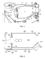
- Figure 1 shows a longitudinal cross-section through one side of a typical annular combustion system for an aero gas turbine engine.
- the combustion system has an annular combustion chamber 1 axially aligned with the axis of the engine, the combustion chamber being contained within radially outer 2 and inner 3 casings.
- Compressed air is ducted to the combustion chamber from the compressor section of the engine via a diffuser 4, which reduces the axial velocity of the compressed air and increases its pressure.
- the ducted air passes into the combustion chamber 1 through holes in a meter panel 5 at the forward end of the combustion chamber and also along cavities formed between the outer 2 and inner 3 casings and the corresponding barrel-shaped outer 6 and inner 7 combustion liners which extend rearwardly from the meter panel to define respective walls of the combustion chamber. Openings in the combustion liners allow the ducted air to enter the combustion chamber from these cavities.
- Fuel is introduced into the forward end of the combustion chamber 1 by fuel injectors 8, such as airspray nozzles.
- fuel injectors 8 such as airspray nozzles.
- the hot combusted gases enter the turbine section of the engine, via an annular gap formed between radially outer 9 and inner 10 discharge nozzles which extend rearwardly from respectively the outer 6 and inner 7 combustion liners.
- the first element of the turbine section encountered by the hot gases is typically a row of nozzle guide vanes (NGVs) 11.
- the combustion chamber 1 must be mounted to the engine in such a way as to accommodate significant differential thermal movements.
- the mounting arrangement comprises an attenuation arm or cone 12 which extends from the outer combustion liner 6 to the outer casing 2. This arm provides axial and radial restraint, but being relatively flexible allows a degree of movement of the combustion chamber, particularly in the radial direction of the engine.
- the mounting arrangement further comprises a bayonet-style fixing 13 between two rows of spaced teeth respectively formed at a projection at the rearward end of inner discharge nozzle 10 and a mating projection at the forward end of the NGV inner platform 14. This fixing provides axial restraint in the event of a surge.
- combustion chamber 1 is essentially axially fixed relative to the casings 2, 3 at its rearward end, differential thermal contractions or expansions in the axial direction of the engine between the combustion chamber and the casings produce their largest relative axial movements at the forward end of the combustion chamber.
- the interface of the fuel injectors 8 to the combustion chamber is configured to accommodate these movements.
- the attenuation arms 12 and bayonet-style fixing 13 also have to be strong enough to cope with surge events. These events involve the loss of compressor delivery pressure, resulting in a net axially forward piston-type load on the combustor chamber.
- the surge load is reacted by the attenuation arms and bayonet-style fixing restraining the outer 6 and inner 7 liners at their rearward ends, the combustor being generally insufficiently stiff to react this load at the end of only one of the liners without excessive deformation and the risk of damage.
- the combustor chamber geometry and its relationship to adjacent components are maintained. That part of the surge load applied to the NGV inner platform 14 is transmitted forwards via the inner casing 3 and diffuser 4, to the outer engine casings.
- Some civil aero gas turbine engines mount the combustion chamber to the outer casing at the forward end of the chamber so that the maximum relative axial movement between the chamber and the casings is removed to the rearward end of the chamber.
- the resulting lack of significant relative axial movement between the fuel injectors and combustion chamber front is considered advantageous to certain aspects of engine performance.
- the relative movement can be accommodated by sliding seals between the outer and inner combustion liners and their respective outer and inner discharge nozzles.
- a first aspect of the present invention provides a combustor system for a gas turbine engine, the combustor system including:
- the clearance between the first stop surface and the first baulking surface can be enough to accommodate relative axial movement between the chamber and the selected casing caused by thermal expansion of the combustion chamber during normal engine operation.
- the first stop surface and the first baulking surface can be positioned so that they move into engagement and react the load on the combustion chamber to the selected liner during a surge event. That is, they can provide a surge bump stop.
- the combustor system may have any one or, to the extent that they are compatible, any combination of the following optional features.
- the attachment arrangement also radially restrains the rearward end of the combustion chamber relative to the casings.
- the selected casing is the inner casing.
- the attachment arrangement reacts axial loads on the combustion chamber to the other of the outer and inner casings. In this way, both the radially inner and radially outer sides of the combustion chamber can be axially restrained during a surge event, which can help to preserve the integrity of the combustion chamber.
- the attachment arrangement may extend from the combustion chamber directly or indirectly to the other of the outer and inner casings.
- the attachment arrangement at the rearward end of the combustion chamber may not need to react axial loads on the combustion chamber to the selected casing. This can reduce component costs and simplify assembly procedures. For example, particularly if the selected casing is the inner casing, a bayonet-style fastening of the type shown in Figure 1 (between the rearward end of an inner discharge nozzle and the forward end of an NGV inner platform) reacting axial loads on the combustion chamber to inner casing may be unnecessary.
- the attachment arrangement typically also radially restrains the rearward end of the combustion chamber relative to the casings.
- the combustor system can then further include a second stop surface formed at the forward end of the combustion chamber adjacent the selected casing, and a corresponding second baulking surface formed by the selected casing, the second stop surface and the second baulking surface being radially spaced from each other to allow radial movement of the forward end of the combustion chamber relative to the selected casing, the amount of relative radial movement being limited by engagement of the second stop surface with the second baulking surface.
- the second stop surface and the second baulking surface can help to avoid excessive bending moments at the rearward end of the combustion chamber and in the attachment arrangement.
- the combustion chamber typically has a barrel-shaped outer combustion liner, a barrel-shaped inner combustion liner coaxial with the outer combustion liner, and a ring-shaped meter panel which extends between forward ends of the outer and inner combustion liners.
- the first stop surface can then be formed by a projection extending from the meter panel towards the selected casing.
- the combustion chamber also has a second stop surface, that surface may also be formed by the projection.
- the projection and/or the selected casing can contain flow passages, such as through-holes of edge recesses, which allow compressed air delivered by the compressor of the engine to flow past the projection and into the cavity formed between the selected casing and the corresponding combustion liner.
- a second aspect of the present invention provides a gas turbine engine having the combustor system of the first aspect, the combustor system optionally having any one, or to the extent that they are compatible, any combination of the optional features of the first aspect.
- FIG 2 shows a schematic longitudinal cross-section through one side of an annular combustion system according to the present invention.
- An annular combustion chamber 101 has a barrel-shaped outer 106 and inner 107 combustion liners.
- a meter panel 105 extends between the forward edges of these two liners.
- the chamber is housed in the annular space formed between a radially outer casing (not shown) and a radially inner casing 103.
- Fuel injectors (not shown) extend through openings 115 in the meter panel to introduce fuel into the chamber.
- the rearward end of the combustion chamber 101 is mounted to the engine via a connection 116 (e.g. a weld or mechanical fastening) between a rearward edge of the outer liner 106 and a forward edge of outer discharge nozzle 109.
- a connection 116 e.g. a weld or mechanical fastening
- Loads transmitted from the outer liner to the outer discharge nozzle are transmitted further by paths (not shown) to the outer casing.
- the outer discharge nozzle in turn can be fastened via e.g. slot rivets (as described in WO 01/64368 A1 ) to an outer platform of the NGVs of the turbine section.
- the mounting provides both an axial and radial restraint on the combustion chamber relative to the outer and inner 103 casings.
- connection 117 e.g. a weld or mechanical fastening
- connection 118 e.g. a weld or mechanical fastening
- This in turn is joined by a simple spigot arrangement 118 at its rearward edge to an inner platform 114 of the NGVs.
- the spigot fit provides radial location but no axial restraint. However, the stiffness and integrity of the combustor structure are adequate for such an attachment arrangement under normal running conditions.
- a physical "bump-stop" arrangement is provided as follows.
- the meter panel extends inboard as a ring-shaped projection 119 sufficiently far that a forward-facing stop surface 120 of the projection is located axially rearwardly of an extension feature 121 of the inner casing 103.
- a rearward-facing surface of the extension feature forms a baulking surface 122 is spaced from the stop surface, allowing the forward end of the combustion chamber to move axially forward relative to the inner casing as the chamber thermally expands under normal operating conditions.
- the stop surface makes contact with the baulking surface 122 to prevent excessive meter panel combustion chamber deflection.
- the inboard surface of the projection 119 and the radially facing surface of the casing form respectively a second pair of stop 123 and baulking 124 surfaces which steady the forward end of the combustor in the radial direction.
- the clearance, under normal operating conditions, between the second pair of stop and baulking surfaces is less than that between first pair of stop 120 and baulking 122 surfaces because the amount of relative radial movement caused by thermal expansion of the combustion chamber is less in the radial direction than in the axial direction.
- FIG. 3 is a perspective cut-away view of the annular combustion system of Figure 2 , and shows recesses 125 in the extension feature 121.
- the inner casing rearward of extension feature 121 is not shown in Figure 3 .
- the stop and baulking surfaces can reduce the complexity of the attachment arrangement at the rearward end of the combustion chamber needed to mount the chamber to the engine.
- a relatively simple spigot arrangement 118 at the inner side of the chamber can replace the bayonet-style fixing 13 of the combustor system of Figure 1 above.
Landscapes
- Engineering & Computer Science (AREA)
- Chemical & Material Sciences (AREA)
- Combustion & Propulsion (AREA)
- Mechanical Engineering (AREA)
- General Engineering & Computer Science (AREA)
- Turbine Rotor Nozzle Sealing (AREA)
Applications Claiming Priority (1)
| Application Number | Priority Date | Filing Date | Title |
|---|---|---|---|
| GBGB0920371.2A GB0920371D0 (en) | 2009-11-23 | 2009-11-23 | Combustor system |
Publications (2)
| Publication Number | Publication Date |
|---|---|
| EP2325564A2 true EP2325564A2 (de) | 2011-05-25 |
| EP2325564A3 EP2325564A3 (de) | 2017-12-27 |
Family
ID=41565628
Family Applications (1)
| Application Number | Title | Priority Date | Filing Date |
|---|---|---|---|
| EP10187485.7A Withdrawn EP2325564A3 (de) | 2009-11-23 | 2010-10-14 | Verbrennersystem |
Country Status (3)
| Country | Link |
|---|---|
| US (1) | US8511099B2 (de) |
| EP (1) | EP2325564A3 (de) |
| GB (1) | GB0920371D0 (de) |
Families Citing this family (4)
| Publication number | Priority date | Publication date | Assignee | Title |
|---|---|---|---|---|
| US9297536B2 (en) * | 2012-05-01 | 2016-03-29 | United Technologies Corporation | Gas turbine engine combustor surge retention |
| US20160298853A1 (en) * | 2015-04-09 | 2016-10-13 | Siemens Energy, Inc. | Service-friendly cross flame tube with twist lock attachment for can-annular gas turbines |
| US11306918B2 (en) * | 2018-11-02 | 2022-04-19 | Chromalloy Gas Turbine Llc | Turbulator geometry for a combustion liner |
| FR3084731B1 (fr) * | 2019-02-19 | 2020-07-03 | Safran Aircraft Engines | Chambre de combustion pour une turbomachine |
Citations (1)
| Publication number | Priority date | Publication date | Assignee | Title |
|---|---|---|---|---|
| WO2001064368A1 (en) | 2000-03-01 | 2001-09-07 | Rolls-Royce Plc | A joint for sheet material and a method of joining sheet material |
Family Cites Families (14)
| Publication number | Priority date | Publication date | Assignee | Title |
|---|---|---|---|---|
| US2625794A (en) * | 1946-02-25 | 1953-01-20 | Packard Motor Car Co | Gas turbine power plant with diverse combustion and diluent air paths |
| US2801520A (en) * | 1954-08-05 | 1957-08-06 | Axel L Highberg | Removable burner cans |
| GB1180706A (en) * | 1968-08-02 | 1970-02-11 | Rolls Royce | Flame Tube |
| US3842595A (en) * | 1972-12-26 | 1974-10-22 | Gen Electric | Modular gas turbine engine |
| US4195475A (en) * | 1977-12-21 | 1980-04-01 | General Motors Corporation | Ring connection for porous combustor wall panels |
| US4191011A (en) * | 1977-12-21 | 1980-03-04 | General Motors Corporation | Mount assembly for porous transition panel at annular combustor outlet |
| JPS599431A (ja) * | 1982-07-09 | 1984-01-18 | Hitachi Ltd | ガスタ−ビン燃焼器の支持装置 |
| GB2168755B (en) * | 1984-12-08 | 1988-05-05 | Rolls Royce | Improvements in or relating to gas turbine engines |
| US4785623A (en) | 1987-12-09 | 1988-11-22 | United Technologies Corporation | Combustor seal and support |
| FR2671857B1 (fr) * | 1991-01-23 | 1994-12-09 | Snecma | Chambre de combustion, notamment pour turbine a gaz, a paroi deformable. |
| FR2686683B1 (fr) * | 1992-01-28 | 1994-04-01 | Snecma | Turbomachine a chambre de combustion demontable. |
| FR2887015B1 (fr) | 2005-06-14 | 2010-09-24 | Snecma Moteurs | Assemblage d'une chambre de combustion annulaire de turbomachine |
| FR2905166B1 (fr) | 2006-08-28 | 2008-11-14 | Snecma Sa | Chambre de combustion annulaire d'une turbomachine. |
| FR2919380B1 (fr) | 2007-07-26 | 2013-10-25 | Snecma | Chambre de combustion d'une turbomachine. |
-
2009
- 2009-11-23 GB GBGB0920371.2A patent/GB0920371D0/en not_active Ceased
-
2010
- 2010-10-14 US US12/904,242 patent/US8511099B2/en not_active Expired - Fee Related
- 2010-10-14 EP EP10187485.7A patent/EP2325564A3/de not_active Withdrawn
Patent Citations (1)
| Publication number | Priority date | Publication date | Assignee | Title |
|---|---|---|---|---|
| WO2001064368A1 (en) | 2000-03-01 | 2001-09-07 | Rolls-Royce Plc | A joint for sheet material and a method of joining sheet material |
Also Published As
| Publication number | Publication date |
|---|---|
| US8511099B2 (en) | 2013-08-20 |
| US20110120141A1 (en) | 2011-05-26 |
| GB0920371D0 (en) | 2010-01-06 |
| EP2325564A3 (de) | 2017-12-27 |
Similar Documents
| Publication | Publication Date | Title |
|---|---|---|
| JP3907529B2 (ja) | ろう付けされたタブを用いたターボマシンにおけるcmc燃焼室の取り付け | |
| EP3404329B1 (de) | Brennkammerplattenendschienenschnittstelle | |
| JP3947429B2 (ja) | 希釈孔を用いたターボマシンにおけるcmc燃焼室の取り付け | |
| EP2236760B1 (de) | Thermisch entkoppeltes Übergangsstück einer Ringbrennkammer | |
| US9464808B2 (en) | Nozzle tip assembly with secondary retention device | |
| CA2605220C (en) | Gas turbine internal manifold mounting arrangement | |
| JP5435910B2 (ja) | ガスタービンシュラウド支持装置 | |
| EP2904236B1 (de) | Innenverkleidung für eine gasturbinenbrennkammer | |
| EP2959136B1 (de) | Brennkammer eines gasturbinenmotors mit gerippter zünderdichtung | |
| US11536454B2 (en) | Combustor wall assembly for gas turbine engine | |
| EP2103780B1 (de) | Kaltluftpuffer-Zuführungsleitung | |
| EP3080404B1 (de) | Schaufelprofil für eine gasturbine und zugehörige anordnung | |
| EP3214374B1 (de) | System für axial gestufte brennstoffzufuhr für eine gasturbinenbrennkammer | |
| US8511099B2 (en) | Combustor system | |
| CN102057224A (zh) | 包括cmc偏转部的气体涡轮机燃烧室 | |
| EP1706594A1 (de) | Bewegliche abdichtung zwischen brennkammerwand und schaufelplattform | |
| WO2015030928A1 (en) | Swirler mount interface for a gas turbine engine combustor | |
| CN108006696A (zh) | 燃烧器组件和燃烧器 | |
| KR20120019382A (ko) | 연소기 내 마모 유발 운동 감소 방법, 마모 감소형 연소기, 및 리테이너 | |
| EP2938834A1 (de) | Stossfänger für abdichtungen in einem turbinenabgasgehäuse | |
| EP3832206B1 (de) | Brennkammer für gasturbine | |
| CN116324130B (zh) | 用于涡轮喷射锥的密封组合件 | |
| US7770401B2 (en) | Combustor and component for a combustor | |
| US20130111910A1 (en) | Transition piece aft frame | |
| EP3044421B1 (de) | Funktionen zur druckstoss- und drehverhinderung auf einem ersten leitschaufelträger |
Legal Events
| Date | Code | Title | Description |
|---|---|---|---|
| PUAI | Public reference made under article 153(3) epc to a published international application that has entered the european phase |
Free format text: ORIGINAL CODE: 0009012 |
|
| AK | Designated contracting states |
Kind code of ref document: A2 Designated state(s): AL AT BE BG CH CY CZ DE DK EE ES FI FR GB GR HR HU IE IS IT LI LT LU LV MC MK MT NL NO PL PT RO RS SE SI SK SM TR |
|
| AX | Request for extension of the european patent |
Extension state: BA ME |
|
| RAP1 | Party data changed (applicant data changed or rights of an application transferred) |
Owner name: ROLLS-ROYCE PLC |
|
| PUAL | Search report despatched |
Free format text: ORIGINAL CODE: 0009013 |
|
| AK | Designated contracting states |
Kind code of ref document: A3 Designated state(s): AL AT BE BG CH CY CZ DE DK EE ES FI FR GB GR HR HU IE IS IT LI LT LU LV MC MK MT NL NO PL PT RO RS SE SI SK SM TR |
|
| AX | Request for extension of the european patent |
Extension state: BA ME |
|
| RIC1 | Information provided on ipc code assigned before grant |
Ipc: F23R 3/50 20060101ALI20171123BHEP Ipc: F23R 3/60 20060101AFI20171123BHEP |
|
| STAA | Information on the status of an ep patent application or granted ep patent |
Free format text: STATUS: THE APPLICATION HAS BEEN PUBLISHED |
|
| STAA | Information on the status of an ep patent application or granted ep patent |
Free format text: STATUS: THE APPLICATION IS DEEMED TO BE WITHDRAWN |
|
| 18D | Application deemed to be withdrawn |
Effective date: 20180528 |