EP2324935B1 - Chute for sorting apparatus and sorting apparatus provided with such a chute - Google Patents
Chute for sorting apparatus and sorting apparatus provided with such a chute Download PDFInfo
- Publication number
- EP2324935B1 EP2324935B1 EP10183440A EP10183440A EP2324935B1 EP 2324935 B1 EP2324935 B1 EP 2324935B1 EP 10183440 A EP10183440 A EP 10183440A EP 10183440 A EP10183440 A EP 10183440A EP 2324935 B1 EP2324935 B1 EP 2324935B1
- Authority
- EP
- European Patent Office
- Prior art keywords
- guiding element
- chute
- products
- range
- guiding
- Prior art date
- Legal status (The legal status is an assumption and is not a legal conclusion. Google has not performed a legal analysis and makes no representation as to the accuracy of the status listed.)
- Not-in-force
Links
Images

Classifications
-
- B—PERFORMING OPERATIONS; TRANSPORTING
- B07—SEPARATING SOLIDS FROM SOLIDS; SORTING
- B07C—POSTAL SORTING; SORTING INDIVIDUAL ARTICLES, OR BULK MATERIAL FIT TO BE SORTED PIECE-MEAL, e.g. BY PICKING
- B07C5/00—Sorting according to a characteristic or feature of the articles or material being sorted, e.g. by control effected by devices which detect or measure such characteristic or feature; Sorting by manually actuated devices, e.g. switches
- B07C5/36—Sorting apparatus characterised by the means used for distribution
- B07C5/363—Sorting apparatus characterised by the means used for distribution by means of air
- B07C5/365—Sorting apparatus characterised by the means used for distribution by means of air using a single separation means
- B07C5/366—Sorting apparatus characterised by the means used for distribution by means of air using a single separation means during free fall of the articles
Definitions
- the present invention relates to a chute for a sorting apparatus, said chute being provided with an inclined surface for guiding products, in particular granular products, towards a detecting and selecting system of the sorting apparatus while moving under influence of gravity. It also relates to an apparatus for sorting products comprising such a chute.
- a sorting apparatus for in-line sorting of granular products is disclosed in European patent EP0952895 .
- This sorting apparatus comprises a detection system, a removal system and a transport device having a sloped distribution surface, which is convex over at least a certain distance in the direction of travel of the granular products.
- This transport device guides the products towards the detection and removal system such that products are analysed and selected while moving in a vertical downward direction.
- the curvature of this convex distribution surface is equal to or slightly less than then curvature of the path the falling products would follow if this convex distribution surface would be absent.
- this particular shape of the distribution surface forces the falling products to follow substantially congruent parabolic paths such that the position and speed of each falling product is predetermined, thereby rendering the process of analysing and selecting the falling products more easy.
- this convex shape is present, there is still a large variation on the trajectories of the falling products such that the spacing between the removal system and the falling products cannot be minimised, thereby resulting in an unwanted removal of high-quality products.
- the variation on the trajectory, i.e. position and speed, of each individual product renders the synchronisation of the detection system and the removal system more difficult.
- This sorting apparatus also comprises a detection system, a removal system and a chute having a curved surface in the shape of a ski jump having a monotonic increase of the curvature of this surface towards the detection system.
- This chute projects the products in an upward direction towards the detection and removal system such that the products are analysed and selected while moving in a horizontal forward direction. It is claimed that while gliding downwards along the curved surface of the chute the position of the products is stabilised due to the centrifugal forces acting thereupon. Although a more stabile product stream can be obtained, the projection of the products in a upward direction when leaving the chute introduces variation on the trajectory of projected products which makes the subsequent analysis and removal process more complex and less selective. Also here the position of the detection system makes it more prone to be dirtied by products having a trajectory, which differs from the mean path of the product stream, and consequently the quality of the detection system can be impaired.
- the present invention aims to provide a chute that overcomes the above problems of the prior art solutions.
- the invention aims to provide a sorting apparatus equipped with such a chute.
- the present invention relates to a chute adapted for guiding a stream of products, moving under influence of gravity, in an essentially vertical downward direction allowing the analysis and selection of the products while in free fall.
- the chute configuration also offers a better control over the trajectory of the falling products such that the spacing between the selecting system and the product stream can be minimised.
- a chute comprising a first guiding element.
- This first guiding element has a downwardly-curved surface over its entire length towards the detection system, i.e. along the direction in which the products propagate. If this surface is expressed by a function F 1 , this means in particular, that for the second derivative of this function F 1 it holds that / d ⁇ x 2 d 2 ⁇ F 1 ⁇ 0 over the complete width of said first guiding element.
- DF1 hereby denotes the first derivative.
- the chute comprises, in addition to the first guiding element, a second guiding element.
- This second guiding element has a surface which is adapted for redirecting products which are propelled by the first guiding element towards the second guiding element and received by the second guiding element in an essentially vertical downward direction.
- the surface of the second guiding element is upwardly-curved over at least a certain section along the movement of the product stream such that products propelled towards this upwardly-curved section are redirected by this upwardly-curved section in an essentially vertical downward direction.
- the surface of the second guiding element is preferably shaped to be initially tangential to this mean velocity vector.
- the second guiding element is convexly curved in the downward direction over its entire length.
- the second guiding element has downstream an upwardly-curved section parallel with the product stream and upstream a downwardly-curved section.
- the curvature of the second guiding element can be described by a spline function characterised by the following control points :
- CP F 2 m x m x U n x n x m y T U m x ⁇ U T U n x n y
- the present invention discloses an apparatus for sorting products, in particular granular products such as raisins, blueberries but also pellets e.g. plastic pellets.
- the sorting apparatus comprises a supply system for providing products in a continuous stream to a chute as previously described.
- This chute guides the supplied products, while moving under gravity, towards a detection system and a removal system, the chute comprising a first guiding element having a downwardly-curved surface and, optionally, a second guiding element as in the above-mentioned embodiments of the invention.
- the detection system is positioned to analyse the products when moving in a substantially vertical direction.
- the configuration of the sorting apparatus is such that the first guiding element is positioned on one side of the product stream and the removal system and, if present, the second guiding element is positioned at the opposite side of the product stream.
- Fig. 1 represents a schematic view of a sorting apparatus according to an embodiment of the invention.
- Fig. 2 represents a schematic view of the chute illustrating the parameters determining the shape and relative position of the first guiding element of the chute.
- Fig. 3 represents a schematic view of a sorting apparatus provided with a first and a second guiding element according to an embodiment of the invention.
- Fig. 4 represents a schematic view of the chute illustrating the parameters determining the shape and relative position of the first and second guiding element of the chute.
- Fig. 5 represents a detailed schematic view of the chute illustrating a particular shape and relative position of the first and second guiding element of the chute according to the present invention.
- the present invention discloses an apparatus for sorting products, in particular granular products such as raisins, blueberries but also pellets e.g. plastic pellets, which are supplied in a continuous stream.
- the present invention discloses a chute for guiding the stream of products when moving in a vertical downward direction due to gravity, which can be used in such sorting apparatus.
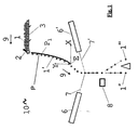
- FIG. 1 illustrates a sorting apparatus (10) according to a first embodiment of the present invention.
- This apparatus for sorting products (1) comprises a supply system (3), at least one detection system (6,6'), a removal system (8) and a chute (P) which guides the stream of products, supplied by the supply system (3), towards the detection system (6, 6') and the removal system (8) while moving under influence of gravity.
- This supply system (3) can be a conveyor belt, a shaker, a vibrating table or any transporting means known in the art.
- the product granules are individually scanned by a detection system (6, 6'), preferably both from a front (6) and a rear position (6').
- the detection system (6, 6') can comprise at least one light source directing a concentrated light beam (7, 7'), such as a laser beam, for scanning the products (1') and at a least one detector, such as a photo multiplier tube, but likewise a CCD camera is suitable as well, for receiving light reflected from the products (1').
- a concentrated light beam (7, 7') such as a laser beam
- a detector such as a photo multiplier tube, but likewise a CCD camera is suitable as well, for receiving light reflected from the products (1').
- the sensed signal will be analysed and lesser quality products or foreign bodies will be detected.
- a signal is given to the removal system (8).
- this removal system (8) is a manifold of air pressure valves which can be opened on command.
- an element (2) can be mounted above the supply system (3) at the point where the products (1) are transferred from the supply system (3) to the chute (P).
- the products (1) when going from the supply system (3) to the chute (P) will be pushed again this element (2) such that products are more uniformly distributed over the product stream and a thinner product stream towards the chute (P) is obtained.
- This element (2) can be a flexible flap mounted on a horizontal axis and which is made of rubber, plastic, leather or any kind of flexible material known in the art. This axis is located at the end of the supply system (3) adjacent the chute (P) and is perpendicular to the direction (9) in which the products (1) are being propagated.
- the first guiding element (P 1 ) of the chute (P) has a downwardly-curved surface, i.e. the curvature of this surface is concave in the gravitational direction.
- the first guiding element (P 1 ) has a surface which is downwardly-curved over its entire length towards the detection system (6, 6'), i.e. along the direction (9) in which the products (1') propagate. The products will fall from the supply system (3) on the chute (P) and glide downwards to the detection system (6, 6'), the position of the products being stabilised due to the centrifugal forces acting thereupon.
- first guiding element (P 1 ) of the chute (P) illustrated in Fig. 1 thus has a downward parabolic surface such that the chute is downwardly sloped over its entire length along the propagation direction (9) of the products (1').
- first guiding element (P 1 ) of the chute (P) is shaped such that when the falling products (1') leave the chute (P), they are propelled downward towards the detection system (6, 6').
- each granule normally has a nominal speed of approximately 2 m / s .
- the product goes into free-fall thereby describing a parabolic curve.
- the products (1') will finally propagate in an essentially vertical downward direction. From this point onwards products (1') will be analysed by the detection system (6, 6'). As shown in Fig.1 , the concentrated light beam (7, 7') of the detection system (6, 6') is directed to the product stream where propagating in an essentially vertical direction.
- the chute (P) is positioned below the product stream to carry the product stream. Due to this configuration one can position the removal system (8) downstream the product stream and opposite the side where the chute (P) is placed. The removal system (8) can even be positioned such that the distance between the removal system (8) and the product stream is minimised. Given the fact that the product stream is more confined, the average distance between the removal system (8) and the free-falling products can be greatly reduced.
- the removal system (8) comprises a manifold of air-pressure valves, which often is the case, the effective removal area of one such valve at this short distance from the falling product is, contrary to prior art sorting apparatus, no more much larger than the size of a typical granule such as a raisin or a peanut. As a result the false reject, i.e. the amount of good product which has been removed, is considerably reduced.
- a detailed description is given below to determine the configuration of the first guiding element (P 1 ) of a chute (P) according to a first embodiment of the invention, the shape of which can be selected according to the description given below.
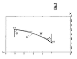
- Fig.2 illustrates the mathematical modelling of this first guiding element (P 1 ).
- the curvature of this first element (P 1 ) is fully described by a B-spline P 1 .
- the origin of this B-spline function is placed on the outgoing point of the first guiding element (P 1 ), i.e. at is lowest point E.
- P 1 describes a cubic spline, i.e. the number of knots minus the number of constraints is four.
- the current invention is however not limited to this particular mathematical formulation, as long as the first guiding element (P 1 ) is downwardly sloped over its entire length along the propagation direction (9) such that the products (1') are leaving the first guiding element (P 1 ) in a direction which is equal or less than the horizontal direction X as shown in Fig.1 .
- F x M ⁇ g ⁇ cos arc ⁇ tan d ⁇ F 1 d ⁇ x , where g is the acceleration due to gravitation. Because one is only interested in the speed of a granule at the point where it leaves the first guiding element (P 1 ), M can be assumed to be one, i.e. the speed is independent of mass.
- the dimensions of the first guiding element are selected from the following ranges :
- the angle ⁇ should preferably be between 70 and 90 degrees, preferably selected from the range 80 to 90 degrees, more preferably this angle is about 90 degrees.
- the angle ⁇ is selected from the range 20 to 85 degrees, preferably selected from the range of 40 to 85 degrees and is preferably about 80 degrees.
- the knot ( ⁇ , ⁇ y ) is varied to such an extent that the first guiding element (P 1 ) of the chute (P) is concave in the downward direction.
- the knot ( ⁇ , ⁇ y ) is taken to be (0.0779m, 0.1279m), measured in an XY reference system as depicted in Fig.2 .
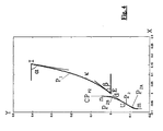
- Fig.3 illustrates a sorting apparatus (10) according to another preferred embodiment of the present invention.
- the sorting apparatus comprises a supply system (3), a detection system (6,6'), a removal system (9) and a chute (P) which guides the stream of products, supplied by the supply system (3), towards the detection system (6, 6') and the removal system (8) while moving under influence of gravity.
- This supply system (3) can be a conveyor belt, a shaker or any transporting means known in the art.
- the product granules are individually scanned by a detection system, preferably both from a front (6) and a rear position (6').
- the detection system can comprise a laser and a photo multiplier tube, but likewise a CCD camera is suitable as well.
- the sensed signal will be analysed and lesser quality product or foreign bodies will be detected.
- a signal is given to the removal system (8).
- this removal system (8) is a manifold of air pressure valves which can be opened on command. This allows the rejected element (1") to be blown out of the product stream as soon as it enters the cone of high pressured air produced by such a valve, while the accepted elements (1"') continue their movement.
- the present invention is however not limited to an air pressure based removal system.
- a element (2) can mounted above the supply system (3) at the point where the products (1) are transferred from the supply system (3) to the chute (P). The products (1) when going from the supply system (1) to the chute (P) will be pushed again this element (2) such that products are more uniformly distributed over the product stream and a thinner product stream towards the chute (P) is obtained.
- the chute (P) comprises a first guided element (P 1 ) as previously discussed, which has a downwardly-curved surface, i.e. the curvature of this surface is concave in the gravitational direction, and further a second guiding element (P 2 ) having an upwardly-curved surface, i.e. at least a part of its surface is convex in the gravitational direction.
- the products will fall from the supply system (3) on the first guiding element (P 1 ) and glide downwards to the second guiding element (P 2 ).
- the chute illustrated in Fig.3 thus comprises upstream a first guiding element (P 1 ) having a downward parabolic surface and downstream a second guiding element (P 2 ), at least one section (P 2A ) thereof has an upward parabolic surface.
- both guiding elements (P 1 , P 2 ) are positioned with respect to each other, such that when the falling products (1') leave the first guiding element (P 1 ) they are propelled towards the second guiding element (P 2 ) to be received thereby (P 2A ).
- each granule normally has a nominal speed of approximately2 m / s .
- the product goes into free-fall thereby describing a parabolic curve.
- the product will reach the second guiding element (P 1 ) at a predetermined point (U). From that point onwards the second guiding element (P 2 ) will guide the product to an essentially vertical downward direction.
- the receiving section (P 2A ) of this second guiding element (P 2 ) is shaped to be initially parallel with the mean velocity vector of the incoming product stream thereby minimising the risk of the products to bounce back upon impact with the second guiding element (P 2 ). Due to its convex shape the second guiding element (P 2 ) first receives the products at point (U) and then redirects them in a vertically downward direction.
- the velocity vector (V) of the propelled products as determined by the curvature of the first guiding element (P 1 ) is gradually redirected from a more horizontal direction to a vertical direction thanks to the smoothly curved surface of the second guiding element (P 2 ) resulting in a free fall of the products with well controlled position and speed.
- the trajectories of the falling products are better controlled thereby reducing the spread thereof.
- the second guiding element (P 2 ) will substantially minimise the spinning of the falling products such that shape detection of these products can be done more accurately.
- the second guiding element (P 2 ) need only to have a section (P 2A ) with a downwardly curved surface from impact point (U) downwards. All trajectories of the propelled product should reach the second guiding element (P 2 ) at this point (U) or below. However some outlier products may have a deviating trajectory which leads them above this point (U). These products will then be lost.
- a second section (P 2B ) can be placed in the second guiding element (P 2 ) at a position above this point (U).
- This upstream section (P 2B ) preferably has a downward parabolic shape as shown in Fig.3 .
- this second section (P 2B ) will prevent such outliers from travelling beyond the second guiding element (P 2 ) by either bouncing them back to the first guiding element (P 1 ) or by guiding them directly to the downstream convex section (P 2A ).
- this section (P 2B ) can be designed to have a straight shape which is more or less parallel to the trajectory of the incoming products. The latter alternative might be easier to manufacture as the second guiding element (P 2 ) can then be constructed from a straight plate only requiring one end of it (P 2A ) to be curved according to the required specifications.
- the first guiding element (P 1 ) is positioned below the product stream to carry the product stream, while the second guiding element (P 2 ) is positioned downstream and above the product stream to prevent the propelled products to move further in horizontal direction. Due to this configuration one can position the removal system (8) downstream and at the same side as the second guiding element (P 2 ) as it this second guiding element (P 2 ) will prevent residues or products being deposited on the removal system (8).
- the removal system (8) can even be positioned parallel in vertical direction with the second guiding element such that the distance between the removal system (8) and the product stream is minimised. Given the fact that the product stream is more confined the average distance between the removal system (8) and the free-falling products can greatly reduced.
- the removal system (8) comprises a manifold of air-pressure valves, which is often the case, the effective removal area of one such valve at this short distance from the falling product is, contrary to prior art sorting apparatus, no more much larger than the size of a typical granule such as a raisin or a peanut. As a result the false reject, i.e. the amount of good product which has been removed, will be considerably reduced.
- a detailed description is given below to determine the configuration of a chute (P) according to this second aspect of the invention: the shape and the relative position of each guiding element (P 1 , P 2 ) can be selected according to the description given below.
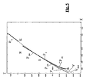
- Fig.4 illustrates the mathematical modelling of the both elements (P 1 ,P 2 ).
- the curvature of the first element (P1) is fully given by a B-spline F 1 .
- the origin is placed on the outgoing point of the first plate.
- F 1 describes a cubic spline, i.e. the number of knots minus the number of constraints is four.
- the present invention is however not limited to this particular mathematical formulation.
- n x n y and m x m y are the rightmost (n) and leftmost (m) points on the second plate ( P 2 ), respectively.
- the control points CP F 2 ensure that the outgoing direction of granules along P 2 is vertical.
- the vertical distance between point (I) and point (m), i.e. the height of the chute (P), can vary between 0.1m and 1.2m.
- the height of the first guiding element (P 1 ), measured between point (I) and point (E), is preferably between 0.3m and 0.8m and the height of the second guiding element (P 2 ), measured between point (n) and point (m), is preferably between 0.05m and 0.4m.
- the horizontal distance between point (I) and point (m), i.e. the width of the chute (P), can vary between 0.15m and 0.7m.
- the width of the first guiding element (P1), measured between point (I) and point (E), is preferably between 0.05m and 0.4m and the width of the second guiding element (P2), measured between point (n) and point (m), is preferably between 0.02m and 0.3m.
- This selection of parameters thus results in a second guiding element (P 2 ) of the chute (P) having only the downstream section (P 2A ) curved.
- This embodiment is illustrated in Fig.5 .
- the angle ⁇ , indicative for the slope of the first guiding element (P 1 ) near the supply system (3) and measured counter clockwise relative to the horizontal axis, should preferably be between 70 and 90 degrees and more preferably about 80 degrees.
- the angle ⁇ , indicative for the slope of the first guiding element (P 1 ) at the end remote from the supply system (3) and measured clockwise relative to the horizontal axis, is preferably between 20 and 80 degrees and more preferably about 50 degrees.
- the knot ( ⁇ , ⁇ y ) is varied to such an extent that the first guiding element (P 1 ) of the chute (P) is concave in the downward direction.
- the knot( ⁇ , ⁇ y ) is taken to be (0.0799m, 0.1279m), measured in an XY reference system such as depicted in Fig.4 .
Description
- The present invention relates to a chute for a sorting apparatus, said chute being provided with an inclined surface for guiding products, in particular granular products, towards a detecting and selecting system of the sorting apparatus while moving under influence of gravity. It also relates to an apparatus for sorting products comprising such a chute.
- A sorting apparatus for in-line sorting of granular products is disclosed in European patent
EP0952895 . This sorting apparatus comprises a detection system, a removal system and a transport device having a sloped distribution surface, which is convex over at least a certain distance in the direction of travel of the granular products. This transport device guides the products towards the detection and removal system such that products are analysed and selected while moving in a vertical downward direction. The curvature of this convex distribution surface is equal to or slightly less than then curvature of the path the falling products would follow if this convex distribution surface would be absent. It is claimed that this particular shape of the distribution surface forces the falling products to follow substantially congruent parabolic paths such that the position and speed of each falling product is predetermined, thereby rendering the process of analysing and selecting the falling products more easy. Although this convex shape is present, there is still a large variation on the trajectories of the falling products such that the spacing between the removal system and the falling products cannot be minimised, thereby resulting in an unwanted removal of high-quality products. The variation on the trajectory, i.e. position and speed, of each individual product renders the synchronisation of the detection system and the removal system more difficult. Moreover due to the convex shape of the distribution surface it is difficult to stabilise the orientation of the falling products towards the detection system such that a maximal projected area of the product is offered for analysis. Certainly if hard products are being transported such products tend to bounce on the distribution surface thereby following a path that deviates from the desired congruent parabolic path. Products having a trajectory, which differs from the mean congruent path of the product stream, may be deposited upon the detection system and consequently the quality of the detection system can be impaired. - Another sorting apparatus is disclosed in German patent
DE19708457 . This sorting apparatus also comprises a detection system, a removal system and a chute having a curved surface in the shape of a ski jump having a monotonic increase of the curvature of this surface towards the detection system. This chute projects the products in an upward direction towards the detection and removal system such that the products are analysed and selected while moving in a horizontal forward direction. It is claimed that while gliding downwards along the curved surface of the chute the position of the products is stabilised due to the centrifugal forces acting thereupon. Although a more stabile product stream can be obtained, the projection of the products in a upward direction when leaving the chute introduces variation on the trajectory of projected products which makes the subsequent analysis and removal process more complex and less selective. Also here the position of the detection system makes it more prone to be dirtied by products having a trajectory, which differs from the mean path of the product stream, and consequently the quality of the detection system can be impaired. - The present invention aims to provide a chute that overcomes the above problems of the prior art solutions. In another aspect the invention aims to provide a sorting apparatus equipped with such a chute.
- The present invention relates to a chute adapted for guiding a stream of products, moving under influence of gravity, in an essentially vertical downward direction allowing the analysis and selection of the products while in free fall. As the products are stabilised while moving along the chute the selection process can be performed more accurately, thereby reducing unwanted removal of good products or bad products not being removed. The chute configuration also offers a better control over the trajectory of the falling products such that the spacing between the selecting system and the product stream can be minimised.
- In a first embodiment of the invention a chute is disclosed comprising a first guiding element. This first guiding element has a downwardly-curved surface over its entire length towards the detection system, i.e. along the direction in which the products propagate. If this surface is expressed by a function F1, this means in particular, that for the second derivative of this function F1 it holds that

- In a preferred embodiment the dimensions of the first guiding element are selected from the following ranges:
- the height of the first guiding element measured between point (I) and point (E), is selected from the range 0.3m to 0.8m, and is preferably at about 0.5m and
- the width of the first guiding element, i.e. the horizontal distance between point (I) and point (E), is selected from the range 0.05m to 0.4m, preferably selected from the range 0.05m to 0.2m, and is preferably about 0.15m,and
- the angle α is selected from the range 70 to 90 degrees, preferably selected from the range 80 to 90 degrees, more preferably this angle is about 90 degrees, and
- the angle β is selected from the range 20 to 85 degrees, preferably selected from the range 40 to 85 degrees and is preferably about 80 degrees.
- In another embodiment the curvature of this first guiding element can be described by a B-spline function F1 having a knot sequence given by K1 =[0 0 0 0 κ l l l l], where 0 is the origin, κ is a sliding knot controlling the curvature and l is the horizontal dimension of the first guiding element, further specified by the following constraints: F 1(0)=0, F 1(l)=h, F 1(κ)=κ y , DF 1(l)=tanα, DF 1(0)=tanβ. DF1 hereby denotes the first derivative.
- In an advantageous embodiment the chute comprises, in addition to the first guiding element, a second guiding element. This second guiding element has a surface which is adapted for redirecting products which are propelled by the first guiding element towards the second guiding element and received by the second guiding element in an essentially vertical downward direction.
- The surface of the second guiding element is upwardly-curved over at least a certain section along the movement of the product stream such that products propelled towards this upwardly-curved section are redirected by this upwardly-curved section in an essentially vertical downward direction. As the stream of products when being propelled towards this upwardly-curved section is characterised by a mean velocity vector, the surface of the second guiding element is preferably shaped to be initially tangential to this mean velocity vector.
- In a specific embodiment the second guiding element is convexly curved in the downward direction over its entire length.
- In another embodiment the second guiding element has downstream an upwardly-curved section parallel with the product stream and upstream a downwardly-curved section.
- In a preferred embodiment a chute provided with a first and a second guiding element has dimensions selected from the following ranges :
- the height of the chute , i.e. the vertical distance between point (I) and point (m), is selected from the range 0.1m to 1.2m, whereby the height of the first guiding element, measured between point (I) and point (E), is selected from the range 0.3m to 0.8m, and the height of the second guiding element, measured between point (n) and point (m), is selected from the range 0.05m to 0.4m,
- the width of the chute, i.e. the horizontal distance between point (I) and point (m), is selected from the range 0.15m to 0.7m., whereby the width of the first guiding element, measured between point (I) and point (E), is selected from the range 0.05m to 0.4m, and the width of the second guiding element, measured between point (n) and point (m), is selected from the range 0.02m and 0.3m.,
- the angle α is selected from the range 70 to 90 degrees and is preferably about 80 degrees, and
- the angle β is selected from the range 20 to 80 degrees and is preferably about 50 degrees.
- In another embodiment the curvature of the second guiding element can be described by a spline function characterised by the following control points :

- In another aspect the present invention discloses an apparatus for sorting products, in particular granular products such as raisins, blueberries but also pellets e.g. plastic pellets. The sorting apparatus comprises a supply system for providing products in a continuous stream to a chute as previously described. This chute guides the supplied products, while moving under gravity, towards a detection system and a removal system, the chute comprising a first guiding element having a downwardly-curved surface and, optionally, a second guiding element as in the above-mentioned embodiments of the invention. The detection system is positioned to analyse the products when moving in a substantially vertical direction. Preferably the configuration of the sorting apparatus is such that the first guiding element is positioned on one side of the product stream and the removal system and, if present, the second guiding element is positioned at the opposite side of the product stream.
- For the purpose of teaching the invention schematic viewings and cross-sections of a sorting apparatus or chute according to various embodiments of the invention are given. These drawings are not to scale. Like numerals are given to like elements in each drawing.
-
Fig. 1 represents a schematic view of a sorting apparatus according to an embodiment of the invention. -
Fig. 2 represents a schematic view of the chute illustrating the parameters determining the shape and relative position of the first guiding element of the chute. -
Fig. 3 represents a schematic view of a sorting apparatus provided with a first and a second guiding element according to an embodiment of the invention. -
Fig. 4 represents a schematic view of the chute illustrating the parameters determining the shape and relative position of the first and second guiding element of the chute. -
Fig. 5 represents a detailed schematic view of the chute illustrating a particular shape and relative position of the first and second guiding element of the chute according to the present invention. - The present invention discloses an apparatus for sorting products, in particular granular products such as raisins, blueberries but also pellets e.g. plastic pellets, which are supplied in a continuous stream. In particular the present invention discloses a chute for guiding the stream of products when moving in a vertical downward direction due to gravity, which can be used in such sorting apparatus.
-
Figure 1 illustrates a sorting apparatus (10) according to a first embodiment of the present invention. This apparatus for sorting products (1) comprises a supply system (3), at least one detection system (6,6'), a removal system (8) and a chute (P) which guides the stream of products, supplied by the supply system (3), towards the detection system (6, 6') and the removal system (8) while moving under influence of gravity. This supply system (3) can be a conveyor belt, a shaker, a vibrating table or any transporting means known in the art. After leaving the chute (P) the product granules are individually scanned by a detection system (6, 6'), preferably both from a front (6) and a rear position (6'). The detection system (6, 6') can comprise at least one light source directing a concentrated light beam (7, 7'), such as a laser beam, for scanning the products (1') and at a least one detector, such as a photo multiplier tube, but likewise a CCD camera is suitable as well, for receiving light reflected from the products (1'). In any case the sensed signal will be analysed and lesser quality products or foreign bodies will be detected. When the decision is taken to remove certain products from the product flow, a signal is given to the removal system (8). Typically this removal system (8) is a manifold of air pressure valves which can be opened on command. This allows the rejected element (1") to be blown out of the product stream as soon as it enters the cone of high pressured air produced by such a valve, while the accepted elements (1"') continue their movement. The present invention is however not limited to an air pressure based removal system. Optionally an element (2) can be mounted above the supply system (3) at the point where the products (1) are transferred from the supply system (3) to the chute (P). The products (1) when going from the supply system (3) to the chute (P) will be pushed again this element (2) such that products are more uniformly distributed over the product stream and a thinner product stream towards the chute (P) is obtained. This element (2) can be a flexible flap mounted on a horizontal axis and which is made of rubber, plastic, leather or any kind of flexible material known in the art. This axis is located at the end of the supply system (3) adjacent the chute (P) and is perpendicular to the direction (9) in which the products (1) are being propagated. - The first guiding element (P1) of the chute (P) has a downwardly-curved surface, i.e. the curvature of this surface is concave in the gravitational direction. The first guiding element (P1) has a surface which is downwardly-curved over its entire length towards the detection system (6, 6'), i.e. along the direction (9) in which the products (1') propagate. The products will fall from the supply system (3) on the chute (P) and glide downwards to the detection system (6, 6'), the position of the products being stabilised due to the centrifugal forces acting thereupon. When leaving the chute (P) at its bottom point, the stream of products will have a substantially uniform thickness, with a small thickness distribution in a direction perpendicular to the chute (P). Typically the thickness of the product stream is substantially equal to the thickness of a single product (1). The first guiding element (P1) of the chute (P) illustrated in
Fig. 1 thus has a downward parabolic surface such that the chute is downwardly sloped over its entire length along the propagation direction (9) of the products (1'). As can been seen inFig.1 first guiding element (P1) of the chute (P) is shaped such that when the falling products (1') leave the chute (P), they are propelled downward towards the detection system (6, 6'). At the bottom end (E) of the first guiding element (P1) of the chute (P), each granule normally has a nominal speed of approximately 2m/s. At that point E the product goes into free-fall thereby describing a parabolic curve. Following this parabolic path the products (1') will finally propagate in an essentially vertical downward direction. From this point onwards products (1') will be analysed by the detection system (6, 6'). As shown inFig.1 , the concentrated light beam (7, 7') of the detection system (6, 6') is directed to the product stream where propagating in an essentially vertical direction. - As can be seen in
Fig.1 the chute (P) is positioned below the product stream to carry the product stream. Due to this configuration one can position the removal system (8) downstream the product stream and opposite the side where the chute (P) is placed. The removal system (8) can even be positioned such that the distance between the removal system (8) and the product stream is minimised. Given the fact that the product stream is more confined, the average distance between the removal system (8) and the free-falling products can be greatly reduced. Thus if the removal system (8) comprises a manifold of air-pressure valves, which often is the case, the effective removal area of one such valve at this short distance from the falling product is, contrary to prior art sorting apparatus, no more much larger than the size of a typical granule such as a raisin or a peanut. As a result the false reject, i.e. the amount of good product which has been removed, is considerably reduced. - To further illustrate the invention, a detailed description is given below to determine the configuration of the first guiding element (P1) of a chute (P) according to a first embodiment of the invention, the shape of which can be selected according to the description given below.
Fig.2 illustrates the mathematical modelling of this first guiding element (P1). - The curvature of this first element (P1) is fully described by a B-spline P1. By convention the origin of this B-spline function is placed on the outgoing point of the first guiding element (P1), i.e. at is lowest point E. The knot sequence describing P1 is given by

- In this set-up it is clear that P1 describes a cubic spline, i.e. the number of knots minus the number of constraints is four. The current invention is however not limited to this particular mathematical formulation, as long as the first guiding element (P1) is downwardly sloped over its entire length along the propagation direction (9) such that the products (1') are leaving the first guiding element (P1) in a direction which is equal or less than the horizontal direction X as shown in
Fig.1 . - The gravitational force F, as a function of x, acting on a granule which glides along a surface described by F1 is given by

where g is the acceleration due to gravitation. Because one is only interested in the speed of a granule at the point where it leaves the first guiding element (P1), M can be assumed to be one, i.e. the speed is independent of mass. - The work done by a granule following the path F1 can be expressed as


- In particular applications where products are sticky or have a tendency to deposit dirt at least on the first guiding element (P1), it can be taken into account that not all work is converted into kinetic energy. The speed of such a product is then given by

- If the product enters the first guiding element (P1) of the chute (P) having a given speed v0, the resulting speed is calculated as


- Preferably the dimensions of the first guiding element are selected from the following ranges :
- the height of the first guiding element (P1) measured between point (I) and point (E), is selected from the range 0.3m to 0.8m, and is preferably at about 0.5m and
- the width of the first guiding element (P1), i.e. the horizontal distance between point (I) and point (E), is selected from the range 0.05m to 0.4m, preferably selected from the range 0.05m to 0.2m, and is preferably about 0.15m, and
- the angle α, indicative for the slope of the first guiding element (P1) near the supply system (3) and measured counter clockwise relative to the horizontal axis, is selected from the range 70 to 90 degrees, preferably selected from the range 80 to 90 degrees, more preferably this angle is about 90 degrees, and
- the angle β, indicative for the slope of the first guiding element (P1) at the end remote from the supply system (3) and measured clockwise relative to the horizontal axis, is selected from the range 20 to 85 degrees, preferably selected from the range 40 to 85 degrees and is preferably about 80 degrees.
- In a preferred embodiment of the first aspect to the invention, the speed of a product at point (E) is ν(E)=1.7 m / s . The angle α should preferably be between 70 and 90 degrees, preferably selected from the range 80 to 90 degrees, more preferably this angle is about 90 degrees. The angle β is selected from the range 20 to 85 degrees, preferably selected from the range of 40 to 85 degrees and is preferably about 80 degrees.
- The knot (κ,κ y ) is varied to such an extent that the first guiding element (P1) of the chute (P) is concave in the downward direction. This means in particular that for the second derivative of F1 it holds that


Fig.2 . -
Fig.3 illustrates a sorting apparatus (10) according to another preferred embodiment of the present invention. The sorting apparatus comprises a supply system (3), a detection system (6,6'), a removal system (9) and a chute (P) which guides the stream of products, supplied by the supply system (3), towards the detection system (6, 6') and the removal system (8) while moving under influence of gravity. This supply system (3) can be a conveyor belt, a shaker or any transporting means known in the art. After leaving the chute (P) the product granules are individually scanned by a detection system, preferably both from a front (6) and a rear position (6'). The detection system can comprise a laser and a photo multiplier tube, but likewise a CCD camera is suitable as well. In any case the sensed signal will be analysed and lesser quality product or foreign bodies will be detected. When the decision is taken to remove certain products from the product flow, a signal is given to the removal system (8). Typically this removal system (8) is a manifold of air pressure valves which can be opened on command. This allows the rejected element (1") to be blown out of the product stream as soon as it enters the cone of high pressured air produced by such a valve, while the accepted elements (1"') continue their movement. The present invention is however not limited to an air pressure based removal system. Optionally a element (2) can mounted above the supply system (3) at the point where the products (1) are transferred from the supply system (3) to the chute (P). The products (1) when going from the supply system (1) to the chute (P) will be pushed again this element (2) such that products are more uniformly distributed over the product stream and a thinner product stream towards the chute (P) is obtained. - The chute (P) comprises a first guided element (P1) as previously discussed, which has a downwardly-curved surface, i.e. the curvature of this surface is concave in the gravitational direction, and further a second guiding element (P2) having an upwardly-curved surface, i.e. at least a part of its surface is convex in the gravitational direction. The products will fall from the supply system (3) on the first guiding element (P1) and glide downwards to the second guiding element (P2). The chute illustrated in
Fig.3 thus comprises upstream a first guiding element (P1) having a downward parabolic surface and downstream a second guiding element (P2), at least one section (P2A) thereof has an upward parabolic surface. As can be seen inFig.3 both guiding elements (P1, P2) are positioned with respect to each other, such that when the falling products (1') leave the first guiding element (P1) they are propelled towards the second guiding element (P2) to be received thereby (P2A). At the bottom end (E) of the first guiding element (P1), each granule normally has a nominal speed of approximately2 m / s. At that point E the product goes into free-fall thereby describing a parabolic curve. Following this parabolic path the product will reach the second guiding element (P1) at a predetermined point (U). From that point onwards the second guiding element (P2) will guide the product to an essentially vertical downward direction. - The receiving section (P2A) of this second guiding element (P2) is shaped to be initially parallel with the mean velocity vector of the incoming product stream thereby minimising the risk of the products to bounce back upon impact with the second guiding element (P2). Due to its convex shape the second guiding element (P2) first receives the products at point (U) and then redirects them in a vertically downward direction. The velocity vector (V) of the propelled products as determined by the curvature of the first guiding element (P1) is gradually redirected from a more horizontal direction to a vertical direction thanks to the smoothly curved surface of the second guiding element (P2) resulting in a free fall of the products with well controlled position and speed. Hence the trajectories of the falling products are better controlled thereby reducing the spread thereof. In a chute with two guiding elements (P1, P2) according to the present invention, the second guiding element (P2) will substantially minimise the spinning of the falling products such that shape detection of these products can be done more accurately.
- As shown in
Fig.3 the second guiding element (P2) need only to have a section (P2A) with a downwardly curved surface from impact point (U) downwards. All trajectories of the propelled product should reach the second guiding element (P2) at this point (U) or below. However some outlier products may have a deviating trajectory which leads them above this point (U). These products will then be lost. Optionally a second section (P2B) can be placed in the second guiding element (P2) at a position above this point (U). This upstream section (P2B) preferably has a downward parabolic shape as shown inFig.3 . Due to its concave shape this second section (P2B) will prevent such outliers from travelling beyond the second guiding element (P2) by either bouncing them back to the first guiding element (P1) or by guiding them directly to the downstream convex section (P2A). However as shown inFig.5 this section (P2B) can be designed to have a straight shape which is more or less parallel to the trajectory of the incoming products. The latter alternative might be easier to manufacture as the second guiding element (P2) can then be constructed from a straight plate only requiring one end of it (P2A) to be curved according to the required specifications. - As can be seen in
Fig.3 the first guiding element (P1) is positioned below the product stream to carry the product stream, while the second guiding element (P2) is positioned downstream and above the product stream to prevent the propelled products to move further in horizontal direction. Due to this configuration one can position the removal system (8) downstream and at the same side as the second guiding element (P2) as it this second guiding element (P2) will prevent residues or products being deposited on the removal system (8). The removal system (8) can even be positioned parallel in vertical direction with the second guiding element such that the distance between the removal system (8) and the product stream is minimised. Given the fact that the product stream is more confined the average distance between the removal system (8) and the free-falling products can greatly reduced. Thus if the removal system (8) comprises a manifold of air-pressure valves, which is often the case, the effective removal area of one such valve at this short distance from the falling product is, contrary to prior art sorting apparatus, no more much larger than the size of a typical granule such as a raisin or a peanut. As a result the false reject, i.e. the amount of good product which has been removed, will be considerably reduced. - Although not shown in
Fig.3 optional features can be foreseen to adjust the position of the second guiding element (P2) in the vertical and/or horizontal direction to allow varying the relative position of the second guiding element (P2) to the first guiding element (P1) as will be appreciated by any person skilled in the art. - To further illustrate the invention, a detailed description is given below to determine the configuration of a chute (P) according to this second aspect of the invention: the shape and the relative position of each guiding element (P1, P2) can be selected according to the description given below.
Fig.4 illustrates the mathematical modelling of the both elements (P1,P2). - The curvature of the first element (P1) is fully given by a B-spline F1. By convention the origin is placed on the outgoing point of the first plate. The knot sequence describing F1 is given by

where 0 is the origin, κ is a sliding knot with which we the curvature can be controlled and l is the length of the first guiding element (P1), i.e. its horizontal dimension. The following constraints are further specified: F 1(0)=0, F 1 (t)=h, F 1(κ)=κ y , DF 1(l)=tanα, DF 1(0)=tanβ. In this set-up it is clear that F1 describes a cubic spline, i.e. the number of knots minus the number of constraints is four. The present invention is however not limited to this particular mathematical formulation. - The gravitational force, as a function of x, acting on a granule which glides along F1 , is given by


- In particular applications where products are sticky or have a tendency to deposit dirt on the chute (P), it can be taken into account that not all work is converted into kinetic energy. The speed of such a product is then given by

- If the product enters the chute (P) having a given speed ν0, the resulting speed is calculated as


- The tangent line at a certain point X is then given by


- The vertical distance between point (I) and point (m), i.e. the height of the chute (P), can vary between 0.1m and 1.2m. The height of the first guiding element (P1), measured between point (I) and point (E), is preferably between 0.3m and 0.8m and the height of the second guiding element (P2), measured between point (n) and point (m), is preferably between 0.05m and 0.4m.
- The horizontal distance between point (I) and point (m), i.e. the width of the chute (P), can vary between 0.15m and 0.7m. The width of the first guiding element (P1), measured between point (I) and point (E), is preferably between 0.05m and 0.4m and the width of the second guiding element (P2), measured between point (n) and point (m), is preferably between 0.02m and 0.3m.
- In one embodiment of the present invention ny = dy = TU (n x ), in other words the points (n) and (d) coincide. This produces a guiding element (P2), which is shaped completely convex in the downward direction of gravitation. This selection of parameters thus results in a second guiding element (P2) of the chute (P) having only the downstream section (P2A) curved. This embodiment is illustrated in
Fig.5 . - In a preferred embodiment of the present invention, the speed of a product at point (E) is ν(E)=1.7m/s. The angle α, indicative for the slope of the first guiding element (P1) near the supply system (3) and measured counter clockwise relative to the horizontal axis, should preferably be between 70 and 90 degrees and more preferably about 80 degrees. The angle β, indicative for the slope of the first guiding element (P1) at the end remote from the supply system (3) and measured clockwise relative to the horizontal axis, is preferably between 20 and 80 degrees and more preferably about 50 degrees.
- The knot (κ,κ y ) is varied to such an extent that the first guiding element (P1) of the chute (P) is concave in the downward direction. This means in particular that for the second derivative of P1 it holds that


Fig.4 .
Claims (12)
- A chute (P) for guiding a stream of granular products (1) moving under gravity, the chute comprising a first guiding element (P1) having a curved surface, wherein the curvature of said surface is shaped concave in the gravitational direction, such that, in use, said products (1) leave said first guiding element (P1) in a direction which is equal to or below the horizontal direction,
wherein said downwardly-curved surface, when expressed by a function F1, has a second derivative of function F1 which is equal to or greater than zero,
and wherein the curvature of said first guiding element (P1) can be described by a B-spline function F1 having a knot sequence given by K1=[0 0 0 0 κ 1 1 1 1], where 0 is the origin, κ is a sliding knot controlling the curvature, and 1 is the horizontal dimension of said first guiding element (P1), further specified by the following constraints: F1 (0)=0, F1 (1)=h, F1 (κ)= κy, DF1 (1) = tanα , DF1 (0) = tanβ, with F1 (0) = 0 corresponding to the end of said first guiding element (P1) where said products (1) leave said first guiding element, F1 (1) = h corresponding to the end of said first guiding element (P1) where said products (1) enter the first guiding element, F1 (κ) = κy corresponding to the position of the sliding knot controlling the curvature of said first guiding element, DF1 (1) = tanα being the first derivative of the function F1 at the entering end of said first guiding element and the angle α being indicative for the slope of the first guiding element (P1) at this end, and DF1 (0) = tanβ being the first derivative of F1 at the leaving end of said first guiding element and β, indicative for the slope of said first guiding element (P1) at this end. - Chute as in claims 1, wherein the second derivative of said B-spline function F1 is equal to or greater than zero.
- Chute as in any of the previous claims, wherein the dimension of said first guiding element (P1) of the chute (P) are selected from the following ranges :- the height of said first guiding element (P1) is selected from the range 0.1m to 1.2m,- the width of said first guiding element (P1) is selected from the range 0.05m to 0.4m,- the angle α, indicative for the slope of said first guiding element (P1) at the end where said products (1) enter said first guiding element (P1), is selected from the range 70 to 90 degrees, and;- the angle β, indicative for the slope of said first guiding element (P1) at the end where said products (1) leave said first guiding element (P1), is selected from the range 20 to 85 degrees.
- Chute as in any of the foregoing claims, further comprising a second guiding element (P2), said second guiding element (P2) having a surface adapted for redirecting products (1') which are propelled by said first guiding element (P1) towards said second guiding element (P2) in an essentially vertically downward direction.
- Chute as in claim 4, wherein the surface of said second guiding element (P2) is upwardly-curved over at least a certain section (P2A) along the movement of the product stream such that products (1') propelled towards said upwardly-curved section (P2A) are redirected by said upwardly-curved section (P2A) in an essentially vertical downward direction.
- Chute as in claim 5, wherein said stream of products (1') when being propelled towards said upwardly-curved section (P2A) is characterised by a mean velocity vector (V), and said surface of the second guiding element (P2A) is shaped to be initial tangential to said mean velocity vector (V).
- Chute as in any of claims 4 to 6, wherein said second guiding element (P2) is upwardly-curved over its entire length.
- Chute as in any of claims 4 to 6, wherein said second guiding element (P2) further comprises a downwardly-curved section (P2B) upstream the upwardly-curved section (P2A).
- Chute according to any of claims 4 to 8, wherein the dimensions of said chute (P) are selected from the following ranges :- the height of said chute (P) is selected from the range 0.1m to 1.2m, whereby the height of said first guiding element (P1) is selected from the range 0.3m to 0.8m, and the height of said second guiding element (P2) is selected from the range 0.05m to 0.4m,- the width of said chute (P) is selected from the range 0.15m to 0.7m, whereby the width of said first guiding element (P1) is selected from the range 0.05m to 0.4m, and the width of said second guiding element (P2) is selected from the range 0.02m and 0.3m,- the angle α, indicative for the slope of said first guiding element (P1) at the end where said products (1) enter said first guiding element (P1), is selected from the range 70 to 90 degrees and;- the angle β, indicative for the slope of said first element (P1) at the end where said products (1) leave said first guiding element (P1), is selected from the range 20 to 80 degrees.
- A sorting apparatus for sorting products (10), comprising a supply system (3) for providing products (1) in a continuous stream to a chute (P) according to any of the foregoing claims, which guides said supplied products (1') while moving under gravity, towards a detection system (6,6') and at least one removal system (8), and said detection system (6,6') being positioned such as to analyse said products (1') when propagating in an essentially vertical direction.
- Sorting apparatus as in claim 10, wherein said first guiding element (P1) of said chute (P) is positioned on one side of said product stream (1') and one of said at least one removal system (8) is positioned at the opposite side of said product stream (1').
- Sorting apparatus according to claim 11, further comprising a second guiding element (P2) according to any of the claims 4-9 , said second guiding element (P2) being positioned at the opposite side of said product stream (1').
Priority Applications (2)
| Application Number | Priority Date | Filing Date | Title |
|---|---|---|---|
| PL10183440T PL2324935T3 (en) | 2005-05-17 | 2006-05-16 | Chute for sorting apparatus and sorting apparatus provided with such a chute |
| EP10183440A EP2324935B1 (en) | 2005-05-17 | 2006-05-16 | Chute for sorting apparatus and sorting apparatus provided with such a chute |
Applications Claiming Priority (4)
| Application Number | Priority Date | Filing Date | Title |
|---|---|---|---|
| EP05447112 | 2005-05-17 | ||
| EP05447239 | 2005-10-26 | ||
| EP10183440A EP2324935B1 (en) | 2005-05-17 | 2006-05-16 | Chute for sorting apparatus and sorting apparatus provided with such a chute |
| EP06114035A EP1726372B1 (en) | 2005-05-17 | 2006-05-16 | Sorting apparatus provided with a chute |
Related Parent Applications (1)
| Application Number | Title | Priority Date | Filing Date |
|---|---|---|---|
| EP06114035.6 Division | 2006-05-16 |
Publications (2)
| Publication Number | Publication Date |
|---|---|
| EP2324935A1 EP2324935A1 (en) | 2011-05-25 |
| EP2324935B1 true EP2324935B1 (en) | 2012-07-11 |
Family
ID=36808368
Family Applications (2)
| Application Number | Title | Priority Date | Filing Date |
|---|---|---|---|
| EP06114035A Not-in-force EP1726372B1 (en) | 2005-05-17 | 2006-05-16 | Sorting apparatus provided with a chute |
| EP10183440A Not-in-force EP2324935B1 (en) | 2005-05-17 | 2006-05-16 | Chute for sorting apparatus and sorting apparatus provided with such a chute |
Family Applications Before (1)
| Application Number | Title | Priority Date | Filing Date |
|---|---|---|---|
| EP06114035A Not-in-force EP1726372B1 (en) | 2005-05-17 | 2006-05-16 | Sorting apparatus provided with a chute |
Country Status (2)
| Country | Link |
|---|---|
| EP (2) | EP1726372B1 (en) |
| PL (2) | PL2324935T3 (en) |
Families Citing this family (5)
| Publication number | Priority date | Publication date | Assignee | Title |
|---|---|---|---|---|
| BE1018945A3 (en) | 2009-10-05 | 2011-11-08 | Visys Nv | GUIDE PLATE FOR THE COLLECTION AND GUIDANCE OF BULK PRODUCTS IN SORTING MACHINES. |
| US9924105B2 (en) | 2011-12-12 | 2018-03-20 | Visys Nv | System and method for individually inspecting objects in a stream of products and a sorting apparatus comprising such system |
| BE1020796A3 (en) | 2012-07-20 | 2014-05-06 | Visys Nv | OPTICAL INSPECTION MACHINE AND OPTICAL SORTING MACHINE. |
| EP2859963A1 (en) | 2013-10-11 | 2015-04-15 | Sikora Ag | Method and device for sorting bulk material |
| EP3263233A1 (en) | 2016-06-28 | 2018-01-03 | Buhler Sortex Ltd. | Illumination devices |
Family Cites Families (7)
| Publication number | Priority date | Publication date | Assignee | Title |
|---|---|---|---|---|
| US2461290A (en) * | 1945-10-13 | 1949-02-08 | American Home Prod | Bottle chute |
| CH303334A (en) * | 1952-05-20 | 1954-11-30 | Mij Koffiepellerij Blaauwhoede | Device for sorting objects by color, in particular legumes and the like, with the aid of at least one photoelectric cell. |
| CA1158748A (en) | 1982-06-28 | 1983-12-13 | Leonard Kelly | Radiometric ore sorting method and apparatus |
| CH671714A5 (en) * | 1986-10-31 | 1989-09-29 | Varicolor Ag | |
| BE1010682A3 (en) | 1997-01-17 | 1998-11-03 | Ruymen Marc | Sorting equipment. |
| DE19708457C1 (en) | 1997-02-17 | 1998-03-26 | Elexso Sortiertech Gmbh | Feeder for sorting machine for dry granular products |
| US6640158B1 (en) * | 2002-03-27 | 2003-10-28 | Robert O. Brandt, Jr. | Filling apparatus with feed diverter |
-
2006
- 2006-05-16 EP EP06114035A patent/EP1726372B1/en not_active Not-in-force
- 2006-05-16 EP EP10183440A patent/EP2324935B1/en not_active Not-in-force
- 2006-05-16 PL PL10183440T patent/PL2324935T3/en unknown
- 2006-05-16 PL PL06114035T patent/PL1726372T3/en unknown
Also Published As
| Publication number | Publication date |
|---|---|
| PL1726372T3 (en) | 2011-12-30 |
| EP1726372B1 (en) | 2011-07-13 |
| EP2324935A1 (en) | 2011-05-25 |
| EP1726372A1 (en) | 2006-11-29 |
| PL2324935T3 (en) | 2013-02-28 |
Similar Documents
| Publication | Publication Date | Title |
|---|---|---|
| US9492849B2 (en) | Method for sorting products moving in a continuous stream on a chute | |
| EP2324935B1 (en) | Chute for sorting apparatus and sorting apparatus provided with such a chute | |
| CA1242260A (en) | Multisorting method and apparatus | |
| US6003681A (en) | Off-belt stabilizing system for light-weight articles | |
| US5669511A (en) | Grain sorting apparatus | |
| EP1419368B1 (en) | Method and apparatus for measuring and diverting an object from a high-speed conveyor | |
| EP1743713B1 (en) | Fluid jet sorter | |
| US5297667A (en) | System for stabilizing articles on conveyors | |
| US20120138512A1 (en) | Sorting apparatus and method utilizing a mechanical diverter | |
| JPH0541525B2 (en) | ||
| EP2349875A1 (en) | Chutes for sorting and inspection apparatus | |
| US5240118A (en) | High-speed tablet sorting machine | |
| US20100236994A1 (en) | Sorting apparatus and mehtod utilizing a mechanical diverter | |
| EP1012582B1 (en) | Method and apparatus for detecting irregularities in a product | |
| JP4020215B2 (en) | Classification device | |
| US20050224396A1 (en) | Method and apparatus for separating out foreign objects from a material flow | |
| US3958687A (en) | High-speed multi-channel feeder for tablets | |
| US5027938A (en) | Parts sorter | |
| US4082189A (en) | Apparatus for separating food articles from field debris | |
| US5542520A (en) | Coin testing apparatus | |
| WO1993003863A1 (en) | Ore sorting | |
| ES2370909T3 (en) | CLASSIFICATION DEVICE EQUIPPED WITH A HOPPER. | |
| JPH10180195A (en) | Color-selecting apparatus | |
| JPH11337411A (en) | Transmitted-light photographing apparatus for color discrimination | |
| AU661713B2 (en) | Ore sorting |
Legal Events
| Date | Code | Title | Description |
|---|---|---|---|
| PUAI | Public reference made under article 153(3) epc to a published international application that has entered the european phase |
Free format text: ORIGINAL CODE: 0009012 |
|
| AC | Divisional application: reference to earlier application |
Ref document number: 1726372 Country of ref document: EP Kind code of ref document: P |
|
| AK | Designated contracting states |
Kind code of ref document: A1 Designated state(s): AT BE BG CH CY CZ DE DK EE ES FI FR GB GR HU IE IS IT LI LT LU LV MC NL PL PT RO SE SI SK TR |
|
| 17P | Request for examination filed |
Effective date: 20111117 |
|
| GRAP | Despatch of communication of intention to grant a patent |
Free format text: ORIGINAL CODE: EPIDOSNIGR1 |
|
| RIC1 | Information provided on ipc code assigned before grant |
Ipc: B07C 5/36 20060101AFI20111207BHEP |
|
| GRAS | Grant fee paid |
Free format text: ORIGINAL CODE: EPIDOSNIGR3 |
|
| GRAA | (expected) grant |
Free format text: ORIGINAL CODE: 0009210 |
|
| AC | Divisional application: reference to earlier application |
Ref document number: 1726372 Country of ref document: EP Kind code of ref document: P |
|
| AK | Designated contracting states |
Kind code of ref document: B1 Designated state(s): AT BE BG CH CY CZ DE DK EE ES FI FR GB GR HU IE IS IT LI LT LU LV MC NL PL PT RO SE SI SK TR |
|
| REG | Reference to a national code |
Ref country code: GB Ref legal event code: FG4D |
|
| REG | Reference to a national code |
Ref country code: CH Ref legal event code: EP |
|
| REG | Reference to a national code |
Ref country code: AT Ref legal event code: REF Ref document number: 565822 Country of ref document: AT Kind code of ref document: T Effective date: 20120715 |
|
| REG | Reference to a national code |
Ref country code: IE Ref legal event code: FG4D |
|
| REG | Reference to a national code |
Ref country code: DE Ref legal event code: R096 Ref document number: 602006030800 Country of ref document: DE Effective date: 20120906 |
|
| REG | Reference to a national code |
Ref country code: DE Ref legal event code: R082 Ref document number: 602006030800 Country of ref document: DE Representative=s name: PRONOVEM - OFFICE VAN MALDEREN S.A., BE |
|
| REG | Reference to a national code |
Ref country code: SE Ref legal event code: TRGR |
|
| REG | Reference to a national code |
Ref country code: NL Ref legal event code: T3 |
|
| REG | Reference to a national code |
Ref country code: AT Ref legal event code: MK05 Ref document number: 565822 Country of ref document: AT Kind code of ref document: T Effective date: 20120711 |
|
| REG | Reference to a national code |
Ref country code: LT Ref legal event code: MG4D Effective date: 20120711 |
|
| REG | Reference to a national code |
Ref country code: ES Ref legal event code: FG2A Ref document number: 2393954 Country of ref document: ES Kind code of ref document: T3 Effective date: 20130102 |
|
| REG | Reference to a national code |
Ref country code: GR Ref legal event code: EP Ref document number: 20120402264 Country of ref document: GR Effective date: 20121122 |
|
| PG25 | Lapsed in a contracting state [announced via postgrant information from national office to epo] |
Ref country code: LT Free format text: LAPSE BECAUSE OF FAILURE TO SUBMIT A TRANSLATION OF THE DESCRIPTION OR TO PAY THE FEE WITHIN THE PRESCRIBED TIME-LIMIT Effective date: 20120711 Ref country code: IS Free format text: LAPSE BECAUSE OF FAILURE TO SUBMIT A TRANSLATION OF THE DESCRIPTION OR TO PAY THE FEE WITHIN THE PRESCRIBED TIME-LIMIT Effective date: 20121111 Ref country code: AT Free format text: LAPSE BECAUSE OF FAILURE TO SUBMIT A TRANSLATION OF THE DESCRIPTION OR TO PAY THE FEE WITHIN THE PRESCRIBED TIME-LIMIT Effective date: 20120711 Ref country code: CY Free format text: LAPSE BECAUSE OF FAILURE TO SUBMIT A TRANSLATION OF THE DESCRIPTION OR TO PAY THE FEE WITHIN THE PRESCRIBED TIME-LIMIT Effective date: 20120711 Ref country code: FI Free format text: LAPSE BECAUSE OF FAILURE TO SUBMIT A TRANSLATION OF THE DESCRIPTION OR TO PAY THE FEE WITHIN THE PRESCRIBED TIME-LIMIT Effective date: 20120711 |
|
| PG25 | Lapsed in a contracting state [announced via postgrant information from national office to epo] |
Ref country code: PT Free format text: LAPSE BECAUSE OF FAILURE TO SUBMIT A TRANSLATION OF THE DESCRIPTION OR TO PAY THE FEE WITHIN THE PRESCRIBED TIME-LIMIT Effective date: 20121112 Ref country code: LV Free format text: LAPSE BECAUSE OF FAILURE TO SUBMIT A TRANSLATION OF THE DESCRIPTION OR TO PAY THE FEE WITHIN THE PRESCRIBED TIME-LIMIT Effective date: 20120711 Ref country code: SI Free format text: LAPSE BECAUSE OF FAILURE TO SUBMIT A TRANSLATION OF THE DESCRIPTION OR TO PAY THE FEE WITHIN THE PRESCRIBED TIME-LIMIT Effective date: 20120711 |
|
| REG | Reference to a national code |
Ref country code: PL Ref legal event code: T3 |
|
| PG25 | Lapsed in a contracting state [announced via postgrant information from national office to epo] |
Ref country code: EE Free format text: LAPSE BECAUSE OF FAILURE TO SUBMIT A TRANSLATION OF THE DESCRIPTION OR TO PAY THE FEE WITHIN THE PRESCRIBED TIME-LIMIT Effective date: 20120711 Ref country code: CZ Free format text: LAPSE BECAUSE OF FAILURE TO SUBMIT A TRANSLATION OF THE DESCRIPTION OR TO PAY THE FEE WITHIN THE PRESCRIBED TIME-LIMIT Effective date: 20120711 Ref country code: RO Free format text: LAPSE BECAUSE OF FAILURE TO SUBMIT A TRANSLATION OF THE DESCRIPTION OR TO PAY THE FEE WITHIN THE PRESCRIBED TIME-LIMIT Effective date: 20120711 Ref country code: DK Free format text: LAPSE BECAUSE OF FAILURE TO SUBMIT A TRANSLATION OF THE DESCRIPTION OR TO PAY THE FEE WITHIN THE PRESCRIBED TIME-LIMIT Effective date: 20120711 |
|
| PLBE | No opposition filed within time limit |
Free format text: ORIGINAL CODE: 0009261 |
|
| STAA | Information on the status of an ep patent application or granted ep patent |
Free format text: STATUS: NO OPPOSITION FILED WITHIN TIME LIMIT |
|
| PG25 | Lapsed in a contracting state [announced via postgrant information from national office to epo] |
Ref country code: SK Free format text: LAPSE BECAUSE OF FAILURE TO SUBMIT A TRANSLATION OF THE DESCRIPTION OR TO PAY THE FEE WITHIN THE PRESCRIBED TIME-LIMIT Effective date: 20120711 |
|
| 26N | No opposition filed |
Effective date: 20130412 |
|
| PG25 | Lapsed in a contracting state [announced via postgrant information from national office to epo] |
Ref country code: BG Free format text: LAPSE BECAUSE OF FAILURE TO SUBMIT A TRANSLATION OF THE DESCRIPTION OR TO PAY THE FEE WITHIN THE PRESCRIBED TIME-LIMIT Effective date: 20121011 |
|
| REG | Reference to a national code |
Ref country code: DE Ref legal event code: R097 Ref document number: 602006030800 Country of ref document: DE Effective date: 20130412 |
|
| REG | Reference to a national code |
Ref country code: HU Ref legal event code: AG4A Ref document number: E016552 Country of ref document: HU |
|
| PG25 | Lapsed in a contracting state [announced via postgrant information from national office to epo] |
Ref country code: MC Free format text: LAPSE BECAUSE OF FAILURE TO SUBMIT A TRANSLATION OF THE DESCRIPTION OR TO PAY THE FEE WITHIN THE PRESCRIBED TIME-LIMIT Effective date: 20120711 |
|
| REG | Reference to a national code |
Ref country code: CH Ref legal event code: PL |
|
| PG25 | Lapsed in a contracting state [announced via postgrant information from national office to epo] |
Ref country code: CH Free format text: LAPSE BECAUSE OF NON-PAYMENT OF DUE FEES Effective date: 20130531 Ref country code: LI Free format text: LAPSE BECAUSE OF NON-PAYMENT OF DUE FEES Effective date: 20130531 |
|
| REG | Reference to a national code |
Ref country code: IE Ref legal event code: MM4A |
|
| PG25 | Lapsed in a contracting state [announced via postgrant information from national office to epo] |
Ref country code: IE Free format text: LAPSE BECAUSE OF NON-PAYMENT OF DUE FEES Effective date: 20130516 |
|
| PG25 | Lapsed in a contracting state [announced via postgrant information from national office to epo] |
Ref country code: LU Free format text: LAPSE BECAUSE OF NON-PAYMENT OF DUE FEES Effective date: 20130516 |
|
| PGFP | Annual fee paid to national office [announced via postgrant information from national office to epo] |
Ref country code: SE Payment date: 20150409 Year of fee payment: 10 |
|
| PGFP | Annual fee paid to national office [announced via postgrant information from national office to epo] |
Ref country code: GR Payment date: 20150421 Year of fee payment: 10 |
|
| REG | Reference to a national code |
Ref country code: FR Ref legal event code: PLFP Year of fee payment: 11 |
|
| REG | Reference to a national code |
Ref country code: GR Ref legal event code: ML Ref document number: 20120402264 Country of ref document: GR Effective date: 20161207 |
|
| PG25 | Lapsed in a contracting state [announced via postgrant information from national office to epo] |
Ref country code: SE Free format text: LAPSE BECAUSE OF NON-PAYMENT OF DUE FEES Effective date: 20160517 Ref country code: GR Free format text: LAPSE BECAUSE OF NON-PAYMENT OF DUE FEES Effective date: 20161207 |
|
| REG | Reference to a national code |
Ref country code: FR Ref legal event code: PLFP Year of fee payment: 12 |
|
| REG | Reference to a national code |
Ref country code: FR Ref legal event code: PLFP Year of fee payment: 13 |
|
| PGFP | Annual fee paid to national office [announced via postgrant information from national office to epo] |
Ref country code: DE Payment date: 20180518 Year of fee payment: 13 Ref country code: ES Payment date: 20180626 Year of fee payment: 13 |
|
| PGFP | Annual fee paid to national office [announced via postgrant information from national office to epo] |
Ref country code: BE Payment date: 20180514 Year of fee payment: 13 Ref country code: IT Payment date: 20180426 Year of fee payment: 13 Ref country code: PL Payment date: 20180426 Year of fee payment: 13 Ref country code: FR Payment date: 20180529 Year of fee payment: 13 Ref country code: NL Payment date: 20180526 Year of fee payment: 13 Ref country code: TR Payment date: 20180516 Year of fee payment: 13 |
|
| PGFP | Annual fee paid to national office [announced via postgrant information from national office to epo] |
Ref country code: HU Payment date: 20180507 Year of fee payment: 13 |
|
| PGFP | Annual fee paid to national office [announced via postgrant information from national office to epo] |
Ref country code: GB Payment date: 20180529 Year of fee payment: 13 |
|
| REG | Reference to a national code |
Ref country code: HU Ref legal event code: HC9C Owner name: KEY TECHNOLOGY NV, BE Free format text: FORMER OWNER(S): VISYS NV, BE |
|
| REG | Reference to a national code |
Ref country code: BE Ref legal event code: HC Owner name: KEY TECHNOLOGY NV; BE Free format text: DETAILS ASSIGNMENT: CHANGE OF OWNER(S), CHANGEMENT DE NOM DU PROPRIETAIRE; FORMER OWNER NAME: VISYS NV Effective date: 20190405 |
|
| REG | Reference to a national code |
Ref country code: DE Ref legal event code: R119 Ref document number: 602006030800 Country of ref document: DE |
|
| REG | Reference to a national code |
Ref country code: NL Ref legal event code: MM Effective date: 20190601 |
|
| GBPC | Gb: european patent ceased through non-payment of renewal fee |
Effective date: 20190516 |
|
| PG25 | Lapsed in a contracting state [announced via postgrant information from national office to epo] |
Ref country code: HU Free format text: LAPSE BECAUSE OF NON-PAYMENT OF DUE FEES Effective date: 20190517 |
|
| REG | Reference to a national code |
Ref country code: BE Ref legal event code: MM Effective date: 20190531 |
|
| PG25 | Lapsed in a contracting state [announced via postgrant information from national office to epo] |
Ref country code: NL Free format text: LAPSE BECAUSE OF NON-PAYMENT OF DUE FEES Effective date: 20190601 Ref country code: DE Free format text: LAPSE BECAUSE OF NON-PAYMENT OF DUE FEES Effective date: 20191203 Ref country code: GB Free format text: LAPSE BECAUSE OF NON-PAYMENT OF DUE FEES Effective date: 20190516 Ref country code: IT Free format text: LAPSE BECAUSE OF NON-PAYMENT OF DUE FEES Effective date: 20190516 |
|
| PG25 | Lapsed in a contracting state [announced via postgrant information from national office to epo] |
Ref country code: BE Free format text: LAPSE BECAUSE OF NON-PAYMENT OF DUE FEES Effective date: 20190531 |
|
| PG25 | Lapsed in a contracting state [announced via postgrant information from national office to epo] |
Ref country code: FR Free format text: LAPSE BECAUSE OF NON-PAYMENT OF DUE FEES Effective date: 20190531 |
|
| REG | Reference to a national code |
Ref country code: ES Ref legal event code: FD2A Effective date: 20200930 |
|
| PG25 | Lapsed in a contracting state [announced via postgrant information from national office to epo] |
Ref country code: ES Free format text: LAPSE BECAUSE OF NON-PAYMENT OF DUE FEES Effective date: 20190517 |
|
| PG25 | Lapsed in a contracting state [announced via postgrant information from national office to epo] |
Ref country code: PL Free format text: LAPSE BECAUSE OF NON-PAYMENT OF DUE FEES Effective date: 20190516 |
|
| PG25 | Lapsed in a contracting state [announced via postgrant information from national office to epo] |
Ref country code: TR Free format text: LAPSE BECAUSE OF NON-PAYMENT OF DUE FEES Effective date: 20190516 |