EP2324590B1 - Mehrkanal-mesh-knoten, die gestapelte antworten verwenden - Google Patents
Mehrkanal-mesh-knoten, die gestapelte antworten verwenden Download PDFInfo
- Publication number
- EP2324590B1 EP2324590B1 EP09789211.1A EP09789211A EP2324590B1 EP 2324590 B1 EP2324590 B1 EP 2324590B1 EP 09789211 A EP09789211 A EP 09789211A EP 2324590 B1 EP2324590 B1 EP 2324590B1
- Authority
- EP
- European Patent Office
- Prior art keywords
- node
- nodes
- group
- packet
- data
- Prior art date
- Legal status (The legal status is an assumption and is not a legal conclusion. Google has not performed a legal analysis and makes no representation as to the accuracy of the status listed.)
- Active
Links
- 230000004044 response Effects 0.000 title claims description 29
- 238000000034 method Methods 0.000 claims description 30
- 230000005540 biological transmission Effects 0.000 claims description 22
- 238000004891 communication Methods 0.000 claims description 21
- 230000008569 process Effects 0.000 description 9
- 238000010586 diagram Methods 0.000 description 7
- 238000001228 spectrum Methods 0.000 description 7
- 238000013459 approach Methods 0.000 description 3
- 241000465502 Tobacco latent virus Species 0.000 description 2
- 238000012423 maintenance Methods 0.000 description 2
- 239000000203 mixture Substances 0.000 description 2
- 238000012986 modification Methods 0.000 description 2
- 230000004048 modification Effects 0.000 description 2
- 238000004886 process control Methods 0.000 description 2
- 238000012545 processing Methods 0.000 description 2
- 230000002123 temporal effect Effects 0.000 description 2
- 108700026140 MAC combination Proteins 0.000 description 1
- 230000003321 amplification Effects 0.000 description 1
- 238000013475 authorization Methods 0.000 description 1
- 230000001186 cumulative effect Effects 0.000 description 1
- 125000004122 cyclic group Chemical group 0.000 description 1
- 238000013144 data compression Methods 0.000 description 1
- 230000000694 effects Effects 0.000 description 1
- 238000001914 filtration Methods 0.000 description 1
- 238000003199 nucleic acid amplification method Methods 0.000 description 1
- 238000012913 prioritisation Methods 0.000 description 1
- 230000000135 prohibitive effect Effects 0.000 description 1
- 230000008685 targeting Effects 0.000 description 1
Images


Classifications
-
- H—ELECTRICITY
- H04—ELECTRIC COMMUNICATION TECHNIQUE
- H04W—WIRELESS COMMUNICATION NETWORKS
- H04W28/00—Network traffic management; Network resource management
- H04W28/02—Traffic management, e.g. flow control or congestion control
- H04W28/021—Traffic management, e.g. flow control or congestion control in wireless networks with changing topologies, e.g. ad-hoc networks
-
- H—ELECTRICITY
- H04—ELECTRIC COMMUNICATION TECHNIQUE
- H04L—TRANSMISSION OF DIGITAL INFORMATION, e.g. TELEGRAPHIC COMMUNICATION
- H04L1/00—Arrangements for detecting or preventing errors in the information received
- H04L1/12—Arrangements for detecting or preventing errors in the information received by using return channel
- H04L1/16—Arrangements for detecting or preventing errors in the information received by using return channel in which the return channel carries supervisory signals, e.g. repetition request signals
-
- H—ELECTRICITY
- H04—ELECTRIC COMMUNICATION TECHNIQUE
- H04B—TRANSMISSION
- H04B1/00—Details of transmission systems, not covered by a single one of groups H04B3/00 - H04B13/00; Details of transmission systems not characterised by the medium used for transmission
- H04B1/69—Spread spectrum techniques
- H04B1/713—Spread spectrum techniques using frequency hopping
- H04B1/7143—Arrangements for generation of hop patterns
-
- H—ELECTRICITY
- H04—ELECTRIC COMMUNICATION TECHNIQUE
- H04L—TRANSMISSION OF DIGITAL INFORMATION, e.g. TELEGRAPHIC COMMUNICATION
- H04L1/00—Arrangements for detecting or preventing errors in the information received
- H04L1/12—Arrangements for detecting or preventing errors in the information received by using return channel
- H04L1/16—Arrangements for detecting or preventing errors in the information received by using return channel in which the return channel carries supervisory signals, e.g. repetition request signals
- H04L1/1607—Details of the supervisory signal
- H04L1/1628—List acknowledgements, i.e. the acknowledgement message consisting of a list of identifiers, e.g. of sequence numbers
-
- H—ELECTRICITY
- H04—ELECTRIC COMMUNICATION TECHNIQUE
- H04L—TRANSMISSION OF DIGITAL INFORMATION, e.g. TELEGRAPHIC COMMUNICATION
- H04L45/00—Routing or path finding of packets in data switching networks
- H04L45/66—Layer 2 routing, e.g. in Ethernet based MAN's
-
- H—ELECTRICITY
- H04—ELECTRIC COMMUNICATION TECHNIQUE
- H04L—TRANSMISSION OF DIGITAL INFORMATION, e.g. TELEGRAPHIC COMMUNICATION
- H04L45/00—Routing or path finding of packets in data switching networks
- H04L45/74—Address processing for routing
- H04L45/745—Address table lookup; Address filtering
- H04L45/7453—Address table lookup; Address filtering using hashing
-
- H—ELECTRICITY
- H04—ELECTRIC COMMUNICATION TECHNIQUE
- H04L—TRANSMISSION OF DIGITAL INFORMATION, e.g. TELEGRAPHIC COMMUNICATION
- H04L47/00—Traffic control in data switching networks
- H04L47/10—Flow control; Congestion control
- H04L47/24—Traffic characterised by specific attributes, e.g. priority or QoS
- H04L47/2466—Traffic characterised by specific attributes, e.g. priority or QoS using signalling traffic
-
- H—ELECTRICITY
- H04—ELECTRIC COMMUNICATION TECHNIQUE
- H04L—TRANSMISSION OF DIGITAL INFORMATION, e.g. TELEGRAPHIC COMMUNICATION
- H04L47/00—Traffic control in data switching networks
- H04L47/50—Queue scheduling
- H04L47/62—Queue scheduling characterised by scheduling criteria
- H04L47/625—Queue scheduling characterised by scheduling criteria for service slots or service orders
- H04L47/6275—Queue scheduling characterised by scheduling criteria for service slots or service orders based on priority
-
- H—ELECTRICITY
- H04—ELECTRIC COMMUNICATION TECHNIQUE
- H04L—TRANSMISSION OF DIGITAL INFORMATION, e.g. TELEGRAPHIC COMMUNICATION
- H04L61/00—Network arrangements, protocols or services for addressing or naming
- H04L61/50—Address allocation
- H04L61/5053—Lease time; Renewal aspects
-
- H—ELECTRICITY
- H04—ELECTRIC COMMUNICATION TECHNIQUE
- H04W—WIRELESS COMMUNICATION NETWORKS
- H04W28/00—Network traffic management; Network resource management
- H04W28/02—Traffic management, e.g. flow control or congestion control
- H04W28/0252—Traffic management, e.g. flow control or congestion control per individual bearer or channel
- H04W28/0263—Traffic management, e.g. flow control or congestion control per individual bearer or channel involving mapping traffic to individual bearers or channels, e.g. traffic flow template [TFT]
-
- H—ELECTRICITY
- H04—ELECTRIC COMMUNICATION TECHNIQUE
- H04L—TRANSMISSION OF DIGITAL INFORMATION, e.g. TELEGRAPHIC COMMUNICATION
- H04L1/00—Arrangements for detecting or preventing errors in the information received
- H04L2001/0092—Error control systems characterised by the topology of the transmission link
- H04L2001/0093—Point-to-multipoint
-
- H—ELECTRICITY
- H04—ELECTRIC COMMUNICATION TECHNIQUE
- H04L—TRANSMISSION OF DIGITAL INFORMATION, e.g. TELEGRAPHIC COMMUNICATION
- H04L2101/00—Indexing scheme associated with group H04L61/00
- H04L2101/60—Types of network addresses
- H04L2101/618—Details of network addresses
- H04L2101/622—Layer-2 addresses, e.g. medium access control [MAC] addresses
-
- H—ELECTRICITY
- H04—ELECTRIC COMMUNICATION TECHNIQUE
- H04W—WIRELESS COMMUNICATION NETWORKS
- H04W84/00—Network topologies
- H04W84/18—Self-organising networks, e.g. ad-hoc networks or sensor networks
Definitions
- the subject matter presented herein relates generally to the field of communications networks, and in particular, to wireless mesh networks.
- nodes can be typically much busier than other nodes and thus form bottlenecks in the mesh.
- nodes include access points (APs) or gateways that are controlling endpoints in the mesh or are receiving information from a multiplicity of nodes.
- APs access points
- gateways that are controlling endpoints in the mesh or are receiving information from a multiplicity of nodes.
- FHSS Frequency Hopping Spread Spectrum
- Radios Some applications of these radios have included classic point-to-point communications. For example, IEEE Standard 802.11 "WiFi" has been developed to provide interoperable equipment with the purpose of transporting digital information over short distances. Applications requiring greater range have attempted to mesh multiple radios together to form a network where communications hop from node to node in a process called routing to travel from the source to the destination. Network operation within this mesh is performed in a peer-to-peer fashion, where network maintenance and overhead traffic is sent between all adjacent nodes in order to keep the network communicating efficiently and robustly.
- WiFi IEEE Standard 802.11
- Mesh networks have proven very successful, and many examples of large, geographically distributed networks exist.
- the architecture of these networks typically supports a process control model where there are just a few nodes, known as access points (APs), which provide access into and egress from the mesh network.
- APs access points
- a multiplicity of endpoint nodes in the mesh network can be accessed from these access point entry nodes. Requests and commands are sent through APs, and responses and acknowledgements are returned through them.
- the concentration of traffic at the APs may cause a traffic bottleneck in the mesh network.
- EP0981221 A2 providing a base station having a receiving means receiving access signals from plural terminal apparatus, and an acknowledge information transmitting means collectively putting acknowledge information to reception of the access signals for the terminal apparatus in a transmission frame when the receiving means receives the access signals from the terminal apparatus and transmitting the frame to the plural terminal apparatus, while each of the terminal apparatus has an acknowledge information receiving means receiving a plural pieces of acknowledge information from the acknowledge information transmitting means of the base station, and a transmitting means again accessing to the base station according to the acknowledge information for its own terminal apparatus among the plural pieces of acknowledge information, thereby avoiding conflict of access timings between the terminal apparatus whose acknowledge information has been put, and thus suppressing a decrease of the throughput.
- exemplary methods and systems disclosed herein utilize APs with parallel multiple channels, and aggregate, or stack, transmitted response communications, e.g., transmitting multiple acknowledgements (ACKs), in a single packet to one or more sources of received packets.
- ACKs acknowledgements
- the methods and systems described herein generally pertain to mesh networks in which two-way communications take place between a sending, or source, node and a receiving, or destination, node.
- One instance of a two-way communication occurs when the source node sends a data packet to the destination node, and the destination node responds with an acknowledgement, or "ACK" packet, to inform the source node that the data packet was successfully received.
- ACK acknowledgement
- the source node if the source node does not receive the ACK packet within a certain period of time after sending the data packet, it might re-send the data packet at regular intervals until either an ACK packet is received or a time-out condition occurs.
- a source node might send a request to a destination node, such as a gateway or access point, for a certain type of information relating to the operation of the network. This information could be a routing table, a maintenance update, an IP address, etc.
- the destination node In response to each such request, the destination node returns information responsive to the request, or a form of error message indicating that it is unable to comply with the request.
- the two-way communications between the source and destination nodes occurred in a one-to-one manner. Namely, for each message, e.g., packet, received at the destination node, it sends a unicast reply to the source node.
- a one-to-many format may be employed for the reply transmissions, to reduce bottleneck issues.
- exemplary embodiments are described hereinafter with reference to an acknowledgement as the responsive transmission by the destination node. It will be appreciated, however, that these principles are equally applicable to other kinds of responsive transmissions that are returned to the source node from the destination node.
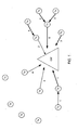
- FIG. 1 is a simple representation of a canonical radio frequency (RF) mesh network 100.
- the network illustrated in FIG. 1 includes at least one access point, which can be a gateway GW that functions as an interface between the mesh network 100 and another network, e.g., a wide-area network (not illustrated).
- the gateway GW includes a transmitter and a receiver with the capability to receive signals transmitted on at least one, but more preferably several frequencies.
- the transmitter enables the gateway to communicate with any other transceiver within a suitable signal propagation range.
- the gateway may be surrounded by a "sea" of standard single-transmitter/single-receiver transceivers, identified by the symbol "Tx" in FIG. 1 .
- the transceivers TX may represent, for example, meter nodes in a utility network and the gateway GW may provide, for example, access to various back office functions associated with the meter nodes in the utility network.
- the transceivers transmit to the gateway one at a time. These transmissions and their order are indicated by numbered lines in FIG. 1 . Solid lines indicate successfully received transmissions, either from a transceiver to the gateway or between transceiver nodes acting as relays for each other. After each successful transmission, the gateway immediately responds to the sending transceiver with an acknowledgement. Thus, when a data packet is received in time slot 1, the gateway responds with an ACK packet. Then, if another data packet is received in time slot 2, the gateway sends an ACK packet to the transceiver that transmitted that packet. The ACK packets are sent one at a time, to the individual source nodes from which they originated.
- FIG. 1 Broken lines in FIG. 1 indicate failure.
- failures can result from two sources: packet collisions and unavailability of the intended receiver.
- Packet collisions may result from two or more nodes transmitting on the same frequency and in sufficient time coincidence such that their respective packets overlap and neither transmission is received successfully at the intended receiver. This condition is illustrated by the broken lines jointly targeting the gateway in time slot 4.
- Receiver unavailability failures may happen when the intended receiver is not able to receive signals on the transmission frequency during the time required to receive a packet. This situation may arise when the intended receiver is on a different frequency engaged in receiving a packet from another node, for example in a network that employs a frequency-hopping protocol.
- the time slot 1 lines in FIG. 1 show a successful (solid line) transmission to the gateway and a failed (broken line) transmission targeted to that same receiver, which is off channel while it is communicating to the gateway.
- scheduling may be effective when the data traffic is deterministic. Scheduling may be less effective when the data traffic is unpredictable, e.g., when the data traffic is generated autonomously or reactively.
- non-adjacent nodes may occupy the same frequencies at the same time, naturally forming and enjoying frequency reuse capability.
- the serialization of packets being sent to the gateway may form a bottleneck in the RF mesh network.
- Each transceiver having a direct link to the gateway must send its message(s) at a unique time, either scheduled or uncontended, to be successfully received. After each message is received, the gateway responds before moving on to the next one.
- the gateway may be largely architecturally unique, in that it may provide access to and egress from the RF mesh network. Thus, the limits imposed by a gateway's receiver and transmitter may dominate the performance of the RF mesh network.
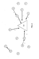
- FIG. 2 illustrates transmissions within an exemplary embodiment of a multi-channel node.
- a node e.g. a gateway
- Packets may be sent on different frequencies so that they do not collide in the frequency domain, even though they may overlap in the time domain.
- a multiplicity of messages are being received at the gateway during time slot 1.
- Non-multi-channel devices e.g., the transceiver nodes Tx shown in FIG. 2
- the transceiver nodes Tx shown in FIG. 2 are not able to receive and transmit at the same time. Therefore, transmissions directed to a simultaneously transmitting node may fail.
- the receipt of incoming data packets at the same time but on different frequencies helps to prevent frequency spectrum collisions. However, it may place any possible ACKs (back to the sending nodes) into temporal collision situations. In the embodiment of FIG. 1 , the ACKs ideally are transmitted immediately upon the receipt of the relevant data packet. However, with the multi-channel node of FIG. 2 , this may not be possible because the gateway cannot transmit while it is receiving, and vice versa.
- FIG. 3A illustrates a typical sequence for receipt of a packet and acknowledgement at a node.
- a sending node transmits a data packet containing the address of the receiving node to which the packet is addressed, as well as the sending node's address, and the data to be transmitted.
- the node to which the packet is addressed e.g., the gateway, creates an ACK packet by transposing the sender's and receiver's addresses, and adding an acknowledgement indicator.
- the receiving node then transmits the ACK packet back to the original sending node.
- FIG. 3B shows the concept of a stacked ACK packet.
- sending nodes may use, for example, the same format for a data packet as shown in FIG. 3A .
- the gateway may be configured to receive the packets transmitted by sending nodes on multiple channels at the same time, as in the embodiment of FIG. 2 .
- FIG. 3B depicts an example in which N data packets are received at the gateway.
- a single ACK packet is created.
- This packet contains a broadcast address that is recognized by all of the nodes, together with the address of the receiving node.
- the packet also contains an identifier for each of the sending nodes 1 to N from which a data packet was successfully received.
- each node looks for its identifier in the packet, and if it is found, treats the packet as an ACK packet.
- FIG. 3C shows an example of a frame structure for a stacked ACK packet.
- the frame includes a field to identify it as an ACK type of packet, which follows the broadcast address and the responding node's address.
- this frame type field may not be necessary.
- the sending node may recognize that any broadcast frame received from the destination node within a certain time period, which contains its identifier, constitutes an ACK packet.
- ACKs there may be several non-limiting ways to stack the ACKs in the responsive packet, denoted hereinafter as a "meta-ACK".
- metal-ACK There may be several non-limiting ways to stack the ACKs in the responsive packet, denoted hereinafter as a "meta-ACK”.
- Various examples are provided below:
- the response to an incoming request my take an appreciable amount of time to fulfill, which contributes to the bottleneck at a busy AP that receives such a request.
- requests include requests for updates on the executable code image of a node, requests for node routing table information, security alerts (e.g., identification of nodes whose authorization cannot be confirmed), requests for timing information (drift rates and absolute time or frequency), etc.
- these types of requests can be referred to a different node that has a better ability to handle them.
- the multi-channel AP that received the request may include a command in the set of stacked responses, instructing the source node to go to a different node for fulfillment of its request.
- the source node Upon receipt of this command, the source node then resends the request, addressed to the other node identified in the command.
- the other node to which the request is redirected may be another multi-channel receiving node that is established for the purpose of handling a distinct class of endpoint nodes. This may be the case, for example, when separate infrastructure is emplaced to support Distribution Automation (DA) nodes in a utility network.
- DA nodes have higher priority to a utility than nodes associated with meters that monitor consumption, since they are nodes that switch and control the connectivity of the power grid.
- the DA infrastructure can be kept partially 'separate' to enforce policies designed to provide faster, more reliable, or more secure communication to these DA nodes.
- stacked responses other than ACKs require a different frame format, because the response includes data that is intended for a particular source node.
- stacked responses of this type may be implemented via data packets that contain Type-Length-Value (TLV) elements.
- TLV Type-Length-Value
- optional information may be encoded as a TLV element inside the protocol.
- Each TLV element comprises the following fields:
- FIG. 3D An exemplary format for a stacked response frame that employs TLV elements is illustrated in FIG. 3D .
- the first three fields comprise the broadcast address, the address of the multi-channel node that is sending the responses, e.g. a gateway, and the frame type, in this case "TLV".
- the payload portion of the frame contains a sequence of identifiers S1, S2, ... SN for the requesting nodes, e.g., their short addresses, with each identifier immediately followed by the TLV that is intended for the corresponding node.
- the nodes check the first identifier to determine if it is theirs.
- a node If not, they examine the length field of the TLV following the identifier, which provides an offset for the next identifier in the series. This process continues, until a node recognizes its particular identifier, or reaches the end of the frame. When a node finds a match for its identifier, it examines the entire TLV element following that identifier to obtain the response that was sent to it in the stacked frame.
- the gateway can send a set of TLVs containing any type of network configuration information.
- This information may include, for example, the gateway's globally routable IPv6 prefix, the gateway's MAC address, DNS server address, routing updates, network timing information and any other variables relating to OSI model Layer 2/Layer 3 routing.
- a meta-ACK and a beacon packet.
- the information included in a classic broadcast is generally not targeted to a specific node, i.e., the information is about the transmitting node and distributed to any and all receivers within range.
- a frame format of a beacon is given below: PHY HEADER (12) Frame Control-(1) Source MAC (8) Epoch Tick TLV (4) Routing Info TLV (N) Other TLVs (N) CRC-32 (4)
- the meta-ACK similar to a beacon message, has a broadcast destination address or, more efficiently, no destination address, where the broadcast type is implicit, but the FrameType is ACK.
- the meta-ACK has a broadcast destination address or, more efficiently, no destination address, where the broadcast type is implicit, but the FrameType is ACK.
- those nodes that (1) are listening on the frequency of the meta-ACK, and (2) have recently transmitted data are interested in this meta-ACK.
- the data in the meta-ACK is thus about the data senders, and not the transmitting nodes.
- a multi-channel node can be implemented in a variety of ways. For instance, it might consist of a single transmitter and a plurality of receivers that are each tuned to a different frequency over which communications might be received. Another approach that is less hardware intensive, and therefore less expensive, can employ a digital signal processor (DSP) to differentiate multiple signals that are received simultaneously.
- DSP digital signal processor
- FIGs. 4A and 4B show an exemplary system diagram for a multi-channel node that is based on this latter implementation.
- FIG. 4A which shows an exemplary receive section of a multi-channel gateway
- multiple RF signals that are simultaneously transmitted by nodes on different channels are received at an antenna 10, and undergo suitable amplification 11 and filtering 12, 13 and 14 to segregate the signals at the desired frequencies from unwanted signals and other noise.
- the antenna 10 may be configured to receive RF signals in the unlicensed band around 900 MHz.
- the filtered signals are then converted into a digital signal in an A/D converter 15, and the resulting digital signal is supplied to a DSP 16.
- the input to the DSP 16 may include a mixture of all of the transmitted signals that were received simultaneously on the different channels.
- the DSP operates to separate this mixture into individual signals.
- the output of the DSP engine is the recovered binary data, which may be indexed and serialized for presentation to a protocol processor in an adjacent processor (not shown).
- An example of a commercially available DSP is a SPARTAN-series field-programmable gate array DSP manufactured by Xilinx, Inc. of San Jose, CA.
- the exemplary multi-channel system shown in FIG. 4A allows for processing a relatively large (multiple channel) spectrum to baseband in order to be processed by the DSP engine.
- FFT Fast Fourier Transform
- the DSP 14 uses Fast Fourier Transform (FFT) techniques to create FFT bins for each of the many channels within the down-converted spectra. In one example, there may be up to 240 channels. In an example using a carrier frequency around 900 MHz, there may be around 83 channels. These bins may act as, in effect, separate receivers for each channel.
- the received data in each channel is separately processed to determine whether it constitutes a successfully received packet. If so an ACK, or other suitable response, is prepared to be accumulated with the responses for other packets received at the same time, and returned in a meta-ACK or other similar packet containing stacked responses.
- FIG. 4B shows an exemplary multi-channel transmit section of a multi-channel gateway. Components similar to those used in the receive section of FIG. 4A can also be used in the transmit section. Additionally, digital processing software used in the receive DSP may be used in the transmit DSP. For example, the receive DSP may use FFT software while the transmit DSP may use inverse FFT software.
- multiple transmit signals may be produced by configuring the Fourier coefficients in the DSP, which will be known to a person of skill in the art of digital signal processing. For example, if the amplitude coefficient is set to 0, no energy is output on that channel or frequency. If the amplitude coefficient is set to 0.25, and three other coefficients are similarly set to 0.25, then four signals of equal strength may be produced. The amplitude coefficients may be established based on the signal energy that is estimated to be required to adequately cover a given signal path to the node targeted on the particular channel.
- FIG. 5 shows an exemplary timing sequence diagram for a multi-channel access point.
- data may be transmitted, for example, at 100 kbps, which is approximately 10 bytes/ms.
- large data packets which in this example may be 500 bytes, could take 50 ms to be transmitted; larger packets, e.g., 1500 bytes, could take 150 ms, etc.
- a second of time, i.e., 1000 ms, in an exemplary mesh network may be divided, for example, into 200 ms slots, which may be further divided into a 150 ms sub slot for inbound data to an access point and a 50 ms sub slot for outbound data from an access point.
- each second of time may include five multi-node exchange slots.
- nodes 1-4 may simultaneously communicate on separate frequencies to an access point during a 150 ms inbound sub-slot of a 200 ms slot.
- the access point may transmit a response to each communication that was successfully received from nodes 1-4 during a 50 ms outbound sub-slot.
- the response from a multi-channel access point to each of nodes 1-4 may be part of a single message sent by the access point.
- a similar sequence may continue during the other 200 ms slots.
- the multi-channel node e.g., access point, transmits a responsive packet every 200 ms. This packet contains the stacked responses, e.g., ACKs, for all inbound packets that were successfully received during the inbound sub-slot of the 200 ms slot.
- Some nodes may be delivering data to the multi-channel access point, while others that are receiving data are unable to transmit to the access point. Consequently, the nodes can be thought of as naturally forming two groups alternately delivering data and then receiving more data in a cyclic fashion.
- FIGs. 6A and 6B show examples of these packet delivery cycles.
- Frame One shows an example of packets being delivered to the AP by data-holding nodes labeled "2" that are adjacent to the AP.
- Nodes adjacent to the AP may be capable of communicating directly with the AP. These data-delivering nodes are part of Group A.
- Nodes 3 and 4 are part of Group B.
- Frame 2 shows acknowledgements being sent to the nodes that just delivered data packets.
- the AP sends an ACK, or stacked ACK, to the node or nodes 2 that sent data to the AP.
- the ACKs may be sent by the node 3 that received the data to the sending nodes 4.
- Frame 3 shows an example where data from Group B nodes is delivered to the AP while data from more remote Group A nodes 1 is delivered to nodes 2 adjacent to the AP.
- Frame 4 shows an ACK process similar to Frame 2, but in this example, the AP sends an ACK or stacked ACK to the Group B adjacent nodes 3 while for Group A, the ACKs may be sent by the nodes 2 adjacent to the AP.
- FIG. 6B is an example of the Group A and Group B packet delivery cycles in a timing sequence similar to that shown in FIG. 5 .
- FIG. 6B shows data from Group A nodes being received at the AP on multiple channels during a time sub-slot for inbound data and a subsequent ACK or stacked ACK transmission during a time sub-slot for outbound data. After the Group A time slot, a similar process occurs for the Group B nodes.
- beacon packets may be used to convey timing synchronization for the timing sequences described above.
- a beacon packet could be sent by the multi-channel nodes to indicate the times and channels at which data packets can be received and when and where the corresponding ACKs will be sent.
- These beacon packets may be sent at pre-specified times and may be available to all nodes within direct range of the multiple-channel receiving node, e.g., the nodes immediately adjacent to the multi-channel nodes.
- the failure of the sender of the request to receive the ACK may result in the request being re-sent.
- This additional request may be managed by the multi-channel receiving node by sending an ACK again, but not passing along any request in the re-sent packet to a target node.
- a target node may operate to drop the duplicate request when forwarded by the multi-channel receiving node.
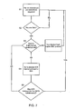
- FIG. 7 shows an exemplary process flow diagram for a mesh network with multi-channel access points.
- a node listens to a pre-determined channel at a pre-determined time according to a sequence conveyed to the node by a beacon packet, for example.
- step S2 if no data is received, the node returns to following the pre-determined channel and timing sequence.
- step S3 the node determines whether it is to forward the received data to a single channel or multi-channel node. If the determination is not to forward the data to a multi-channel node, the data may be sent using a standard half-duplex MAC protocol, for example.
- step S4 if the data is to be sent to a multi-channel node, once the data is transmitted, the sending node may then go to a pre-determined stacked ACK channel to wait for its particular ACK.
- the channel and timing for receiving stacked ACKs may be conveyed by beacon packets.
- step S5 the original sending node determines whether an ACK was received for a particular data transmission. If an ACK is received, the process may return to step S1 and proceed as described above. If an ACK is not received, the process may return to step S3 where the node may re-send the data to the multi-channel node and then proceed to step S4 to listen for an ACK.
- the AP may send only one packet at a time, but there may be no limitation on the number of packets it can receive simultaneously.
- any node may send a packet on any channel on which the AP may receive, which in another example is all the channels capable of being used in a particular system.
- the examples described herein may lessen the impact of limitations of known systems, e.g., the availability of hardware/software in the inbound direction, to receive a packet.
- the AP may receive packets within radio propagation range, check them for correctness and build a response packet - an ACK.
- received packets are acknowledged, unless explicitly requested not to.
- Another example may include ordering the acknowledgement data by some priority or other scheme that, by its order conveys information or adds efficiency.
- This meta-packet may be sent on a known slot, i.e., a frequency/time couplet, and may serve to complete a multi-packet handshake of a standard packet exchange.
Claims (14)
- Verfahren zum Kommunizieren in einem Netzwerk, wobei das Verfahren Folgendes umfasst:Empfangen (S1), durch einen zweiten Knoten, von Kommunikationen von jedem aus einer Mehrzahl erster Knoten auf mehreren jeweiligen Kanälen, undSenden (S3), durch den zweiten Knoten, einer Übertragung, die eine Antwort (ACK) auf jede Kommunikation enthält, die erfolgreich von jedem der Mehrzahl von ersten Knoten kommend empfangen wurde, wobei die Antwort (ACK) auf jede der Mehrzahl von ersten Knoten Teil einer einzelnen Nachricht ist, die durch den zweiten Knoten gesendet wurde,dadurch gekennzeichnet, dass die ersten Knoten in mindestens zwei Gruppen (Gruppe A, Gruppe B) unterteilt sind und dass in einer ersten Gruppe (Gruppe A) erste Knoten neben dem zweiten Knoten direkt mit dem zweiten Knoten kommunizieren, während in einer zweiten Gruppe (Gruppe B) erste Knoten neben dem zweiten Knoten mit anderen ersten Knoten kommunizieren, und dass, sobald die erste Gruppe (Gruppe A) das Kommunizieren mit dem zweiten Knoten vollendet hat, in der zweiten Gruppe (Gruppe B) erste Knoten neben dem zweiten Knoten direkt mit dem zweiten Knoten kommunizieren, während in der ersten Gruppe (Gruppe A) erste Knoten neben dem zweiten Knoten mit anderen ersten Knoten kommunizieren.
- Verfahren nach Anspruch 1, wobei die Nachricht, die durch den zweiten Knoten gesendet wurde, Identifizierer umfasst, die jeweils jedem der Mehrzahl von ersten Knoten entsprechen, dessen Kommunikation erfolgreich durch den zweiten Knoten empfangen wurde.
- Verfahren nach Anspruch 1, wobei jede Antwort von dem zweiten Knoten an die Mehrzahl von ersten Knoten in der Übertragung anhand einer Priorität geordnet wird, die mit dem Inhalt eines empfangenen Paketes verknüpft ist.
- Verfahren nach Anspruch 3, wobei jede Antwort von dem zweiten Knoten an die Mehrzahl von ersten Knoten in der Übertragung anhand einer Priorität geordnet wird, die mit dem Knoten verknüpft ist, von dem ein Paket empfangen wurde.
- Verfahren nach Anspruch 1, wobei die Kommunikation eine Aufforderung umfasst, durch mindestens einen der ersten Knoten gesendet wird, und wobei die Antwort einen Befehl umfasst, der den mindestens einen ersten Knoten anweist, die Aufforderung an einen anderen Knoten zu senden.
- Verfahren nach Anspruch 1, wobei das Senden der Kommunikation durch jeden der Mehrzahl von ersten Knoten und das Senden der Übertragung durch den zweiten Knoten während eines zuvor festgelegten Zeitschlitzes stattfindet.
- Verfahren nach Anspruch 6, wobei Informationen über den zuvor festgelegten Zeitschlitz an die ersten Knoten in Beacon-Paketen gesendet werden.
- Verfahren nach Anspruch 1, wobei die Informationen Netzwerkzeitsteuerungsinformationen enthalten.
- Verfahren nach Anspruch 1, wobei die Informationen mindestens eine Variable enthalten, die sich auf den Betrieb des mindestens einen ersten Knotens in Network Protocol Layer 2 und/oder Layer 3 bezieht.
- Verfahren nach Anspruch 1, wobei die Informationen einen Befehl an den mindestens einen ersten Knoten enthalten, der den mindestens einen ersten Knoten anweist, eine bestimmte durch den Befehl dargestellte Operation auszuführen.
- Verfahren nach Anspruch 1, wobei die bestimmte Operation eine Operation für den mindestens einen ersten Knoten ist, die Sendung der Kommunikation an einen anderen Knoten als den zweiten Knoten zu wiederholen.
- Verfahren nach Anspruch 1 oder 10, wobei die Informationen innerhalb mindestens eines Type-Length-Value (TLV)-Elements innerhalb der einzelnen Nachrichtantwort codiert sind.
- Verfahren nach Anspruch 12, wobei jedes TLV-Element einem separaten jeweiligen der ersten Knoten entspricht.
- Verfahren nach Anspruch 13, wobei ein Typ-Feld jedes TLV-Elements anzeigt, welchem der separaten jeweiligen der ersten Knoten das TLV-Element entspricht.
Applications Claiming Priority (2)
| Application Number | Priority Date | Filing Date | Title |
|---|---|---|---|
| US12/207,358 US9025584B2 (en) | 2008-09-09 | 2008-09-09 | Multi-channel mesh nodes employing stacked responses |
| PCT/US2009/004855 WO2010030322A2 (en) | 2008-09-09 | 2009-08-26 | Multi-channel mesh nodes employing stacked responses |
Publications (2)
| Publication Number | Publication Date |
|---|---|
| EP2324590A2 EP2324590A2 (de) | 2011-05-25 |
| EP2324590B1 true EP2324590B1 (de) | 2014-11-12 |
Family
ID=41799225
Family Applications (1)
| Application Number | Title | Priority Date | Filing Date |
|---|---|---|---|
| EP09789211.1A Active EP2324590B1 (de) | 2008-09-09 | 2009-08-26 | Mehrkanal-mesh-knoten, die gestapelte antworten verwenden |
Country Status (13)
| Country | Link |
|---|---|
| US (3) | US9025584B2 (de) |
| EP (1) | EP2324590B1 (de) |
| JP (1) | JP5587888B2 (de) |
| KR (1) | KR20110063666A (de) |
| CN (1) | CN102204145A (de) |
| AR (1) | AR073502A1 (de) |
| AU (1) | AU2009292221A1 (de) |
| BR (1) | BRPI0919101A2 (de) |
| CA (1) | CA2736737A1 (de) |
| DK (1) | DK2324590T3 (de) |
| MX (1) | MX2011002569A (de) |
| TW (1) | TW201012251A (de) |
| WO (1) | WO2010030322A2 (de) |
Families Citing this family (40)
| Publication number | Priority date | Publication date | Assignee | Title |
|---|---|---|---|---|
| EP2203911A4 (de) | 2007-10-25 | 2011-12-28 | Trilliant Networks Inc | Gasmesser mit nachgerüstetem ultrasensitivem magnetmaterial auf der messskala und nachrüstungsverfahren für die messskala |
| US8138934B2 (en) | 2007-11-25 | 2012-03-20 | Trilliant Networks, Inc. | System and method for false alert filtering of event messages within a network |
| EP2215556B1 (de) | 2007-11-25 | 2019-08-28 | Trilliant Networks, Inc. | System und verfahren für stromzustandübertragung in einem ami-system |
| EP2215550A1 (de) | 2007-11-25 | 2010-08-11 | Trilliant Networks, Inc. | System und verfahren zur steuerung des energieverbrauchs |
| WO2009067259A1 (en) | 2007-11-25 | 2009-05-28 | Trilliant Networks, Inc. | Transport layer and model for an advanced metering infrastructure (ami) network |
| US8699377B2 (en) | 2008-09-04 | 2014-04-15 | Trilliant Networks, Inc. | System and method for implementing mesh network communications using a mesh network protocol |
| US8457106B2 (en) * | 2008-09-30 | 2013-06-04 | Electronics And Telecommunications Research Institute | Method for wireless communication in wireless sensor network environment |
| US8289182B2 (en) | 2008-11-21 | 2012-10-16 | Trilliant Networks, Inc. | Methods and systems for virtual energy management display |
| US8319658B2 (en) | 2009-03-11 | 2012-11-27 | Trilliant Networks, Inc. | Process, device and system for mapping transformers to meters and locating non-technical line losses |
| MX2011009052A (es) * | 2009-05-07 | 2012-02-28 | Dominion Resources Inc | Conservacion de voltaje usando infraestructura de medicion avanzada y control de voltaje centralizado en la subestacion. |
| WO2012027634A1 (en) | 2010-08-27 | 2012-03-01 | Trilliant Networkd, Inc. | System and method for interference free operation of co-located tranceivers |
| WO2012037055A1 (en) | 2010-09-13 | 2012-03-22 | Trilliant Networks | Process for detecting energy theft |
| EP2641137A2 (de) | 2010-11-15 | 2013-09-25 | Trilliant Holdings, Inc. | System und verfahren zur sicheren kommunikation in mehreren netzwerken mittels einzelfunk |
| JP5604314B2 (ja) * | 2011-01-13 | 2014-10-08 | オムロンオートモーティブエレクトロニクス株式会社 | 電波送受体の検出装置、検出システム及び検出方法 |
| WO2012097204A1 (en) | 2011-01-14 | 2012-07-19 | Trilliant Holdings, Inc. | Process, device and system for volt/var optimization |
| WO2012103072A2 (en) | 2011-01-25 | 2012-08-02 | Trilliant Holdings, Inc. | Aggregated real-time power outages/restoration reporting (rtpor) in a secure mesh network |
| US9319184B2 (en) * | 2011-02-01 | 2016-04-19 | Qualcomm Incorporated | Multiple wireless communication device acknowledgements |
| EP3285458B1 (de) | 2011-02-10 | 2022-10-26 | Trilliant Holdings, Inc. | Vorrichtung und verfahren zur bereitstellung sicherer kommunikationen über ein zellulares netzwerk |
| WO2012122310A1 (en) | 2011-03-08 | 2012-09-13 | Trilliant Networks, Inc. | System and method for managing load distribution across a power grid |
| US9300442B2 (en) | 2011-07-21 | 2016-03-29 | Qualcomm Incorporated | Allowing a rejected wireless communication device access to a communication channel |
| US9083590B2 (en) * | 2011-08-15 | 2015-07-14 | Marvell World Trade Ltd | Long range WLAN data unit format |
| US9001787B1 (en) | 2011-09-20 | 2015-04-07 | Trilliant Networks Inc. | System and method for implementing handover of a hybrid communications module |
| CN106850140B (zh) * | 2012-01-12 | 2020-04-28 | 华为终端有限公司 | 数据通信的方法、装置及系统 |
| US9584179B2 (en) * | 2012-02-23 | 2017-02-28 | Silver Spring Networks, Inc. | System and method for multi-channel frequency hopping spread spectrum communication |
| US9582020B2 (en) | 2013-03-15 | 2017-02-28 | Dominion Resources, Inc. | Maximizing of energy delivery system compatibility with voltage optimization using AMI-based data control and analysis |
| US9553453B2 (en) | 2013-03-15 | 2017-01-24 | Dominion Resources, Inc. | Management of energy demand and energy efficiency savings from voltage optimization on electric power systems using AMI-based data analysis |
| US9847639B2 (en) | 2013-03-15 | 2017-12-19 | Dominion Energy, Inc. | Electric power system control with measurement of energy demand and energy efficiency |
| US9678520B2 (en) | 2013-03-15 | 2017-06-13 | Dominion Resources, Inc. | Electric power system control with planning of energy demand and energy efficiency using AMI-based data analysis |
| US9563218B2 (en) | 2013-03-15 | 2017-02-07 | Dominion Resources, Inc. | Electric power system control with measurement of energy demand and energy efficiency using t-distributions |
| CN104378828B (zh) * | 2013-08-15 | 2018-03-09 | 华为技术有限公司 | 一种信道接入的方法、装置和系统 |
| KR101484059B1 (ko) | 2013-09-17 | 2015-01-20 | 성균관대학교산학협력단 | 다중 전송 속도 파티셔닝 및 협력 전송을 이용한 고속 무선랜 통신 방법 및 무선랜 통신 장치 |
| US10263892B2 (en) | 2015-03-20 | 2019-04-16 | Microchip Technology Incorporated | Compression method and system for user friendly address in mesh networking |
| EP3098793A1 (de) | 2015-05-26 | 2016-11-30 | Life Safety Distribution AG | Verfahren zur konfiguration eines drahtlosen feuerdetektionssystems |
| EP3311607A4 (de) * | 2015-06-22 | 2018-12-26 | DNG Technologies Ltd | Smart-home-system |
| US10015239B1 (en) | 2015-08-12 | 2018-07-03 | Evengx, Llc | Self-organizing distributed computation grid |
| US10732656B2 (en) | 2015-08-24 | 2020-08-04 | Dominion Energy, Inc. | Systems and methods for stabilizer control |
| CN107872300B (zh) | 2016-09-28 | 2022-11-04 | 中兴通讯股份有限公司 | 反馈信息处理方法、装置及系统、基站、终端 |
| CN108347321A (zh) * | 2017-01-25 | 2018-07-31 | 华为技术有限公司 | 一种通信方法及装置 |
| CN107404377B (zh) * | 2017-09-11 | 2020-10-27 | 海能达通信股份有限公司 | 一种接入信号生成方法、装置及接入信号 |
| CN111279644B (zh) | 2017-10-27 | 2022-08-09 | 瑞典爱立信有限公司 | 用于更新无线网格网络中重传次数的方法和设备 |
Family Cites Families (15)
| Publication number | Priority date | Publication date | Assignee | Title |
|---|---|---|---|---|
| JP4037965B2 (ja) | 1998-08-18 | 2008-01-23 | 富士通株式会社 | 符号分割多元接続通信システム並びに符号分割多元接続通信システム用基地局及び符号分割多元接続通信システム用端末装置並びに符号分割多元接続通信方法並びに端末装置の通信方法 |
| US20050058149A1 (en) * | 1998-08-19 | 2005-03-17 | Howe Wayne Richard | Time-scheduled and time-reservation packet switching |
| US6338092B1 (en) | 1998-09-24 | 2002-01-08 | International Business Machines Corporation | Method, system and computer program for replicating data in a distributed computed environment |
| US7310670B1 (en) | 2000-04-25 | 2007-12-18 | Thomson Licensing S.A. | Multi-channel power line exchange protocol |
| US7469297B1 (en) * | 2000-08-04 | 2008-12-23 | Intellon Corporation | Mechanism for using a quasi-addressed response to bind to a message requesting the response |
| US7464166B2 (en) * | 2003-04-11 | 2008-12-09 | Telefonaktiebolaget Lm Ericsson (Publ) | Contention-based forwarding with integrated multi-user detection capability |
| US7230951B2 (en) * | 2003-04-16 | 2007-06-12 | Nortel Networks Limited | Policy based mobile IP |
| JP4710321B2 (ja) * | 2004-02-02 | 2011-06-29 | ソニー株式会社 | 無線通信システム、無線通信装置及び無線通信方法、並びにコンピュータ・プログラム |
| TWI261441B (en) | 2004-06-28 | 2006-09-01 | Nokia Corp | Method and apparatus for packet aggregation in a wireless communication network |
| US7466964B2 (en) | 2005-06-29 | 2008-12-16 | Intel Corporation | Wireless communication device and method for coordinated channel access with reduced latency in a wireless network |
| JP2007129726A (ja) | 2005-11-04 | 2007-05-24 | Samsung Electronics Co Ltd | マルチホップ中継方式のセルラーネットワークでマルチホップをグループ化してマルチリンクを支援するための装置及び方法 |
| US7577449B2 (en) * | 2006-06-29 | 2009-08-18 | Motorola, Inc. | Method and system for coordinating a sleep mode wake-up time |
| JP4790544B2 (ja) | 2006-08-31 | 2011-10-12 | 富士通株式会社 | リレー通信システムにおける再送制御方法及びリレー局装置 |
| US20080068979A1 (en) | 2006-09-14 | 2008-03-20 | Motorola, Inc. | Adaptive and preemptive scheduling of transmissions |
| US8027356B2 (en) * | 2008-01-31 | 2011-09-27 | Lg Electronics Inc. | Method for signaling back-off information in random access |
-
2008
- 2008-09-09 US US12/207,358 patent/US9025584B2/en active Active
-
2009
- 2009-08-26 MX MX2011002569A patent/MX2011002569A/es not_active Application Discontinuation
- 2009-08-26 KR KR1020117008218A patent/KR20110063666A/ko not_active Application Discontinuation
- 2009-08-26 JP JP2011526034A patent/JP5587888B2/ja active Active
- 2009-08-26 CN CN2009801421359A patent/CN102204145A/zh active Pending
- 2009-08-26 AU AU2009292221A patent/AU2009292221A1/en not_active Abandoned
- 2009-08-26 DK DK09789211.1T patent/DK2324590T3/da active
- 2009-08-26 EP EP09789211.1A patent/EP2324590B1/de active Active
- 2009-08-26 CA CA2736737A patent/CA2736737A1/en not_active Abandoned
- 2009-08-26 BR BRPI0919101A patent/BRPI0919101A2/pt not_active IP Right Cessation
- 2009-08-26 WO PCT/US2009/004855 patent/WO2010030322A2/en active Application Filing
- 2009-09-08 AR ARP090103443A patent/AR073502A1/es unknown
- 2009-09-08 TW TW098130211A patent/TW201012251A/zh unknown
-
2015
- 2015-04-10 US US14/683,206 patent/US9288712B2/en active Active
-
2016
- 2016-02-12 US US15/042,633 patent/US9838902B2/en active Active
Also Published As
| Publication number | Publication date |
|---|---|
| MX2011002569A (es) | 2011-04-07 |
| CA2736737A1 (en) | 2010-03-18 |
| WO2010030322A3 (en) | 2010-07-08 |
| EP2324590A2 (de) | 2011-05-25 |
| US20100061350A1 (en) | 2010-03-11 |
| KR20110063666A (ko) | 2011-06-13 |
| WO2010030322A2 (en) | 2010-03-18 |
| AU2009292221A2 (en) | 2011-05-26 |
| US20160165479A1 (en) | 2016-06-09 |
| AR073502A1 (es) | 2010-11-10 |
| AU2009292221A1 (en) | 2010-03-18 |
| US9025584B2 (en) | 2015-05-05 |
| JP5587888B2 (ja) | 2014-09-10 |
| US9288712B2 (en) | 2016-03-15 |
| BRPI0919101A2 (pt) | 2019-09-24 |
| JP2012502551A (ja) | 2012-01-26 |
| US20150215813A1 (en) | 2015-07-30 |
| TW201012251A (en) | 2010-03-16 |
| US9838902B2 (en) | 2017-12-05 |
| DK2324590T3 (da) | 2015-01-05 |
| CN102204145A (zh) | 2011-09-28 |
Similar Documents
| Publication | Publication Date | Title |
|---|---|---|
| US9838902B2 (en) | Multi-channel mesh nodes employing stacked responses | |
| JP7443345B2 (ja) | 通信技法 | |
| US8514861B2 (en) | Apparatus and method for multicasting data in a communication network | |
| US20030227934A1 (en) | System and method for multicast media access using broadcast transmissions with multiple acknowledgements in an Ad-Hoc communications network | |
| JP5265014B2 (ja) | 超高信頼性の協調無線通信 | |
| US20110235596A1 (en) | Uplink sdma transmit opportunity scheduling | |
| US20080170544A1 (en) | Method of transmitting between two nodes | |
| US8897221B2 (en) | Communication system, communication apparatus, communication method, and computer program | |
| TW202030998A (zh) | 超高輸送量多頻帶傳輸 | |
| US20210385821A1 (en) | Method and device for transmitting and receiving sidelink signal in wireless communication system | |
| US20200029376A1 (en) | Selective retransmission procedure | |
| WO2007008174A1 (en) | Method and system of wireless communication between devices | |
| EP2386149B1 (de) | Methode und system zur kommunikation in einem drahtlosen netzwerk | |
| US20210112384A1 (en) | Device and method for v2x communication | |
| Campolo et al. | Improving V2R connectivity to provide ITS applications in IEEE 802.11 p/WAVE VANETs | |
| Uemura | An efficient multicasting method without a base station | |
| JP2016111396A (ja) | 無線通信装置 |
Legal Events
| Date | Code | Title | Description |
|---|---|---|---|
| PUAI | Public reference made under article 153(3) epc to a published international application that has entered the european phase |
Free format text: ORIGINAL CODE: 0009012 |
|
| 17P | Request for examination filed |
Effective date: 20110315 |
|
| AK | Designated contracting states |
Kind code of ref document: A2 Designated state(s): AT BE BG CH CY CZ DE DK EE ES FI FR GB GR HR HU IE IS IT LI LT LU LV MC MK MT NL NO PL PT RO SE SI SK SM TR |
|
| AX | Request for extension of the european patent |
Extension state: AL BA RS |
|
| DAX | Request for extension of the european patent (deleted) | ||
| 17Q | First examination report despatched |
Effective date: 20111213 |
|
| GRAP | Despatch of communication of intention to grant a patent |
Free format text: ORIGINAL CODE: EPIDOSNIGR1 |
|
| INTG | Intention to grant announced |
Effective date: 20140519 |
|
| GRAS | Grant fee paid |
Free format text: ORIGINAL CODE: EPIDOSNIGR3 |
|
| GRAA | (expected) grant |
Free format text: ORIGINAL CODE: 0009210 |
|
| AK | Designated contracting states |
Kind code of ref document: B1 Designated state(s): AT BE BG CH CY CZ DE DK EE ES FI FR GB GR HR HU IE IS IT LI LT LU LV MC MK MT NL NO PL PT RO SE SI SK SM TR |
|
| REG | Reference to a national code |
Ref country code: GB Ref legal event code: FG4D |
|
| REG | Reference to a national code |
Ref country code: CH Ref legal event code: EP |
|
| REG | Reference to a national code |
Ref country code: AT Ref legal event code: REF Ref document number: 696312 Country of ref document: AT Kind code of ref document: T Effective date: 20141115 |
|
| REG | Reference to a national code |
Ref country code: IE Ref legal event code: FG4D |
|
| REG | Reference to a national code |
Ref country code: DE Ref legal event code: R096 Ref document number: 602009027742 Country of ref document: DE Effective date: 20141224 |
|
| REG | Reference to a national code |
Ref country code: DK Ref legal event code: T3 Effective date: 20141217 |
|
| REG | Reference to a national code |
Ref country code: NL Ref legal event code: VDEP Effective date: 20141112 |
|
| REG | Reference to a national code |
Ref country code: AT Ref legal event code: MK05 Ref document number: 696312 Country of ref document: AT Kind code of ref document: T Effective date: 20141112 |
|
| PG25 | Lapsed in a contracting state [announced via postgrant information from national office to epo] |
Ref country code: LT Free format text: LAPSE BECAUSE OF FAILURE TO SUBMIT A TRANSLATION OF THE DESCRIPTION OR TO PAY THE FEE WITHIN THE PRESCRIBED TIME-LIMIT Effective date: 20141112 Ref country code: IS Free format text: LAPSE BECAUSE OF FAILURE TO SUBMIT A TRANSLATION OF THE DESCRIPTION OR TO PAY THE FEE WITHIN THE PRESCRIBED TIME-LIMIT Effective date: 20150312 Ref country code: ES Free format text: LAPSE BECAUSE OF FAILURE TO SUBMIT A TRANSLATION OF THE DESCRIPTION OR TO PAY THE FEE WITHIN THE PRESCRIBED TIME-LIMIT Effective date: 20141112 Ref country code: FI Free format text: LAPSE BECAUSE OF FAILURE TO SUBMIT A TRANSLATION OF THE DESCRIPTION OR TO PAY THE FEE WITHIN THE PRESCRIBED TIME-LIMIT Effective date: 20141112 Ref country code: PT Free format text: LAPSE BECAUSE OF FAILURE TO SUBMIT A TRANSLATION OF THE DESCRIPTION OR TO PAY THE FEE WITHIN THE PRESCRIBED TIME-LIMIT Effective date: 20150312 Ref country code: NO Free format text: LAPSE BECAUSE OF FAILURE TO SUBMIT A TRANSLATION OF THE DESCRIPTION OR TO PAY THE FEE WITHIN THE PRESCRIBED TIME-LIMIT Effective date: 20150212 Ref country code: NL Free format text: LAPSE BECAUSE OF FAILURE TO SUBMIT A TRANSLATION OF THE DESCRIPTION OR TO PAY THE FEE WITHIN THE PRESCRIBED TIME-LIMIT Effective date: 20141112 |
|
| PG25 | Lapsed in a contracting state [announced via postgrant information from national office to epo] |
Ref country code: LV Free format text: LAPSE BECAUSE OF FAILURE TO SUBMIT A TRANSLATION OF THE DESCRIPTION OR TO PAY THE FEE WITHIN THE PRESCRIBED TIME-LIMIT Effective date: 20141112 Ref country code: SE Free format text: LAPSE BECAUSE OF FAILURE TO SUBMIT A TRANSLATION OF THE DESCRIPTION OR TO PAY THE FEE WITHIN THE PRESCRIBED TIME-LIMIT Effective date: 20141112 Ref country code: HR Free format text: LAPSE BECAUSE OF FAILURE TO SUBMIT A TRANSLATION OF THE DESCRIPTION OR TO PAY THE FEE WITHIN THE PRESCRIBED TIME-LIMIT Effective date: 20141112 Ref country code: AT Free format text: LAPSE BECAUSE OF FAILURE TO SUBMIT A TRANSLATION OF THE DESCRIPTION OR TO PAY THE FEE WITHIN THE PRESCRIBED TIME-LIMIT Effective date: 20141112 Ref country code: CY Free format text: LAPSE BECAUSE OF FAILURE TO SUBMIT A TRANSLATION OF THE DESCRIPTION OR TO PAY THE FEE WITHIN THE PRESCRIBED TIME-LIMIT Effective date: 20141112 Ref country code: PL Free format text: LAPSE BECAUSE OF FAILURE TO SUBMIT A TRANSLATION OF THE DESCRIPTION OR TO PAY THE FEE WITHIN THE PRESCRIBED TIME-LIMIT Effective date: 20141112 Ref country code: GR Free format text: LAPSE BECAUSE OF FAILURE TO SUBMIT A TRANSLATION OF THE DESCRIPTION OR TO PAY THE FEE WITHIN THE PRESCRIBED TIME-LIMIT Effective date: 20150213 |
|
| PG25 | Lapsed in a contracting state [announced via postgrant information from national office to epo] |
Ref country code: EE Free format text: LAPSE BECAUSE OF FAILURE TO SUBMIT A TRANSLATION OF THE DESCRIPTION OR TO PAY THE FEE WITHIN THE PRESCRIBED TIME-LIMIT Effective date: 20141112 Ref country code: CZ Free format text: LAPSE BECAUSE OF FAILURE TO SUBMIT A TRANSLATION OF THE DESCRIPTION OR TO PAY THE FEE WITHIN THE PRESCRIBED TIME-LIMIT Effective date: 20141112 Ref country code: RO Free format text: LAPSE BECAUSE OF FAILURE TO SUBMIT A TRANSLATION OF THE DESCRIPTION OR TO PAY THE FEE WITHIN THE PRESCRIBED TIME-LIMIT Effective date: 20141112 Ref country code: SK Free format text: LAPSE BECAUSE OF FAILURE TO SUBMIT A TRANSLATION OF THE DESCRIPTION OR TO PAY THE FEE WITHIN THE PRESCRIBED TIME-LIMIT Effective date: 20141112 |
|
| REG | Reference to a national code |
Ref country code: DE Ref legal event code: R097 Ref document number: 602009027742 Country of ref document: DE |
|
| PLBE | No opposition filed within time limit |
Free format text: ORIGINAL CODE: 0009261 |
|
| STAA | Information on the status of an ep patent application or granted ep patent |
Free format text: STATUS: NO OPPOSITION FILED WITHIN TIME LIMIT |
|
| 26N | No opposition filed |
Effective date: 20150813 |
|
| PG25 | Lapsed in a contracting state [announced via postgrant information from national office to epo] |
Ref country code: IT Free format text: LAPSE BECAUSE OF FAILURE TO SUBMIT A TRANSLATION OF THE DESCRIPTION OR TO PAY THE FEE WITHIN THE PRESCRIBED TIME-LIMIT Effective date: 20141112 |
|
| PG25 | Lapsed in a contracting state [announced via postgrant information from national office to epo] |
Ref country code: SI Free format text: LAPSE BECAUSE OF FAILURE TO SUBMIT A TRANSLATION OF THE DESCRIPTION OR TO PAY THE FEE WITHIN THE PRESCRIBED TIME-LIMIT Effective date: 20141112 |
|
| PG25 | Lapsed in a contracting state [announced via postgrant information from national office to epo] |
Ref country code: MC Free format text: LAPSE BECAUSE OF FAILURE TO SUBMIT A TRANSLATION OF THE DESCRIPTION OR TO PAY THE FEE WITHIN THE PRESCRIBED TIME-LIMIT Effective date: 20141112 Ref country code: LU Free format text: LAPSE BECAUSE OF FAILURE TO SUBMIT A TRANSLATION OF THE DESCRIPTION OR TO PAY THE FEE WITHIN THE PRESCRIBED TIME-LIMIT Effective date: 20150826 |
|
| REG | Reference to a national code |
Ref country code: CH Ref legal event code: PL |
|
| PG25 | Lapsed in a contracting state [announced via postgrant information from national office to epo] |
Ref country code: LI Free format text: LAPSE BECAUSE OF NON-PAYMENT OF DUE FEES Effective date: 20150831 Ref country code: CH Free format text: LAPSE BECAUSE OF NON-PAYMENT OF DUE FEES Effective date: 20150831 |
|
| REG | Reference to a national code |
Ref country code: IE Ref legal event code: MM4A |
|
| PG25 | Lapsed in a contracting state [announced via postgrant information from national office to epo] |
Ref country code: IE Free format text: LAPSE BECAUSE OF NON-PAYMENT OF DUE FEES Effective date: 20150826 |
|
| REG | Reference to a national code |
Ref country code: FR Ref legal event code: PLFP Year of fee payment: 8 |
|
| PG25 | Lapsed in a contracting state [announced via postgrant information from national office to epo] |
Ref country code: MT Free format text: LAPSE BECAUSE OF FAILURE TO SUBMIT A TRANSLATION OF THE DESCRIPTION OR TO PAY THE FEE WITHIN THE PRESCRIBED TIME-LIMIT Effective date: 20141112 |
|
| PG25 | Lapsed in a contracting state [announced via postgrant information from national office to epo] |
Ref country code: BG Free format text: LAPSE BECAUSE OF FAILURE TO SUBMIT A TRANSLATION OF THE DESCRIPTION OR TO PAY THE FEE WITHIN THE PRESCRIBED TIME-LIMIT Effective date: 20141112 Ref country code: HU Free format text: LAPSE BECAUSE OF FAILURE TO SUBMIT A TRANSLATION OF THE DESCRIPTION OR TO PAY THE FEE WITHIN THE PRESCRIBED TIME-LIMIT; INVALID AB INITIO Effective date: 20090826 Ref country code: SM Free format text: LAPSE BECAUSE OF FAILURE TO SUBMIT A TRANSLATION OF THE DESCRIPTION OR TO PAY THE FEE WITHIN THE PRESCRIBED TIME-LIMIT Effective date: 20141112 |
|
| REG | Reference to a national code |
Ref country code: FR Ref legal event code: PLFP Year of fee payment: 9 |
|
| PG25 | Lapsed in a contracting state [announced via postgrant information from national office to epo] |
Ref country code: TR Free format text: LAPSE BECAUSE OF FAILURE TO SUBMIT A TRANSLATION OF THE DESCRIPTION OR TO PAY THE FEE WITHIN THE PRESCRIBED TIME-LIMIT Effective date: 20141112 |
|
| PG25 | Lapsed in a contracting state [announced via postgrant information from national office to epo] |
Ref country code: BE Free format text: LAPSE BECAUSE OF FAILURE TO SUBMIT A TRANSLATION OF THE DESCRIPTION OR TO PAY THE FEE WITHIN THE PRESCRIBED TIME-LIMIT Effective date: 20141112 |
|
| PG25 | Lapsed in a contracting state [announced via postgrant information from national office to epo] |
Ref country code: MK Free format text: LAPSE BECAUSE OF FAILURE TO SUBMIT A TRANSLATION OF THE DESCRIPTION OR TO PAY THE FEE WITHIN THE PRESCRIBED TIME-LIMIT Effective date: 20141112 |
|
| REG | Reference to a national code |
Ref country code: FR Ref legal event code: PLFP Year of fee payment: 10 |
|
| REG | Reference to a national code |
Ref country code: DE Ref legal event code: R081 Ref document number: 602009027742 Country of ref document: DE Owner name: ITRON NETWORKED SOLUTIONS, INC. (N.D.GES.D. ST, US Free format text: FORMER OWNER: SILVER SPRING NETWORKS, INC., REDWOOD CITY, CALIF., US |
|
| P01 | Opt-out of the competence of the unified patent court (upc) registered |
Effective date: 20230519 |
|
| PGFP | Annual fee paid to national office [announced via postgrant information from national office to epo] |
Ref country code: DK Payment date: 20230627 Year of fee payment: 15 |
|
| PGFP | Annual fee paid to national office [announced via postgrant information from national office to epo] |
Ref country code: GB Payment date: 20230706 Year of fee payment: 15 |
|
| PGFP | Annual fee paid to national office [announced via postgrant information from national office to epo] |
Ref country code: FR Payment date: 20230703 Year of fee payment: 15 Ref country code: DE Payment date: 20230703 Year of fee payment: 15 |