EP2323829B1 - Process for fastening an accessory to a plastic hollow body - Google Patents
Process for fastening an accessory to a plastic hollow body Download PDFInfo
- Publication number
- EP2323829B1 EP2323829B1 EP09804576A EP09804576A EP2323829B1 EP 2323829 B1 EP2323829 B1 EP 2323829B1 EP 09804576 A EP09804576 A EP 09804576A EP 09804576 A EP09804576 A EP 09804576A EP 2323829 B1 EP2323829 B1 EP 2323829B1
- Authority
- EP
- European Patent Office
- Prior art keywords
- parison
- accessory
- snap
- riveting
- cavities
- Prior art date
- Legal status (The legal status is an assumption and is not a legal conclusion. Google has not performed a legal analysis and makes no representation as to the accuracy of the status listed.)
- Active
Links
- 238000000034 method Methods 0.000 title claims description 29
- 230000008569 process Effects 0.000 title claims description 25
- 239000004033 plastic Substances 0.000 title claims description 13
- 229920003023 plastic Polymers 0.000 title claims description 13
- 238000000465 moulding Methods 0.000 claims description 19
- 238000003466 welding Methods 0.000 claims description 14
- 238000000071 blow moulding Methods 0.000 claims description 5
- 238000003856 thermoforming Methods 0.000 claims description 3
- 238000007664 blowing Methods 0.000 claims description 2
- 239000002828 fuel tank Substances 0.000 description 15
- 239000000463 material Substances 0.000 description 10
- 229920001577 copolymer Polymers 0.000 description 7
- 229920001169 thermoplastic Polymers 0.000 description 7
- 239000000446 fuel Substances 0.000 description 6
- 239000007789 gas Substances 0.000 description 5
- 229920000642 polymer Polymers 0.000 description 5
- 239000004416 thermosoftening plastic Substances 0.000 description 5
- 230000004888 barrier function Effects 0.000 description 4
- 238000001125 extrusion Methods 0.000 description 4
- 239000007788 liquid Substances 0.000 description 4
- 229920005989 resin Polymers 0.000 description 4
- 239000011347 resin Substances 0.000 description 4
- 230000000295 complement effect Effects 0.000 description 3
- 229920001903 high density polyethylene Polymers 0.000 description 3
- 239000004700 high-density polyethylene Substances 0.000 description 3
- 238000011065 in-situ storage Methods 0.000 description 3
- 238000004519 manufacturing process Methods 0.000 description 3
- 239000000203 mixture Substances 0.000 description 3
- 229920000219 Ethylene vinyl alcohol Polymers 0.000 description 2
- XSQUKJJJFZCRTK-UHFFFAOYSA-N Urea Chemical compound NC(N)=O XSQUKJJJFZCRTK-UHFFFAOYSA-N 0.000 description 2
- 239000000654 additive Substances 0.000 description 2
- 230000000996 additive effect Effects 0.000 description 2
- 229920001400 block copolymer Polymers 0.000 description 2
- 239000004202 carbamide Substances 0.000 description 2
- 230000007613 environmental effect Effects 0.000 description 2
- UFRKOOWSQGXVKV-UHFFFAOYSA-N ethene;ethenol Chemical compound C=C.OC=C UFRKOOWSQGXVKV-UHFFFAOYSA-N 0.000 description 2
- 239000004715 ethylene vinyl alcohol Substances 0.000 description 2
- 238000001746 injection moulding Methods 0.000 description 2
- 238000002844 melting Methods 0.000 description 2
- 230000008018 melting Effects 0.000 description 2
- 230000035699 permeability Effects 0.000 description 2
- -1 polyethylene Polymers 0.000 description 2
- 238000009423 ventilation Methods 0.000 description 2
- OKTJSMMVPCPJKN-UHFFFAOYSA-N Carbon Chemical compound [C] OKTJSMMVPCPJKN-UHFFFAOYSA-N 0.000 description 1
- VGGSQFUCUMXWEO-UHFFFAOYSA-N Ethene Chemical compound C=C VGGSQFUCUMXWEO-UHFFFAOYSA-N 0.000 description 1
- 239000005977 Ethylene Substances 0.000 description 1
- 239000004952 Polyamide Substances 0.000 description 1
- 239000004698 Polyethylene Substances 0.000 description 1
- 230000002411 adverse Effects 0.000 description 1
- 239000011324 bead Substances 0.000 description 1
- 230000008901 benefit Effects 0.000 description 1
- 230000015572 biosynthetic process Effects 0.000 description 1
- 229910052799 carbon Inorganic materials 0.000 description 1
- 239000000470 constituent Substances 0.000 description 1
- 238000001816 cooling Methods 0.000 description 1
- 238000005520 cutting process Methods 0.000 description 1
- 238000000354 decomposition reaction Methods 0.000 description 1
- 238000007872 degassing Methods 0.000 description 1
- 230000001419 dependent effect Effects 0.000 description 1
- 238000005553 drilling Methods 0.000 description 1
- 239000003344 environmental pollutant Substances 0.000 description 1
- 239000000945 filler Substances 0.000 description 1
- 239000012530 fluid Substances 0.000 description 1
- 238000003682 fluorination reaction Methods 0.000 description 1
- 229920000578 graft copolymer Polymers 0.000 description 1
- 229920001519 homopolymer Polymers 0.000 description 1
- 238000005272 metallurgy Methods 0.000 description 1
- 239000012768 molten material Substances 0.000 description 1
- 230000035515 penetration Effects 0.000 description 1
- 231100000719 pollutant Toxicity 0.000 description 1
- 229920002647 polyamide Polymers 0.000 description 1
- 229920000728 polyester Polymers 0.000 description 1
- 229920000573 polyethylene Polymers 0.000 description 1
- 229920001470 polyketone Polymers 0.000 description 1
- 229920000098 polyolefin Polymers 0.000 description 1
- 238000003825 pressing Methods 0.000 description 1
- 229920005604 random copolymer Polymers 0.000 description 1
- 230000009467 reduction Effects 0.000 description 1
- 150000003839 salts Chemical class 0.000 description 1
- 238000007789 sealing Methods 0.000 description 1
- 239000003351 stiffener Substances 0.000 description 1
- 238000004381 surface treatment Methods 0.000 description 1
- 229920003002 synthetic resin Polymers 0.000 description 1
- 239000000057 synthetic resin Substances 0.000 description 1
- 229920006027 ternary co-polymer Polymers 0.000 description 1
- 229920002725 thermoplastic elastomer Polymers 0.000 description 1
- 239000012815 thermoplastic material Substances 0.000 description 1
- 238000011179 visual inspection Methods 0.000 description 1
Images

Classifications
-
- B—PERFORMING OPERATIONS; TRANSPORTING
- B29—WORKING OF PLASTICS; WORKING OF SUBSTANCES IN A PLASTIC STATE IN GENERAL
- B29C—SHAPING OR JOINING OF PLASTICS; SHAPING OF MATERIAL IN A PLASTIC STATE, NOT OTHERWISE PROVIDED FOR; AFTER-TREATMENT OF THE SHAPED PRODUCTS, e.g. REPAIRING
- B29C65/00—Joining or sealing of preformed parts, e.g. welding of plastics materials; Apparatus therefor
- B29C65/02—Joining or sealing of preformed parts, e.g. welding of plastics materials; Apparatus therefor by heating, with or without pressure
- B29C65/022—Particular heating or welding methods not otherwise provided for
- B29C65/028—Particular heating or welding methods not otherwise provided for making use of inherent heat, i.e. the heat for the joining comes from the moulding process of one of the parts to be joined
-
- B—PERFORMING OPERATIONS; TRANSPORTING
- B29—WORKING OF PLASTICS; WORKING OF SUBSTANCES IN A PLASTIC STATE IN GENERAL
- B29C—SHAPING OR JOINING OF PLASTICS; SHAPING OF MATERIAL IN A PLASTIC STATE, NOT OTHERWISE PROVIDED FOR; AFTER-TREATMENT OF THE SHAPED PRODUCTS, e.g. REPAIRING
- B29C49/00—Blow-moulding, i.e. blowing a preform or parison to a desired shape within a mould; Apparatus therefor
- B29C49/20—Blow-moulding, i.e. blowing a preform or parison to a desired shape within a mould; Apparatus therefor of articles having inserts or reinforcements ; Handling of inserts or reinforcements
-
- B—PERFORMING OPERATIONS; TRANSPORTING
- B29—WORKING OF PLASTICS; WORKING OF SUBSTANCES IN A PLASTIC STATE IN GENERAL
- B29C—SHAPING OR JOINING OF PLASTICS; SHAPING OF MATERIAL IN A PLASTIC STATE, NOT OTHERWISE PROVIDED FOR; AFTER-TREATMENT OF THE SHAPED PRODUCTS, e.g. REPAIRING
- B29C65/00—Joining or sealing of preformed parts, e.g. welding of plastics materials; Apparatus therefor
- B29C65/56—Joining or sealing of preformed parts, e.g. welding of plastics materials; Apparatus therefor using mechanical means or mechanical connections, e.g. form-fits
- B29C65/60—Riveting or staking
- B29C65/606—Riveting or staking the rivets being integral with one of the parts to be joined, i.e. staking
-
- B—PERFORMING OPERATIONS; TRANSPORTING
- B29—WORKING OF PLASTICS; WORKING OF SUBSTANCES IN A PLASTIC STATE IN GENERAL
- B29C—SHAPING OR JOINING OF PLASTICS; SHAPING OF MATERIAL IN A PLASTIC STATE, NOT OTHERWISE PROVIDED FOR; AFTER-TREATMENT OF THE SHAPED PRODUCTS, e.g. REPAIRING
- B29C66/00—General aspects of processes or apparatus for joining preformed parts
- B29C66/01—General aspects dealing with the joint area or with the area to be joined
- B29C66/05—Particular design of joint configurations
- B29C66/20—Particular design of joint configurations particular design of the joint lines, e.g. of the weld lines
- B29C66/21—Particular design of joint configurations particular design of the joint lines, e.g. of the weld lines said joint lines being formed by a single dot or dash or by several dots or dashes, i.e. spot joining or spot welding
-
- B—PERFORMING OPERATIONS; TRANSPORTING
- B29—WORKING OF PLASTICS; WORKING OF SUBSTANCES IN A PLASTIC STATE IN GENERAL
- B29C—SHAPING OR JOINING OF PLASTICS; SHAPING OF MATERIAL IN A PLASTIC STATE, NOT OTHERWISE PROVIDED FOR; AFTER-TREATMENT OF THE SHAPED PRODUCTS, e.g. REPAIRING
- B29C66/00—General aspects of processes or apparatus for joining preformed parts
- B29C66/50—General aspects of joining tubular articles; General aspects of joining long products, i.e. bars or profiled elements; General aspects of joining single elements to tubular articles, hollow articles or bars; General aspects of joining several hollow-preforms to form hollow or tubular articles
- B29C66/51—Joining tubular articles, profiled elements or bars; Joining single elements to tubular articles, hollow articles or bars; Joining several hollow-preforms to form hollow or tubular articles
- B29C66/53—Joining single elements to tubular articles, hollow articles or bars
- B29C66/532—Joining single elements to the wall of tubular articles, hollow articles or bars
-
- B—PERFORMING OPERATIONS; TRANSPORTING
- B29—WORKING OF PLASTICS; WORKING OF SUBSTANCES IN A PLASTIC STATE IN GENERAL
- B29C—SHAPING OR JOINING OF PLASTICS; SHAPING OF MATERIAL IN A PLASTIC STATE, NOT OTHERWISE PROVIDED FOR; AFTER-TREATMENT OF THE SHAPED PRODUCTS, e.g. REPAIRING
- B29C66/00—General aspects of processes or apparatus for joining preformed parts
- B29C66/50—General aspects of joining tubular articles; General aspects of joining long products, i.e. bars or profiled elements; General aspects of joining single elements to tubular articles, hollow articles or bars; General aspects of joining several hollow-preforms to form hollow or tubular articles
- B29C66/51—Joining tubular articles, profiled elements or bars; Joining single elements to tubular articles, hollow articles or bars; Joining several hollow-preforms to form hollow or tubular articles
- B29C66/54—Joining several hollow-preforms, e.g. half-shells, to form hollow articles, e.g. for making balls, containers; Joining several hollow-preforms, e.g. half-cylinders, to form tubular articles
-
- B—PERFORMING OPERATIONS; TRANSPORTING
- B29—WORKING OF PLASTICS; WORKING OF SUBSTANCES IN A PLASTIC STATE IN GENERAL
- B29C—SHAPING OR JOINING OF PLASTICS; SHAPING OF MATERIAL IN A PLASTIC STATE, NOT OTHERWISE PROVIDED FOR; AFTER-TREATMENT OF THE SHAPED PRODUCTS, e.g. REPAIRING
- B29C66/00—General aspects of processes or apparatus for joining preformed parts
- B29C66/50—General aspects of joining tubular articles; General aspects of joining long products, i.e. bars or profiled elements; General aspects of joining single elements to tubular articles, hollow articles or bars; General aspects of joining several hollow-preforms to form hollow or tubular articles
- B29C66/61—Joining from or joining on the inside
-
- B—PERFORMING OPERATIONS; TRANSPORTING
- B60—VEHICLES IN GENERAL
- B60K—ARRANGEMENT OR MOUNTING OF PROPULSION UNITS OR OF TRANSMISSIONS IN VEHICLES; ARRANGEMENT OR MOUNTING OF PLURAL DIVERSE PRIME-MOVERS IN VEHICLES; AUXILIARY DRIVES FOR VEHICLES; INSTRUMENTATION OR DASHBOARDS FOR VEHICLES; ARRANGEMENTS IN CONNECTION WITH COOLING, AIR INTAKE, GAS EXHAUST OR FUEL SUPPLY OF PROPULSION UNITS IN VEHICLES
- B60K15/00—Arrangement in connection with fuel supply of combustion engines or other fuel consuming energy converters, e.g. fuel cells; Mounting or construction of fuel tanks
- B60K15/03—Fuel tanks
- B60K15/03177—Fuel tanks made of non-metallic material, e.g. plastics, or of a combination of non-metallic and metallic material
-
- B—PERFORMING OPERATIONS; TRANSPORTING
- B29—WORKING OF PLASTICS; WORKING OF SUBSTANCES IN A PLASTIC STATE IN GENERAL
- B29C—SHAPING OR JOINING OF PLASTICS; SHAPING OF MATERIAL IN A PLASTIC STATE, NOT OTHERWISE PROVIDED FOR; AFTER-TREATMENT OF THE SHAPED PRODUCTS, e.g. REPAIRING
- B29C49/00—Blow-moulding, i.e. blowing a preform or parison to a desired shape within a mould; Apparatus therefor
- B29C49/20—Blow-moulding, i.e. blowing a preform or parison to a desired shape within a mould; Apparatus therefor of articles having inserts or reinforcements ; Handling of inserts or reinforcements
- B29C2049/2008—Blow-moulding, i.e. blowing a preform or parison to a desired shape within a mould; Apparatus therefor of articles having inserts or reinforcements ; Handling of inserts or reinforcements inside the article
-
- B—PERFORMING OPERATIONS; TRANSPORTING
- B29—WORKING OF PLASTICS; WORKING OF SUBSTANCES IN A PLASTIC STATE IN GENERAL
- B29C—SHAPING OR JOINING OF PLASTICS; SHAPING OF MATERIAL IN A PLASTIC STATE, NOT OTHERWISE PROVIDED FOR; AFTER-TREATMENT OF THE SHAPED PRODUCTS, e.g. REPAIRING
- B29C49/00—Blow-moulding, i.e. blowing a preform or parison to a desired shape within a mould; Apparatus therefor
- B29C49/20—Blow-moulding, i.e. blowing a preform or parison to a desired shape within a mould; Apparatus therefor of articles having inserts or reinforcements ; Handling of inserts or reinforcements
- B29C2049/2021—Inserts characterised by the material or type
- B29C2049/206—Inserts characterised by the material or type being constructed in such a way that the joining between the insert and the preform or parison is avoided
-
- B—PERFORMING OPERATIONS; TRANSPORTING
- B29—WORKING OF PLASTICS; WORKING OF SUBSTANCES IN A PLASTIC STATE IN GENERAL
- B29C—SHAPING OR JOINING OF PLASTICS; SHAPING OF MATERIAL IN A PLASTIC STATE, NOT OTHERWISE PROVIDED FOR; AFTER-TREATMENT OF THE SHAPED PRODUCTS, e.g. REPAIRING
- B29C49/00—Blow-moulding, i.e. blowing a preform or parison to a desired shape within a mould; Apparatus therefor
- B29C49/20—Blow-moulding, i.e. blowing a preform or parison to a desired shape within a mould; Apparatus therefor of articles having inserts or reinforcements ; Handling of inserts or reinforcements
- B29C2049/2073—Means for feeding the inserts into the mould, preform or parison, e.g. grippers
-
- B—PERFORMING OPERATIONS; TRANSPORTING
- B29—WORKING OF PLASTICS; WORKING OF SUBSTANCES IN A PLASTIC STATE IN GENERAL
- B29C—SHAPING OR JOINING OF PLASTICS; SHAPING OF MATERIAL IN A PLASTIC STATE, NOT OTHERWISE PROVIDED FOR; AFTER-TREATMENT OF THE SHAPED PRODUCTS, e.g. REPAIRING
- B29C49/00—Blow-moulding, i.e. blowing a preform or parison to a desired shape within a mould; Apparatus therefor
- B29C49/42—Component parts, details or accessories; Auxiliary operations
- B29C49/48—Moulds
- B29C2049/4879—Moulds characterised by mould configurations
- B29C2049/4881—Moulds characterised by mould configurations having a mandrel or core e.g. two mould halves with a core in-between
-
- B—PERFORMING OPERATIONS; TRANSPORTING
- B29—WORKING OF PLASTICS; WORKING OF SUBSTANCES IN A PLASTIC STATE IN GENERAL
- B29C—SHAPING OR JOINING OF PLASTICS; SHAPING OF MATERIAL IN A PLASTIC STATE, NOT OTHERWISE PROVIDED FOR; AFTER-TREATMENT OF THE SHAPED PRODUCTS, e.g. REPAIRING
- B29C2791/00—Shaping characteristics in general
- B29C2791/004—Shaping under special conditions
- B29C2791/006—Using vacuum
-
- B—PERFORMING OPERATIONS; TRANSPORTING
- B29—WORKING OF PLASTICS; WORKING OF SUBSTANCES IN A PLASTIC STATE IN GENERAL
- B29C—SHAPING OR JOINING OF PLASTICS; SHAPING OF MATERIAL IN A PLASTIC STATE, NOT OTHERWISE PROVIDED FOR; AFTER-TREATMENT OF THE SHAPED PRODUCTS, e.g. REPAIRING
- B29C2791/00—Shaping characteristics in general
- B29C2791/004—Shaping under special conditions
- B29C2791/007—Using fluid under pressure
-
- B—PERFORMING OPERATIONS; TRANSPORTING
- B29—WORKING OF PLASTICS; WORKING OF SUBSTANCES IN A PLASTIC STATE IN GENERAL
- B29C—SHAPING OR JOINING OF PLASTICS; SHAPING OF MATERIAL IN A PLASTIC STATE, NOT OTHERWISE PROVIDED FOR; AFTER-TREATMENT OF THE SHAPED PRODUCTS, e.g. REPAIRING
- B29C2793/00—Shaping techniques involving a cutting or machining operation
- B29C2793/0063—Cutting longitudinally
-
- B—PERFORMING OPERATIONS; TRANSPORTING
- B29—WORKING OF PLASTICS; WORKING OF SUBSTANCES IN A PLASTIC STATE IN GENERAL
- B29C—SHAPING OR JOINING OF PLASTICS; SHAPING OF MATERIAL IN A PLASTIC STATE, NOT OTHERWISE PROVIDED FOR; AFTER-TREATMENT OF THE SHAPED PRODUCTS, e.g. REPAIRING
- B29C2793/00—Shaping techniques involving a cutting or machining operation
- B29C2793/0081—Shaping techniques involving a cutting or machining operation before shaping
-
- B—PERFORMING OPERATIONS; TRANSPORTING
- B29—WORKING OF PLASTICS; WORKING OF SUBSTANCES IN A PLASTIC STATE IN GENERAL
- B29C—SHAPING OR JOINING OF PLASTICS; SHAPING OF MATERIAL IN A PLASTIC STATE, NOT OTHERWISE PROVIDED FOR; AFTER-TREATMENT OF THE SHAPED PRODUCTS, e.g. REPAIRING
- B29C48/00—Extrusion moulding, i.e. expressing the moulding material through a die or nozzle which imparts the desired form; Apparatus therefor
- B29C48/001—Combinations of extrusion moulding with other shaping operations
- B29C48/0017—Combinations of extrusion moulding with other shaping operations combined with blow-moulding or thermoforming
-
- B—PERFORMING OPERATIONS; TRANSPORTING
- B29—WORKING OF PLASTICS; WORKING OF SUBSTANCES IN A PLASTIC STATE IN GENERAL
- B29C—SHAPING OR JOINING OF PLASTICS; SHAPING OF MATERIAL IN A PLASTIC STATE, NOT OTHERWISE PROVIDED FOR; AFTER-TREATMENT OF THE SHAPED PRODUCTS, e.g. REPAIRING
- B29C48/00—Extrusion moulding, i.e. expressing the moulding material through a die or nozzle which imparts the desired form; Apparatus therefor
- B29C48/001—Combinations of extrusion moulding with other shaping operations
- B29C48/0022—Combinations of extrusion moulding with other shaping operations combined with cutting
-
- B—PERFORMING OPERATIONS; TRANSPORTING
- B29—WORKING OF PLASTICS; WORKING OF SUBSTANCES IN A PLASTIC STATE IN GENERAL
- B29C—SHAPING OR JOINING OF PLASTICS; SHAPING OF MATERIAL IN A PLASTIC STATE, NOT OTHERWISE PROVIDED FOR; AFTER-TREATMENT OF THE SHAPED PRODUCTS, e.g. REPAIRING
- B29C48/00—Extrusion moulding, i.e. expressing the moulding material through a die or nozzle which imparts the desired form; Apparatus therefor
- B29C48/03—Extrusion moulding, i.e. expressing the moulding material through a die or nozzle which imparts the desired form; Apparatus therefor characterised by the shape of the extruded material at extrusion
- B29C48/09—Articles with cross-sections having partially or fully enclosed cavities, e.g. pipes or channels
- B29C48/10—Articles with cross-sections having partially or fully enclosed cavities, e.g. pipes or channels flexible, e.g. blown foils
-
- B—PERFORMING OPERATIONS; TRANSPORTING
- B29—WORKING OF PLASTICS; WORKING OF SUBSTANCES IN A PLASTIC STATE IN GENERAL
- B29C—SHAPING OR JOINING OF PLASTICS; SHAPING OF MATERIAL IN A PLASTIC STATE, NOT OTHERWISE PROVIDED FOR; AFTER-TREATMENT OF THE SHAPED PRODUCTS, e.g. REPAIRING
- B29C48/00—Extrusion moulding, i.e. expressing the moulding material through a die or nozzle which imparts the desired form; Apparatus therefor
- B29C48/16—Articles comprising two or more components, e.g. co-extruded layers
- B29C48/18—Articles comprising two or more components, e.g. co-extruded layers the components being layers
- B29C48/19—Articles comprising two or more components, e.g. co-extruded layers the components being layers the layers being joined at their edges
-
- B—PERFORMING OPERATIONS; TRANSPORTING
- B29—WORKING OF PLASTICS; WORKING OF SUBSTANCES IN A PLASTIC STATE IN GENERAL
- B29C—SHAPING OR JOINING OF PLASTICS; SHAPING OF MATERIAL IN A PLASTIC STATE, NOT OTHERWISE PROVIDED FOR; AFTER-TREATMENT OF THE SHAPED PRODUCTS, e.g. REPAIRING
- B29C49/00—Blow-moulding, i.e. blowing a preform or parison to a desired shape within a mould; Apparatus therefor
- B29C49/02—Combined blow-moulding and manufacture of the preform or the parison
- B29C49/04—Extrusion blow-moulding
-
- B—PERFORMING OPERATIONS; TRANSPORTING
- B29—WORKING OF PLASTICS; WORKING OF SUBSTANCES IN A PLASTIC STATE IN GENERAL
- B29C—SHAPING OR JOINING OF PLASTICS; SHAPING OF MATERIAL IN A PLASTIC STATE, NOT OTHERWISE PROVIDED FOR; AFTER-TREATMENT OF THE SHAPED PRODUCTS, e.g. REPAIRING
- B29C49/00—Blow-moulding, i.e. blowing a preform or parison to a desired shape within a mould; Apparatus therefor
- B29C49/02—Combined blow-moulding and manufacture of the preform or the parison
- B29C49/06905—Using combined techniques for making the preform
- B29C49/0691—Using combined techniques for making the preform using sheet like material, e.g. sheet blow-moulding from joined sheets
- B29C49/06914—Using combined techniques for making the preform using sheet like material, e.g. sheet blow-moulding from joined sheets using parallel sheets as a preform
-
- B—PERFORMING OPERATIONS; TRANSPORTING
- B29—WORKING OF PLASTICS; WORKING OF SUBSTANCES IN A PLASTIC STATE IN GENERAL
- B29C—SHAPING OR JOINING OF PLASTICS; SHAPING OF MATERIAL IN A PLASTIC STATE, NOT OTHERWISE PROVIDED FOR; AFTER-TREATMENT OF THE SHAPED PRODUCTS, e.g. REPAIRING
- B29C49/00—Blow-moulding, i.e. blowing a preform or parison to a desired shape within a mould; Apparatus therefor
- B29C49/22—Blow-moulding, i.e. blowing a preform or parison to a desired shape within a mould; Apparatus therefor using multilayered preforms or parisons
-
- B—PERFORMING OPERATIONS; TRANSPORTING
- B29—WORKING OF PLASTICS; WORKING OF SUBSTANCES IN A PLASTIC STATE IN GENERAL
- B29C—SHAPING OR JOINING OF PLASTICS; SHAPING OF MATERIAL IN A PLASTIC STATE, NOT OTHERWISE PROVIDED FOR; AFTER-TREATMENT OF THE SHAPED PRODUCTS, e.g. REPAIRING
- B29C51/00—Shaping by thermoforming, i.e. shaping sheets or sheet like preforms after heating, e.g. shaping sheets in matched moulds or by deep-drawing; Apparatus therefor
- B29C51/12—Shaping by thermoforming, i.e. shaping sheets or sheet like preforms after heating, e.g. shaping sheets in matched moulds or by deep-drawing; Apparatus therefor of articles having inserts or reinforcements
-
- B—PERFORMING OPERATIONS; TRANSPORTING
- B29—WORKING OF PLASTICS; WORKING OF SUBSTANCES IN A PLASTIC STATE IN GENERAL
- B29C—SHAPING OR JOINING OF PLASTICS; SHAPING OF MATERIAL IN A PLASTIC STATE, NOT OTHERWISE PROVIDED FOR; AFTER-TREATMENT OF THE SHAPED PRODUCTS, e.g. REPAIRING
- B29C51/00—Shaping by thermoforming, i.e. shaping sheets or sheet like preforms after heating, e.g. shaping sheets in matched moulds or by deep-drawing; Apparatus therefor
- B29C51/26—Component parts, details or accessories; Auxiliary operations
- B29C51/266—Auxiliary operations after the thermoforming operation
- B29C51/267—Two sheets being thermoformed in separate mould parts and joined together while still in the mould
-
- B—PERFORMING OPERATIONS; TRANSPORTING
- B29—WORKING OF PLASTICS; WORKING OF SUBSTANCES IN A PLASTIC STATE IN GENERAL
- B29C—SHAPING OR JOINING OF PLASTICS; SHAPING OF MATERIAL IN A PLASTIC STATE, NOT OTHERWISE PROVIDED FOR; AFTER-TREATMENT OF THE SHAPED PRODUCTS, e.g. REPAIRING
- B29C65/00—Joining or sealing of preformed parts, e.g. welding of plastics materials; Apparatus therefor
- B29C65/56—Joining or sealing of preformed parts, e.g. welding of plastics materials; Apparatus therefor using mechanical means or mechanical connections, e.g. form-fits
- B29C65/60—Riveting or staking
- B29C65/606—Riveting or staking the rivets being integral with one of the parts to be joined, i.e. staking
- B29C65/609—Riveting or staking the rivets being integral with one of the parts to be joined, i.e. staking the integral rivets being plunge-formed
-
- B—PERFORMING OPERATIONS; TRANSPORTING
- B29—WORKING OF PLASTICS; WORKING OF SUBSTANCES IN A PLASTIC STATE IN GENERAL
- B29C—SHAPING OR JOINING OF PLASTICS; SHAPING OF MATERIAL IN A PLASTIC STATE, NOT OTHERWISE PROVIDED FOR; AFTER-TREATMENT OF THE SHAPED PRODUCTS, e.g. REPAIRING
- B29C66/00—General aspects of processes or apparatus for joining preformed parts
- B29C66/01—General aspects dealing with the joint area or with the area to be joined
- B29C66/05—Particular design of joint configurations
- B29C66/10—Particular design of joint configurations particular design of the joint cross-sections
- B29C66/11—Joint cross-sections comprising a single joint-segment, i.e. one of the parts to be joined comprising a single joint-segment in the joint cross-section
- B29C66/112—Single lapped joints
-
- B—PERFORMING OPERATIONS; TRANSPORTING
- B29—WORKING OF PLASTICS; WORKING OF SUBSTANCES IN A PLASTIC STATE IN GENERAL
- B29C—SHAPING OR JOINING OF PLASTICS; SHAPING OF MATERIAL IN A PLASTIC STATE, NOT OTHERWISE PROVIDED FOR; AFTER-TREATMENT OF THE SHAPED PRODUCTS, e.g. REPAIRING
- B29C66/00—General aspects of processes or apparatus for joining preformed parts
- B29C66/01—General aspects dealing with the joint area or with the area to be joined
- B29C66/05—Particular design of joint configurations
- B29C66/10—Particular design of joint configurations particular design of the joint cross-sections
- B29C66/13—Single flanged joints; Fin-type joints; Single hem joints; Edge joints; Interpenetrating fingered joints; Other specific particular designs of joint cross-sections not provided for in groups B29C66/11 - B29C66/12
- B29C66/131—Single flanged joints, i.e. one of the parts to be joined being rigid and flanged in the joint area
-
- B—PERFORMING OPERATIONS; TRANSPORTING
- B29—WORKING OF PLASTICS; WORKING OF SUBSTANCES IN A PLASTIC STATE IN GENERAL
- B29C—SHAPING OR JOINING OF PLASTICS; SHAPING OF MATERIAL IN A PLASTIC STATE, NOT OTHERWISE PROVIDED FOR; AFTER-TREATMENT OF THE SHAPED PRODUCTS, e.g. REPAIRING
- B29C66/00—General aspects of processes or apparatus for joining preformed parts
- B29C66/70—General aspects of processes or apparatus for joining preformed parts characterised by the composition, physical properties or the structure of the material of the parts to be joined; Joining with non-plastics material
- B29C66/71—General aspects of processes or apparatus for joining preformed parts characterised by the composition, physical properties or the structure of the material of the parts to be joined; Joining with non-plastics material characterised by the composition of the plastics material of the parts to be joined
-
- B—PERFORMING OPERATIONS; TRANSPORTING
- B29—WORKING OF PLASTICS; WORKING OF SUBSTANCES IN A PLASTIC STATE IN GENERAL
- B29C—SHAPING OR JOINING OF PLASTICS; SHAPING OF MATERIAL IN A PLASTIC STATE, NOT OTHERWISE PROVIDED FOR; AFTER-TREATMENT OF THE SHAPED PRODUCTS, e.g. REPAIRING
- B29C66/00—General aspects of processes or apparatus for joining preformed parts
- B29C66/70—General aspects of processes or apparatus for joining preformed parts characterised by the composition, physical properties or the structure of the material of the parts to be joined; Joining with non-plastics material
- B29C66/72—General aspects of processes or apparatus for joining preformed parts characterised by the composition, physical properties or the structure of the material of the parts to be joined; Joining with non-plastics material characterised by the structure of the material of the parts to be joined
- B29C66/723—General aspects of processes or apparatus for joining preformed parts characterised by the composition, physical properties or the structure of the material of the parts to be joined; Joining with non-plastics material characterised by the structure of the material of the parts to be joined being multi-layered
- B29C66/7234—General aspects of processes or apparatus for joining preformed parts characterised by the composition, physical properties or the structure of the material of the parts to be joined; Joining with non-plastics material characterised by the structure of the material of the parts to be joined being multi-layered comprising a barrier layer
- B29C66/72341—General aspects of processes or apparatus for joining preformed parts characterised by the composition, physical properties or the structure of the material of the parts to be joined; Joining with non-plastics material characterised by the structure of the material of the parts to be joined being multi-layered comprising a barrier layer for gases
-
- B—PERFORMING OPERATIONS; TRANSPORTING
- B29—WORKING OF PLASTICS; WORKING OF SUBSTANCES IN A PLASTIC STATE IN GENERAL
- B29C—SHAPING OR JOINING OF PLASTICS; SHAPING OF MATERIAL IN A PLASTIC STATE, NOT OTHERWISE PROVIDED FOR; AFTER-TREATMENT OF THE SHAPED PRODUCTS, e.g. REPAIRING
- B29C66/00—General aspects of processes or apparatus for joining preformed parts
- B29C66/70—General aspects of processes or apparatus for joining preformed parts characterised by the composition, physical properties or the structure of the material of the parts to be joined; Joining with non-plastics material
- B29C66/72—General aspects of processes or apparatus for joining preformed parts characterised by the composition, physical properties or the structure of the material of the parts to be joined; Joining with non-plastics material characterised by the structure of the material of the parts to be joined
- B29C66/723—General aspects of processes or apparatus for joining preformed parts characterised by the composition, physical properties or the structure of the material of the parts to be joined; Joining with non-plastics material characterised by the structure of the material of the parts to be joined being multi-layered
- B29C66/7234—General aspects of processes or apparatus for joining preformed parts characterised by the composition, physical properties or the structure of the material of the parts to be joined; Joining with non-plastics material characterised by the structure of the material of the parts to be joined being multi-layered comprising a barrier layer
- B29C66/72343—General aspects of processes or apparatus for joining preformed parts characterised by the composition, physical properties or the structure of the material of the parts to be joined; Joining with non-plastics material characterised by the structure of the material of the parts to be joined being multi-layered comprising a barrier layer for liquids
-
- B—PERFORMING OPERATIONS; TRANSPORTING
- B29—WORKING OF PLASTICS; WORKING OF SUBSTANCES IN A PLASTIC STATE IN GENERAL
- B29K—INDEXING SCHEME ASSOCIATED WITH SUBCLASSES B29B, B29C OR B29D, RELATING TO MOULDING MATERIALS OR TO MATERIALS FOR MOULDS, REINFORCEMENTS, FILLERS OR PREFORMED PARTS, e.g. INSERTS
- B29K2021/00—Use of unspecified rubbers as moulding material
- B29K2021/003—Thermoplastic elastomers
-
- B—PERFORMING OPERATIONS; TRANSPORTING
- B29—WORKING OF PLASTICS; WORKING OF SUBSTANCES IN A PLASTIC STATE IN GENERAL
- B29K—INDEXING SCHEME ASSOCIATED WITH SUBCLASSES B29B, B29C OR B29D, RELATING TO MOULDING MATERIALS OR TO MATERIALS FOR MOULDS, REINFORCEMENTS, FILLERS OR PREFORMED PARTS, e.g. INSERTS
- B29K2023/00—Use of polyalkenes or derivatives thereof as moulding material
- B29K2023/04—Polymers of ethylene
- B29K2023/06—PE, i.e. polyethylene
- B29K2023/0608—PE, i.e. polyethylene characterised by its density
- B29K2023/065—HDPE, i.e. high density polyethylene
-
- B—PERFORMING OPERATIONS; TRANSPORTING
- B29—WORKING OF PLASTICS; WORKING OF SUBSTANCES IN A PLASTIC STATE IN GENERAL
- B29K—INDEXING SCHEME ASSOCIATED WITH SUBCLASSES B29B, B29C OR B29D, RELATING TO MOULDING MATERIALS OR TO MATERIALS FOR MOULDS, REINFORCEMENTS, FILLERS OR PREFORMED PARTS, e.g. INSERTS
- B29K2023/00—Use of polyalkenes or derivatives thereof as moulding material
- B29K2023/04—Polymers of ethylene
- B29K2023/08—Copolymers of ethylene
- B29K2023/086—EVOH, i.e. ethylene vinyl alcohol copolymer
-
- B—PERFORMING OPERATIONS; TRANSPORTING
- B29—WORKING OF PLASTICS; WORKING OF SUBSTANCES IN A PLASTIC STATE IN GENERAL
- B29K—INDEXING SCHEME ASSOCIATED WITH SUBCLASSES B29B, B29C OR B29D, RELATING TO MOULDING MATERIALS OR TO MATERIALS FOR MOULDS, REINFORCEMENTS, FILLERS OR PREFORMED PARTS, e.g. INSERTS
- B29K2067/00—Use of polyesters or derivatives thereof, as moulding material
-
- B—PERFORMING OPERATIONS; TRANSPORTING
- B29—WORKING OF PLASTICS; WORKING OF SUBSTANCES IN A PLASTIC STATE IN GENERAL
- B29K—INDEXING SCHEME ASSOCIATED WITH SUBCLASSES B29B, B29C OR B29D, RELATING TO MOULDING MATERIALS OR TO MATERIALS FOR MOULDS, REINFORCEMENTS, FILLERS OR PREFORMED PARTS, e.g. INSERTS
- B29K2077/00—Use of PA, i.e. polyamides, e.g. polyesteramides or derivatives thereof, as moulding material
-
- B—PERFORMING OPERATIONS; TRANSPORTING
- B29—WORKING OF PLASTICS; WORKING OF SUBSTANCES IN A PLASTIC STATE IN GENERAL
- B29K—INDEXING SCHEME ASSOCIATED WITH SUBCLASSES B29B, B29C OR B29D, RELATING TO MOULDING MATERIALS OR TO MATERIALS FOR MOULDS, REINFORCEMENTS, FILLERS OR PREFORMED PARTS, e.g. INSERTS
- B29K2101/00—Use of unspecified macromolecular compounds as moulding material
- B29K2101/12—Thermoplastic materials
-
- B—PERFORMING OPERATIONS; TRANSPORTING
- B29—WORKING OF PLASTICS; WORKING OF SUBSTANCES IN A PLASTIC STATE IN GENERAL
- B29K—INDEXING SCHEME ASSOCIATED WITH SUBCLASSES B29B, B29C OR B29D, RELATING TO MOULDING MATERIALS OR TO MATERIALS FOR MOULDS, REINFORCEMENTS, FILLERS OR PREFORMED PARTS, e.g. INSERTS
- B29K2105/00—Condition, form or state of moulded material or of the material to be shaped
- B29K2105/0085—Copolymers
-
- B—PERFORMING OPERATIONS; TRANSPORTING
- B29—WORKING OF PLASTICS; WORKING OF SUBSTANCES IN A PLASTIC STATE IN GENERAL
- B29K—INDEXING SCHEME ASSOCIATED WITH SUBCLASSES B29B, B29C OR B29D, RELATING TO MOULDING MATERIALS OR TO MATERIALS FOR MOULDS, REINFORCEMENTS, FILLERS OR PREFORMED PARTS, e.g. INSERTS
- B29K2223/00—Use of polyalkenes or derivatives thereof as reinforcement
-
- B—PERFORMING OPERATIONS; TRANSPORTING
- B29—WORKING OF PLASTICS; WORKING OF SUBSTANCES IN A PLASTIC STATE IN GENERAL
- B29K—INDEXING SCHEME ASSOCIATED WITH SUBCLASSES B29B, B29C OR B29D, RELATING TO MOULDING MATERIALS OR TO MATERIALS FOR MOULDS, REINFORCEMENTS, FILLERS OR PREFORMED PARTS, e.g. INSERTS
- B29K2995/00—Properties of moulding materials, reinforcements, fillers, preformed parts or moulds
- B29K2995/0037—Other properties
- B29K2995/0065—Permeability to gases
- B29K2995/0067—Permeability to gases non-permeable
-
- B—PERFORMING OPERATIONS; TRANSPORTING
- B29—WORKING OF PLASTICS; WORKING OF SUBSTANCES IN A PLASTIC STATE IN GENERAL
- B29K—INDEXING SCHEME ASSOCIATED WITH SUBCLASSES B29B, B29C OR B29D, RELATING TO MOULDING MATERIALS OR TO MATERIALS FOR MOULDS, REINFORCEMENTS, FILLERS OR PREFORMED PARTS, e.g. INSERTS
- B29K2995/00—Properties of moulding materials, reinforcements, fillers, preformed parts or moulds
- B29K2995/0037—Other properties
- B29K2995/0068—Permeability to liquids; Adsorption
- B29K2995/0069—Permeability to liquids; Adsorption non-permeable
-
- B—PERFORMING OPERATIONS; TRANSPORTING
- B29—WORKING OF PLASTICS; WORKING OF SUBSTANCES IN A PLASTIC STATE IN GENERAL
- B29L—INDEXING SCHEME ASSOCIATED WITH SUBCLASS B29C, RELATING TO PARTICULAR ARTICLES
- B29L2009/00—Layered products
-
- B—PERFORMING OPERATIONS; TRANSPORTING
- B29—WORKING OF PLASTICS; WORKING OF SUBSTANCES IN A PLASTIC STATE IN GENERAL
- B29L—INDEXING SCHEME ASSOCIATED WITH SUBCLASS B29C, RELATING TO PARTICULAR ARTICLES
- B29L2031/00—Other particular articles
- B29L2031/712—Containers; Packaging elements or accessories, Packages
- B29L2031/7172—Fuel tanks, jerry cans
-
- Y—GENERAL TAGGING OF NEW TECHNOLOGICAL DEVELOPMENTS; GENERAL TAGGING OF CROSS-SECTIONAL TECHNOLOGIES SPANNING OVER SEVERAL SECTIONS OF THE IPC; TECHNICAL SUBJECTS COVERED BY FORMER USPC CROSS-REFERENCE ART COLLECTIONS [XRACs] AND DIGESTS
- Y10—TECHNICAL SUBJECTS COVERED BY FORMER USPC
- Y10T—TECHNICAL SUBJECTS COVERED BY FORMER US CLASSIFICATION
- Y10T29/00—Metal working
- Y10T29/49—Method of mechanical manufacture
- Y10T29/49826—Assembling or joining
- Y10T29/49947—Assembling or joining by applying separate fastener
- Y10T29/49954—Fastener deformed after application
- Y10T29/49956—Riveting
Definitions
- the present invention relates to a process for fastening an accessory to a wall of a hollow body, and in particular of a fuel tank (FT), made of plastic.
- FT fuel tank
- Fuel tanks on board vehicles of various kinds must generally meet sealing and permeability standards in relation to the type of usage for which they are designed and the environmental requirements with which they must comply. Both in Europe and throughout the world we are currently experiencing a considerable tightening of the requirements concerned with limiting the emissions of pollutants into the atmosphere and into the environment in general.
- the Applicant has developed a method of initially moulding a parison that includes at least one slot for introducing thereinto (and fastening thereto) accessories during the actual moulding of the tank and thus avoiding drilling openings (see, in particular, Application EP 1 110 697 ).
- the Applicant has also developed a particular method for this fastening ( in situ snap-riveting, the subject of Application WO 2006/008308 , the content of which is, for this purpose, incorporated by reference into the present application) and also improvements that are respectively the subject of international Applications WO 2007/093573 and PCT/EP 2008/059042 in the name of the Applicant, the content of which is also incorporated by reference into the present application.
- the object of the aforementioned Application WO 2007/093573 is to provide a process that allows an accessory to be incorporated into a plastic fuel tank during its manufacture by moulding, without generating deformations after the tank has cooled, when the accessory is fastened thereto.
- the accessory is provided, at at least one of its fastening points, with a fastening part such that, although the accessory is fastened to the wall of the tank, it can move relative to the corresponding fastening point on the wall of the tank.
- DE 10 2006 006469 A1 discloses a method for producing an article that encloses built-in parts and has the form of a hollow body made of thermoplastic material.
- the hollow body is advantageously embodied as a fuel container.
- the method consists in the extrusion of one or several web-type or tubular premoulds of plastified material, said premoulds being pressed against the open parts of a moulding tool forming a cavity. At least one built-in part to be enclosed by the finished article is placed between the parts of the moulding tool, the tool being closed around the premoulds and the built-in part.
- the premoulds take the exterior form of the article within the cavity enclosed by the tool.
- DE 100 10 900 A1 discloses a combined extrusion-moulding process that enables the production of resin-based containers with well-defined wall thicknesses from the resins usually used in blow molding, in which even complex forms are technically easy to produce. This preferably happens at the stage at which the preform is cut off during its expulsion, which preform is then pressed between the core and external mold halves, and welded in the same form.
- the inclusion of system parts at precise positions, and galvanization of inner surfaces, are made possible in a process-secure manner. Large parts are preferably produced using vertically oriented extrusion machines, whereby the preform is being held by a supporting device during its expulsion.
- the object of the invention is hence to provide a process that makes it possible to solve these problems and to fasten an accessory to a hollow body while greatly smiting the deformations of its wall.
- This goal is achieved by raising (putting in relief) the snap-riveting zone both as regards the rest of the body wall (outside this zone/area) as regards the rest of the accessory.
- the invention relates to a process for fastening an accessory to a hollow body obtained by moulding a molten plastic parison, this fastening taking place by snap-riveting with the aid of a tool during the actual moulding of the parison, according to claim 1.
- the Applicant has surprisingly observed that the fact of fastening an accessory with 3 snap rivets having a diameter of 1 cm each located on a dome of around 3 cm in diameter and 1 cm in height made it possible to reduce the depth of the hollow formed to the right of the accessory by a factor of 7.
- the choice of 3 snap rivets results from the fact that to obtain a fastening that has perfect isostatism, it is ideally necessary to provide 3 fastening points that unequivocally define a fastening plane for the part, thus avoiding an unsatisfactory fastening.
- the hollow body to which the invention applies is preferably a tank for a motor vehicle intended to contain fuel, a pollution-control additive or any other liquid on board the vehicle. It may be a fuel tank (FT) or a urea tank (urea being an additive that is used to purify the exhaust gases of NO x ). It applies particularly well to FTs.
- FT fuel tank
- urea urea being an additive that is used to purify the exhaust gases of NO x . It applies particularly well to FTs.
- FT is understood to mean an impermeable tank, able to store fuel under diverse and varied usage and environmental conditions.
- An example of this tank is that with which motor vehicles are fitted.
- plastic means any material comprising at least one synthetic resin polymer.
- plastic Any type of plastic may be suitable. Particularly suitable plastics belong to the category of thermoplastics.
- thermoplastic is understood to mean any thermoplastic polymer, including thermoplastic elastomers, and also blends thereof.
- polymer is understood to mean both homopolymers and copolymers (especially binary or ternary copolymers). Examples of such copolymers are, non-limitingly : random copolymers, linear block copolymers, other block copolymers and graft copolymers.
- thermoplastic polymer or copolymer the melting point of which is below the decomposition temperature
- Synthetic thermoplastics having a melting range spread over at least 10 degrees Celsius are particularly suitable. Examples of such materials include those that exhibit polydispersion in their molecular weight.
- polyolefins thermoplastic polyesters, polyketones, polyamides and copolymers thereof.
- a blend of polymers or copolymers may also be used ; similarly it is also possible to use a blend of polymeric materials with inorganic, organic and/or natural fillers such as, for example but non-limitingly : carbon, salts and other inorganic derivatives, natural or polymeric fibres.
- multilayer structures composed of stacked and joined layers comprising at least one of the polymers or copolymers described above.
- polyethylene One polymer that is often used is polyethylene. Excellent results have been obtained with high-density polyethylene (HDPE).
- HDPE high-density polyethylene
- the wall of the tank may be composed of a single thermoplastic layer, or of two layers.
- One or more other possible additional layers may, advantageously, be composed of layers made of a barrier material to liquids and/or gases.
- the nature and thickness of the barrier layer are chosen so as to minimize the permeability of liquids and gases in contact with the internal surface of the tank.
- this layer is based on a barrier resin, that is to say a resin that is impermeable to the fuel such as, for example, EVOH (a partially hydrolysed ethylene/vinyl acetate copolymer).
- the tank may be subjected to a surface treatment (fluorination or sulphonation) for the purpose of making it impermeable to the fuel.
- the tank according to the invention is a fuel tank, it preferably comprises an EVOH-based barrier layer located between the HDPE-based outer layers.
- the tank is produced by moulding a parison.
- the term “parison” is understood to mean a generally extruded preform of molten plastic that is intended to form the wall of the tank after moulding to the required shapes and dimensions. This preform does not necessarily have to be a one-piece preform.
- the parison is in fact made up of two separate pieces, which may be two sheets, for example.
- these pieces preferably result from cutting one and the same extruded tubular parison as described in the aforementioned Application EP 1 110 697 , the content of which is, for this purpose, incorporated by reference in the present application.
- this parison is cut over its entire length, along two diametrically opposed lines, to obtain two separate portions (sheets).
- this approach allows the use of parisons having a variable thickness (that is to say a thickness that is not constant over their length), which are obtained by a suitable extrusion device (generally an extruder provided with a die having a positionally-adjustable mandrel).
- a suitable extrusion device generally an extruder provided with a die having a positionally-adjustable mandrel.
- Such a parison takes account of the thickness reduction that occurs during moulding at certain points on the parison, as a result of non-constant levels of deformation of the material in the mould.
- these pieces After a parison has been moulded in two pieces, these pieces generally form the lower and upper walls respectively of the fuel tank, each having an inner surface (pointing towards the inside of the tank) and an outer surface (pointing towards the outside of the tank).
- the mould used in the process according to this variant of the invention preferably comprises a core, i.e. a part of suitable size and shape for being able to be inserted between the cavities of the mould when the parison is located therein and to fasten thereto the components inside the tank without the edges of the parison being welded (since the core must be removed before the final moulding of the tank, a step during which the welding of the parison sections is carried out).
- a part (core) is, for example, described in Patent GB 1 410 215 , the content of which is for this purpose incorporated by reference into the present application.
- This mould also preferably comprises two cavities that are intended to be in contact with the outer surface of the parison, the parison being moulded by blow moulding (pressing the parison against these cavities using a pressurized gas injected inside the parison) and/or by thermoforming (drawing a vacuum behind the mould cavities).
- the parison takes place by blow moulding, but preferably while also providing suction (drawing a vacuum) behind the cavities to keep the parison in the mould when the latter is not closed and pressurized.
- it preferably comprises a degassing step prior to step (6) of the process that will be described below.
- the parison is first pierced (for example by puncturing it with a needle) and then the fluid is discharged from the mould (for example using a valve).
- the accessory is fastened to the inner surface of the paraison by snap-riveting, preferably after the parison has been pre-blow moulded, i.e. stuck to the cavities of the mould.
- this snap-riveting is preferably carried out using a device attached to the core that generally comprises a jack.
- one particularly preferred variant of the process according to the invention comprises the following steps :
- the accessory is fixed to the tank wall through at least 2 fixation points, preferably at least 3 among which, according to the invention, at least one is a snap-rivet made in situ on a dome of the tank wall through an orifice (opening) in a portion in relief of the accessory (in one piece with it or fixed to it), said relief being "hollow” i.e. concave when compared with the rest of the surface of the accessory in contact with the tank wall.
- said dome(s) may be produced with the aid of a boss in the cavities of the mould, i.e. a relief of complementary shape.
- this dome has a substantially circular cross section having a diameter of a few centimetres, for example from 2 to 5 cm, and a height ranging from 1 to 15 mm, preferably from 2 to 8 mm.
- the snap-riveting orifice itself preferably has a diameter greater than 1 cm, even at least equal to 2 cm.
- Non-limiting examples of such devices are : liquid pumps, level gauges, delivery tubes, reservoirs or baffles internal to the fuel tank, ventilation devices (valves, pipes, etc.), electronic units and stiffening bars.
- the accessory is in fact a preassembled structure comprising a support and one or more identical or different devices that are fastened thereto via any suitable fastening means.
- these means are clip-fastening, screw-fastening, welding, etc.
- the preassembled structure may bear means allowing additional devices to be joined that would be possibly fastened subsequently.
- These means are also clip-fastening devices, capped holes or threaded protuberances of circular shape for screwing, surface regions that can be welded, etc.
- the accessory may consist of a simple support that includes suitable means for subsequently fastening one or more devices.
- the accessory preferably includes a support that is either provided with fastening means, for one or more functional devices of the fuel tank (and which may be the cover of the accessory), or bears one or more such devices directly.
- the accessory comprises at least one orifice that enables the snap-riveting (common technique in the field of metallurgy that consists in moulding a rivet in situ , from molten material that has been made to overflow through an orifice in the part to be fastened and then left therein to solidify, preferably after having somewhat flattened the part that has overflowed to give it the shape of a rivet).
- the snap-riveting orifice or orifices are surrounded by a concave relief
- concave is in fact understood to mean a hollow shape without a cover, the base of which is formed by the portion of the accessory surrounding the orifice or orifices.
- This relief may consist of a substantially cylindrical wall that is substantially perpendicular to the wall of the tank. It may have a continuous or discontinuous side wall. It is preferably discontinuous, or in any case : provided with openings that confer a certain mobility (deformability) on this relief and/or allow a visual inspection of the snap rivets (for example, with the aid of a camera : see further on).
- This relief may comprise a tongue or protuberance, the purpose of which is to ensure the clamping of the component (i.e. its fastening to the core, for example using a small piston which props up the tongue).
- the fact of maintaining (clamping) the component very close to its fastening tab makes it possible to ensure that this tab is completely taken charge of by the tool and therefore positioned in a good location relative to this. If the clamping is carried out too far from the fastening tab, the tab of the component cannot be attached to a good location following deformation of the material between the tab and the clamping point.
- the concave relief may be produced in a simple extension of the wall of this tab/part.
- the "hole" in the accessory is obtained by raising the free end of the tab versus the inferior surface of the accessory (that will be in contact with the tank wall outside the snap-riveting zone).
- the accessory is fastened to the wall of the tank at at least one point (in this case : by snap-riveting), it is preferred that it can move relative to its fastening point on the wall of the tank.
- the accessory comprises at least one fastening tab
- this is in the form of a flexible tongue, i.e. a part that is flat (but which may be curved, folded, etc.) having a thickness, a shape and/or a constituent material that give the accessory a relative mobility with respect to the wall of the tank when it is fastened thereto.
- a flexible tongue i.e. a part that is flat (but which may be curved, folded, etc.) having a thickness, a shape and/or a constituent material that give the accessory a relative mobility with respect to the wall of the tank when it is fastened thereto.
- each of the points where the accessory is fastened to the tank is provided with such a flexible tongue.
- the accessory is fastened to the parison both by snap-riveting and by welding.
- the welding takes place by virtue of an attached part or connector comprising welding platforms.
- these welding platforms have the shape of a curved double lip.
- the welding platforms of the connector must be situated at a location and have dimensions such that during the snap-riveting they at least partially melt and enable the welding of the connector to be carried out.
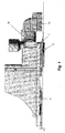
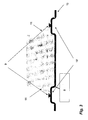
- Figures 1 and 2 illustrate two different views of one and the same accessory intended for the process according to one variant of the invention and Figure 3 illustrates a schematic view of a tank base where another accessory is fastened.
- the accessory represented in Figures 1 and 2 is a gauge support for a fuel tank that comprises a snap-riveting orifice (5) and reliefs or welding platforms (6) positioned on a stop surface (7), the purpose of which is to limit the penetration of the accessory into the molten plastic.
- the snap-riveting zone surrounding the orifice (5) is set back by 1 mm relative to the stop surface (7) so that the snap-riveting can be carried out at the same time as the welding, despite the fact that it takes place over a zone in relief (dome) of the parison.
- the cavities of the mould (not represented) have a boss, i.e. a zone in relief of complementary shape.
- the gauge support illustrated in Figures 1 and 2 is used to support a gauge intended for a secondary pouch of a saddle tank. It is hence equipped with a venturi (12) that is intended to suck up fuel in the bottom of this pouch through a filter (13) equipped with teeth and that is moulded (preferably by injection moulding) from one part with it.
- a venturi (12) that is intended to suck up fuel in the bottom of this pouch through a filter (13) equipped with teeth and that is moulded (preferably by injection moulding) from one part with it.
- the advantage of this geometry is that the height of the teeth may easily be adapted to the geometry of the bottom of the pouch for which the gauge and the venturi are intended. For this it is sufficient to equip the injection-moulding mould with a mobile and/or interchangeable part.
- the accessory (8) represented in Figure 3 is a swirl pot comprising a pump-gauge module (not represented).
- This accessory is fastened using snap rivets (9) to the bottom wall of an FT (10), these snap rivets being rivets formed from the actual wall (10) and this being to the right of domes (10') which have been moulded with the aid of a boss present in the cavities of the mould used to mould the FT from a molten plastic parison.
- the orifices through which the snap rivets (9) have been formed are located on flexible fastening tabs (11).
Description
- The present invention relates to a process for fastening an accessory to a wall of a hollow body, and in particular of a fuel tank (FT), made of plastic.
- Fuel tanks on board vehicles of various kinds must generally meet sealing and permeability standards in relation to the type of usage for which they are designed and the environmental requirements with which they must comply. Both in Europe and throughout the world we are currently experiencing a considerable tightening of the requirements concerned with limiting the emissions of pollutants into the atmosphere and into the environment in general.
- To limit these emissions, care is taken in particular to position the accessories (ventilation lines, valves, baffles, stiffeners, etc.) inside the tank and, to limit the number of openings through its wall, the Applicant has developed a method of initially moulding a parison that includes at least one slot for introducing thereinto (and fastening thereto) accessories during the actual moulding of the tank and thus avoiding drilling openings (see, in particular, Application
EP 1 110 697 ). - The Applicant has also developed a particular method for this fastening (in situ snap-riveting, the subject of Application
WO 2006/008308 , the content of which is, for this purpose, incorporated by reference into the present application) and also improvements that are respectively the subject of international ApplicationsWO 2007/093573 andPCT/EP 2008/059042 - The object of the aforementioned Application
WO 2007/093573 is to provide a process that allows an accessory to be incorporated into a plastic fuel tank during its manufacture by moulding, without generating deformations after the tank has cooled, when the accessory is fastened thereto. In this process, the accessory is provided, at at least one of its fastening points, with a fastening part such that, although the accessory is fastened to the wall of the tank, it can move relative to the corresponding fastening point on the wall of the tank. - Although this approach makes it possible to solve the deformations generated by the differential shrinkage of the accessory and of the tank during post-moulding cooling, the Applicant has however observed the formation of a hollow (depression or concave relief when seen from outside the tank, convex relief when seen from the inside) in the wall of the tank and to the right of the location where the accessory is fastened. Moreover, depending on the geometry of the accessory, the Applicant has also noticed in certain cases the appearance of beads of material trapping at least one portion of the accessory in the wall of the tank, which adversely affects the aforementioned mobility and the homogeneity of the parison (with leakage risks that result therefrom).
DE 10 2006 006469 A1 discloses a method for producing an article that encloses built-in parts and has the form of a hollow body made of thermoplastic material. The hollow body is advantageously embodied as a fuel container. The method consists in the extrusion of one or several web-type or tubular premoulds of plastified material, said premoulds being pressed against the open parts of a moulding tool forming a cavity. At least one built-in part to be enclosed by the finished article is placed between the parts of the moulding tool, the tool being closed around the premoulds and the built-in part. The premoulds take the exterior form of the article within the cavity enclosed by the tool. The built-in parts are pressed against the inner wall of the yet plastic material during on immediately after the moulding process so that the plastic of the hollow body penetrates and flows after at least one recess or opening of the built-in part.DE 100 10 900 A1 discloses a combined extrusion-moulding process that enables the production of resin-based containers with well-defined wall thicknesses from the resins usually used in blow molding, in which even complex forms are technically easy to produce. This preferably happens at the stage at which the preform is cut off during its expulsion, which preform is then pressed between the core and external mold halves, and welded in the same form. The inclusion of system parts at precise positions, and galvanization of inner surfaces, are made possible in a process-secure manner. Large parts are preferably produced using vertically oriented extrusion machines, whereby the preform is being held by a supporting device during its expulsion. - The object of the invention is hence to provide a process that makes it possible to solve these problems and to fasten an accessory to a hollow body while greatly smiting the deformations of its wall.
- This goal is achieved by raising (putting in relief) the snap-riveting zone both as regards the rest of the body wall (outside this zone/area) as regards the rest of the accessory.
- For this purpose, the invention relates to a process for fastening an accessory to a hollow body obtained by moulding a molten plastic parison, this fastening taking place by snap-riveting with the aid of a tool during the actual moulding of the parison, according to claim 1.
- Thus, for example, the Applicant has surprisingly observed that the fact of fastening an accessory with 3 snap rivets having a diameter of 1 cm each located on a dome of around 3 cm in diameter and 1 cm in height made it possible to reduce the depth of the hollow formed to the right of the accessory by a factor of 7. The choice of 3 snap rivets results from the fact that to obtain a fastening that has perfect isostatism, it is ideally necessary to provide 3 fastening points that unequivocally define a fastening plane for the part, thus avoiding an unsatisfactory fastening.
- The hollow body to which the invention applies is preferably a tank for a motor vehicle intended to contain fuel, a pollution-control additive or any other liquid on board the vehicle. It may be a fuel tank (FT) or a urea tank (urea being an additive that is used to purify the exhaust gases of NOx). It applies particularly well to FTs.
- The term "FT" is understood to mean an impermeable tank, able to store fuel under diverse and varied usage and environmental conditions. An example of this tank is that with which motor vehicles are fitted.
- The term "plastic" means any material comprising at least one synthetic resin polymer.
- Any type of plastic may be suitable. Particularly suitable plastics belong to the category of thermoplastics.
- The term "thermoplastic" is understood to mean any thermoplastic polymer, including thermoplastic elastomers, and also blends thereof. The term "polymer" is understood to mean both homopolymers and copolymers (especially binary or ternary copolymers). Examples of such copolymers are, non-limitingly : random copolymers, linear block copolymers, other block copolymers and graft copolymers.
- Any type of thermoplastic polymer or copolymer, the melting point of which is below the decomposition temperature, is suitable. Synthetic thermoplastics having a melting range spread over at least 10 degrees Celsius are particularly suitable. Examples of such materials include those that exhibit polydispersion in their molecular weight.
- In particular, it is possible to use polyolefins, thermoplastic polyesters, polyketones, polyamides and copolymers thereof. A blend of polymers or copolymers may also be used ; similarly it is also possible to use a blend of polymeric materials with inorganic, organic and/or natural fillers such as, for example but non-limitingly : carbon, salts and other inorganic derivatives, natural or polymeric fibres. It is also possible to use multilayer structures composed of stacked and joined layers comprising at least one of the polymers or copolymers described above.
- One polymer that is often used is polyethylene. Excellent results have been obtained with high-density polyethylene (HDPE).
- The wall of the tank may be composed of a single thermoplastic layer, or of two layers. One or more other possible additional layers may, advantageously, be composed of layers made of a barrier material to liquids and/or gases. Preferably, the nature and thickness of the barrier layer are chosen so as to minimize the permeability of liquids and gases in contact with the internal surface of the tank. Preferably, this layer is based on a barrier resin, that is to say a resin that is impermeable to the fuel such as, for example, EVOH (a partially hydrolysed ethylene/vinyl acetate copolymer). Alternatively, the tank may be subjected to a surface treatment (fluorination or sulphonation) for the purpose of making it impermeable to the fuel.
- When the tank according to the invention is a fuel tank, it preferably comprises an EVOH-based barrier layer located between the HDPE-based outer layers.
- According to the invention, the tank is produced by moulding a parison. The term "parison" is understood to mean a generally extruded preform of molten plastic that is intended to form the wall of the tank after moulding to the required shapes and dimensions. This preform does not necessarily have to be a one-piece preform.
- Thus, advantageously, the parison is in fact made up of two separate pieces, which may be two sheets, for example. However, these pieces preferably result from cutting one and the same extruded tubular parison as described in the aforementioned Application
EP 1 110 697 , the content of which is, for this purpose, incorporated by reference in the present application. According to this variant, once a single parison has been extruded, this parison is cut over its entire length, along two diametrically opposed lines, to obtain two separate portions (sheets). - Compared with the moulding of two separately extruded sheets, of constant thickness, this approach allows the use of parisons having a variable thickness (that is to say a thickness that is not constant over their length), which are obtained by a suitable extrusion device (generally an extruder provided with a die having a positionally-adjustable mandrel). Such a parison takes account of the thickness reduction that occurs during moulding at certain points on the parison, as a result of non-constant levels of deformation of the material in the mould.
- After a parison has been moulded in two pieces, these pieces generally form the lower and upper walls respectively of the fuel tank, each having an inner surface (pointing towards the inside of the tank) and an outer surface (pointing towards the outside of the tank).
- The mould used in the process according to this variant of the invention preferably comprises a core, i.e. a part of suitable size and shape for being able to be inserted between the cavities of the mould when the parison is located therein and to fasten thereto the components inside the tank without the edges of the parison being welded (since the core must be removed before the final moulding of the tank, a step during which the welding of the parison sections is carried out). Such a part (core) is, for example, described in Patent
GB 1 410 215 - This mould also preferably comprises two cavities that are intended to be in contact with the outer surface of the parison, the parison being moulded by blow moulding (pressing the parison against these cavities using a pressurized gas injected inside the parison) and/or by thermoforming (drawing a vacuum behind the mould cavities).
- Preferably, it takes place by blow moulding, but preferably while also providing suction (drawing a vacuum) behind the cavities to keep the parison in the mould when the latter is not closed and pressurized. Hence, it preferably comprises a degassing step prior to step (6) of the process that will be described below. Generally, in order to do this the parison is first pierced (for example by puncturing it with a needle) and then the fluid is discharged from the mould (for example using a valve).
- In the process according to the invention, the accessory is fastened to the inner surface of the paraison by snap-riveting, preferably after the parison has been pre-blow moulded, i.e. stuck to the cavities of the mould. In the variant explained above, according to which the parison is in 2 sections and is moulded using a mould comprising cavities and a core, this snap-riveting is preferably carried out using a device attached to the core that generally comprises a jack.
- Hence, one particularly preferred variant of the process according to the invention comprises the following steps :
- 1. the parison is introduced into the mould cavities ;
- 2. the core is introduced inside the parison, said core having first been fitted with the accessory and its connector ;
- 3. the mould is closed so that the cavities come into leaktight contact with the core ;
- 4. the parison is pressed against the cavities by blowing through the core and/or applying a vacuum behind the cavities ;
- 5. the accessory is fastened to the parison by snap-riveting using a device attached to the core ;
- 6. the mould is opened to withdraw the core ; and
- 7. the final moulding of the parison is carried out by blow moulding (by injecting a pressurized gas inside the parison) and/or thermoforming (by applying a vacuum behind the cavities),
- Generally, the accessory is fixed to the tank wall through at least 2 fixation points, preferably at least 3 among which, according to the invention, at least one is a snap-rivet made in situ on a dome of the tank wall through an orifice (opening) in a portion in relief of the accessory (in one piece with it or fixed to it), said relief being "hollow" i.e. concave when compared with the rest of the surface of the accessory in contact with the tank wall.
- This implies generally that the dome(s) (in the tank wall) and the "holes" in the accessory where snap-riveting occurs, are of smaller dimensions than the accessory.
- In practice, said dome(s) may be produced with the aid of a boss in the cavities of the mould, i.e. a relief of complementary shape.
- The dimensions and the shape of this dome are generally dependent on the geometry of the tank and of the accessory, in particular in the area of the snap-riveting orifice. Generally, this dome has a substantially circular cross section having a diameter of a few centimetres, for example from 2 to 5 cm, and a height ranging from 1 to 15 mm, preferably from 2 to 8 mm. The snap-riveting orifice itself preferably has a diameter greater than 1 cm, even at least equal to 2 cm.
- Within the context of the invention, the term "accessory" is understood to mean :
- any functional object or device which is generally associated with the fuel tank in its usual mode of use or operation and which cooperates with the latter in order to fulfil certain useful functions ; or
- a support for one or more such devices.
- Non-limiting examples of such devices are : liquid pumps, level gauges, delivery tubes, reservoirs or baffles internal to the fuel tank, ventilation devices (valves, pipes, etc.), electronic units and stiffening bars.
- According to one advantageous way of implementing the process according to the invention, the accessory is in fact a preassembled structure comprising a support and one or more identical or different devices that are fastened thereto via any suitable fastening means. Examples of these means are clip-fastening, screw-fastening, welding, etc. It is also advantageous for the preassembled structure to bear means allowing additional devices to be joined that would be possibly fastened subsequently. These means are also clip-fastening devices, capped holes or threaded protuberances of circular shape for screwing, surface regions that can be welded, etc. Within the same concept, the accessory may consist of a simple support that includes suitable means for subsequently fastening one or more devices. In other words, the accessory preferably includes a support that is either provided with fastening means, for one or more functional devices of the fuel tank (and which may be the cover of the accessory), or bears one or more such devices directly.
- According to the invention, the accessory comprises at least one orifice that enables the snap-riveting (common technique in the field of metallurgy that consists in moulding a rivet in situ, from molten material that has been made to overflow through an orifice in the part to be fastened and then left therein to solidify, preferably after having somewhat flattened the part that has overflowed to give it the shape of a rivet).
- According to one advantageous variant of the invention, described in the aforementioned Application
PCT/EP 2008/059042 - This relief may comprise a tongue or protuberance, the purpose of which is to ensure the clamping of the component (i.e. its fastening to the core, for example using a small piston which props up the tongue). The fact of maintaining (clamping) the component very close to its fastening tab makes it possible to ensure that this tab is completely taken charge of by the tool and therefore positioned in a good location relative to this. If the clamping is carried out too far from the fastening tab, the tab of the component cannot be attached to a good location following deformation of the material between the tab and the clamping point.
- In the case where the orifice is located at one end of a fastening tab (or of any other part of the accessory), the concave relief may be produced in a simple extension of the wall of this tab/part. In this embodiment, the "hole" in the accessory (concave recess for snap-riveting, generally complementary to the dome on the tank wall) is obtained by raising the free end of the tab versus the inferior surface of the accessory (that will be in contact with the tank wall outside the snap-riveting zone).
- In the context of the invention, although the accessory is fastened to the wall of the tank at at least one point (in this case : by snap-riveting), it is preferred that it can move relative to its fastening point on the wall of the tank.
- This mobility may be obtained in various ways. In the case where the accessory comprises at least one fastening tab, it is sufficient to ensure that this is in the form of a flexible tongue, i.e. a part that is flat (but which may be curved, folded, etc.) having a thickness, a shape and/or a constituent material that give the accessory a relative mobility with respect to the wall of the tank when it is fastened thereto. Preferably, each of the points where the accessory is fastened to the tank is provided with such a flexible tongue.
- For bulky and/or large-sized objects, according to one advantageous variant of the invention, the accessory is fastened to the parison both by snap-riveting and by welding. Most particularly preferably, the welding takes place by virtue of an attached part or connector comprising welding platforms. Advantageously, these welding platforms have the shape of a curved double lip. The welding platforms of the connector must be situated at a location and have dimensions such that during the snap-riveting they at least partially melt and enable the welding of the connector to be carried out.
- The present invention is illustrated non-limitingly by the appended
Figures 1 to 3 .Figures 1 and2 illustrate two different views of one and the same accessory intended for the process according to one variant of the invention andFigure 3 illustrates a schematic view of a tank base where another accessory is fastened. - The accessory represented in
Figures 1 and2 is a gauge support for a fuel tank that comprises a snap-riveting orifice (5) and reliefs or welding platforms (6) positioned on a stop surface (7), the purpose of which is to limit the penetration of the accessory into the molten plastic. As can be seen in this figure, the snap-riveting zone surrounding the orifice (5) is set back by 1 mm relative to the stop surface (7) so that the snap-riveting can be carried out at the same time as the welding, despite the fact that it takes place over a zone in relief (dome) of the parison. To the right of this zone, the cavities of the mould (not represented) have a boss, i.e. a zone in relief of complementary shape. - The gauge support illustrated in
Figures 1 and2 is used to support a gauge intended for a secondary pouch of a saddle tank. It is hence equipped with a venturi (12) that is intended to suck up fuel in the bottom of this pouch through a filter (13) equipped with teeth and that is moulded (preferably by injection moulding) from one part with it. The advantage of this geometry is that the height of the teeth may easily be adapted to the geometry of the bottom of the pouch for which the gauge and the venturi are intended. For this it is sufficient to equip the injection-moulding mould with a mobile and/or interchangeable part. - The accessory (8) represented in
Figure 3 is a swirl pot comprising a pump-gauge module (not represented). This accessory is fastened using snap rivets (9) to the bottom wall of an FT (10), these snap rivets being rivets formed from the actual wall (10) and this being to the right of domes (10') which have been moulded with the aid of a boss present in the cavities of the mould used to mould the FT from a molten plastic parison. - The orifices through which the snap rivets (9) have been formed are located on flexible fastening tabs (11).
Claims (9)
- Process for fastening an accessory (8) to a hollow body (10)- obtained by moulding a molten plastic parison,- this fastening taking place by snap-riveting with the aid of a tool during the actual moulding of the parison,- according to which, before carrying out the snap-riveting, the parison is locally deformed so as to surround the snap-riveting zone with a dome or relief (10') that is concave when seen from the outside of the body (10) and convex when seen from the inside, the snap-riveting zone being also in relief compared to the rest of the accessory,the process being characterized in that the dome or relief (10') has a substantially circular cross section having a diameter of 2 to 5 cm and a height of 1 to 15 mm.
- Process according to the preceding claim, characterized in that the parison is made up of two separate pieces originating from one and the same extruded tubular parison that is cut over its entire length, along two diametrically opposed lines.
- Process according to the preceding claim, characterized in that the parison is moulded using a mould comprising cavities and a core, and in that it comprises the following steps :1. the parison is introduced into the mould cavities ;2. the core is introduced inside the parison, said core having first been fitted with the accessory and its connector ;3. the mould is closed so that the cavities come into leaktight contact with the core :4. the parison is pressed against the cavities by blowing through the core and/or applying a vacuum behind the cavities ;5. the accessory (8) is fastened to the parison by snap-riveting using a device attached to the core ;6. the mould is opened to withdraw the core ; and7. the final moulding of the parison is carried out by blow moulding by injecting a pressurized gas inside the parison and/or thermo forming by applying a vacuum behind the cavities, and in that, before carrying out the snap-riveting, the parison is locally deformed so as to surround the snap-riveting zone with a dome or a relief (10') that is concave when seen from the outside of the body (10) and convex when seen from the inside, the snap-riveting zone being also in relief compared to the rest of the accessory (8).
- Process according to the preceding claim, in which the dome (10') is produced with the aid of a boss in the cavities of the mould.
- Process according to any one of the preceding claims, characterized in that the accessory (8) comprises at least one orifice (5) that enables the snap-riveting and according to which this orifice (5) is surrounded by a concave relief.
- Process according to any one of the preceding claims, characterized in that the accessory (8) can move relative to its corresponding fastening point on the body (10).
- Process according to any one of the preceding claims, characterized in that the accessory (8) is fastened to the parison both by snap-riveting and by welding.
- Process according to the preceding claim, characterized in that the welding takes place by virtue of an attached part or connector comprising welding platforms (6).
- Process according to the preceding claim, characterized in that the welding platforms (6) have the shape of a curved double lip.
Applications Claiming Priority (2)
| Application Number | Priority Date | Filing Date | Title |
|---|---|---|---|
| FR0855459A FR2934806A1 (en) | 2008-08-07 | 2008-08-07 | METHOD FOR ATTACHING AN ACCESSORY IN A HOLLOW BODY OF PLASTIC MATERIAL |
| PCT/EP2009/060198 WO2010015673A1 (en) | 2008-08-07 | 2009-08-06 | Process for fastening an accessory to a plastic hollow body |
Publications (2)
| Publication Number | Publication Date |
|---|---|
| EP2323829A1 EP2323829A1 (en) | 2011-05-25 |
| EP2323829B1 true EP2323829B1 (en) | 2012-10-10 |
Family
ID=40394367
Family Applications (1)
| Application Number | Title | Priority Date | Filing Date |
|---|---|---|---|
| EP09804576A Active EP2323829B1 (en) | 2008-08-07 | 2009-08-06 | Process for fastening an accessory to a plastic hollow body |
Country Status (5)
| Country | Link |
|---|---|
| US (1) | US9162390B2 (en) |
| EP (1) | EP2323829B1 (en) |
| CN (1) | CN102105288B (en) |
| FR (1) | FR2934806A1 (en) |
| WO (1) | WO2010015673A1 (en) |
Cited By (5)
| Publication number | Priority date | Publication date | Assignee | Title |
|---|---|---|---|---|
| US9931781B2 (en) | 2013-08-26 | 2018-04-03 | Berry Plastics Corporation | Polymeric material for container |
| US9937652B2 (en) | 2015-03-04 | 2018-04-10 | Berry Plastics Corporation | Polymeric material for container |
| US9969116B2 (en) | 2013-08-30 | 2018-05-15 | Berry Plastics Corporation | Container and process for making the same |
| US10046880B2 (en) | 2013-03-14 | 2018-08-14 | Berry Plastics Corporation | Container |
| US10266664B2 (en) | 2013-07-12 | 2019-04-23 | Berry Plastics Corporation | Polymeric material for container |
Families Citing this family (7)
| Publication number | Priority date | Publication date | Assignee | Title |
|---|---|---|---|---|
| FR2934804A1 (en) | 2008-08-07 | 2010-02-12 | Inergy Automotive Systems Res | PROCESS FOR THE MANUFACTURE OF A FUEL TANK OF PLASTIC MATERIAL. |
| FR2934806A1 (en) * | 2008-08-07 | 2010-02-12 | Inergy Automotive Systems Res | METHOD FOR ATTACHING AN ACCESSORY IN A HOLLOW BODY OF PLASTIC MATERIAL |
| FR2935289B1 (en) * | 2008-09-01 | 2013-02-22 | Inergy Automotive Systems Res | PROCESS FOR THE MANUFACTURE OF A FUEL TANK OF PLASTIC PLASTIC MATERIAL WITH PUMP. |
| FR2961738B1 (en) * | 2010-06-23 | 2014-02-28 | Inergy Automotive Systems Res | PROCESS FOR MANUFACTURING A FUEL TANK WITH A BAFFLE |
| US8973778B2 (en) * | 2012-10-29 | 2015-03-10 | Ti Automotive Technology Center Gmbh | Self-adjusting connector |
| JP5895922B2 (en) * | 2013-11-01 | 2016-03-30 | トヨタ自動車株式会社 | Fuel tank manufacturing method and fuel tank |
| JP5929875B2 (en) * | 2013-11-06 | 2016-06-08 | トヨタ自動車株式会社 | Manufacturing method of fuel tank |
Family Cites Families (43)
| Publication number | Priority date | Publication date | Assignee | Title |
|---|---|---|---|---|
| CA993165A (en) | 1971-11-22 | 1976-07-20 | Peter T. Schurman | Plastic article and blow molding method and apparatus |
| US5308427A (en) * | 1992-09-28 | 1994-05-03 | Ford Motor Company | Method for fastening plastic articles |
| US5445783A (en) * | 1993-07-06 | 1995-08-29 | Ford Motor Company | Blow molding method |
| BE1009534A3 (en) * | 1995-08-11 | 1997-05-06 | Solvay | Method for fixing an element within a hollow thermoplastic. |
| DE19849820A1 (en) * | 1998-10-29 | 2000-05-11 | Kautex Textron Gmbh & Co Kg | Fuel tank system for a motor vehicle |
| FR2801003B1 (en) * | 1999-11-12 | 2002-09-06 | Plastic Omnium Cie | PROCESS FOR PRODUCING A BLOWN ENCLOSURE PROVIDED WITH A MOUTHPIECE CAPABLE OF RECEIVING A CONDUIT, AN INSERT FOR MOLDING BY BLOWING A PARISON AND A BLOWN ENCLOSURE COMPRISING SUCH A OVERMOLDED INSERT |
| BE1013191A3 (en) * | 1999-12-22 | 2001-10-02 | Solvay | Method for producing hollow plastic material. |
| BE1013290A3 (en) * | 2000-02-18 | 2001-11-06 | Solvay | Manufacturing process for fuel tank plastic. |
| DE10010900A1 (en) * | 2000-03-07 | 2001-09-13 | Ludwig Kreth | Extrusion-pressing of high-impact, fuel tank blow-moldings, employs controlled blowing nozzle, core and separation strategy, followed by flange welding of shells formed |
| FR2806959B1 (en) * | 2000-04-03 | 2003-02-14 | Plastic Omnium Cie | METHOD FOR MANUFACTURING A BLOWER THERMOPLASTIC TANK INCORPORATING AN INSERT |
| WO2002014050A2 (en) * | 2000-08-11 | 2002-02-21 | Visteon Global Technologies, Inc. | High volume production of low permeation plastic fuel tanks using parallel offset twinsheet pressure forming |
| US6978802B2 (en) * | 2001-03-08 | 2005-12-27 | Toyoda Gosei Co., Ltd. | Fuel tank and manufacturing method thereof |
| US6810913B2 (en) * | 2002-04-26 | 2004-11-02 | Visteon Global Technologies, Inc. | Internal fuel vapor valve |
| FR2844487B1 (en) * | 2002-09-13 | 2005-05-13 | Inergy Automotive Systems Res | SAFETY SYSTEM FOR LIQUID FUEL TANK |
| FR2845356B1 (en) * | 2002-10-04 | 2005-05-13 | Inergy Automotive Systems Res | PLASTIC PLASTIC ACCESSORY PLATE FOR THERMOPLASTIC HOLLOW BODY, TANK COMPRISING AN ATTACHMENT MOUNTED ON SUCH A PLATINUM AND METHOD FOR MANUFACTURING A FUEL TANK COMPRISING SUCH A PLATINUM |
| FR2873321B1 (en) * | 2004-07-23 | 2008-05-09 | Inergy Automotive Systems Res | METHOD FOR FIXING AN ACCESSORY IN A FUEL TANK OF PLASTIC MATERIAL |
| FR2875430B1 (en) * | 2004-09-23 | 2006-12-08 | Inergy Automotive Systems Res | METHOD FOR FASTENING A PITCH ON THE WALL OF A FUEL TANK |
| FR2877256B1 (en) * | 2004-10-28 | 2008-10-03 | Inergy Automotive Systems Res | PROCESS FOR THE MANUFACTURE OF A FUEL TANK OF PLASTIC MATERIAL COMPRISING AN INTEGRATED CHUTE |
| US7455190B2 (en) * | 2004-11-15 | 2008-11-25 | Automotive Components Holdings, Llc | Fuel tank system having enhanced durability and reduced permeation |
| FR2879121B1 (en) * | 2004-12-15 | 2008-09-26 | Inergy Automotive Systems Res | METHOD FOR THE CONNECTION OF A TUBULAR PIECE OF PLASTIC MATERIAL TO A CHUTE OF A FUEL TANK ALSO IN PLASTIC MATERIAL |
| FR2879494B1 (en) * | 2004-12-16 | 2007-03-09 | Inergy Automotive Systems Res | PROCESS FOR THE PRODUCTION OF A MULTILAYER HOLLOW BODY COMPRISING AT LEAST ONE WELDING |
| FR2882962B1 (en) * | 2005-03-11 | 2009-07-10 | Inergy Automotive Systems Res | PROCESS FOR THE MANUFACTURE OF A FUEL TANK OF PLASTIC MATERIAL |
| JP5378802B2 (en) * | 2006-02-03 | 2013-12-25 | イナジー・オートモーティブ・システムズ・リサーチ・(ソシエテ・アノニム) | Method and apparatus for manufacturing a fuel tank with internal accessories |
| DE102006006469B4 (en) | 2006-02-10 | 2018-02-22 | Kautex Textron Gmbh & Co. Kg | Method for producing a plastic container |
| FR2897308B1 (en) | 2006-02-13 | 2009-01-23 | Inergy Automotive Systems Res | METHOD FOR FIXING AN ACCESSORY IN A FUEL TANK OF PLASTIC MATERIAL |
| FR2900090B1 (en) * | 2006-04-20 | 2010-09-10 | Inergy Automotive Systems Res | PROCESS FOR THE MANUFACTURE OF A FUEL TANK OF PLASTIC MATERIAL COMPRISING A CONNECTION WITH A SCREW |
| FR2900091B1 (en) * | 2006-04-21 | 2010-09-10 | Inergy Automotive Systems Res | PROCESS FOR THE MANUFACTURE OF A FUEL TANK OF PLASTIC MATERIAL |
| US9023264B2 (en) * | 2006-07-03 | 2015-05-05 | Kautex Textron Gmbh & Co. Kg | Method for producing a container of thermoplastic material |
| US8268212B2 (en) * | 2006-10-05 | 2012-09-18 | Inergy Automotive Systems Research (S.A.) | Process for manufacturing a plastic hollow body from a parison and die for extruding a parison |
| US7861885B2 (en) * | 2006-12-15 | 2011-01-04 | Kautex Textron Gmbh & Co. Kg | Fuel tank of thermoplastic material with functional installation fitments for air intake and venting, for fuel take-off or the like |
| US7829819B2 (en) * | 2007-02-08 | 2010-11-09 | Automotive Components Holdings, Llc | Attaching a component to an internal surface of a tank formed of polymer |
| FR2915923B1 (en) * | 2007-05-10 | 2009-07-10 | Inergy Automotive Systems Res | PROCESS FOR MANUFACTURING A FUEL TANK WITH INTERNAL ACCESSORY |
| FR2918595B1 (en) * | 2007-07-11 | 2009-10-09 | Inergy Automotive Systems Res | METHOD FOR FIXING AN ACCESSORY IN A PLASTIC RESERVOIR |
| DE602008006576D1 (en) * | 2007-10-02 | 2011-06-09 | METHOD FOR PRODUCING A PLASTIC FUEL TANK | |
| FR2929891B1 (en) * | 2008-04-10 | 2010-09-03 | Inergy Automotive Systems Res | METHOD FOR FASTENING A COMPONENT IN A FUEL TANK |
| DE102008027823B3 (en) * | 2008-06-11 | 2010-02-11 | Kautex Textron Gmbh & Co. Kg | Process for producing a fuel tank for motor vehicles and fuel tank for motor vehicles |
| US8496867B2 (en) * | 2008-06-23 | 2013-07-30 | Inergy Automotive Systems Research (Societe Anonyme) | Process for manufacturing a fuel tank |
| FR2934806A1 (en) * | 2008-08-07 | 2010-02-12 | Inergy Automotive Systems Res | METHOD FOR ATTACHING AN ACCESSORY IN A HOLLOW BODY OF PLASTIC MATERIAL |
| FR2934805A1 (en) | 2008-08-07 | 2010-02-12 | Inergy Automotive Systems Res | METHOD FOR ATTACHING AN ACCESSORY TO A HOLLOW BODY OF PLASTIC MATERIAL DURING MOLDING |
| FR2934804A1 (en) | 2008-08-07 | 2010-02-12 | Inergy Automotive Systems Res | PROCESS FOR THE MANUFACTURE OF A FUEL TANK OF PLASTIC MATERIAL. |
| FR2935289B1 (en) | 2008-09-01 | 2013-02-22 | Inergy Automotive Systems Res | PROCESS FOR THE MANUFACTURE OF A FUEL TANK OF PLASTIC PLASTIC MATERIAL WITH PUMP. |
| FR2937705B1 (en) * | 2008-10-24 | 2010-11-12 | Inergy Automotive Systems Res | FUEL TANK COMPRISING A VENTILATION SYSTEM EQUIPPED WITH A LIQUID / STEAM SEPARATOR |
| US8658079B2 (en) * | 2009-01-19 | 2014-02-25 | Inergy Automotive Systems Research (Societe Anonyme) | Process for manufacturing a fuel tank |
-
2008
- 2008-08-07 FR FR0855459A patent/FR2934806A1/en not_active Withdrawn
-
2009
- 2009-08-06 EP EP09804576A patent/EP2323829B1/en active Active
- 2009-08-06 US US13/057,203 patent/US9162390B2/en active Active
- 2009-08-06 WO PCT/EP2009/060198 patent/WO2010015673A1/en active Application Filing
- 2009-08-06 CN CN200980129443.8A patent/CN102105288B/en active Active
Cited By (7)
| Publication number | Priority date | Publication date | Assignee | Title |
|---|---|---|---|---|
| US10046880B2 (en) | 2013-03-14 | 2018-08-14 | Berry Plastics Corporation | Container |
| US10266664B2 (en) | 2013-07-12 | 2019-04-23 | Berry Plastics Corporation | Polymeric material for container |
| US9931781B2 (en) | 2013-08-26 | 2018-04-03 | Berry Plastics Corporation | Polymeric material for container |
| US9969116B2 (en) | 2013-08-30 | 2018-05-15 | Berry Plastics Corporation | Container and process for making the same |
| US9937652B2 (en) | 2015-03-04 | 2018-04-10 | Berry Plastics Corporation | Polymeric material for container |
| US10173359B2 (en) | 2015-03-04 | 2019-01-08 | Berry Plastics Corporation | Multi-layer tube and process of making the same |
| US10265903B2 (en) | 2015-03-04 | 2019-04-23 | Berry Plastics Corporation | Container and process for making the same |
Also Published As
| Publication number | Publication date |
|---|---|
| CN102105288A (en) | 2011-06-22 |
| FR2934806A1 (en) | 2010-02-12 |
| CN102105288B (en) | 2014-02-12 |
| US9162390B2 (en) | 2015-10-20 |
| WO2010015673A1 (en) | 2010-02-11 |
| EP2323829A1 (en) | 2011-05-25 |
| US20110131788A1 (en) | 2011-06-09 |
Similar Documents
| Publication | Publication Date | Title |
|---|---|---|
| EP2323829B1 (en) | Process for fastening an accessory to a plastic hollow body | |
| EP2323830B1 (en) | Process for fastening an accessory to a plastic hollow body during the moulding thereof and a connection piece | |
| EP2511069B1 (en) | Process for manufacturing a plastic fuel tank | |
| EP2167305B1 (en) | Method for fastening an accessory to a plastic fuel tank | |
| US8163228B2 (en) | Method for manufacturing a plastic fuel tank | |
| US8741207B2 (en) | Method for manufacturing a plastic fuel tank comprising a built-in neck | |
| EP2946907B1 (en) | Process for manufacturing a fuel tank equipped with an internal accessory | |
| US8122604B2 (en) | Method for fastening an accessory to a plastic fuel tank | |
| EP2195153B1 (en) | Process for manufacturing a plastic fuel tank | |
| US6814921B1 (en) | Method for making a fuel tank in plastic material | |
| US20110131789A1 (en) | Process for manufacturing a plastic fuel tank equipped with a pump | |
| CN107160657B (en) | Method for producing a fuel tank provided with internal accessories | |
| EP2981427B1 (en) | A component for a vehicle plastic article such as a fuel tank | |
| CN106182699B (en) | Method for producing a hollow body, in particular a fuel tank |
Legal Events
| Date | Code | Title | Description |
|---|---|---|---|
| PUAI | Public reference made under article 153(3) epc to a published international application that has entered the european phase |
Free format text: ORIGINAL CODE: 0009012 |
|
| 17P | Request for examination filed |
Effective date: 20110307 |
|
| AK | Designated contracting states |
Kind code of ref document: A1 Designated state(s): AT BE BG CH CY CZ DE DK EE ES FI FR GB GR HR HU IE IS IT LI LT LU LV MC MK MT NL NO PL PT RO SE SI SK SM TR |
|
| AX | Request for extension of the european patent |
Extension state: AL BA RS |
|
| DAX | Request for extension of the european patent (deleted) | ||
| GRAJ | Information related to disapproval of communication of intention to grant by the applicant or resumption of examination proceedings by the epo deleted |
Free format text: ORIGINAL CODE: EPIDOSDIGR1 |
|
| GRAP | Despatch of communication of intention to grant a patent |
Free format text: ORIGINAL CODE: EPIDOSNIGR1 |
|
| RTI1 | Title (correction) |
Free format text: PROCESS FOR FASTENING AN ACCESSORY TO A PLASTIC HOLLOW BODY |
|
| GRAP | Despatch of communication of intention to grant a patent |
Free format text: ORIGINAL CODE: EPIDOSNIGR1 |
|
| GRAS | Grant fee paid |
Free format text: ORIGINAL CODE: EPIDOSNIGR3 |
|
| GRAA | (expected) grant |
Free format text: ORIGINAL CODE: 0009210 |
|
| AK | Designated contracting states |
Kind code of ref document: B1 Designated state(s): AT BE BG CH CY CZ DE DK EE ES FI FR GB GR HR HU IE IS IT LI LT LU LV MC MK MT NL NO PL PT RO SE SI SK SM TR |
|
| REG | Reference to a national code |
Ref country code: GB Ref legal event code: FG4D |
|
| REG | Reference to a national code |
Ref country code: AT Ref legal event code: REF Ref document number: 578741 Country of ref document: AT Kind code of ref document: T Effective date: 20121015 Ref country code: CH Ref legal event code: EP |
|
| REG | Reference to a national code |
Ref country code: IE Ref legal event code: FG4D |
|
| REG | Reference to a national code |
Ref country code: DE Ref legal event code: R096 Ref document number: 602009010412 Country of ref document: DE Effective date: 20121206 |
|
| PG25 | Lapsed in a contracting state [announced via postgrant information from national office to epo] |
Ref country code: SI Free format text: LAPSE BECAUSE OF FAILURE TO SUBMIT A TRANSLATION OF THE DESCRIPTION OR TO PAY THE FEE WITHIN THE PRESCRIBED TIME-LIMIT Effective date: 20121010 |
|
| REG | Reference to a national code |
Ref country code: NL Ref legal event code: VDEP Effective date: 20121010 |
|
| REG | Reference to a national code |
Ref country code: AT Ref legal event code: MK05 Ref document number: 578741 Country of ref document: AT Kind code of ref document: T Effective date: 20121010 |
|
| REG | Reference to a national code |
Ref country code: LT Ref legal event code: MG4D |
|
| PG25 | Lapsed in a contracting state [announced via postgrant information from national office to epo] |
Ref country code: NL Free format text: LAPSE BECAUSE OF FAILURE TO SUBMIT A TRANSLATION OF THE DESCRIPTION OR TO PAY THE FEE WITHIN THE PRESCRIBED TIME-LIMIT Effective date: 20121010 Ref country code: NO Free format text: LAPSE BECAUSE OF FAILURE TO SUBMIT A TRANSLATION OF THE DESCRIPTION OR TO PAY THE FEE WITHIN THE PRESCRIBED TIME-LIMIT Effective date: 20130110 Ref country code: ES Free format text: LAPSE BECAUSE OF FAILURE TO SUBMIT A TRANSLATION OF THE DESCRIPTION OR TO PAY THE FEE WITHIN THE PRESCRIBED TIME-LIMIT Effective date: 20130121 Ref country code: LT Free format text: LAPSE BECAUSE OF FAILURE TO SUBMIT A TRANSLATION OF THE DESCRIPTION OR TO PAY THE FEE WITHIN THE PRESCRIBED TIME-LIMIT Effective date: 20121010 Ref country code: SE Free format text: LAPSE BECAUSE OF FAILURE TO SUBMIT A TRANSLATION OF THE DESCRIPTION OR TO PAY THE FEE WITHIN THE PRESCRIBED TIME-LIMIT Effective date: 20121010 Ref country code: IS Free format text: LAPSE BECAUSE OF FAILURE TO SUBMIT A TRANSLATION OF THE DESCRIPTION OR TO PAY THE FEE WITHIN THE PRESCRIBED TIME-LIMIT Effective date: 20130210 Ref country code: FI Free format text: LAPSE BECAUSE OF FAILURE TO SUBMIT A TRANSLATION OF THE DESCRIPTION OR TO PAY THE FEE WITHIN THE PRESCRIBED TIME-LIMIT Effective date: 20121010 Ref country code: HR Free format text: LAPSE BECAUSE OF FAILURE TO SUBMIT A TRANSLATION OF THE DESCRIPTION OR TO PAY THE FEE WITHIN THE PRESCRIBED TIME-LIMIT Effective date: 20121010 |
|
| PG25 | Lapsed in a contracting state [announced via postgrant information from national office to epo] |
Ref country code: GR Free format text: LAPSE BECAUSE OF FAILURE TO SUBMIT A TRANSLATION OF THE DESCRIPTION OR TO PAY THE FEE WITHIN THE PRESCRIBED TIME-LIMIT Effective date: 20130111 Ref country code: PT Free format text: LAPSE BECAUSE OF FAILURE TO SUBMIT A TRANSLATION OF THE DESCRIPTION OR TO PAY THE FEE WITHIN THE PRESCRIBED TIME-LIMIT Effective date: 20130211 Ref country code: LV Free format text: LAPSE BECAUSE OF FAILURE TO SUBMIT A TRANSLATION OF THE DESCRIPTION OR TO PAY THE FEE WITHIN THE PRESCRIBED TIME-LIMIT Effective date: 20121010 Ref country code: PL Free format text: LAPSE BECAUSE OF FAILURE TO SUBMIT A TRANSLATION OF THE DESCRIPTION OR TO PAY THE FEE WITHIN THE PRESCRIBED TIME-LIMIT Effective date: 20121010 Ref country code: BE Free format text: LAPSE BECAUSE OF FAILURE TO SUBMIT A TRANSLATION OF THE DESCRIPTION OR TO PAY THE FEE WITHIN THE PRESCRIBED TIME-LIMIT Effective date: 20121010 |
|
| PG25 | Lapsed in a contracting state [announced via postgrant information from national office to epo] |
Ref country code: AT Free format text: LAPSE BECAUSE OF FAILURE TO SUBMIT A TRANSLATION OF THE DESCRIPTION OR TO PAY THE FEE WITHIN THE PRESCRIBED TIME-LIMIT Effective date: 20121010 |
|
| PG25 | Lapsed in a contracting state [announced via postgrant information from national office to epo] |
Ref country code: CZ Free format text: LAPSE BECAUSE OF FAILURE TO SUBMIT A TRANSLATION OF THE DESCRIPTION OR TO PAY THE FEE WITHIN THE PRESCRIBED TIME-LIMIT Effective date: 20121010 Ref country code: SK Free format text: LAPSE BECAUSE OF FAILURE TO SUBMIT A TRANSLATION OF THE DESCRIPTION OR TO PAY THE FEE WITHIN THE PRESCRIBED TIME-LIMIT Effective date: 20121010 Ref country code: BG Free format text: LAPSE BECAUSE OF FAILURE TO SUBMIT A TRANSLATION OF THE DESCRIPTION OR TO PAY THE FEE WITHIN THE PRESCRIBED TIME-LIMIT Effective date: 20130110 Ref country code: DK Free format text: LAPSE BECAUSE OF FAILURE TO SUBMIT A TRANSLATION OF THE DESCRIPTION OR TO PAY THE FEE WITHIN THE PRESCRIBED TIME-LIMIT Effective date: 20121010 Ref country code: EE Free format text: LAPSE BECAUSE OF FAILURE TO SUBMIT A TRANSLATION OF THE DESCRIPTION OR TO PAY THE FEE WITHIN THE PRESCRIBED TIME-LIMIT Effective date: 20121010 |
|
| PLBE | No opposition filed within time limit |
Free format text: ORIGINAL CODE: 0009261 |
|
| STAA | Information on the status of an ep patent application or granted ep patent |
Free format text: STATUS: NO OPPOSITION FILED WITHIN TIME LIMIT |
|
| PG25 | Lapsed in a contracting state [announced via postgrant information from national office to epo] |
Ref country code: RO Free format text: LAPSE BECAUSE OF FAILURE TO SUBMIT A TRANSLATION OF THE DESCRIPTION OR TO PAY THE FEE WITHIN THE PRESCRIBED TIME-LIMIT Effective date: 20121010 Ref country code: IT Free format text: LAPSE BECAUSE OF FAILURE TO SUBMIT A TRANSLATION OF THE DESCRIPTION OR TO PAY THE FEE WITHIN THE PRESCRIBED TIME-LIMIT Effective date: 20121010 |
|
| 26N | No opposition filed |
Effective date: 20130711 |
|
| REG | Reference to a national code |
Ref country code: DE Ref legal event code: R097 Ref document number: 602009010412 Country of ref document: DE Effective date: 20130711 |
|
| PG25 | Lapsed in a contracting state [announced via postgrant information from national office to epo] |
Ref country code: CY Free format text: LAPSE BECAUSE OF FAILURE TO SUBMIT A TRANSLATION OF THE DESCRIPTION OR TO PAY THE FEE WITHIN THE PRESCRIBED TIME-LIMIT Effective date: 20121010 |
|
| REG | Reference to a national code |
Ref country code: CH Ref legal event code: PL |
|
| GBPC | Gb: european patent ceased through non-payment of renewal fee |
Effective date: 20130806 |
|
| PG25 | Lapsed in a contracting state [announced via postgrant information from national office to epo] |
Ref country code: CH Free format text: LAPSE BECAUSE OF NON-PAYMENT OF DUE FEES Effective date: 20130831 Ref country code: MC Free format text: LAPSE BECAUSE OF FAILURE TO SUBMIT A TRANSLATION OF THE DESCRIPTION OR TO PAY THE FEE WITHIN THE PRESCRIBED TIME-LIMIT Effective date: 20121010 Ref country code: LI Free format text: LAPSE BECAUSE OF NON-PAYMENT OF DUE FEES Effective date: 20130831 |
|
| REG | Reference to a national code |
Ref country code: IE Ref legal event code: MM4A |
|
| PG25 | Lapsed in a contracting state [announced via postgrant information from national office to epo] |
Ref country code: GB Free format text: LAPSE BECAUSE OF NON-PAYMENT OF DUE FEES Effective date: 20130806 Ref country code: IE Free format text: LAPSE BECAUSE OF NON-PAYMENT OF DUE FEES Effective date: 20130806 |
|
| PG25 | Lapsed in a contracting state [announced via postgrant information from national office to epo] |
Ref country code: SM Free format text: LAPSE BECAUSE OF FAILURE TO SUBMIT A TRANSLATION OF THE DESCRIPTION OR TO PAY THE FEE WITHIN THE PRESCRIBED TIME-LIMIT Effective date: 20121010 |
|
| PG25 | Lapsed in a contracting state [announced via postgrant information from national office to epo] |
Ref country code: MT Free format text: LAPSE BECAUSE OF FAILURE TO SUBMIT A TRANSLATION OF THE DESCRIPTION OR TO PAY THE FEE WITHIN THE PRESCRIBED TIME-LIMIT Effective date: 20121010 Ref country code: TR Free format text: LAPSE BECAUSE OF FAILURE TO SUBMIT A TRANSLATION OF THE DESCRIPTION OR TO PAY THE FEE WITHIN THE PRESCRIBED TIME-LIMIT Effective date: 20121010 |
|
| PG25 | Lapsed in a contracting state [announced via postgrant information from national office to epo] |
Ref country code: HU Free format text: LAPSE BECAUSE OF FAILURE TO SUBMIT A TRANSLATION OF THE DESCRIPTION OR TO PAY THE FEE WITHIN THE PRESCRIBED TIME-LIMIT; INVALID AB INITIO Effective date: 20090806 Ref country code: LU Free format text: LAPSE BECAUSE OF NON-PAYMENT OF DUE FEES Effective date: 20130806 Ref country code: MK Free format text: LAPSE BECAUSE OF FAILURE TO SUBMIT A TRANSLATION OF THE DESCRIPTION OR TO PAY THE FEE WITHIN THE PRESCRIBED TIME-LIMIT Effective date: 20121010 |
|
| REG | Reference to a national code |
Ref country code: FR Ref legal event code: PLFP Year of fee payment: 8 |
|
| REG | Reference to a national code |
Ref country code: FR Ref legal event code: PLFP Year of fee payment: 9 |
|
| REG | Reference to a national code |
Ref country code: FR Ref legal event code: PLFP Year of fee payment: 10 |
|
| P01 | Opt-out of the competence of the unified patent court (upc) registered |
Effective date: 20230515 |
|
| PGFP | Annual fee paid to national office [announced via postgrant information from national office to epo] |
Ref country code: FR Payment date: 20230830 Year of fee payment: 15 Ref country code: DE Payment date: 20230821 Year of fee payment: 15 |