EP2323803B1 - High-speed friction stir welding method and device - Google Patents
High-speed friction stir welding method and device Download PDFInfo
- Publication number
- EP2323803B1 EP2323803B1 EP09795158.6A EP09795158A EP2323803B1 EP 2323803 B1 EP2323803 B1 EP 2323803B1 EP 09795158 A EP09795158 A EP 09795158A EP 2323803 B1 EP2323803 B1 EP 2323803B1
- Authority
- EP
- European Patent Office
- Prior art keywords
- carbon steel
- steel
- base materials
- materials
- weld
- Prior art date
- Legal status (The legal status is an assumption and is not a legal conclusion. Google has not performed a legal analysis and makes no representation as to the accuracy of the status listed.)
- Not-in-force
Links
- 238000000034 method Methods 0.000 title claims description 40
- 238000003466 welding Methods 0.000 title claims description 30
- 238000003756 stirring Methods 0.000 title claims description 21
- 239000000463 material Substances 0.000 claims description 98
- 229910000975 Carbon steel Inorganic materials 0.000 claims description 28
- 239000010962 carbon steel Substances 0.000 claims description 27
- 229910000831 Steel Inorganic materials 0.000 claims description 18
- 239000010959 steel Substances 0.000 claims description 18
- 239000010935 stainless steel Substances 0.000 claims description 9
- 229910001220 stainless steel Inorganic materials 0.000 claims description 8
- 239000007787 solid Substances 0.000 claims description 7
- 229910052582 BN Inorganic materials 0.000 claims description 5
- PZNSFCLAULLKQX-UHFFFAOYSA-N Boron nitride Chemical compound N#B PZNSFCLAULLKQX-UHFFFAOYSA-N 0.000 claims description 5
- 229910003460 diamond Inorganic materials 0.000 claims description 5
- 239000010432 diamond Substances 0.000 claims description 5
- 230000008859 change Effects 0.000 claims description 4
- 229910000753 refractory alloy Inorganic materials 0.000 claims description 4
- DECCZIUVGMLHKQ-UHFFFAOYSA-N rhenium tungsten Chemical compound [W].[Re] DECCZIUVGMLHKQ-UHFFFAOYSA-N 0.000 claims description 4
- 230000009466 transformation Effects 0.000 claims description 4
- 229910000851 Alloy steel Inorganic materials 0.000 claims description 3
- 238000004519 manufacturing process Methods 0.000 claims 1
- 230000008569 process Effects 0.000 description 14
- 238000012360 testing method Methods 0.000 description 10
- 239000008186 active pharmaceutical agent Substances 0.000 description 8
- 238000002156 mixing Methods 0.000 description 6
- 229910052751 metal Inorganic materials 0.000 description 5
- 239000002184 metal Substances 0.000 description 5
- 230000003247 decreasing effect Effects 0.000 description 4
- 238000009863 impact test Methods 0.000 description 4
- 150000002739 metals Chemical class 0.000 description 4
- 230000003466 anti-cipated effect Effects 0.000 description 3
- 230000004927 fusion Effects 0.000 description 3
- 229910000838 Al alloy Inorganic materials 0.000 description 2
- XAGFODPZIPBFFR-UHFFFAOYSA-N aluminium Chemical compound [Al] XAGFODPZIPBFFR-UHFFFAOYSA-N 0.000 description 2
- 230000015572 biosynthetic process Effects 0.000 description 2
- 238000001816 cooling Methods 0.000 description 2
- 230000008021 deposition Effects 0.000 description 2
- 238000013461 design Methods 0.000 description 2
- 238000002474 experimental method Methods 0.000 description 2
- 238000010438 heat treatment Methods 0.000 description 2
- 238000000265 homogenisation Methods 0.000 description 2
- 229910001256 stainless steel alloy Inorganic materials 0.000 description 2
- -1 ASTM A106 Grade B Substances 0.000 description 1
- 102220573299 Coiled-coil domain-containing protein 92_S70C_mutation Human genes 0.000 description 1
- RYGMFSIKBFXOCR-UHFFFAOYSA-N Copper Chemical compound [Cu] RYGMFSIKBFXOCR-UHFFFAOYSA-N 0.000 description 1
- 229910000881 Cu alloy Inorganic materials 0.000 description 1
- RWSOTUBLDIXVET-UHFFFAOYSA-N Dihydrogen sulfide Chemical compound S RWSOTUBLDIXVET-UHFFFAOYSA-N 0.000 description 1
- CWYNVVGOOAEACU-UHFFFAOYSA-N Fe2+ Chemical compound [Fe+2] CWYNVVGOOAEACU-UHFFFAOYSA-N 0.000 description 1
- UFHFLCQGNIYNRP-UHFFFAOYSA-N Hydrogen Chemical compound [H][H] UFHFLCQGNIYNRP-UHFFFAOYSA-N 0.000 description 1
- FYYHWMGAXLPEAU-UHFFFAOYSA-N Magnesium Chemical compound [Mg] FYYHWMGAXLPEAU-UHFFFAOYSA-N 0.000 description 1
- 229910000861 Mg alloy Inorganic materials 0.000 description 1
- 229910000978 Pb alloy Inorganic materials 0.000 description 1
- HCHKCACWOHOZIP-UHFFFAOYSA-N Zinc Chemical compound [Zn] HCHKCACWOHOZIP-UHFFFAOYSA-N 0.000 description 1
- 229910001297 Zn alloy Inorganic materials 0.000 description 1
- 230000002411 adverse Effects 0.000 description 1
- 229910045601 alloy Inorganic materials 0.000 description 1
- 239000000956 alloy Substances 0.000 description 1
- 239000004411 aluminium Substances 0.000 description 1
- 229910052782 aluminium Inorganic materials 0.000 description 1
- 238000013459 approach Methods 0.000 description 1
- 229910000963 austenitic stainless steel Inorganic materials 0.000 description 1
- 239000000919 ceramic Substances 0.000 description 1
- 239000000356 contaminant Substances 0.000 description 1
- 239000010949 copper Substances 0.000 description 1
- 230000007547 defect Effects 0.000 description 1
- 238000011161 development Methods 0.000 description 1
- 230000018109 developmental process Effects 0.000 description 1
- 238000006073 displacement reaction Methods 0.000 description 1
- 229910001039 duplex stainless steel Inorganic materials 0.000 description 1
- 239000000945 filler Substances 0.000 description 1
- 230000004907 flux Effects 0.000 description 1
- 238000007656 fracture toughness test Methods 0.000 description 1
- 238000007499 fusion processing Methods 0.000 description 1
- 229910052739 hydrogen Inorganic materials 0.000 description 1
- 239000001257 hydrogen Substances 0.000 description 1
- 230000006872 improvement Effects 0.000 description 1
- 238000009434 installation Methods 0.000 description 1
- 239000011777 magnesium Substances 0.000 description 1
- 238000002844 melting Methods 0.000 description 1
- 230000008018 melting Effects 0.000 description 1
- 239000007769 metal material Substances 0.000 description 1
- 238000012986 modification Methods 0.000 description 1
- 230000004048 modification Effects 0.000 description 1
- 229910052755 nonmetal Inorganic materials 0.000 description 1
- 238000013021 overheating Methods 0.000 description 1
- 239000004033 plastic Substances 0.000 description 1
- 238000007711 solidification Methods 0.000 description 1
- 230000008023 solidification Effects 0.000 description 1
- 238000007655 standard test method Methods 0.000 description 1
- 238000012956 testing procedure Methods 0.000 description 1
- 229920001169 thermoplastic Polymers 0.000 description 1
- 230000007704 transition Effects 0.000 description 1
- WFKWXMTUELFFGS-UHFFFAOYSA-N tungsten Chemical compound [W] WFKWXMTUELFFGS-UHFFFAOYSA-N 0.000 description 1
- 229910052721 tungsten Inorganic materials 0.000 description 1
- 239000010937 tungsten Substances 0.000 description 1
- 239000011701 zinc Substances 0.000 description 1
Images

Classifications
-
- B—PERFORMING OPERATIONS; TRANSPORTING
- B23—MACHINE TOOLS; METAL-WORKING NOT OTHERWISE PROVIDED FOR
- B23K—SOLDERING OR UNSOLDERING; WELDING; CLADDING OR PLATING BY SOLDERING OR WELDING; CUTTING BY APPLYING HEAT LOCALLY, e.g. FLAME CUTTING; WORKING BY LASER BEAM
- B23K20/00—Non-electric welding by applying impact or other pressure, with or without the application of heat, e.g. cladding or plating
- B23K20/12—Non-electric welding by applying impact or other pressure, with or without the application of heat, e.g. cladding or plating the heat being generated by friction; Friction welding
- B23K20/122—Non-electric welding by applying impact or other pressure, with or without the application of heat, e.g. cladding or plating the heat being generated by friction; Friction welding using a non-consumable tool, e.g. friction stir welding
- B23K20/1225—Particular aspects of welding with a non-consumable tool
-
- B—PERFORMING OPERATIONS; TRANSPORTING
- B23—MACHINE TOOLS; METAL-WORKING NOT OTHERWISE PROVIDED FOR
- B23K—SOLDERING OR UNSOLDERING; WELDING; CLADDING OR PLATING BY SOLDERING OR WELDING; CUTTING BY APPLYING HEAT LOCALLY, e.g. FLAME CUTTING; WORKING BY LASER BEAM
- B23K20/00—Non-electric welding by applying impact or other pressure, with or without the application of heat, e.g. cladding or plating
- B23K20/12—Non-electric welding by applying impact or other pressure, with or without the application of heat, e.g. cladding or plating the heat being generated by friction; Friction welding
- B23K20/122—Non-electric welding by applying impact or other pressure, with or without the application of heat, e.g. cladding or plating the heat being generated by friction; Friction welding using a non-consumable tool, e.g. friction stir welding
- B23K20/1245—Non-electric welding by applying impact or other pressure, with or without the application of heat, e.g. cladding or plating the heat being generated by friction; Friction welding using a non-consumable tool, e.g. friction stir welding characterised by the apparatus
- B23K20/1255—Tools therefor, e.g. characterised by the shape of the probe
-
- B—PERFORMING OPERATIONS; TRANSPORTING
- B23—MACHINE TOOLS; METAL-WORKING NOT OTHERWISE PROVIDED FOR
- B23K—SOLDERING OR UNSOLDERING; WELDING; CLADDING OR PLATING BY SOLDERING OR WELDING; CUTTING BY APPLYING HEAT LOCALLY, e.g. FLAME CUTTING; WORKING BY LASER BEAM
- B23K2101/00—Articles made by soldering, welding or cutting
- B23K2101/04—Tubular or hollow articles
-
- B—PERFORMING OPERATIONS; TRANSPORTING
- B23—MACHINE TOOLS; METAL-WORKING NOT OTHERWISE PROVIDED FOR
- B23K—SOLDERING OR UNSOLDERING; WELDING; CLADDING OR PLATING BY SOLDERING OR WELDING; CUTTING BY APPLYING HEAT LOCALLY, e.g. FLAME CUTTING; WORKING BY LASER BEAM
- B23K2103/00—Materials to be soldered, welded or cut
- B23K2103/02—Iron or ferrous alloys
- B23K2103/04—Steel or steel alloys
-
- B—PERFORMING OPERATIONS; TRANSPORTING
- B23—MACHINE TOOLS; METAL-WORKING NOT OTHERWISE PROVIDED FOR
- B23K—SOLDERING OR UNSOLDERING; WELDING; CLADDING OR PLATING BY SOLDERING OR WELDING; CUTTING BY APPLYING HEAT LOCALLY, e.g. FLAME CUTTING; WORKING BY LASER BEAM
- B23K2103/00—Materials to be soldered, welded or cut
- B23K2103/02—Iron or ferrous alloys
- B23K2103/04—Steel or steel alloys
- B23K2103/05—Stainless steel
Definitions
- the field of the invention relates to a method of and a device for friction stir welding a first base material to a second base material according to the preamble of claims 1 and 5 (see, for example, US 6,053,391 for claim 1 and 'Recent developments in friction stir welding of thick section aluminium alloys' by J. G. Perrett et al, 6th World Congress Aluminium Two Thousand, Florence, Italy, 13-17 March 2007 for claim 5 ).
- Friction stir welding is an emerging method of fusing a variety of materials and provides numerous advantages over conventional welding methods.
- FSW is conceptually simple and typically does not require use of any filler metal or flux. As a result, a full strength bond can be achieved with optimal mechanical characteristics.
- friction stir welding is a solid state fusion process that occurs below the melting point of the material, problems associated with the heat affected zone, unwanted grain growth, shrinkage, and/or distortion can be reduced, if not even entirely avoided.
- FSW does in most cases not require post weld treatment. Even more advantageously, FSW provides an efficient and reliable way of joining selected dissimilar metals, and metals and thermoplastic polymers. Exemplary systems and methods of FSW are described in U.S. Pat. Nos. 5,460,317 and 5,794,835 . These and all other extrinsic materials discussed herein are incorporated by reference in their entirety.
- a rotating tool (most commonly a non consumable tool (NCT)) rotates at a constant angular velocity and is pressed into the anticipated weld joint line that is formed by the first and second base materials.
- NCT non consumable tool
- the tool transverses along the joint line at constant velocity, and the frictional heat between the NCT and the first and second materials plasticizes the materials that are then forced around the tool.
- the transverse movement of the tool allows the mixed material (stir zone) to form a solid state joint (weld).
- the first and second base materials that are to be joined are generally held in a fixed position relative to each other to allow proper fusion.
- a load cell is operationally coupled to the tool such that the travel load can be monitored and maintained constant to so help improve the weld quality.
- specific tool geometry is employed to improve friction and movement of plasticized material as shown in U.S. Pat. No. 7,275,675 .
- improved process and weld control was reported in U.S. Pat. No. 5,829,664 and WO 99/39861 where at least one of the work pieces were preheated.
- force controlled systems and methods frequently suffer from relatively slow transverse welding speed, and specific tool design typically limits the transverse force that can be applied, which results in slow welding speeds.
- difficulties may be encountered due to expansion, inadvertent overheating, etc.
- friction stir welding has generally only found acceptance and practical use with relatively soft or non-ferrous materials (e.g ., aluminum, magnesium, copper, zinc, and lead alloys) as these materials become plastic at relatively low temperatures.
- relatively soft or non-ferrous materials e.g ., aluminum, magnesium, copper, zinc, and lead alloys
- the use of friction stir welding of carbon steels or stainless steel has been limited by the lack of suitable tool materials that can withstand the high temperatures and pressures required to weld such harder materials.
- tools comprising polycrystalline cubic boron nitride (PCBN) and/or polycrystalline diamond (PCD) have allowed use of FSW with harder materials.
- the present invention is directed to improved configurations and methods for FSW of relatively hard materials, and especially of steel and stainless steel materials.
- the inventors identified and characterized certain process parameters in FSW critical to predictable and reproducible formation of stable welds in various steel materials.
- contemplated configurations and methods are characterized by an elevated transverse velocity (typically above 304.8 mm/min [12 in/ min]) and use of a spindle with near-zero (typically less than 12.7x10E-3 mm [5x10E-4 inch]) run out at zero load.
- Such methods and configurations significantly increase welding speed while producing reproducible welds with high integrity and strength.
- a method of friction stir welding a first base material to a second base material in which at least one of the first and second materials comprises a steel will therefore include a step of mounting a tool into a spindle of a friction stir welding apparatus, and another step of operating the apparatus at a spindle run out that allows welding at a critical transverse velocity to produce a weld between the first and second base materials.
- the weld has a tensile strength, yield strength, and/or Charpy impact strength that is at least that of the weaker of the first and second materials, and the critical transverse velocity is at least 0.005 m/s (12 inches per minute).
- the run out of the spindle at zero load is equal or less than 12.7x10E-3 mm (5x10⁻⁴ inch), more preferably equal or less than 10.16x10⁻³ mm (2x10E-4 inch), and most preferably equal or less than 5.08x10E-3 mm (2x10E-4 inch).
- the tool is manufactured from polycrystalline cubic boron nitride, refractory alloy tungsten-rhenium, or polycrystalline diamond, and is configured as a non-consumable tool.
- the tool has a (typically constant) angular velocity between 200-800 rpm and a transverse velocity of between 0.005-0.017 m/s (12-40 inches per minute). per minute.
- the transverse and angular velocities are selected such as to achieve a temperature in the weld that is below the phase change temperature and/or the solid state transformation point of the first and second base materials.
- At least one of the first and second materials comprise a steel material, and especially a carbon steel, a stainless steel, or a steel alloy.
- a steel material and especially a carbon steel, a stainless steel, or a steel alloy.
- especially contemplated materials include carbon steel ASTM A106 Grade B, carbon steel ASTM A333 Grade 6, API X42 carbon steel, API X52 carbon steel, API X60 carbon steel, and API X70 carbon steel.
- the first and second base materials have a cylindrical or planar shape, and that the FSW processes may be performed as linear FSW or orbital FSW.
- a device for friction stir welding a first base material to a second base material is defined in claim 5.
- the inventors have discovered specific process parameters in friction stir welding that yield predictable and desirable weld results in relatively hard metals, and especially steel and stainless steel. Most significantly, the inventors discovered that the transverse velocity of the NCT in such materials provides the most critical process parameter to obtain predictable and desirable weld quality, and that suitable transverse velocities can be obtained by ascertaining that the spindle that holds the NCT (or other tool) has a near-zero run out. When transverse velocity is properly taken into account, the inventors discovered that the weld will exhibit at least the same, and in most cases even better mechanical properties (e.g ., tensile strength, yield strength, Charpy notch impact strength) than the weaker of the base materials.
- mechanical properties e.g ., tensile strength, yield strength, Charpy notch impact strength
- transverse velocity of the NCT must be selected to a point below a velocity that causes damage to the NCT and/or weld ( e.g ., by breaking the NCT and/or leaving contaminants in the weld), but also to a point above a velocity that causes unwanted high temperatures (e.g ., temperature close to the phase change or transformation point of the materials to cause a non-solid state fusion or phase transformation that can lead to solidification defects).
- transverse velocity of the NCT should also be sufficiently fast to avoid or reduce over-homogenization of the materials (e.g ., mixing greater than 3 times) in the stir welded zone.
- FSW can be performed to join first and second base materials (most typically steel materials, including carbon steel, stainless steel, and steel alloys) by using a spindle that has a near-zero run out.
- first and second base materials most typically steel materials, including carbon steel, stainless steel, and steel alloys
- the near zero run out is a significant component for achieving critical transverse velocity without significantly raising the risk of tool breakage or deposition of tool material in the weld.
- run out refers to difference between the theoretical axis of rotation (which perpendicularly intersects the center of the weld) and the actual axis of rotation.
- a tool rotating in a spindle with a run out will move along a circular path wherein the path circumscribes the theoretical axis of rotation.
- a run out that would ordinarily be characterized as relatively minor e.g ., 1x10E-3 inch at zero load
- the FSW apparatus is operated at a spindle run out that allows welding at a critical transverse velocity ( infra ) to produce a weld between the first and second base materials.
- a critical transverse velocity infra
- Using such operating conditions preferably at a critical transverse velocity of at least 0.005 m/s [12 inches per minute]
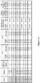
- Tables 1A and 1B of Figures 1A and 1B illustrate typical data from FSW processes in which two steel pipes of indicated materials were welded together using a non-consumable tool at negligible loss.
- each material was tested at two distinct conditions, one conventional condition using slow NCT transverse velocity, and one fast NCT transverse velocity using a spindle having a run out of less than 10.16x10E-3 mm (4x10E-4 inch). All other parameters were held constant throughout the duration of the experiment. The remaining process factors such as NCT angular velocity, downward thrust, tilt angle, and plunge were chosen based on well known practice for the respective materials.
- the test results also show that for all of the slow NCT transverse velocity trials that the weld failed the CTOD test.
- CTOD of the base material was compared to the CTOD of the weld.
- the fast NCT transverse velocity trials yielded weld CTOD that was equal to or greater than the base material CTOD
- the slow NCT transverse velocity trials yielded weld CTOD that was less than the base material CTOD.
- the transverse velocity (in/min) of the non consumable tool has a direct correlation to the integrity and stability of the weld.
- high transverse velocity with the near zero run out set up produced welds that were of equal or even better mechanical strength than the weaker of the base materials that were joined using such methods. Therefore, it should also be appreciated that the FSW according to the inventive subject matter will also provide a substantially higher rate of deposition of materials in a single pass.
- contemplated methods and configurations will also enable a method of increasing transverse velocity in friction stir welding of a first base material to a second base material (with at least one of the first and second base materials preferably comprising a steel) by either providing a spindle of a friction stir welding apparatus that has a spindle run out that allows welding at a critical transverse velocity to produce a weld between the first base material to a second base material (with at least one of the first and second base materials preferably comprising a steel) by either providing a spindle of a friction stir welding apparatus that has a spindle run out that allows welding at a critical transverse velocity to produce a weld between the first
- test results were not limited to a single steel material, but were found to apply to numerous other materials as shown in the Tables.
- Further suitable materials include other steel materials (e.g ., ASTM A106 Grade B, carbon steel ASTM A333 Grade 6, API X42 carbon steel, API X52 carbon steel, API X60 carbon steel, and API X70 carbon steel), stainless steel, duplex stainless steel, super austenitic stainless steel, low and high alloy steels, and numerous other metals.
- the FSW process according to the inventive subject matter includes processes in which same, similar, and dissimilar materials are being joined. Therefore, even non-metal materials and especially polymeric materials are deemed suitable for use herein.
- Non-consumable tools may comprise tool steels, ceramics (e.g ., polycrystalline diamond (PCD), polycrystalline cubic boron nitride (PCBN), refractory alloy tungsten-rhenium (W-Re)), and all reasonable combinations thereof.
- PCD polycrystalline diamond
- PCBN polycrystalline cubic boron nitride
- W-Re refractory alloy tungsten-rhenium
- the tool withstood substantially increased lateral loads and so supported transverse velocities of 0.0085 m/s (20 inches per minute) (and even higher). Therefore, and especially where latest generation tools are employed, transverse velocities of between 0.0042 and 0.0169 m/s (10 and 40 inches per minute) and even higher are contemplated (with angular velocities of up to 1200 rpm).
- such operating conditions avoid over-homogenization and therefore provide improved mechanical weld properties.
- the optimal transverse velocity of the tool is typically between 0.005 and 0.0169 m/s (12 to 40 inches per minute) to obtain mechanical properties of the weld that are equal to or better than the mechanical properties of the weaker of the two base materials.
- the weld mechanical properties exhibited a step function at a NCT transverse velocity, typically within the range of 0.003 and 0.005 m/s (7 to 12 inches per minute).
- Transverse velocities above the step function lead to less mixing (and with that less heating) of the material while transverse velocities below the step function lead to more mixing (and with that more heating) of the material.
- the mechanical properties of the weld changed dramatically, resulting in a switch from unacceptable weld properties to acceptable properties.
- some transverse velocities below the step function are also deemed suitable for use herein and are typically limited at the lower end by velocities that produce undesirable temperatures (e.g ., close to a phase or solid state transition point of a material).
- the angular velocity of the NCT is, according to the present invention, in the range of 200 rpm to 800 rpm, even more typically in the range of 300 rpm to 700 rpm, and most typically in the range of 400 rpm to 600 rpm (see e.g ., Tables 1A and IB). It should further be noted that in most tests the angular velocity was maintained constant while the transverse velocity was changed. However, it should be appreciated that in other weld systems ( e.g ., using different material thickness, types, etc.) these parameters may change as the weld is a function of both angular velocity and transverse speed.
- FIG. 2 shows an exemplary graph illustrating anticipated mixing as a function of transverse velocity and angular velocities (here: 400, 800, and 1200 rpm).
Landscapes
- Engineering & Computer Science (AREA)
- Mechanical Engineering (AREA)
- Pressure Welding/Diffusion-Bonding (AREA)
Description
- The field of the invention relates to a method of and a device for friction stir welding a first base material to a second base material according to the preamble of claims 1 and 5 (see, for example,
US 6,053,391 for claim 1 and 'Recent developments in friction stir welding of thick section aluminium alloys' by J. G. Perrett et al, 6th World Congress Aluminium Two Thousand, Florence, Italy, 13-17 March 2007 for claim 5). - Friction stir welding (FSW) is an emerging method of fusing a variety of materials and provides numerous advantages over conventional welding methods. FSW is conceptually simple and typically does not require use of any filler metal or flux. As a result, a full strength bond can be achieved with optimal mechanical characteristics. Moreover, as friction stir welding is a solid state fusion process that occurs below the melting point of the material, problems associated with the heat affected zone, unwanted grain growth, shrinkage, and/or distortion can be reduced, if not even entirely avoided. Still further, FSW does in most cases not require post weld treatment. Even more advantageously, FSW provides an efficient and reliable way of joining selected dissimilar metals, and metals and thermoplastic polymers. Exemplary systems and methods of FSW are described in
U.S. Pat. Nos. 5,460,317 and5,794,835 . These and all other extrinsic materials discussed herein are incorporated by reference in their entirety. - In practice, a rotating tool (most commonly a non consumable tool (NCT)) rotates at a constant angular velocity and is pressed into the anticipated weld joint line that is formed by the first and second base materials. In most cases, the tool transverses along the joint line at constant velocity, and the frictional heat between the NCT and the first and second materials plasticizes the materials that are then forced around the tool. The transverse movement of the tool allows the mixed material (stir zone) to form a solid state joint (weld). During operation, the first and second base materials that are to be joined are generally held in a fixed position relative to each other to allow proper fusion.
- While FSW provides numerous advantages over many conventional welding methods, the stability and integrity of the weld formed by friction stir welding is a function of several process parameters, which may significantly alter the mechanical properties of the solid state fusion. As relatively little is known about the specific contribution of one or more parameters in forming a stable weld between two materials, reliable and reproducible weld formation is often a matter of trial and error and the multitude of possible determinants will often preclude a rationale process design. Consequently, numerous diverse approaches have been undertaken to improve weld integrity. For example, systems and methods for control over the downforce of the tool into the material have been described as one important parameter as reported in
U.S. Pat. No. 6,050,475 . Similarly, as disclosed inU.S. Pat. No. 7,216,793 , a load cell is operationally coupled to the tool such that the travel load can be monitored and maintained constant to so help improve the weld quality. In yet other known methods, specific tool geometry is employed to improve friction and movement of plasticized material as shown inU.S. Pat. No. 7,275,675 . Alternatively, improved process and weld control was reported inU.S. Pat. No. 5,829,664 andWO 99/39861 - Moreover, friction stir welding has generally only found acceptance and practical use with relatively soft or non-ferrous materials (e.g., aluminum, magnesium, copper, zinc, and lead alloys) as these materials become plastic at relatively low temperatures. However, the use of friction stir welding of carbon steels or stainless steel has been limited by the lack of suitable tool materials that can withstand the high temperatures and pressures required to weld such harder materials. Only more recently, tools comprising polycrystalline cubic boron nitride (PCBN) and/or polycrystalline diamond (PCD) have allowed use of FSW with harder materials.
- For example, certain carbon steel materials (here: S70C carbon steel) have been welded using FSW by decreasing the peak temperature and by decreasing the cooling rate to less than the lower critical cooling rate as described in Scripta Materialia Volume 56, Issue 7, April 2007, Pages 637-640. Unfortunately, the transverse speed was undesirably low (at 1-4 in/min). Similarly, successful FSW of certain stainless steel materials using a tungsten tool was reported (Materialwissenschaft und Werkstofftechnik, Volume 38 )), but again, transverse speed was limited to 38.1 to 101.6 mm/min (1 1/2 to 4 in/ min) at 1 000 rpm. Still
- Therefore, even though FSW holds significant promise in joining various materials, numerous questions and concerns still remain. Consequently, there is a need to identify critical FSW process parameters to obtain and optimize welds with predictable and desirable integrity and stability, especially where steel materials are to be welded.
- The present invention is directed to improved configurations and methods for FSW of relatively hard materials, and especially of steel and stainless steel materials. In especially preferred aspects of the inventive subject matter, the inventors identified and characterized certain process parameters in FSW critical to predictable and reproducible formation of stable welds in various steel materials. Most significantly, contemplated configurations and methods are characterized by an elevated transverse velocity (typically above 304.8 mm/min [12 in/ min]) and use of a spindle with near-zero (typically less than 12.7x10E-3 mm [5x10E-4 inch]) run out at zero load. Such methods and configurations significantly increase welding speed while producing reproducible welds with high integrity and strength.
- In one aspect of the inventive subject matter, a method of friction stir welding a first base material to a second base material is defined in claim 1, in which at least one of the first and second materials comprises a steel will therefore include a step of mounting a tool into a spindle of a friction stir welding apparatus, and another step of operating the apparatus at a spindle run out that allows welding at a critical transverse velocity to produce a weld between the first and second base materials. Most typically, the weld has a tensile strength, yield strength, and/or Charpy impact strength that is at least that of the weaker of the first and second materials, and the critical transverse velocity is at least 0.005 m/s (12 inches per minute).
- In particularly preferred aspects, the run out of the spindle at zero load is equal or less than 12.7x10E-3 mm (5x10⁻⁴ inch), more preferably equal or less than 10.16x10⁻³ mm (2x10E-4 inch), and most preferably equal or less than 5.08x10E-3 mm (2x10E-4 inch). Additionally, it is preferred that at least part of the tool is manufactured from polycrystalline cubic boron nitride, refractory alloy tungsten-rhenium, or polycrystalline diamond, and is configured as a non-consumable tool. While not limiting to the inventive subject matter, it is generally preferred that the tool has a (typically constant) angular velocity between 200-800 rpm and a transverse velocity of between 0.005-0.017 m/s (12-40 inches per minute). per minute. According to the present invention, the transverse and angular velocities are selected such as to achieve a temperature in the weld that is below the phase change temperature and/or the solid state transformation point of the first and second base materials.
- It is further generally preferred that at least one of the first and second materials comprise a steel material, and especially a carbon steel, a stainless steel, or a steel alloy. For example, especially contemplated materials include carbon steel ASTM A106 Grade B, carbon steel ASTM A333
Grade 6, API X42 carbon steel, API X52 carbon steel, API X60 carbon steel, and API X70 carbon steel. It should still further be appreciated that the first and second base materials have a cylindrical or planar shape, and that the FSW processes may be performed as linear FSW or orbital FSW. - According to the present invention, a device for friction stir welding a first base material to a second base material is defined in claim 5.
- Various objects, features, aspects and advantages of the present invention will become more apparent from the following detailed description of preferred embodiments of the invention.
-
-
Figures 1A and1B are tables illustrating selected FSW conditions and test results for welds produced with conventional FSW parameters and FSW weld parameters according to the inventive subject matter. -
Figure 2 is a graph illustrating anticipated mixing as a function of transverse velocity and angular velocities. - The inventors have discovered specific process parameters in friction stir welding that yield predictable and desirable weld results in relatively hard metals, and especially steel and stainless steel. Most significantly, the inventors discovered that the transverse velocity of the NCT in such materials provides the most critical process parameter to obtain predictable and desirable weld quality, and that suitable transverse velocities can be obtained by ascertaining that the spindle that holds the NCT (or other tool) has a near-zero run out. When transverse velocity is properly taken into account, the inventors discovered that the weld will exhibit at least the same, and in most cases even better mechanical properties (e.g., tensile strength, yield strength, Charpy notch impact strength) than the weaker of the base materials.
- Viewed from a different perspective, it was observed that the transverse velocity of the NCT must be selected to a point below a velocity that causes damage to the NCT and/or weld (e.g., by breaking the NCT and/or leaving contaminants in the weld), but also to a point above a velocity that causes unwanted high temperatures (e.g., temperature close to the phase change or transformation point of the materials to cause a non-solid state fusion or phase transformation that can lead to solidification defects). Thus, transverse velocity of the NCT should also be sufficiently fast to avoid or reduce over-homogenization of the materials (e.g., mixing greater than 3 times) in the stir welded zone.
- Therefore, it is generally contemplated that FSW can be performed to join first and second base materials (most typically steel materials, including carbon steel, stainless steel, and steel alloys) by using a spindle that has a near-zero run out. It should be noted that the near zero run out is a significant component for achieving critical transverse velocity without significantly raising the risk of tool breakage or deposition of tool material in the weld. As used herein, the term "run out" refers to difference between the theoretical axis of rotation (which perpendicularly intersects the center of the weld) and the actual axis of rotation. Thus, and viewed from a different perspective, a tool rotating in a spindle with a run out will move along a circular path wherein the path circumscribes the theoretical axis of rotation. Notably, a run out that would ordinarily be characterized as relatively minor (e.g., 1x10E-3 inch at zero load) has not only a substantial negative impact on the weld quality but also adversely affects the capability to advance the tool at desirable transverse velocity.
- Once the tool is mounted into the spindle, the FSW apparatus is operated at a spindle run out that allows welding at a critical transverse velocity (infra) to produce a weld between the first and second base materials. Using such operating conditions (preferably at a critical transverse velocity of at least 0.005 m/s [12 inches per minute]) will typically and reproducibly result in a weld that has a tensile strength, yield strength, and/or Charpy impact strength that is equal or greater than that of the weaker of the first and second base materials.
- For example, under typical FSW conditions for various steel materials as exemplarily illustrated below, conventional FSW is performed within a first working window in which the angular velocity is about 400 rpm and the transverse velocity about 0.0025 m/s (6 inches per minute). As is readily apparent, such conventional conditions typically lead to less than satisfactory welds as can be taken from the tables. In contrast and in accordance to the present invention, where the spindle and/or tool had a run out of less than 12.7x10E-3 mm (5x10E-4), and more typically less than 10.16x10E-3 mm (4x10E-4 inch), the relatively high transverse NCT velocities according to the inventive subject matter resulted in improved tensile and yield strength, ductility, and fracture toughness. More specifically, Tables 1A and 1B of
Figures 1A and1B illustrate typical data from FSW processes in which two steel pipes of indicated materials were welded together using a non-consumable tool at negligible loss. Here, each material was tested at two distinct conditions, one conventional condition using slow NCT transverse velocity, and one fast NCT transverse velocity using a spindle having a run out of less than 10.16x10E-3 mm (4x10E-4 inch). All other parameters were held constant throughout the duration of the experiment. The remaining process factors such as NCT angular velocity, downward thrust, tilt angle, and plunge were chosen based on well known practice for the respective materials. Based on typical results as seen in Tables 1A and 1B, the weld tensile and weld yield strength increased anywhere from 5.4% to 7.1% and 3.2% to 6.8%, respectively. Conversely, where the NCT travels at a slow velocity (e.g., between 3 and 8 inches per minute), the mechanical properties of the weld are inferior to those of the base material (e.g., tensile strength decreased anywhere from -6.6% to -15.0%, and yield decreased anywhere from -6.4% to -13.6% as can be taken from Tables 1A and 1B). Of course, it should be appreciated that the results will vary depending on the particular material and parameters employed. - Testing was performed to measure the yield and tensile strength, ductility, and fracture toughness. It is important to analyze the mechanical properties of the weld to verify the integrity and stability of the fused joint. The mechanical properties of the weld are of critical importance and thus demand control of input parameters, and particularly transverse velocity of the NCT. Where the fracture toughness of the weld was tested, the pass-fail criterion was established based on experimental specification ASTM E 1290-07, "Standard Test Method for Crack-Tip Opening Displacement (CTOD) Fracture Toughness Measurement", and a modified testing procedure. Table 1B contains typical test results and shows that welds according to the inventive subject matter passed the CTOD test for all of the fast NCT transverse velocity trials. On the other hand, the test results also show that for all of the slow NCT transverse velocity trials that the weld failed the CTOD test. Moreover, the CTOD of the base material was compared to the CTOD of the weld. Similarly, the fast NCT transverse velocity trials yielded weld CTOD that was equal to or greater than the base material CTOD, and the slow NCT transverse velocity trials yielded weld CTOD that was less than the base material CTOD. Such improvement over prior FSW methods is particularly significant as improved fracture toughness is critical to reliable operation of pipelines and devices under severe operating conditions. Using the FSW methods contemplated herein, embrittlement of welds under critical service (e.g., high pressure, sour gas, hydrogen environment) is substantially reduced or even entirely avoided.
- Charpy impact tests established that fast NCT transverse velocity contemplated herein was indeed superior to the conventional NCT transverse speed. The weld Charpy impact tests were equal or greater than the base material tests for all fast NCT transverse speeds. The weld Charpy impact tests were less than the base material tests for all slow NCT transverse speeds. Moreover, the weld was accepted in this criterion if the Charpy impact test were equal or greater than the base material.
- As can be readily taken from the exemplary results (and other data; not shown here), the transverse velocity (in/min) of the non consumable tool has a direct correlation to the integrity and stability of the weld. In most cases, high transverse velocity with the near zero run out set up produced welds that were of equal or even better mechanical strength than the weaker of the base materials that were joined using such methods. Therefore, it should also be appreciated that the FSW according to the inventive subject matter will also provide a substantially higher rate of deposition of materials in a single pass. Consequently, it should be appreciated that contemplated methods and configurations will also enable a method of increasing transverse velocity in friction stir welding of a first base material to a second base material (with at least one of the first and second base materials preferably comprising a steel) by either providing a spindle of a friction stir welding apparatus that has a spindle run out that allows welding at a critical transverse velocity to produce a weld between the first
- It should be noted that the test results were not limited to a single steel material, but were found to apply to numerous other materials as shown in the Tables. Further suitable materials include other steel materials (e.g., ASTM A106 Grade B, carbon steel
ASTM A333 Grade 6, API X42 carbon steel, API X52 carbon steel, API X60 carbon steel, and API X70 carbon steel), stainless steel, duplex stainless steel, super austenitic stainless steel, low and high alloy steels, and numerous other metals. Still further, it should be recognized that the FSW process according to the inventive subject matter includes processes in which same, similar, and dissimilar materials are being joined. Therefore, even non-metal materials and especially polymeric materials are deemed suitable for use herein. Also, in still further contemplated aspects of the inventive subject matter, it should be appreciated that while the data presented herein were obtained in an orbital FSW process, contemplated results and methods are not limited to such orbital welding but also apply to all other types of FSW, and especially to planar/linear non-orbital methods. - Recent advances of high strength and impact resistance tool materials have allowed a significant increase of loading on each tool. Consequently, particularly suitable tools are non-consumable tools that may comprise tool steels, ceramics (e.g., polycrystalline diamond (PCD), polycrystalline cubic boron nitride (PCBN), refractory alloy tungsten-rhenium (W-Re)), and all reasonable combinations thereof. It should further be especially noted that the NCT must be installed correctly in the friction stir welding machine for the process to have any success, and that faulty installation can cause catastrophic failures. Indeed, the inventors have discovered that (besides improved NCT materials) the amount of run out is critical to desirable performance in FSW at high transverse velocity. Remarkably, run out in heretofore known FSW devices will typically lead to catastrophic failure (e.g., breaking of the tool) and/or undesirable welds (e.g., welds with tool deposits) where the transverse velocity was increased, and especially where the transverse velocity was increased to a speed of over 0.0034 - 0042 m/s (8 - 10 inches per minute). In contrast, in devices according to the inventive subject matter where the run out was near zero (e.g., run out at zero load of less than 12.7x10E-3 mm [5x10E-4 inch], more preferably 10.16x10E-3 [5x10E-4 inch], and most preferably 5.08x10E-3 mm [2x10e-4 inch]), the tool withstood substantially increased lateral loads and so supported transverse velocities of 0.0085 m/s (20 inches per minute) (and even higher). Therefore, and especially where latest generation tools are employed, transverse velocities of between 0.0042 and 0.0169 m/s (10 and 40 inches per minute) and even higher are contemplated (with angular velocities of up to 1200 rpm). Among other advantages, such operating conditions avoid over-homogenization and therefore provide improved mechanical weld properties.
- With respect to the critical transverse velocity it is, according to the present invention, contemplated that the optimal transverse velocity of the tool is typically between 0.005 and 0.0169 m/s (12 to 40 inches per minute) to obtain mechanical properties of the weld that are equal to or better than the mechanical properties of the weaker of the two base materials. Interestingly, and as reflected in the data of the Tables and other experiments (not shown here), the weld mechanical properties exhibited a step function at a NCT transverse velocity, typically within the range of 0.003 and 0.005 m/s (7 to 12 inches per minute). Transverse velocities above the step function (critical transverse velocity) lead to less mixing (and with that less heating) of the material while transverse velocities below the step function lead to more mixing (and with that more heating) of the material. At this step function, the mechanical properties of the weld changed dramatically, resulting in a switch from unacceptable weld properties to acceptable properties. Of course, it should be recognized that the particular step may depend on the types (and similarity) of the materials. Consequently, some transverse velocities below the step function are also deemed suitable for use herein and are typically limited at the lower end by velocities that produce undesirable temperatures (e.g., close to a phase or solid state transition point of a material).
- With respect to the angular velocity of the NCT, the angular velocity is, according to the present invention, in the range of 200 rpm to 800 rpm, even more typically in the range of 300 rpm to 700 rpm, and most typically in the range of 400 rpm to 600 rpm (see e.g., Tables 1A and IB). It should further be noted that in most tests the angular velocity was maintained constant while the transverse velocity was changed. However, it should be appreciated that in other weld systems (e.g., using different material thickness, types, etc.) these parameters may change as the weld is a function of both angular velocity and transverse speed. In fact, in at least some instances it may be necessary to increase the angular velocity to achieve a fast transverse velocity. Thus, it should be appreciated that contemplated FSW methods and configurations can be applied to other angular velocities, wherein faster angular velocities will allow greater transverse speeds up to a certain point (at some point, the transverse velocity will become so great that little to no mixing occurs).
Figure 2 shows an exemplary graph illustrating anticipated mixing as a function of transverse velocity and angular velocities (here: 400, 800, and 1200 rpm). - Thus, specific embodiments and applications of friction stir welding have been disclosed. It should be apparent, however, to those skilled in the art that many more modifications besides those already described are possible without departing from the inventive concepts herein. The inventive subject matter, therefore, is not to be restricted except in the scope of the appended claims. Moreover, in interpreting both the specification and the claims, all terms should be interpreted in the broadest possible manner consistent with the context. In particular, the terms "comprises" and "comprising" should be interpreted as referring to elements, components, or steps in a non-exclusive manner, indicating that the referenced elements, components, or steps may be present, or utilized, or combined with other elements, components, or steps that are not expressly referenced. Furthermore, where a definition or use of a term in a reference herein is inconsistent or contrary to the definition of that term provided herein, the definition of that term provided herein applies and the definition of that term in the reference does not apply.
Claims (8)
- A method of friction stir welding a first base material to a second base material where at least one of the first and second base materials comprises a steel, comprising:mounting a non-consumable tool into a spindle of a friction stir welding apparatus;characterised by the following steps :operating the apparatus at a spindle run out that allows welding at a critical transverse velocity to produce a weld between the first and second base materials, wherein the run out of the spindle at zero load is equal or less than 12.7xlOE-3 mm [5xlOE-4 inch];wherein the weld has at least one of a tensile strength, a yield strength, and a Charpy impact strength that is equal or greater than that of the weaker of the first and second base materials; andwherein the critical transverse velocity is at least 0.005 m/s [12 inches per minute];wherein the tool comprises polycrystalline cubic boron nitride, refractory alloy tungsten-rhenium, or polycrystalline diamond, and is configured as a non-consumable tool;wherein the tool has an angular velocity between 200-800 rpm;wherein the transverse velocity is between 0.005-0.0169 m/s [12-40 inches per minute];wherein the transverse and angular velocities are selected such that a temperature in the weld is below a phase change temperature or a solid state transformation point of the first and second base materials.
- The method of claim 1 wherein the first and second materials are selected from the group consisting of a steel, a stainless steel, and a steel alloy.
- The method of claim 1 wherein the first and second materials are selected from the group consisting of carbon steel ASTM A106 Grade B, carbon steel ASTM A333 Grade 6, API X42 carbon steel, API X52 carbon steel, API X60 carbon steel, and API X70 carbon steel.
- The method of claim 1 wherein the first and second base materials have a cylindrical or planar shape.
- A friction stir welding device for welding a first-base material to a second base material where at least one of the first and second base materials comprises a steel, wherein the device comprises:a spindle for mounting non-consumable tool into the spindle;wherein the run out of the spindle at zero load is equal or less than 12.7x10E-3 mm [5x10E-4 inch] so to allow production of a weld between the first and second base materials at a critical transverse velocity of at least 0.005 m/s [12 inches per minute];characterised in that the tool comprises polycrystalline cubic boron nitride, refractory alloy tungsten-rhenium, or polycrystalline diamond, and is configured as a non-consumable tool;wherein the tool has, in use, an angular velocity between 200-800 rpm;wherein the transverse velocity is, in use, between 0.005-0.0169 m/s [12-40 inches per minute], so that the so produced weld has at least one of a tensile strength, a yield strength, and a Charpy impact strength that is equal or greater than that of the weaker of the first and second base materials.
- The device of claim 5 in combination with the first and second base materials, wherein wherein the first and second base materials are selected from the group consisting of a steel, a stainless steel, and a steel alloy.
- The device of claim 5 in combination with the first and second base materials, wherein wherein the first and second materials are selected from the group consisting of carbon steel ASTM A106 Grade B, carbon steel ASTM A333 Grade 6, API X42 carbon steel, API X52 carbon steel, API X60 carbon steel, and API X70 carbon steel.
- The device of claim 5 in combination with the first and second base materials, wherein wherein the first and second base materials have a cylindrical or planar shape.
Applications Claiming Priority (2)
| Application Number | Priority Date | Filing Date | Title |
|---|---|---|---|
| US7938808P | 2008-07-09 | 2008-07-09 | |
| PCT/US2009/050019 WO2010006106A1 (en) | 2008-07-09 | 2009-07-09 | High-speed friction stir welding |
Publications (3)
| Publication Number | Publication Date |
|---|---|
| EP2323803A1 EP2323803A1 (en) | 2011-05-25 |
| EP2323803A4 EP2323803A4 (en) | 2017-03-08 |
| EP2323803B1 true EP2323803B1 (en) | 2019-06-19 |
Family
ID=41507428
Family Applications (1)
| Application Number | Title | Priority Date | Filing Date |
|---|---|---|---|
| EP09795158.6A Not-in-force EP2323803B1 (en) | 2008-07-09 | 2009-07-09 | High-speed friction stir welding method and device |
Country Status (8)
| Country | Link |
|---|---|
| US (1) | US8967451B2 (en) |
| EP (1) | EP2323803B1 (en) |
| JP (1) | JP2011527638A (en) |
| CN (1) | CN102089112B (en) |
| AU (1) | AU2009268538B2 (en) |
| CA (1) | CA2730235C (en) |
| EA (1) | EA018568B1 (en) |
| WO (1) | WO2010006106A1 (en) |
Families Citing this family (8)
| Publication number | Priority date | Publication date | Assignee | Title |
|---|---|---|---|---|
| US20100136369A1 (en) * | 2008-11-18 | 2010-06-03 | Raghavan Ayer | High strength and toughness steel structures by friction stir welding |
| US20110079446A1 (en) * | 2009-10-05 | 2011-04-07 | Baker Hughes Incorporated | Earth-boring tools and components thereof and methods of attaching components of an earth-boring tool |
| US10570113B2 (en) * | 2010-04-09 | 2020-02-25 | Semiconductor Energy Laboratory Co., Ltd. | Aromatic amine derivative, light-emitting element, light-emitting device, electronic device, and lighting device |
| JP2012040584A (en) * | 2010-08-17 | 2012-03-01 | Osaka Univ | Method for bonding ferrous material |
| RU2637546C1 (en) * | 2013-11-07 | 2017-12-05 | ДжФЕ СТИЛ КОРПОРЕЙШН | Method of friction stir welding for high-strength thin-sheet or thick-sheet steel |
| JP6066216B2 (en) * | 2014-09-01 | 2017-01-25 | 株式会社日本製鋼所 | Structure excellent in low temperature toughness and method for producing the same |
| EP3450082B1 (en) * | 2017-08-31 | 2020-12-16 | Mazak Corporation | Devices and methods for increased wear resistance during low temperature friction stir processing |
| RU2720018C2 (en) * | 2018-06-07 | 2020-04-23 | Федеральное государственное бюджетное образовательное учреждение высшего образования "Астраханский государственный университет" | Method of preparation of surfaces of ends of dissimilar compounds for friction welding with mixing |
Family Cites Families (28)
| Publication number | Priority date | Publication date | Assignee | Title |
|---|---|---|---|---|
| US4318966A (en) * | 1980-03-31 | 1982-03-09 | Imperial Chemical Industries Limited | Welded structures |
| GB9125978D0 (en) | 1991-12-06 | 1992-02-05 | Welding Inst | Hot shear butt welding |
| NO942790D0 (en) | 1994-03-28 | 1994-07-27 | Norsk Hydro As | Method of friction welding and device for the same |
| US5794835A (en) | 1996-05-31 | 1998-08-18 | The Boeing Company | Friction stir welding |
| US5829664A (en) | 1996-11-15 | 1998-11-03 | Aluminum Company Of America | Resistance heated stir welding |
| US6325273B1 (en) * | 1996-12-06 | 2001-12-04 | The Lead Sheet Association | Friction welding apparatus and method |
| NO980542D0 (en) | 1998-02-09 | 1998-02-09 | Norsk Hydro As | Modified stir friction welding |
| US6053391A (en) * | 1998-05-14 | 2000-04-25 | Tower Automotive, Inc. | Friction stir welding tool |
| US6050475A (en) | 1998-05-29 | 2000-04-18 | Mcdonnell Douglas Corporation | Method and apparatus for controlling downforce during friction stir welding |
| US6986452B2 (en) | 1999-09-03 | 2006-01-17 | Lockheed Martin Corporation | Friction stir welding as a rivet replacement technology |
| JP2004337890A (en) * | 2003-05-14 | 2004-12-02 | Toyota Motor Corp | Friction stir welding equipment |
| US7216793B2 (en) | 2003-08-22 | 2007-05-15 | Edison Welding Institute, Inc. | Friction stir welding travel axis load control method and apparatus |
| US20050045695A1 (en) * | 2003-08-29 | 2005-03-03 | Subramanian Pazhayannur Ramanathan | Apparatus and method for friction stir welding using a consumable pin tool |
| JP4743609B2 (en) * | 2003-12-18 | 2011-08-10 | 日本軽金属株式会社 | Aluminum-based target and manufacturing method thereof |
| US20060032891A1 (en) * | 2004-03-24 | 2006-02-16 | Flak Richard A | Solid state processing of materials through friction stir processing and friction stir mixing |
| US20070102289A1 (en) * | 2004-07-09 | 2007-05-10 | Kazuteru Kato | Sputtering target material |
| US7275675B1 (en) | 2004-08-20 | 2007-10-02 | United States Of America As Represented By The Administrator Of The National Aeronautics And Space Administration | Friction stir weld tools |
| US7641096B2 (en) * | 2005-01-24 | 2010-01-05 | The Boeing Company | Friction stir welding apparatus |
| JP4218895B2 (en) * | 2005-02-24 | 2009-02-04 | Obara株式会社 | Friction stir spot welding equipment |
| WO2006116722A2 (en) * | 2005-04-28 | 2006-11-02 | The Pennsylvania State Research Foundation | Apparatus and method for conducting laser stir welding |
| US8141768B2 (en) * | 2006-01-27 | 2012-03-27 | Exxonmobil Research And Engineering Company | Application of high integrity welding and repair of metal components in oil and gas exploration, production and refining |
| ATE538895T1 (en) * | 2006-06-13 | 2012-01-15 | Sii Megadiamond Inc | CONNECTING THREE ELEMENTS BY A FRICTION WELDING PROCESS |
| US7694413B2 (en) * | 2006-06-30 | 2010-04-13 | Intel Corporation | Method of making a bottomless via |
| WO2008023500A1 (en) * | 2006-08-21 | 2008-02-28 | Osaka University | Process for working metal members and structures |
| US9040865B2 (en) * | 2007-02-27 | 2015-05-26 | Exxonmobil Upstream Research Company | Corrosion resistant alloy weldments in carbon steel structures and pipelines to accommodate high axial plastic strains |
| US20090200359A1 (en) * | 2008-02-13 | 2009-08-13 | Gm Global Technology Operations, Inc. | Reducing sheet distortion in friction stir processing |
| CA2733178C (en) * | 2008-08-11 | 2016-05-24 | Megastir Technologies Llc | A method for using modifiable tool control parameters to control the temperature of the tool during friction stir welding |
| CA2733025C (en) * | 2008-08-11 | 2015-12-29 | Megastir Technologies Llc | Rotary holding device for gripping tool material at elevated temperatures through multiple collar assembly |
-
2009
- 2009-07-09 EP EP09795158.6A patent/EP2323803B1/en not_active Not-in-force
- 2009-07-09 EA EA201170166A patent/EA018568B1/en not_active IP Right Cessation
- 2009-07-09 US US13/000,469 patent/US8967451B2/en not_active Expired - Fee Related
- 2009-07-09 JP JP2011517592A patent/JP2011527638A/en active Pending
- 2009-07-09 WO PCT/US2009/050019 patent/WO2010006106A1/en not_active Ceased
- 2009-07-09 CA CA2730235A patent/CA2730235C/en not_active Expired - Fee Related
- 2009-07-09 AU AU2009268538A patent/AU2009268538B2/en not_active Ceased
- 2009-07-09 CN CN200980126422.0A patent/CN102089112B/en not_active Expired - Fee Related
Non-Patent Citations (1)
| Title |
|---|
| None * |
Also Published As
| Publication number | Publication date |
|---|---|
| AU2009268538A1 (en) | 2010-01-14 |
| EA201170166A1 (en) | 2011-06-30 |
| EP2323803A4 (en) | 2017-03-08 |
| WO2010006106A1 (en) | 2010-01-14 |
| AU2009268538B2 (en) | 2011-08-25 |
| US20110174866A1 (en) | 2011-07-21 |
| US8967451B2 (en) | 2015-03-03 |
| JP2011527638A (en) | 2011-11-04 |
| CA2730235A1 (en) | 2010-01-14 |
| CN102089112A (en) | 2011-06-08 |
| EP2323803A1 (en) | 2011-05-25 |
| EA018568B1 (en) | 2013-08-30 |
| CA2730235C (en) | 2013-10-29 |
| CN102089112B (en) | 2014-11-12 |
Similar Documents
| Publication | Publication Date | Title |
|---|---|---|
| US7530486B2 (en) | Applications of friction stir welding using a superabrasive tool | |
| US8967451B2 (en) | High-speed friction stir welding | |
| KR101488118B1 (en) | System for using high rotary speed for minimizing the load during friction stir welding | |
| EP2026929B1 (en) | Three-body joining using friction stir processing techniques | |
| Sathiya et al. | Mechanical and metallurgical properties of friction welded AISI 304 austenitic stainless steel | |
| US9061370B2 (en) | Friction stir welding using a superabrasive tool | |
| US7121448B2 (en) | Friction stir welding apparatus and associated thermal management systems and methods | |
| US8998064B2 (en) | Friction stir method and a pair of workpieces joined by such method | |
| US20060175382A1 (en) | Tool geometries for friction stir spot welding of high melting temperature alloys | |
| US8157154B2 (en) | Three-body joining using friction stir processing techniques | |
| US8881964B2 (en) | Friction stir welding and processing of oxide dispersion strengthened (ODS) alloys | |
| WO2005094541A2 (en) | Solid state processing of materials through friction stir processing and friction stir mixing | |
| Vasava et al. | Review paper on friction stir welding | |
| EP1848567A2 (en) | Tool geometries for friction stir spot welding of high melting temperature alloys | |
| AU2021100894A4 (en) | An investigation into the friction stir welding of aluminum pipe with stainless steel plate | |
| Packer et al. | Friction stir welding equipment and method for joining X65 pipe | |
| JP7619531B1 (en) | Rotary tool for double-sided friction stir welding | |
| BABU et al. | Investigation of Mechanical Properties of AA6063-T6 Metal Welded by using HCHCr Tool in Friction Stir Welding (FSW) Method | |
| Parveen et al. | Effect of Lateral Pressure on the Strength of Friction Stir Welding (FSW) | |
| Steel et al. | Friction stir welding in pipeline applications | |
| WO2020185680A1 (en) | Refill friction stir spot welding using superabrasive tool |
Legal Events
| Date | Code | Title | Description |
|---|---|---|---|
| PUAI | Public reference made under article 153(3) epc to a published international application that has entered the european phase |
Free format text: ORIGINAL CODE: 0009012 |
|
| 17P | Request for examination filed |
Effective date: 20110201 |
|
| AK | Designated contracting states |
Kind code of ref document: A1 Designated state(s): AT BE BG CH CY CZ DE DK EE ES FI FR GB GR HR HU IE IS IT LI LT LU LV MC MK MT NL NO PL PT RO SE SI SK SM TR |
|
| AX | Request for extension of the european patent |
Extension state: AL BA RS |
|
| DAX | Request for extension of the european patent (deleted) | ||
| RA4 | Supplementary search report drawn up and despatched (corrected) |
Effective date: 20170208 |
|
| RIC1 | Information provided on ipc code assigned before grant |
Ipc: B23K 20/12 20060101AFI20170202BHEP Ipc: B23K 103/04 20060101ALN20170202BHEP |
|
| RIC1 | Information provided on ipc code assigned before grant |
Ipc: B23K 103/04 20060101ALN20171221BHEP Ipc: B23K 20/12 20060101AFI20171221BHEP |
|
| STAA | Information on the status of an ep patent application or granted ep patent |
Free format text: STATUS: EXAMINATION IS IN PROGRESS |
|
| 17Q | First examination report despatched |
Effective date: 20180406 |
|
| RIC1 | Information provided on ipc code assigned before grant |
Ipc: B23K 103/04 20060101ALN20181219BHEP Ipc: B23K 20/12 20060101AFI20181219BHEP |
|
| GRAP | Despatch of communication of intention to grant a patent |
Free format text: ORIGINAL CODE: EPIDOSNIGR1 |
|
| STAA | Information on the status of an ep patent application or granted ep patent |
Free format text: STATUS: GRANT OF PATENT IS INTENDED |
|
| INTG | Intention to grant announced |
Effective date: 20190218 |
|
| GRAS | Grant fee paid |
Free format text: ORIGINAL CODE: EPIDOSNIGR3 |
|
| RAP1 | Party data changed (applicant data changed or rights of an application transferred) |
Owner name: FLUOR TECHNOLOGIES CORPORATION |
|
| GRAA | (expected) grant |
Free format text: ORIGINAL CODE: 0009210 |
|
| STAA | Information on the status of an ep patent application or granted ep patent |
Free format text: STATUS: THE PATENT HAS BEEN GRANTED |
|
| AK | Designated contracting states |
Kind code of ref document: B1 Designated state(s): AT BE BG CH CY CZ DE DK EE ES FI FR GB GR HR HU IE IS IT LI LT LU LV MC MK MT NL NO PL PT RO SE SI SK SM TR |
|
| REG | Reference to a national code |
Ref country code: GB Ref legal event code: FG4D |
|
| REG | Reference to a national code |
Ref country code: CH Ref legal event code: EP |
|
| REG | Reference to a national code |
Ref country code: IE Ref legal event code: FG4D |
|
| REG | Reference to a national code |
Ref country code: DE Ref legal event code: R096 Ref document number: 602009058818 Country of ref document: DE |
|
| REG | Reference to a national code |
Ref country code: AT Ref legal event code: REF Ref document number: 1144863 Country of ref document: AT Kind code of ref document: T Effective date: 20190715 |
|
| PGFP | Annual fee paid to national office [announced via postgrant information from national office to epo] |
Ref country code: NL Payment date: 20190726 Year of fee payment: 11 |
|
| REG | Reference to a national code |
Ref country code: NL Ref legal event code: FP |
|
| PG25 | Lapsed in a contracting state [announced via postgrant information from national office to epo] |
Ref country code: FI Free format text: LAPSE BECAUSE OF FAILURE TO SUBMIT A TRANSLATION OF THE DESCRIPTION OR TO PAY THE FEE WITHIN THE PRESCRIBED TIME-LIMIT Effective date: 20190619 Ref country code: NO Free format text: LAPSE BECAUSE OF FAILURE TO SUBMIT A TRANSLATION OF THE DESCRIPTION OR TO PAY THE FEE WITHIN THE PRESCRIBED TIME-LIMIT Effective date: 20190919 Ref country code: SE Free format text: LAPSE BECAUSE OF FAILURE TO SUBMIT A TRANSLATION OF THE DESCRIPTION OR TO PAY THE FEE WITHIN THE PRESCRIBED TIME-LIMIT Effective date: 20190619 Ref country code: HR Free format text: LAPSE BECAUSE OF FAILURE TO SUBMIT A TRANSLATION OF THE DESCRIPTION OR TO PAY THE FEE WITHIN THE PRESCRIBED TIME-LIMIT Effective date: 20190619 Ref country code: LT Free format text: LAPSE BECAUSE OF FAILURE TO SUBMIT A TRANSLATION OF THE DESCRIPTION OR TO PAY THE FEE WITHIN THE PRESCRIBED TIME-LIMIT Effective date: 20190619 |
|
| PGFP | Annual fee paid to national office [announced via postgrant information from national office to epo] |
Ref country code: DE Payment date: 20190729 Year of fee payment: 11 Ref country code: FR Payment date: 20190725 Year of fee payment: 11 |
|
| REG | Reference to a national code |
Ref country code: LT Ref legal event code: MG4D |
|
| PG25 | Lapsed in a contracting state [announced via postgrant information from national office to epo] |
Ref country code: GR Free format text: LAPSE BECAUSE OF FAILURE TO SUBMIT A TRANSLATION OF THE DESCRIPTION OR TO PAY THE FEE WITHIN THE PRESCRIBED TIME-LIMIT Effective date: 20190920 Ref country code: BG Free format text: LAPSE BECAUSE OF FAILURE TO SUBMIT A TRANSLATION OF THE DESCRIPTION OR TO PAY THE FEE WITHIN THE PRESCRIBED TIME-LIMIT Effective date: 20190919 Ref country code: LV Free format text: LAPSE BECAUSE OF FAILURE TO SUBMIT A TRANSLATION OF THE DESCRIPTION OR TO PAY THE FEE WITHIN THE PRESCRIBED TIME-LIMIT Effective date: 20190619 |
|
| PGFP | Annual fee paid to national office [announced via postgrant information from national office to epo] |
Ref country code: GB Payment date: 20190729 Year of fee payment: 11 |
|
| REG | Reference to a national code |
Ref country code: AT Ref legal event code: MK05 Ref document number: 1144863 Country of ref document: AT Kind code of ref document: T Effective date: 20190619 |
|
| PG25 | Lapsed in a contracting state [announced via postgrant information from national office to epo] |
Ref country code: RO Free format text: LAPSE BECAUSE OF FAILURE TO SUBMIT A TRANSLATION OF THE DESCRIPTION OR TO PAY THE FEE WITHIN THE PRESCRIBED TIME-LIMIT Effective date: 20190619 Ref country code: SK Free format text: LAPSE BECAUSE OF FAILURE TO SUBMIT A TRANSLATION OF THE DESCRIPTION OR TO PAY THE FEE WITHIN THE PRESCRIBED TIME-LIMIT Effective date: 20190619 Ref country code: CZ Free format text: LAPSE BECAUSE OF FAILURE TO SUBMIT A TRANSLATION OF THE DESCRIPTION OR TO PAY THE FEE WITHIN THE PRESCRIBED TIME-LIMIT Effective date: 20190619 Ref country code: PT Free format text: LAPSE BECAUSE OF FAILURE TO SUBMIT A TRANSLATION OF THE DESCRIPTION OR TO PAY THE FEE WITHIN THE PRESCRIBED TIME-LIMIT Effective date: 20191021 Ref country code: AT Free format text: LAPSE BECAUSE OF FAILURE TO SUBMIT A TRANSLATION OF THE DESCRIPTION OR TO PAY THE FEE WITHIN THE PRESCRIBED TIME-LIMIT Effective date: 20190619 Ref country code: EE Free format text: LAPSE BECAUSE OF FAILURE TO SUBMIT A TRANSLATION OF THE DESCRIPTION OR TO PAY THE FEE WITHIN THE PRESCRIBED TIME-LIMIT Effective date: 20190619 |
|
| PG25 | Lapsed in a contracting state [announced via postgrant information from national office to epo] |
Ref country code: IS Free format text: LAPSE BECAUSE OF FAILURE TO SUBMIT A TRANSLATION OF THE DESCRIPTION OR TO PAY THE FEE WITHIN THE PRESCRIBED TIME-LIMIT Effective date: 20191019 Ref country code: SM Free format text: LAPSE BECAUSE OF FAILURE TO SUBMIT A TRANSLATION OF THE DESCRIPTION OR TO PAY THE FEE WITHIN THE PRESCRIBED TIME-LIMIT Effective date: 20190619 Ref country code: ES Free format text: LAPSE BECAUSE OF FAILURE TO SUBMIT A TRANSLATION OF THE DESCRIPTION OR TO PAY THE FEE WITHIN THE PRESCRIBED TIME-LIMIT Effective date: 20190619 |
|
| PGFP | Annual fee paid to national office [announced via postgrant information from national office to epo] |
Ref country code: IT Payment date: 20190927 Year of fee payment: 11 |
|
| REG | Reference to a national code |
Ref country code: CH Ref legal event code: PL |
|
| PG25 | Lapsed in a contracting state [announced via postgrant information from national office to epo] |
Ref country code: TR Free format text: LAPSE BECAUSE OF FAILURE TO SUBMIT A TRANSLATION OF THE DESCRIPTION OR TO PAY THE FEE WITHIN THE PRESCRIBED TIME-LIMIT Effective date: 20190619 Ref country code: MC Free format text: LAPSE BECAUSE OF FAILURE TO SUBMIT A TRANSLATION OF THE DESCRIPTION OR TO PAY THE FEE WITHIN THE PRESCRIBED TIME-LIMIT Effective date: 20190619 |
|
| REG | Reference to a national code |
Ref country code: BE Ref legal event code: MM Effective date: 20190731 |
|
| PG25 | Lapsed in a contracting state [announced via postgrant information from national office to epo] |
Ref country code: PL Free format text: LAPSE BECAUSE OF FAILURE TO SUBMIT A TRANSLATION OF THE DESCRIPTION OR TO PAY THE FEE WITHIN THE PRESCRIBED TIME-LIMIT Effective date: 20190619 Ref country code: DK Free format text: LAPSE BECAUSE OF FAILURE TO SUBMIT A TRANSLATION OF THE DESCRIPTION OR TO PAY THE FEE WITHIN THE PRESCRIBED TIME-LIMIT Effective date: 20190619 |
|
| PG25 | Lapsed in a contracting state [announced via postgrant information from national office to epo] |
Ref country code: IS Free format text: LAPSE BECAUSE OF FAILURE TO SUBMIT A TRANSLATION OF THE DESCRIPTION OR TO PAY THE FEE WITHIN THE PRESCRIBED TIME-LIMIT Effective date: 20200224 Ref country code: BE Free format text: LAPSE BECAUSE OF NON-PAYMENT OF DUE FEES Effective date: 20190731 Ref country code: LU Free format text: LAPSE BECAUSE OF NON-PAYMENT OF DUE FEES Effective date: 20190709 Ref country code: CH Free format text: LAPSE BECAUSE OF NON-PAYMENT OF DUE FEES Effective date: 20190731 Ref country code: LI Free format text: LAPSE BECAUSE OF NON-PAYMENT OF DUE FEES Effective date: 20190731 |
|
| REG | Reference to a national code |
Ref country code: DE Ref legal event code: R097 Ref document number: 602009058818 Country of ref document: DE |
|
| PLBE | No opposition filed within time limit |
Free format text: ORIGINAL CODE: 0009261 |
|
| STAA | Information on the status of an ep patent application or granted ep patent |
Free format text: STATUS: NO OPPOSITION FILED WITHIN TIME LIMIT |
|
| PG2D | Information on lapse in contracting state deleted |
Ref country code: IS |
|
| PG25 | Lapsed in a contracting state [announced via postgrant information from national office to epo] |
Ref country code: IE Free format text: LAPSE BECAUSE OF NON-PAYMENT OF DUE FEES Effective date: 20190709 |
|
| 26N | No opposition filed |
Effective date: 20200603 |
|
| PG25 | Lapsed in a contracting state [announced via postgrant information from national office to epo] |
Ref country code: SI Free format text: LAPSE BECAUSE OF FAILURE TO SUBMIT A TRANSLATION OF THE DESCRIPTION OR TO PAY THE FEE WITHIN THE PRESCRIBED TIME-LIMIT Effective date: 20190619 |
|
| REG | Reference to a national code |
Ref country code: DE Ref legal event code: R119 Ref document number: 602009058818 Country of ref document: DE |
|
| REG | Reference to a national code |
Ref country code: NL Ref legal event code: MM Effective date: 20200801 |
|
| GBPC | Gb: european patent ceased through non-payment of renewal fee |
Effective date: 20200709 |
|
| PG25 | Lapsed in a contracting state [announced via postgrant information from national office to epo] |
Ref country code: GB Free format text: LAPSE BECAUSE OF NON-PAYMENT OF DUE FEES Effective date: 20200709 Ref country code: FR Free format text: LAPSE BECAUSE OF NON-PAYMENT OF DUE FEES Effective date: 20200731 Ref country code: NL Free format text: LAPSE BECAUSE OF NON-PAYMENT OF DUE FEES Effective date: 20200801 |
|
| PG25 | Lapsed in a contracting state [announced via postgrant information from national office to epo] |
Ref country code: DE Free format text: LAPSE BECAUSE OF NON-PAYMENT OF DUE FEES Effective date: 20210202 Ref country code: CY Free format text: LAPSE BECAUSE OF FAILURE TO SUBMIT A TRANSLATION OF THE DESCRIPTION OR TO PAY THE FEE WITHIN THE PRESCRIBED TIME-LIMIT Effective date: 20190619 |
|
| PG25 | Lapsed in a contracting state [announced via postgrant information from national office to epo] |
Ref country code: MT Free format text: LAPSE BECAUSE OF FAILURE TO SUBMIT A TRANSLATION OF THE DESCRIPTION OR TO PAY THE FEE WITHIN THE PRESCRIBED TIME-LIMIT Effective date: 20190619 Ref country code: HU Free format text: LAPSE BECAUSE OF FAILURE TO SUBMIT A TRANSLATION OF THE DESCRIPTION OR TO PAY THE FEE WITHIN THE PRESCRIBED TIME-LIMIT; INVALID AB INITIO Effective date: 20090709 |
|
| PG25 | Lapsed in a contracting state [announced via postgrant information from national office to epo] |
Ref country code: IT Free format text: LAPSE BECAUSE OF NON-PAYMENT OF DUE FEES Effective date: 20200709 |
|
| PG25 | Lapsed in a contracting state [announced via postgrant information from national office to epo] |
Ref country code: MK Free format text: LAPSE BECAUSE OF FAILURE TO SUBMIT A TRANSLATION OF THE DESCRIPTION OR TO PAY THE FEE WITHIN THE PRESCRIBED TIME-LIMIT Effective date: 20190619 |