EP2323421A1 - Microphone unit and cellular phone provided with same - Google Patents
Microphone unit and cellular phone provided with same Download PDFInfo
- Publication number
- EP2323421A1 EP2323421A1 EP09802846A EP09802846A EP2323421A1 EP 2323421 A1 EP2323421 A1 EP 2323421A1 EP 09802846 A EP09802846 A EP 09802846A EP 09802846 A EP09802846 A EP 09802846A EP 2323421 A1 EP2323421 A1 EP 2323421A1
- Authority
- EP
- European Patent Office
- Prior art keywords
- microphone unit
- opening
- acoustic
- casing
- internal space
- Prior art date
- Legal status (The legal status is an assumption and is not a legal conclusion. Google has not performed a legal analysis and makes no representation as to the accuracy of the status listed.)
- Withdrawn
Links
Images



Classifications
-
- H—ELECTRICITY
- H04—ELECTRIC COMMUNICATION TECHNIQUE
- H04R—LOUDSPEAKERS, MICROPHONES, GRAMOPHONE PICK-UPS OR LIKE ACOUSTIC ELECTROMECHANICAL TRANSDUCERS; ELECTRIC HEARING AIDS; PUBLIC ADDRESS SYSTEMS
- H04R1/00—Details of transducers, loudspeakers or microphones
- H04R1/20—Arrangements for obtaining desired frequency or directional characteristics
- H04R1/32—Arrangements for obtaining desired frequency or directional characteristics for obtaining desired directional characteristic only
- H04R1/34—Arrangements for obtaining desired frequency or directional characteristics for obtaining desired directional characteristic only by using a single transducer with sound reflecting, diffracting, directing or guiding means
- H04R1/38—Arrangements for obtaining desired frequency or directional characteristics for obtaining desired directional characteristic only by using a single transducer with sound reflecting, diffracting, directing or guiding means in which sound waves act upon both sides of a diaphragm and incorporating acoustic phase-shifting means, e.g. pressure-gradient microphone
-
- H—ELECTRICITY
- H04—ELECTRIC COMMUNICATION TECHNIQUE
- H04M—TELEPHONIC COMMUNICATION
- H04M1/00—Substation equipment, e.g. for use by subscribers
- H04M1/02—Constructional features of telephone sets
- H04M1/03—Constructional features of telephone transmitters or receivers, e.g. telephone hand-sets
- H04M1/035—Improving the acoustic characteristics by means of constructional features of the housing, e.g. ribs, walls, resonating chambers or cavities
-
- H—ELECTRICITY
- H04—ELECTRIC COMMUNICATION TECHNIQUE
- H04R—LOUDSPEAKERS, MICROPHONES, GRAMOPHONE PICK-UPS OR LIKE ACOUSTIC ELECTROMECHANICAL TRANSDUCERS; ELECTRIC HEARING AIDS; PUBLIC ADDRESS SYSTEMS
- H04R2499/00—Aspects covered by H04R or H04S not otherwise provided for in their subgroups
- H04R2499/10—General applications
- H04R2499/11—Transducers incorporated or for use in hand-held devices, e.g. mobile phones, PDA's, camera's
Definitions
- the present invention relates to a microphone unit, and particularly to improvement in acoustic characteristics of a microphone unit.
- a target sound a speaker's voice
- a sound other than the target sound such as a background noise
- sound input devices having a function that allows a target sound to be accurately extracted even when the devices are used in an environment in which a noise exists, that is, a function of removing a noise, are under development.
- electronic equipment has been downsized, and the sound input devices have also been downsized.
- Patent Document 1 discloses a microphone unit for "allowing variations in individual acoustic impedance characteristics to be readily adjusted to a predetermined characteristic in an omnidirectional electric capacitor microphone" ([Object] in [Abstract]).
- the microphone unit is described as "In a microphone unit 1 in which a diaphragm 5, a back plate 6, a cover plate 9, and the like are housed in a unit case 2, a path 12 connecting a rear portion of back plate 6 with an outside is formed, and path 12 is provided with an adjustment mechanism changing an acoustic impedance of path 12.
- path 12 is provided to cover plate 9, and a bolt 14 is screwed into path 12.
- the acoustic impedance of path 12 is changed by changing the degree with which bolt 14 is screwed" ([Means for Solution] in [Abstract]).
- Patent Document 2 discloses a "ground-based microphone having flat sensitivity frequency characteristics by improving sensitivity frequency characteristics in a high frequency range" ([Object] in [Abstract]).
- the ground-based microphone is described as "In a container 1a of a microphone element 1, an extremely small pressure equivalent sound hole 1b connecting an inside and an outside of container 1a inside a diaphragm 1c is provided " ([Means for Solution] in [Abstract]).
- Patent Document 3 discloses a silicon microphone package "having a cavity and a vent hole (leak hole) that allow the package to obtain excellent sound receiving characteristics, and capable of being fabricated at a low cost" ([Object] in [Abstract]). It is described that "A silicon microphone package 1 includes a printed circuit board 4 in which a silicon microphone chip 2 is mounted over an opening 4a, a casing 5 placed on printed circuit board 4 to surround silicon microphone chip 2, and an insulating plate 6 placed on a rear surface of casing 5. In the rear surface of casing 5, a groove 5a and an opening 5b toward which groove 5a faces are provided. Insulating plate 6 is provided with a through hole 6a.
- casing 5 By placing casing 5 on printed circuit board 4, a space surrounded by casing 5 and printed circuit board 4 serves as a cavity 7, and by placing insulating plate 6 on the rear surface of casing 5, through hole 6a, groove 5a, and opening 5b serve as a vent hole 8 connecting cavity 7 with an external space" ([Means for Solution] in [Abstract]).
- Patent Document 4 discloses an "electret capacitor microphone having a small size and less number of components that prevents an adverse effect due to a reflected wave during vibration" ([Object] in [Abstract]).
- the electret capacitor microphone is described as "In an electret capacitor microphone in which a fixed electrode 6 and a vibrating membrane 4 are arranged at a certain interval to detect a sound signal given to vibrating membrane 4 based on a change in capacitance therebetween, fixed electrode 6, vibrating membrane 4, and a semiconductor element 8 are housed in a concave portion 9a of a box-shaped case 9 made of an insulating material, and a rear chamber 12 is provided in a wall surface of concave portion 9a" ([Means for Solution] in [Abstract]).
- Patent Document 5 discloses an "electret capacitor microphone having a small size and less number of components that prevents an adverse effect due to a reflected wave during vibration" ([Problem] in [Abstract]).
- the electret capacitor microphone is described as "In an electret capacitor microphone in which a fixed electrode 6 and a vibrating membrane 4 are arranged at a certain interval to detect a sound signal given to vibrating membrane 4 based on a change in capacitance therebetween, fixed electrode 6, vibrating membrane 4, and a semiconductor element 8 are housed in a concave portion 9a of a box-shaped case 9 made of an insulating material, and a rear chamber 12 is provided in a wall surface of concave portion 9a" ([Means for Solution] in [Abstract]).
- a microphone unit includes a casing portion including an internal space, a diaphragm arranged inside the internal space to convert acoustic vibration into an electric signal, an amplifier portion amplifying and outputting the electric signal, and an opening provided in the casing portion to connect the internal space with an external space.
- the diaphragm is not arranged immediately below the opening, and is arranged to be offset such that the diaphragm does not overlap with a portion immediately below the opening (a portion inside the casing), in order to avoid a malfunction caused by dust entering from the opening from which a sound is input and adhering onto the diaphragm. If the diaphragm is arranged immediately below the opening, the length of a path from the opening to the diaphragm, that is, a propagation time, is minimum, and the volume of the internal space can be minimized.
- the diaphragm is arranged to be offset from the opening, a certain length of the path and a certain volume of the internal space exist in a portion from the opening to the diaphragm.
- the internal space configures a system that resonates acoustically.
- a resonance frequency fo in the space is determined depending on the length of the path from the opening to the diaphragm, the volume and shape of the internal space, and the like.
- the resonance frequency in the internal space In order to keep frequency characteristics of a microphone flat up to a high range, it is desirable to set the resonance frequency in the internal space to a high value. For that purpose, it is necessary to design the internal space to have a volume as small as possible.
- the diaphragm has a support portion supporting the periphery to maintain its strength, with a certain thickness (for example, about 0.4 mm).
- the internal space at least requires a thickness as the sum of the thickness of the support portion and a thickness of an acoustic path for transmitting a sound input from the opening to the diaphragm (for example, about 0.3 mm). Therefore, a useless space exists below the opening, beside the diaphragm and the support portion.
- a thickness of 0.3 mm is sufficient for acoustic transmission, while a thickness of 0.7 mm below the opening is useless, increases the volume of the internal space, and leads to a reduction in resonance frequency fo, thus narrowing a flat frequency band and deteriorating the frequency characteristics of the microphone.
- a microphone unit with a small size and improved acoustic characteristics is needed.
- a microphone unit having more flat frequency characteristics is needed.
- a mobile phone with a small size and improved acoustic characteristics is needed.
- a microphone unit includes: a casing having an internal space and an opening; a vibrating portion arranged in the internal space to convert acoustic vibration into an electric signal; and an acoustic correction member arranged inside the internal space to correct characteristics of acoustic transmission from the opening to the diaphragm.
- the internal space includes a first partial space and a second partial space.
- the vibrating portion is arranged between the first partial space and the second partial space.
- a second opening connected to the second partial space is further formed in the casing portion.
- the acoustic correction member is placed in at least one of the first partial space and the second partial space.
- the acoustic correction member is formed such that an air volume of the first partial space is equal to an air volume of the second partial space.
- the acoustic correction member has a shape formed such that an acoustic impedance from the first opening to the vibrating portion is equal to an acoustic impedance from the second opening to the vibrating portion.
- the vibrating portion is arranged to be offset from a central axis of the opening.
- the acoustic correction member is arranged below the opening.
- the acoustic correction member is an insulator.
- the acoustic correction member is formed of a conductive material and fixed to a ground potential.
- the acoustic correction member is fitted in the casing.
- the microphone unit further includes a substrate.
- the acoustic correction member is solder-bonded to the substrate.
- a mobile phone provided with any of the microphone units described above is provided.
- a microphone unit With a microphone unit according to an embodiment, more flat frequency characteristics are achieved, and acoustic characteristics are improved. According to another embodiment, a mobile phone in which more flat frequency characteristics are achieved and acoustic characteristics are improved is provided.
- FIG. 1 is a schematic view of a configuration of a mobile phone 100 using a microphone unit 120.
- Mobile phone 100 includes a system board 110.
- System board 110 includes microphone unit 120.
- Microphone unit 120 includes an opening 130.
- System board 110 is mounted with a circuit element for implementing an operation of mobile phone 100.
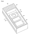
- FIG. 2 is a view showing a state where an upper portion of a casing 200 of microphone unit 120 is cut along a plane parallel to system board 110.
- Microphone unit 120 includes casing 200, a first substrate 210, a second substrate 220, a vibrating unit 230, an ASIC (Application Specific Integrated Circuit) 240, and a dummy component 300.
- Vibrating unit 230 includes a diaphragm 232.
- microphone unit 120 in accordance with the present embodiment is, for example, a capacitor microphone, it may be a microphone of another type.
- the first substrate 210 and the second substrate 220 may be configured as a single-piece substrate.
- Diaphragm 232 has a configuration in which, for example, acoustic-electric conversion is performed by a piezoelectric effect using an inorganic piezoelectric thin film or an organic piezoelectric thin film, or a configuration using an electret film.
- diaphragm 232 is not limited to these configurations.
- a microphone substrate configured of the first substrate 210 and the second substrate 220 is made of, for example, a material such as an insulating molding base material, fired ceramics, glass epoxy, and plastic. However, an insulating material other than those may be used.
- Diaphragm 232 vibrates in an normal direction in response to entry of an acoustic wave. Vibrating unit 230 outputs an electric signal in accordance with a sound entering diaphragm 232.
- Diaphragm 232 can be a diaphragm of microphones of various types such as electrodynamic (dynamic), electromagnetic (magnetic), and piezoelectric (crystal) microphones.
- diaphragm 232 may be a diaphragm of a semiconductor film (for example, a silicon film) or a silicon microphone (Si microphone). By using a silicon microphone, microphone unit 120 can be downsized and can have higher performance. It should be noted that the shape of diaphragm 232 is not particularly limited. For example, the outer shape of diaphragm 232 may be circular, elliptical, polygonal, or the like.
- Dummy component 300 corrects acoustic transmission characteristics in an internal space of casing 200. For example, by reducing the volume of the internal space when compared with a case where dummy component 300 is not provided to casing 200, dummy component 300 shifts a resonance frequency in the internal space to a high range. Thereby, a band having flat frequency characteristics is widened, and acoustic characteristics can be improved.
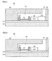
- FIG. 3 is a view showing a state where microphone unit 120 is cut along a plane perpendicular to system board 110.
- Casing 200 is configured to surround vibrating unit 230, diaphragm 232, ASIC 240, and dummy component 300.
- Dummy component 300 is attached to the first substrate 210 to be located below opening 130.
- Diaphragm 232 is arranged to be offset from opening 130. With such an arrangement, even if microscopic objects such as dust enter from opening 130, they are less likely to reach diaphragm 232, and thus they are less likely to affect the vibration of diaphragm 232.
- dummy component 300 is made of, for example, resin or an insulator other than that.
- dummy component 300 can be fixed to a ground potential through the first substrate 210.
- dummy component 300 may be made of a conductive material. Thereby, the effect of electromagnetic shield can be enhanced.
- Dummy component 300 is fitted in a wall surface of casing 200, or in the first substrate 210. With the fit-in structure, dummy component 300 can be accurately positioned relative to the casing. In another aspect, dummy component 300 may be solder-bonded to the first substrate 210.
- An internal space 310 is formed inside microphone unit 120, that is, inside casing 200. Internal space 310 is primarily formed by the presence of a misalignment (offset) between vibrating unit 230 and opening 130.
- offset misalignment
- the first substrate 210 constituting internal space 310 is manufactured, for example, by pressing a mold having a convex portion onto an insulating molding base material, or with fired ceramics using a desired mold. Further, in another aspect, the first substrate 210 can also be manufactured by laminating a substrate having a through hole and a substrate not having a through hole, in plural.
- FIG. 4 is a schematic view of a configuration of microphone unit 400 not having dummy component 300.
- Microphone unit 400 includes casing 200, the first substrate 210, the second substrate 220, vibrating unit 230, diaphragm 232, and ASIC 240.
- a dummy component is not included in microphone unit 400.
- a sound provided from opening 130 resonates inside casing 200.
- an internal space 410 of casing 200 has a larger volume, its resonance frequency is lower than the resonance frequency in the case where casing 200 has a small internal space.
- FIG. 5 is a view showing the resonance frequency in each of cases where the volume inside casing 200 is large and where the volume inside casing 200 is small.
- a graph 510 corresponds, for example, to characteristics of the resonance frequency in the case of microphone unit 400 shown in Fig. 4 .
- a graph 520 corresponds to characteristics of the resonance frequency in the case of microphone unit 120 in accordance with the present embodiment.
- Internal space 410 of microphone unit 400 is larger than internal space 310 of microphone unit 120, at least by the volume of dummy component 300. As a result, the resonance frequency in microphone unit 400 is lower than the resonance frequency in microphone unit 120.
- internal space 310 has a volume smaller than the volume of internal space 410.
- the frequency characteristics shown as indicated by graph 510 change as indicated by graph 520. That is, the resonance frequency becomes higher, and flat frequency characteristics extend to a high range. As a result, acoustic characteristics of mobile phone 100 using microphone unit 120 in accordance with the present embodiment are improved.
- Fig. 5 illustrates that an intersection point of graphs 510 and 520 has a frequency of 10 KHz, and that the resonance frequency in graph 510 has a value of 7 to 8 KHz. These values are merely by way of example, and each value may vary depending on the configuration of the microphone unit.
- a microphone unit 600 in accordance with the present embodiment is different from microphone unit 120 in accordance with the first embodiment described above in that microphone unit 600 is a so-called differential microphone.
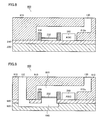
- FIG. 6 is a schematic view of a cross sectional structure of microphone unit 600.
- Microphone unit 600 includes a casing 610, a first substrate 620, a second substrate 630, vibrating unit 230, diaphragm 232, ASIC 240, and dummy component 300. Openings 130, 132 are provided in a front surface of casing 610. A sound passing through opening 130 propagates through a portion above dummy component 300 and ASIC 240 (that is, "internal space 310"), and vibrates an upper surface of diaphragm 232.
- a sound entering from opening 132 passes through an opening provided in the first substrate 620, then through a transmission path provided between the first substrate 620 and the second substrate 630 (that is, an internal space 640), and vibrates a rear surface of diaphragm 232.
- internal space 310 of microphone unit 600 has a volume substantially identical to the volume of internal space 640.
- a distance from opening 130 to diaphragm 232 and a distance from opening 132 to diaphragm 232, that is, respective propagation times, are identical.
- a noise propagating through internal space 310 cancels a noise propagating through internal space 640, and thus diaphragm 232 vibrates with the noises being cancelled.
- frequency characteristics from opening 130 to diaphragm 232 are balanced and matched with frequency characteristics from opening 132 to diaphragm 232, because, if they are not balanced, characteristics as a differential microphone, for example, the effect of suppressing a distant noise, are deteriorated.
- FIG. 7 is a schematic view of a configuration of microphone unit 700 not having a dummy component.
- Microphone unit 700 includes casing 610, the first substrate 620, the second substrate 630, vibrating unit 230, diaphragm 232, and ASIC 240. Openings 130, 132 are provided in casing 610.
- microphone unit 700 does not have a dummy component inside casing 610, internal space 410 through which a sound entering from opening 130 propagates has a volume larger than the volume of internal space 640 of microphone unit 600 provided with dummy component 300. Thus, a resonance frequency in microphone unit 700 is lower than a resonance frequency in microphone unit 600 of Fig. 6 .
- microphone unit 600 in accordance with the present embodiment, since a volume portion of a space is reduced by dummy component 300, the resonance frequency becomes higher. As a result, acoustic characteristics necessary for a mobile phone can be ensured.
- FIG. 8 is a schematic view of a cross sectional configuration of a microphone unit 800 in accordance with the present variation.
- Microphone unit 800 includes a casing 810, the first substrate 210, the second substrate 220, vibrating unit 230, diaphragm 232, and ASIC 240.
- a protruding portion 810a is formed on a surface below opening 130. A sound entering from opening 130 passes through an internal space 820, and vibrates diaphragm 232.
- Protruding portion 810a is formed, for example, by injection-molding casing 810. Such a protruding portion 810a reduces the volume of the internal space of casing 810 as with dummy component 300 described above. Therefore, microphone unit 800 has a resonance frequency higher than the resonance frequency in microphone unit 400 not having protruding portion 810a ( Fig. 4 ). As a result, acoustic characteristics of the mobile phone are improved.
- FIG. 9 is a schematic view of a cross sectional configuration of a microphone unit 900 in accordance with the present variation.
- Microphone unit 900 includes a casing 910, the first substrate 620, the second substrate 630, vibrating unit 230, diaphragm 232, and ASIC 240.
- Microphone unit 900 is a so-called differential microphone. Therefore, a sound entering from opening 130 passes through internal space 820 having a volume reduced by protruding portion 810a, and vibrates diaphragm 232 from the upper surface of diaphragm 232. On the other hand, a sound entering from opening 132 passes through a transmission path formed between the first substrate 620 and the second substrate 630, and vibrates diaphragm 232 from the lower surface of diaphragm 232.
- a transmission path for the sound entering from opening 130 has a volume smaller than that in a case where protruding portion 810a is not provided, and thus a reduction in the resonance frequency can be prevented, and acoustic characteristics of a mobile phone mounted with microphone unit 900 can be improved.
- internal space 820 has a volume substantially identical to the volume of internal space 640.
- the casing of the microphone unit is generally produced by bonding two or more members subjected to a hole drilling process beforehand.
- casing 810 can be formed by processing a single member, and thus casing 810 can be readily processed, and the effects of a reduction in the number of steps and a reduction in cost can be obtained.
- the volume of the internal space of the casing is reduced by dummy component 300 or protruding portion 810a provided in the internal space.
- the resonance frequency shifts to a high range, and a range having flat frequency characteristics is increased.
- acoustic characteristics of equipment provided with the microphone unit for example, a mobile phone, a voice recorder, and the like
- 100 mobile phone, 110: system board, 120, 400, 600, 700, 800, 900: microphone unit, 130, 132: opening, 200, 810: casing, 210, 620: the first substrate, 220, 630: the second substrate, 230: vibrating unit, 232: diaphragm, 240: ASIC, 300: dummy component, 3 10, 410, 640: internal space, 810a: protruding portion.
Landscapes
- Health & Medical Sciences (AREA)
- Otolaryngology (AREA)
- Physics & Mathematics (AREA)
- Engineering & Computer Science (AREA)
- Acoustics & Sound (AREA)
- Signal Processing (AREA)
- Telephone Set Structure (AREA)
- Details Of Audible-Bandwidth Transducers (AREA)
- Electrostatic, Electromagnetic, Magneto- Strictive, And Variable-Resistance Transducers (AREA)
- Obtaining Desirable Characteristics In Audible-Bandwidth Transducers (AREA)
Abstract
Description
- The present invention relates to a microphone unit, and particularly to improvement in acoustic characteristics of a microphone unit.
- During a conversation over the phone or the like, sound recognition, sound recording, and the like, it is preferable to collect only a target sound (a speaker's voice). However, in an environment in which a sound input device for sound collection is used, a sound other than the target sound, such as a background noise, may exist. Thus, sound input devices having a function that allows a target sound to be accurately extracted even when the devices are used in an environment in which a noise exists, that is, a function of removing a noise, are under development. In addition, recently, electronic equipment has been downsized, and the sound input devices have also been downsized.
- Concerning the sound input devices (hereinafter also referred to as "microphones"), for example, Japanese Patent Laying-Open No.
06-339192 - In addition, Japanese Patent Laying-Open No.
08-098289 - Japanese Patent Laying-Open No.
2007-060228 cavity 7, and by placing insulating plate 6 on the rear surface of casing 5, through hole 6a, groove 5a, and opening 5b serve as avent hole 8 connectingcavity 7 with an external space" ([Means for Solution] in [Abstract]). - Japanese Patent Laying-Open No.
2001-054195 semiconductor element 8 are housed in a concave portion 9a of a box-shaped case 9 made of an insulating material, and a rear chamber 12 is provided in a wall surface of concave portion 9a" ([Means for Solution] in [Abstract]). - Japanese Patent Laying-Open No.
2003-163996 semiconductor element 8 are housed in a concave portion 9a of a box-shaped case 9 made of an insulating material, and a rear chamber 12 is provided in a wall surface of concave portion 9a" ([Means for Solution] in [Abstract]). -
- Patent Document 1: Japanese Patent Laying-Open No.
06-339192 - Patent Document 2: Japanese Patent Laying-Open No.
08-098289 - Patent Document 3: Japanese Patent Laying-Open No.
2007-060228 - Patent Document 4: Japanese Patent Laying-Open No.
2001-054195 - Patent Document 5: Japanese Patent Laying-Open No.
2003-163996 - Generally, a microphone unit includes a casing portion including an internal space, a diaphragm arranged inside the internal space to convert acoustic vibration into an electric signal, an amplifier portion amplifying and outputting the electric signal, and an opening provided in the casing portion to connect the internal space with an external space.
- In the microphone unit having such a configuration, the diaphragm is not arranged immediately below the opening, and is arranged to be offset such that the diaphragm does not overlap with a portion immediately below the opening (a portion inside the casing), in order to avoid a malfunction caused by dust entering from the opening from which a sound is input and adhering onto the diaphragm. If the diaphragm is arranged immediately below the opening, the length of a path from the opening to the diaphragm, that is, a propagation time, is minimum, and the volume of the internal space can be minimized. However, if the diaphragm is arranged to be offset from the opening, a certain length of the path and a certain volume of the internal space exist in a portion from the opening to the diaphragm. The internal space configures a system that resonates acoustically. A resonance frequency fo in the space is determined depending on the length of the path from the opening to the diaphragm, the volume and shape of the internal space, and the like.
- In order to keep frequency characteristics of a microphone flat up to a high range, it is desirable to set the resonance frequency in the internal space to a high value. For that purpose, it is necessary to design the internal space to have a volume as small as possible. However, the diaphragm has a support portion supporting the periphery to maintain its strength, with a certain thickness (for example, about 0.4 mm). Thus, for example, if an opening is provided in an upper portion of a box-shaped casing, and the diaphragm is arranged on a bottom portion of an internal space of the casing to be offset from the opening, the internal space at least requires a thickness as the sum of the thickness of the support portion and a thickness of an acoustic path for transmitting a sound input from the opening to the diaphragm (for example, about 0.3 mm). Therefore, a useless space exists below the opening, beside the diaphragm and the support portion. A thickness of 0.3 mm is sufficient for acoustic transmission, while a thickness of 0.7 mm below the opening is useless, increases the volume of the internal space, and leads to a reduction in resonance frequency fo, thus narrowing a flat frequency band and deteriorating the frequency characteristics of the microphone.
- Consequently, a microphone unit with a small size and improved acoustic characteristics is needed. In another aspect, a microphone unit having more flat frequency characteristics is needed. In another aspect, a mobile phone with a small size and improved acoustic characteristics is needed.
- A microphone unit according to an embodiment includes: a casing having an internal space and an opening; a vibrating portion arranged in the internal space to convert acoustic vibration into an electric signal; and an acoustic correction member arranged inside the internal space to correct characteristics of acoustic transmission from the opening to the diaphragm.
- Preferably, the internal space includes a first partial space and a second partial space. The vibrating portion is arranged between the first partial space and the second partial space. A second opening connected to the second partial space is further formed in the casing portion. The acoustic correction member is placed in at least one of the first partial space and the second partial space.
- Preferably, the acoustic correction member is formed such that an air volume of the first partial space is equal to an air volume of the second partial space.
- Preferably, the acoustic correction member has a shape formed such that an acoustic impedance from the first opening to the vibrating portion is equal to an acoustic impedance from the second opening to the vibrating portion.
- Preferably, the vibrating portion is arranged to be offset from a central axis of the opening.
- Preferably, the acoustic correction member is arranged below the opening.
- Preferably, the acoustic correction member is an insulator.
- Preferably, the acoustic correction member is formed of a conductive material and fixed to a ground potential.
- Preferably, the acoustic correction member is fitted in the casing.
- Preferably, the microphone unit further includes a substrate. The acoustic correction member is solder-bonded to the substrate.
- According to another embodiment, a mobile phone provided with any of the microphone units described above is provided.
- With a microphone unit according to an embodiment, more flat frequency characteristics are achieved, and acoustic characteristics are improved. According to another embodiment, a mobile phone in which more flat frequency characteristics are achieved and acoustic characteristics are improved is provided.
- The foregoing and other objects, features, aspects and advantages of the present invention will become apparent from the following detailed description of the present invention when taken in conjunction with the accompanying drawings.
-
-
Fig. 1 is a schematic view of a configuration of amobile phone 100 using amicrophone unit 120 in accordance with a first embodiment. -
Fig. 2 is a view showing a state where an upper portion of acasing 200 ofmicrophone unit 120 is cut along a plane parallel to asystem board 110. -
Fig. 3 is a view showing a state wheremicrophone unit 120 is cut along a plane perpendicular tosystem board 110. -
Fig. 4 is a schematic view of a configuration of amicrophone unit 400 not having adummy component 300. -
Fig. 5 is a view showing frequency characteristics of a resonance frequency in a case where an internal space ofcasing 200 has a large volume and frequency characteristics thereof in a case where the internal space has a small volume. -
Fig. 6 is a schematic view of a cross sectional structure of amicrophone unit 600 in accordance with a second embodiment. -
Fig. 7 is a schematic view of a configuration of amicrophone unit 700 not having a dummy component. -
Fig. 8 is a schematic view of a cross sectional configuration of amicrophone unit 800 in accordance with a first variation of the embodiment. -
Fig. 9 is a schematic view of a cross sectional configuration of amicrophone unit 900 in accordance with a second variation of the embodiment. - Hereinafter, embodiments of the present invention will be described with reference to the drawings. In the description below, identical parts will be designated by the same reference numerals. Since their names and functions are also the same, the detailed description thereof will not be repeated.
- Referring to
Fig. 1 , a mode of use of a microphone unit in accordance with a first embodiment will be described.Fig. 1 is a schematic view of a configuration of amobile phone 100 using amicrophone unit 120.Mobile phone 100 includes asystem board 110.System board 110 includesmicrophone unit 120.Microphone unit 120 includes anopening 130.System board 110 is mounted with a circuit element for implementing an operation ofmobile phone 100. - Referring to
Fig. 2 , a configuration ofmicrophone unit 120 in accordance with the first embodiment will be described.Fig. 2 is a view showing a state where an upper portion of acasing 200 ofmicrophone unit 120 is cut along a plane parallel tosystem board 110.Microphone unit 120 includescasing 200, afirst substrate 210, asecond substrate 220, a vibratingunit 230, an ASIC (Application Specific Integrated Circuit) 240, and adummy component 300. Vibratingunit 230 includes adiaphragm 232. Althoughmicrophone unit 120 in accordance with the present embodiment is, for example, a capacitor microphone, it may be a microphone of another type. Thefirst substrate 210 and thesecond substrate 220 may be configured as a single-piece substrate. -
Diaphragm 232 has a configuration in which, for example, acoustic-electric conversion is performed by a piezoelectric effect using an inorganic piezoelectric thin film or an organic piezoelectric thin film, or a configuration using an electret film. However,diaphragm 232 is not limited to these configurations. A microphone substrate configured of thefirst substrate 210 and thesecond substrate 220 is made of, for example, a material such as an insulating molding base material, fired ceramics, glass epoxy, and plastic. However, an insulating material other than those may be used. -
Diaphragm 232 vibrates in an normal direction in response to entry of an acoustic wave. Vibratingunit 230 outputs an electric signal in accordance with asound entering diaphragm 232.Diaphragm 232 can be a diaphragm of microphones of various types such as electrodynamic (dynamic), electromagnetic (magnetic), and piezoelectric (crystal) microphones. - Alternatively,
diaphragm 232 may be a diaphragm of a semiconductor film (for example, a silicon film) or a silicon microphone (Si microphone). By using a silicon microphone,microphone unit 120 can be downsized and can have higher performance. It should be noted that the shape ofdiaphragm 232 is not particularly limited. For example, the outer shape ofdiaphragm 232 may be circular, elliptical, polygonal, or the like. -
Dummy component 300 corrects acoustic transmission characteristics in an internal space ofcasing 200. For example, by reducing the volume of the internal space when compared with a case wheredummy component 300 is not provided tocasing 200,dummy component 300 shifts a resonance frequency in the internal space to a high range. Thereby, a band having flat frequency characteristics is widened, and acoustic characteristics can be improved. - Referring to
Fig. 3 , the configuration ofmicrophone unit 120 will further be described.Fig. 3 is a view showing a state wheremicrophone unit 120 is cut along a plane perpendicular tosystem board 110. Casing 200 is configured to surround vibratingunit 230,diaphragm 232,ASIC 240, anddummy component 300.Dummy component 300 is attached to thefirst substrate 210 to be located belowopening 130.Diaphragm 232 is arranged to be offset from opening 130. With such an arrangement, even if microscopic objects such as dust enter from opening 130, they are less likely to reachdiaphragm 232, and thus they are less likely to affect the vibration ofdiaphragm 232. - In an aspect,
dummy component 300 is made of, for example, resin or an insulator other than that. In another aspect,dummy component 300 can be fixed to a ground potential through thefirst substrate 210. In this case,dummy component 300 may be made of a conductive material. Thereby, the effect of electromagnetic shield can be enhanced. -
Dummy component 300 is fitted in a wall surface ofcasing 200, or in thefirst substrate 210. With the fit-in structure,dummy component 300 can be accurately positioned relative to the casing. In another aspect,dummy component 300 may be solder-bonded to thefirst substrate 210. - An
internal space 310 is formed insidemicrophone unit 120, that is, insidecasing 200.Internal space 310 is primarily formed by the presence of a misalignment (offset) between vibratingunit 230 andopening 130. - The
first substrate 210 constitutinginternal space 310 is manufactured, for example, by pressing a mold having a convex portion onto an insulating molding base material, or with fired ceramics using a desired mold. Further, in another aspect, thefirst substrate 210 can also be manufactured by laminating a substrate having a through hole and a substrate not having a through hole, in plural. - Next, referring to
Fig. 4 , amicrophone unit 400 in accordance with another aspect will be described.Fig. 4 is a schematic view of a configuration ofmicrophone unit 400 not havingdummy component 300.Microphone unit 400 includescasing 200, thefirst substrate 210, thesecond substrate 220, vibratingunit 230,diaphragm 232, andASIC 240. A dummy component is not included inmicrophone unit 400. - In
microphone unit 400 having the configuration shown inFig. 4 , a sound provided from opening 130 resonates insidecasing 200. In that case, since aninternal space 410 ofcasing 200 has a larger volume, its resonance frequency is lower than the resonance frequency in the case wherecasing 200 has a small internal space. - Thus, referring to
Fig. 5 , the relationship between the volume insidecasing 200 and the resonance frequency will be described.Fig. 5 is a view showing the resonance frequency in each of cases where the volume insidecasing 200 is large and where the volume insidecasing 200 is small. - A
graph 510 corresponds, for example, to characteristics of the resonance frequency in the case ofmicrophone unit 400 shown inFig. 4 . Agraph 520 corresponds to characteristics of the resonance frequency in the case ofmicrophone unit 120 in accordance with the present embodiment. -
Internal space 410 ofmicrophone unit 400 is larger thaninternal space 310 ofmicrophone unit 120, at least by the volume ofdummy component 300. As a result, the resonance frequency inmicrophone unit 400 is lower than the resonance frequency inmicrophone unit 120. However, whendummy component 300 is attached to the inside ofcasing 200 as shown inFig. 3 ,internal space 310 has a volume smaller than the volume ofinternal space 410. As a result, the frequency characteristics shown as indicated bygraph 510 change as indicated bygraph 520. That is, the resonance frequency becomes higher, and flat frequency characteristics extend to a high range. As a result, acoustic characteristics ofmobile phone 100 usingmicrophone unit 120 in accordance with the present embodiment are improved. -
Fig. 5 illustrates that an intersection point ofgraphs graph 510 has a value of 7 to 8 KHz. These values are merely by way of example, and each value may vary depending on the configuration of the microphone unit. - Hereinafter, a second embodiment will be described. A
microphone unit 600 in accordance with the present embodiment is different frommicrophone unit 120 in accordance with the first embodiment described above in thatmicrophone unit 600 is a so-called differential microphone. - Referring to
Fig. 6 , a configuration ofmicrophone unit 600 in accordance with the present embodiment will be described.Fig. 6 is a schematic view of a cross sectional structure ofmicrophone unit 600.Microphone unit 600 includes acasing 610, afirst substrate 620, asecond substrate 630, vibratingunit 230,diaphragm 232,ASIC 240, anddummy component 300.Openings casing 610. A sound passing throughopening 130 propagates through a portion abovedummy component 300 and ASIC 240 (that is, "internal space 310"), and vibrates an upper surface ofdiaphragm 232. On the other hand, a sound entering from opening 132 passes through an opening provided in thefirst substrate 620, then through a transmission path provided between thefirst substrate 620 and the second substrate 630 (that is, an internal space 640), and vibrates a rear surface ofdiaphragm 232. - Preferably, in the example shown in
Fig. 6 ,internal space 310 ofmicrophone unit 600 has a volume substantially identical to the volume ofinternal space 640. In addition, a distance from opening 130 todiaphragm 232 and a distance from opening 132 todiaphragm 232, that is, respective propagation times, are identical. In this case, a noise propagating throughinternal space 310 cancels a noise propagating throughinternal space 640, and thus diaphragm 232 vibrates with the noises being cancelled. - As a result, higher-quality acoustic characteristics can be obtained.
- Here, it is desirable that, in a frequency band in use, frequency characteristics from opening 130 to diaphragm 232 are balanced and matched with frequency characteristics from opening 132 to
diaphragm 232, because, if they are not balanced, characteristics as a differential microphone, for example, the effect of suppressing a distant noise, are deteriorated. - Referring to
Fig. 7 , amicrophone unit 700 in accordance with another aspect will be described.Fig. 7 is a schematic view of a configuration ofmicrophone unit 700 not having a dummy component.Microphone unit 700 includescasing 610, thefirst substrate 620, thesecond substrate 630, vibratingunit 230,diaphragm 232, andASIC 240.Openings casing 610. - Since
microphone unit 700 does not have a dummy component insidecasing 610,internal space 410 through which a sound entering from opening 130 propagates has a volume larger than the volume ofinternal space 640 ofmicrophone unit 600 provided withdummy component 300. Thus, a resonance frequency inmicrophone unit 700 is lower than a resonance frequency inmicrophone unit 600 ofFig. 6 . - However, according to
microphone unit 600 in accordance with the present embodiment, since a volume portion of a space is reduced bydummy component 300, the resonance frequency becomes higher. As a result, acoustic characteristics necessary for a mobile phone can be ensured. - In addition, fine adjustment for changing the size of the dummy component in accordance with sensitivity in
internal space 640 and obtaining high-quality differential characteristics can be performed. - Referring to
Fig. 8 , a first variation of the present embodiment will be described.Fig. 8 is a schematic view of a cross sectional configuration of amicrophone unit 800 in accordance with the present variation.Microphone unit 800 includes acasing 810, thefirst substrate 210, thesecond substrate 220, vibratingunit 230,diaphragm 232, andASIC 240. In a configuration ofcasing 810, a protrudingportion 810a is formed on a surface belowopening 130. A sound entering from opening 130 passes through aninternal space 820, and vibratesdiaphragm 232. - Protruding
portion 810a is formed, for example, by injection-molding casing 810. Such a protrudingportion 810a reduces the volume of the internal space ofcasing 810 as withdummy component 300 described above. Therefore,microphone unit 800 has a resonance frequency higher than the resonance frequency inmicrophone unit 400 not having protrudingportion 810a (Fig. 4 ). As a result, acoustic characteristics of the mobile phone are improved. - Referring to
Fig. 9 , a second variation of the present embodiment will be described.Fig. 9 is a schematic view of a cross sectional configuration of amicrophone unit 900 in accordance with the present variation.Microphone unit 900 includes acasing 910, thefirst substrate 620, thesecond substrate 630, vibratingunit 230,diaphragm 232, andASIC 240. - In
casing 910, protrudingportion 810a is formed belowopening 130.Microphone unit 900 is a so-called differential microphone. Therefore, a sound entering from opening 130 passes throughinternal space 820 having a volume reduced by protrudingportion 810a, and vibratesdiaphragm 232 from the upper surface ofdiaphragm 232. On the other hand, a sound entering from opening 132 passes through a transmission path formed between thefirst substrate 620 and thesecond substrate 630, and vibratesdiaphragm 232 from the lower surface ofdiaphragm 232. With this configuration, a transmission path for the sound entering from opening 130 has a volume smaller than that in a case where protrudingportion 810a is not provided, and thus a reduction in the resonance frequency can be prevented, and acoustic characteristics of a mobile phone mounted withmicrophone unit 900 can be improved. In this case, it is desirable thatinternal space 820 has a volume substantially identical to the volume ofinternal space 640. With such a configuration,microphone unit 900 can cancel noises as a differential microphone. - Concerning the first variation and the second variation, since it is difficult to form a lateral acoustic path inside
casing 810, the casing of the microphone unit is generally produced by bonding two or more members subjected to a hole drilling process beforehand. However, according to the configuration in whichdummy component 300 is arranged as inmicrophone unit 800 in accordance with the first variation ormicrophone unit 900 in accordance with the second variation, casing 810 can be formed by processing a single member, and thus casing 810 can be readily processed, and the effects of a reduction in the number of steps and a reduction in cost can be obtained. - As has been described in detail, according to the microphone unit in accordance with each embodiment or its variation, the volume of the internal space of the casing is reduced by
dummy component 300 or protrudingportion 810a provided in the internal space. As a result, the resonance frequency shifts to a high range, and a range having flat frequency characteristics is increased. Thereby, acoustic characteristics of equipment provided with the microphone unit (for example, a mobile phone, a voice recorder, and the like) can be improved. - Although the embodiments of the present invention have been described and illustrated in detail, it is clearly understood that the same is by way of illustration and example only and is not to be taken by way of limitation, the scope of the present invention being interpreted by the terms of the appended claims
- 100: mobile phone, 110: system board, 120, 400, 600, 700, 800, 900: microphone unit, 130, 132: opening, 200, 810: casing, 210, 620: the first substrate, 220, 630: the second substrate, 230: vibrating unit, 232: diaphragm, 240: ASIC, 300: dummy component, 3 10, 410, 640: internal space, 810a: protruding portion.
Claims (11)
- A microphone unit, comprising:a casing having an internal space and a first opening;a vibrating portion arranged in said internal space to convert acoustic vibration into an electric signal; andan acoustic correction member arranged inside said internal space to correct characteristics of acoustic transmission from said first opening to the diaphragm.
- The microphone unit according to claim 1, wherein
said internal space includes a first partial space and a second partial space, said vibrating portion is arranged between the first partial space and the second partial space,
a second opening connected to the second partial space is further formed in said casing portion,
said first opening is connected to said first partial space, and
said acoustic correction member is placed in at least one of said first partial space and said second partial space. - The microphone unit according to claim 2, wherein said acoustic correction member is formed such that an air volume of the first partial space is equal to an air volume of the second partial space.
- The microphone unit according to claim 2, wherein said acoustic correction member has a shape formed such that an acoustic impedance from said first opening to said vibrating portion is equal to an acoustic impedance from said second opening to said vibrating portion.
- The microphone unit according to claim 1, wherein said vibrating portion is arranged to be offset from a central axis of said first opening.
- The microphone unit according to claim 1, wherein said acoustic correction member is arranged below said first opening.
- The microphone unit according to claim 1, wherein said acoustic correction member is an insulator.
- The microphone unit according to claim 1, wherein said acoustic correction member is formed of a conductive material and fixed to a ground potential.
- The microphone unit according to claim 1, wherein said acoustic correction member is fitted in said casing.
- The microphone unit according to claim 1, further comprising a substrate, wherein said acoustic correction member is solder-bonded to said substrate.
- A mobile phone provided with the microphone unit according to claim 1.
Applications Claiming Priority (2)
| Application Number | Priority Date | Filing Date | Title |
|---|---|---|---|
| JP2008196540A JP5200737B2 (en) | 2008-07-30 | 2008-07-30 | Differential microphone unit |
| PCT/JP2009/062904 WO2010013603A1 (en) | 2008-07-30 | 2009-07-16 | Microphone unit and cellular phone provided with same |
Publications (2)
| Publication Number | Publication Date |
|---|---|
| EP2323421A1 true EP2323421A1 (en) | 2011-05-18 |
| EP2323421A4 EP2323421A4 (en) | 2013-03-13 |
Family
ID=41610302
Family Applications (1)
| Application Number | Title | Priority Date | Filing Date |
|---|---|---|---|
| EP20090802846 Withdrawn EP2323421A4 (en) | 2008-07-30 | 2009-07-16 | Microphone unit and cellular phone provided with same |
Country Status (6)
| Country | Link |
|---|---|
| US (1) | US8565465B2 (en) |
| EP (1) | EP2323421A4 (en) |
| JP (1) | JP5200737B2 (en) |
| CN (1) | CN102113344B (en) |
| TW (1) | TW201026087A (en) |
| WO (1) | WO2010013603A1 (en) |
Families Citing this family (17)
| Publication number | Priority date | Publication date | Assignee | Title |
|---|---|---|---|---|
| JP2011114506A (en) * | 2009-11-26 | 2011-06-09 | Funai Electric Co Ltd | Microphone unit |
| EP2517481A4 (en) * | 2009-12-22 | 2015-06-03 | Mh Acoustics Llc | SURFACE MOUNTED MICROPHONE ARRAYS ON FLEXIBLE PRINTED CIRCUIT BOARDS |
| JP5636795B2 (en) * | 2010-08-02 | 2014-12-10 | 船井電機株式会社 | Microphone unit |
| JP5636796B2 (en) * | 2010-08-02 | 2014-12-10 | 船井電機株式会社 | Microphone unit |
| KR102008374B1 (en) * | 2012-08-03 | 2019-10-23 | 삼성전자주식회사 | Input device for portable terminal |
| JP2014158140A (en) * | 2013-02-15 | 2014-08-28 | Funai Electric Co Ltd | Voice input device |
| EP3158776B1 (en) | 2014-06-23 | 2019-05-01 | TDK Corporation | Microphone and method of manufacturing a microphone |
| CN105657627A (en) * | 2014-11-11 | 2016-06-08 | 晶镁电子股份有限公司 | Electronic device having dust-proof function and method for manufacturing the same |
| KR20160072587A (en) * | 2014-12-15 | 2016-06-23 | 삼성전자주식회사 | Acoustic input module and electronic device including the same |
| US20170240418A1 (en) * | 2016-02-18 | 2017-08-24 | Knowles Electronics, Llc | Low-cost miniature mems vibration sensor |
| JP2018033084A (en) * | 2016-08-26 | 2018-03-01 | 京セラ株式会社 | Electronic apparatus |
| DE102018207605B9 (en) | 2018-05-16 | 2024-07-04 | Infineon Technologies Ag | MEMS sensor, MEMS sensor system and method for producing a MEMS sensor system |
| JP6718155B2 (en) * | 2018-09-28 | 2020-07-08 | Tdk株式会社 | Microphone and method of manufacturing a microphone |
| CN110868680B (en) * | 2019-11-01 | 2025-02-21 | 钰太芯微电子科技(上海)有限公司 | Microphone structure with improved substrate |
| CN218679381U (en) * | 2020-06-30 | 2023-03-21 | 瑞声声学科技(深圳)有限公司 | Vibration sensor |
| US20220046361A1 (en) * | 2020-08-07 | 2022-02-10 | Apple Inc. | Mobile device having a tubular microphone integrated into a cover assembly |
| WO2023015486A1 (en) * | 2021-08-11 | 2023-02-16 | 深圳市韶音科技有限公司 | Microphone |
Family Cites Families (14)
| Publication number | Priority date | Publication date | Assignee | Title |
|---|---|---|---|---|
| JPH06339192A (en) | 1993-05-27 | 1994-12-06 | Atsuden Kk | Microphone unit |
| US5511130A (en) * | 1994-05-04 | 1996-04-23 | At&T Corp. | Single diaphragm second order differential microphone assembly |
| JPH0898289A (en) | 1994-09-28 | 1996-04-12 | Oki Electric Ind Co Ltd | Ground-based microphone and method of manufacturing the same |
| JPH10257583A (en) * | 1997-03-06 | 1998-09-25 | Asahi Chem Ind Co Ltd | Voice processing device and voice processing method |
| US6633647B1 (en) * | 1997-06-30 | 2003-10-14 | Hewlett-Packard Development Company, L.P. | Method of custom designing directional responses for a microphone of a portable computer |
| JP3389536B2 (en) | 1999-08-11 | 2003-03-24 | 京セラ株式会社 | Electret condenser microphone |
| TW518900B (en) | 2001-09-11 | 2003-01-21 | Ind Tech Res Inst | Structure of electret silicon capacitive type microphone and method for making the same |
| US7136500B2 (en) * | 2003-08-05 | 2006-11-14 | Knowles Electronics, Llc. | Electret condenser microphone |
| US7233679B2 (en) | 2003-09-30 | 2007-06-19 | Motorola, Inc. | Microphone system for a communication device |
| DE102004011149B3 (en) | 2004-03-08 | 2005-11-10 | Infineon Technologies Ag | Microphone and method of making a microphone |
| JP2005295278A (en) * | 2004-03-31 | 2005-10-20 | Hosiden Corp | Microphone device |
| JP2007060228A (en) | 2005-08-24 | 2007-03-08 | Matsushita Electric Works Ltd | Silicon microphone package |
| US20080130935A1 (en) | 2006-09-27 | 2008-06-05 | Yamaha Corporation | Microphone package |
| JP2008109649A (en) * | 2006-09-27 | 2008-05-08 | Yamaha Corp | Microphone package |
-
2008
- 2008-07-30 JP JP2008196540A patent/JP5200737B2/en not_active Expired - Fee Related
-
2009
- 2009-07-16 EP EP20090802846 patent/EP2323421A4/en not_active Withdrawn
- 2009-07-16 US US13/056,513 patent/US8565465B2/en not_active Expired - Fee Related
- 2009-07-16 WO PCT/JP2009/062904 patent/WO2010013603A1/en not_active Ceased
- 2009-07-16 CN CN200980130235.XA patent/CN102113344B/en not_active Expired - Fee Related
- 2009-07-24 TW TW098125060A patent/TW201026087A/en unknown
Also Published As
| Publication number | Publication date |
|---|---|
| US20110195745A1 (en) | 2011-08-11 |
| CN102113344B (en) | 2016-01-27 |
| TW201026087A (en) | 2010-07-01 |
| JP2010034991A (en) | 2010-02-12 |
| CN102113344A (en) | 2011-06-29 |
| EP2323421A4 (en) | 2013-03-13 |
| JP5200737B2 (en) | 2013-06-05 |
| WO2010013603A1 (en) | 2010-02-04 |
| US8565465B2 (en) | 2013-10-22 |
Similar Documents
| Publication | Publication Date | Title |
|---|---|---|
| US8565465B2 (en) | Microphone unit and mobile phone provided with the same | |
| US10399850B2 (en) | Transducer with enlarged back volume | |
| CN102239704B (en) | Microphone unit | |
| US9521499B2 (en) | Electronic device with large back volume for electromechanical transducer | |
| KR101697786B1 (en) | Microphone | |
| US10567868B2 (en) | Sound generator | |
| GB2629728A (en) | Dual membrane piezoelectric microelectromechanical system microphone | |
| US8649545B2 (en) | Microphone unit | |
| EP2587834A1 (en) | Microphone unit | |
| US20130028459A1 (en) | Monolithic Silicon Microphone | |
| US20080273736A1 (en) | Electrostatic microphone | |
| US12185055B2 (en) | Multi-cavity packaging for microelectromechanical system microphones | |
| US12200431B2 (en) | Sound pickup device | |
| WO2022100551A1 (en) | Mems piezoelectric microspeaker, microspeaker unit, and electronic device | |
| US20200377363A1 (en) | Packaging for mems transducers | |
| US9357313B2 (en) | Microphone unit having a plurality of diaphragms and a signal processing unit | |
| US9420365B2 (en) | Silicon condenser microphone | |
| JP5419254B2 (en) | Microphone unit | |
| JP4812378B2 (en) | Condenser microphone | |
| KR102726900B1 (en) | High-sensitivity all-in-one noise canceling microphone device for automobiles |
Legal Events
| Date | Code | Title | Description |
|---|---|---|---|
| PUAI | Public reference made under article 153(3) epc to a published international application that has entered the european phase |
Free format text: ORIGINAL CODE: 0009012 |
|
| 17P | Request for examination filed |
Effective date: 20110225 |
|
| AK | Designated contracting states |
Kind code of ref document: A1 Designated state(s): AT BE BG CH CY CZ DE DK EE ES FI FR GB GR HR HU IE IS IT LI LT LU LV MC MK MT NL NO PL PT RO SE SI SK SM TR |
|
| AX | Request for extension of the european patent |
Extension state: AL BA RS |
|
| DAX | Request for extension of the european patent (deleted) | ||
| A4 | Supplementary search report drawn up and despatched |
Effective date: 20130213 |
|
| RIC1 | Information provided on ipc code assigned before grant |
Ipc: H04M 1/03 20060101ALI20130207BHEP Ipc: H04R 1/38 20060101AFI20130207BHEP |
|
| 17Q | First examination report despatched |
Effective date: 20140226 |
|
| RAP1 | Party data changed (applicant data changed or rights of an application transferred) |
Owner name: FUNAI ELECTRIC CO., LTD. |
|
| APBK | Appeal reference recorded |
Free format text: ORIGINAL CODE: EPIDOSNREFNE |
|
| APBN | Date of receipt of notice of appeal recorded |
Free format text: ORIGINAL CODE: EPIDOSNNOA2E |
|
| APBR | Date of receipt of statement of grounds of appeal recorded |
Free format text: ORIGINAL CODE: EPIDOSNNOA3E |
|
| RAP1 | Party data changed (applicant data changed or rights of an application transferred) |
Owner name: ONPA TECHNOLOGIES INC. |
|
| APAF | Appeal reference modified |
Free format text: ORIGINAL CODE: EPIDOSCREFNE |
|
| APBT | Appeal procedure closed |
Free format text: ORIGINAL CODE: EPIDOSNNOA9E |
|
| STAA | Information on the status of an ep patent application or granted ep patent |
Free format text: STATUS: THE APPLICATION IS DEEMED TO BE WITHDRAWN |
|
| 18D | Application deemed to be withdrawn |
Effective date: 20180201 |