EP2323156A2 - Ceramic tube for high-intensity discharge lamp and method of producing the same - Google Patents
Ceramic tube for high-intensity discharge lamp and method of producing the same Download PDFInfo
- Publication number
- EP2323156A2 EP2323156A2 EP10190963A EP10190963A EP2323156A2 EP 2323156 A2 EP2323156 A2 EP 2323156A2 EP 10190963 A EP10190963 A EP 10190963A EP 10190963 A EP10190963 A EP 10190963A EP 2323156 A2 EP2323156 A2 EP 2323156A2
- Authority
- EP
- European Patent Office
- Prior art keywords
- plug member
- hollow member
- ceramic tube
- wall
- closure
- Prior art date
- Legal status (The legal status is an assumption and is not a legal conclusion. Google has not performed a legal analysis and makes no representation as to the accuracy of the status listed.)
- Withdrawn
Links
- 239000000919 ceramic Substances 0.000 title claims abstract description 53
- 238000000034 method Methods 0.000 title claims description 33
- 238000003780 insertion Methods 0.000 claims abstract description 87
- 230000037431 insertion Effects 0.000 claims abstract description 87
- 230000003247 decreasing effect Effects 0.000 claims abstract description 16
- 238000002834 transmittance Methods 0.000 claims description 62
- 238000005266 casting Methods 0.000 claims description 9
- 239000000463 material Substances 0.000 claims description 4
- 238000009826 distribution Methods 0.000 description 17
- 239000002002 slurry Substances 0.000 description 15
- 238000010304 firing Methods 0.000 description 11
- CPLXHLVBOLITMK-UHFFFAOYSA-N Magnesium oxide Chemical compound [Mg]=O CPLXHLVBOLITMK-UHFFFAOYSA-N 0.000 description 8
- MCMNRKCIXSYSNV-UHFFFAOYSA-N Zirconium dioxide Chemical compound O=[Zr]=O MCMNRKCIXSYSNV-UHFFFAOYSA-N 0.000 description 8
- 239000000843 powder Substances 0.000 description 8
- 230000000694 effects Effects 0.000 description 6
- 229910001507 metal halide Inorganic materials 0.000 description 6
- 150000005309 metal halides Chemical class 0.000 description 6
- 238000000149 argon plasma sintering Methods 0.000 description 4
- 238000001354 calcination Methods 0.000 description 4
- 230000000052 comparative effect Effects 0.000 description 4
- 239000000395 magnesium oxide Substances 0.000 description 4
- RUDFQVOCFDJEEF-UHFFFAOYSA-N yttrium(III) oxide Inorganic materials [O-2].[O-2].[O-2].[Y+3].[Y+3] RUDFQVOCFDJEEF-UHFFFAOYSA-N 0.000 description 4
- PNEYBMLMFCGWSK-UHFFFAOYSA-N Alumina Chemical compound [O-2].[O-2].[O-2].[Al+3].[Al+3] PNEYBMLMFCGWSK-UHFFFAOYSA-N 0.000 description 3
- LYCAIKOWRPUZTN-UHFFFAOYSA-N Ethylene glycol Chemical compound OCCO LYCAIKOWRPUZTN-UHFFFAOYSA-N 0.000 description 3
- 239000011347 resin Substances 0.000 description 3
- 229920005989 resin Polymers 0.000 description 3
- 230000015572 biosynthetic process Effects 0.000 description 2
- 239000002612 dispersion medium Substances 0.000 description 2
- 230000004313 glare Effects 0.000 description 2
- 238000002156 mixing Methods 0.000 description 2
- 239000002245 particle Substances 0.000 description 2
- 238000002360 preparation method Methods 0.000 description 2
- 239000011164 primary particle Substances 0.000 description 2
- 239000002994 raw material Substances 0.000 description 2
- XLYOFNOQVPJJNP-UHFFFAOYSA-N water Substances O XLYOFNOQVPJJNP-UHFFFAOYSA-N 0.000 description 2
- ADQQGJLCEXHTRW-UHFFFAOYSA-N 1-(dimethylamino)hexan-1-ol Chemical compound CCCCCC(O)N(C)C ADQQGJLCEXHTRW-UHFFFAOYSA-N 0.000 description 1
- 229910000838 Al alloy Inorganic materials 0.000 description 1
- UFHFLCQGNIYNRP-UHFFFAOYSA-N Hydrogen Chemical compound [H][H] UFHFLCQGNIYNRP-UHFFFAOYSA-N 0.000 description 1
- 230000006399 behavior Effects 0.000 description 1
- 239000011230 binding agent Substances 0.000 description 1
- 239000003054 catalyst Substances 0.000 description 1
- 238000005336 cracking Methods 0.000 description 1
- 230000006866 deterioration Effects 0.000 description 1
- XTDYIOOONNVFMA-UHFFFAOYSA-N dimethyl pentanedioate Chemical compound COC(=O)CCCC(=O)OC XTDYIOOONNVFMA-UHFFFAOYSA-N 0.000 description 1
- 239000002270 dispersing agent Substances 0.000 description 1
- 230000005684 electric field Effects 0.000 description 1
- 238000001125 extrusion Methods 0.000 description 1
- 239000003349 gelling agent Substances 0.000 description 1
- 238000005469 granulation Methods 0.000 description 1
- 230000003179 granulation Effects 0.000 description 1
- 229910052739 hydrogen Inorganic materials 0.000 description 1
- 239000001257 hydrogen Substances 0.000 description 1
- 238000010348 incorporation Methods 0.000 description 1
- 238000002347 injection Methods 0.000 description 1
- 239000007924 injection Substances 0.000 description 1
- 239000007788 liquid Substances 0.000 description 1
- 238000004519 manufacturing process Methods 0.000 description 1
- 229910052751 metal Inorganic materials 0.000 description 1
- 239000002184 metal Substances 0.000 description 1
- 239000011369 resultant mixture Substances 0.000 description 1
- 230000035939 shock Effects 0.000 description 1
- 238000005245 sintering Methods 0.000 description 1
- 239000007787 solid Substances 0.000 description 1
- 238000007711 solidification Methods 0.000 description 1
- 230000008023 solidification Effects 0.000 description 1
- 239000007921 spray Substances 0.000 description 1
- 239000004094 surface-active agent Substances 0.000 description 1
Images






Classifications
-
- H—ELECTRICITY
- H01—ELECTRIC ELEMENTS
- H01J—ELECTRIC DISCHARGE TUBES OR DISCHARGE LAMPS
- H01J61/00—Gas-discharge or vapour-discharge lamps
- H01J61/02—Details
- H01J61/30—Vessels; Containers
-
- H—ELECTRICITY
- H01—ELECTRIC ELEMENTS
- H01J—ELECTRIC DISCHARGE TUBES OR DISCHARGE LAMPS
- H01J61/00—Gas-discharge or vapour-discharge lamps
- H01J61/02—Details
- H01J61/36—Seals between parts of vessels; Seals for leading-in conductors; Leading-in conductors
- H01J61/361—Seals between parts of vessel
- H01J61/363—End-disc seals or plug seals
-
- H—ELECTRICITY
- H01—ELECTRIC ELEMENTS
- H01J—ELECTRIC DISCHARGE TUBES OR DISCHARGE LAMPS
- H01J9/00—Apparatus or processes specially adapted for the manufacture, installation, removal, maintenance of electric discharge tubes, discharge lamps, or parts thereof; Recovery of material from discharge tubes or lamps
- H01J9/24—Manufacture or joining of vessels, leading-in conductors or bases
- H01J9/245—Manufacture or joining of vessels, leading-in conductors or bases specially adapted for gas discharge tubes or lamps
- H01J9/247—Manufacture or joining of vessels, leading-in conductors or bases specially adapted for gas discharge tubes or lamps specially adapted for gas-discharge lamps
Definitions
- the present invention relates to a ceramic tube for a high-intensity discharge lamp obtained by inserting a plug member into a hollow member and by subjecting the members to a firing treatment, and to a method of producing the ceramic tube for a high-intensity discharge lamp.
- a tube 1 is shown as an example of such tubes.
- the tube 1 is produced by assembling a hollow member 3 and a plug member 4.
- the hollow member 3 has an insertion opening 2 at one end and a bottom at the other end, and the plug member 4 is inserted into the insertion opening 2.
- the hollow member 3 contains a substantially cylindrical body 5, a closure 6 for closing one end of the body 5, and a long first electrode insert 7 protruding from one surface of the closure 6.
- the plug member 4 contains a disc-shaped portion 8 and a long second electrode insert 9 protruding from one surface thereof.
- the side wall of the disc-shaped portion 8 is bonded to the inner wall of the insertion opening 2.
- the hollow member 3 and the plug member 4 having such structures are generally composed of a translucent alumina ceramic.
- a pair of electrodes (not shown) are inserted into insertion holes 10, 11.
- the insertion opening 2 in the tube 1 generally has a constant diameter in the vicinity of the open end which the disc-shaped portion 8 is inserted to.
- the disc-shaped portion 8 is often bonded in the inclined state to the insertion opening 2 as shown in FIG. 10 .
- This inclination is caused due to the irregularity of positions in which the bonding between the hollow member 3 and the disc-shaped portion 8 is started in the step of sintering and gradually shrinking the hollow member 3.
- the bonding of the disc-shaped portion 8 is started not in a position in the vicinity of the inside of the insertion opening 2 but in a position in the vicinity of the inlet side of the insertion opening 2, the hollow member 3 is shrunk in the axis direction toward the bonded position in the vicinity of the inlet side until also the position in the vicinity of the inside is bonded by further shrinkage.
- the bonding of the disc-shaped portion 8 is started in a position in the vicinity of the inside of the insertion opening 2, the hollow member 3 is shrunk in the axis direction toward the bonded position in the vicinity of the inside of the insertion opening 2.
- the ends of the hollow member 3 and the disc-shaped portion 8 are bonded at approximately the same height in the point in which the bonding is started in the vicinity of the inlet side, while the end of the disc-shaped portion 8 protrudes from the hollow member 3 in the point in which the bonding is started in the vicinity of the inside, so that the disc-shaped portion 8 is inclined.
- the axis of the second electrode insert 9 in the plug member 4 is inclined from the axis of the first electrode insert 7 in the hollow member 3.
- the electrodes inserted in the insertion holes 10, 11 are not arranged facing each other on a common axis. This may cause the breakage of the member in a process of inserting the electrodes to produce a lamp, and may increase the discharge instability of the lamp. Furthermore, the discharge arc position variation is disadvantageously increased due to the position instability of the electrodes, resulting in difficulty in light distribution control.
- the bonding may be started in a position in the vicinity of the inlet side and in a position in the vicinity of the inside of the insertion opening 2, and then the intermediate position may be bonded thereafter.
- a closed space is formed between the bonded positions, air remains in the space, and a cavity is formed in the space in the bonding process, thereby resulting in the generation of a scattered light causing glare and the deterioration of a lamp life.
- the plug member 4 is prepared by a press forming method, since the disc-shaped portion 8 tends to have a smaller diameter in the intermediate position, this problem is often caused.
- the closure 6 of the hollow member 3 and the disc-shaped portion 8 of the plug member 4 have the same in-line transmittance lower than that of the body 5 of the hollow member 3, and a light is mainly emitted from the body 5. Therefore, for example, when the tube 1 is used in combination with a reflecting mirror to form a lamp for emitting a light in one direction, the light cannot be emitted in the axis direction of the reflecting mirror disadvantageously, resulting in difficulty in light distribution control.
- Japanese Laid-Open Patent Publication No. 2006-093046 discloses a tube with an improved light distribution property.
- the tube is obtained by assembling three members, and wherein a portion corresponding to the body of the hollow member and a portion corresponding to the disc-shaped portion of the plug member (or the closure of the hollow member) have different transmittances.
- this tube cannot emit a light in the axis direction.
- a general object of the present invention is to provide a ceramic tube for a high-intensity discharge lamp, which can reduce the breakage of a member in the production.
- a principal object of the present invention is to provide a ceramic tube for a high-intensity discharge lamp, which can be easily equipped with electrodes facing each other.
- Another object of the present invention is to provide a ceramic tube for a high-intensity discharge lamp, which can prevent the generation of glare due to a scattered light.
- a further object of the present invention is to provide a ceramic tube for high-intensity discharge lamp, which can be easily controlled in terms of light distribution.
- a ceramic tube for a high-intensity discharge lamp comprising a hollow member and a plug member each containing an electrode insert, to which an electrode is inserted, wherein the hollow member contains a substantially cylindrical body, an opening at one end of the body and a closure for closing another end of the body, the plug member is inserted into the opening, before the insertion of the plug member, the opening has a tapered portion with a diameter decreasing in a direction from an inlet to an inside of the hollow member at least in an area into which the plug member is inserted, and after the insertion of the plug member, an outer wall of the plug member is bonded to an inner wall of the opening.
- the bonding is generally started in a position in the vicinity of the inside of the opening because the inner wall of the opening and the outer wall of the plug member are spaced at a small interval in the position in the vicinity of the inside of the opening. Then, the hollow member is shrunk in the axis direction toward the inside on the entire circumference until the plug member is bonded also in the vicinity of the inlet of the opening to complete the bonding. Therefore, the above described inclination of the plug member can be prevented.
- the electrode inserts face each other on a common axis, whereby the electrodes can be easily arranged facing each other in the inserts.
- the axes of the electrodes can be easily prevented from being misaligned.
- the axis of the electrode insert in the hollow member can be aligned with the axis of the electrode insert in the plug member inserted into the insertion opening. Therefore, the electrodes can be easily arranged facing each other in the inserts, and an arc can be obtained with stable position and shape.
- the bonding proceeds in the direction from the inside to the open end while pushing air out, whereby cavities are not formed in an intermediate position on the outer wall of the plug member.
- the remaining of air can be prevented in the closure of the hollow member, and the formation of cavity can be prevented in the connection, whereby the generation of a scattered light can be reduced.
- the light distribution can be easily controlled.
- the plug member contains a disc-shaped portion with a substantially constant outer diameter, the above-mentioned advantageous effects are improved particularly remarkably.
- an inner wall of the tapered portion is at an angle of 0.5° to 4° to the outer wall of the disc-shaped portion.
- a corresponding tapered portion with a diameter decreasing correspondingly with the above tapered portion is formed on the outer wall of the body.
- the thickness of the hollow member can be reduced, so that the size and weight of the hollow member (or the ceramic tube for a high-intensity discharge lamp) can be reduced.
- a chamfer is disposed between the outer wall of the body and an outer wall of the closure.
- a corresponding chamfer is formed in a mold.
- the mold having the corresponding chamfer can be more easily filled with a slurry as compared with a right-angled mold.
- the generation of air bubbles is prevented in the slurry, whereby a light from the resultant hollow member can be easily controlled with respect to the distribution without scattering.
- the hollow member and the plug member have different in-line transmittances.
- the body and closure in the hollow member and the disc-shaped portion in the plug member have different in-line transmittances, the light distribution can be easily controlled.
- the different in-line transmittances may be obtained by using a press forming method for preparing the plug member and by using a gel casting method for preparing the hollow member.
- the gel casting method is capable of forming a compact with a more uniform ceramic particle density distribution as compared with the press forming method.
- all parts of the compact can be shrunk at an approximately uniform shrinkage rate to prevent incorporation of fine air bubbles.
- sintered compact has a dense structure and a high in-line transmittance.
- At least the hollow member may be prepared from a material with a high transmittance described in Japanese Patent Application No. 2009-207941 , etc., to obtain more remarkable effects.
- the hollow member has an in-line transmittance higher than that of the plug member. In this case, the light distribution can be controlled more easily.
- the different in-line transmittances may be obtained by using the body, the closure, and the disc-shaped portion of the plug member having different thicknesses.
- the closure may have a thickness smaller than that of the plug member (particularly the disc-shaped portion).
- the closure has an in-line transmittance higher than that of the plug member.
- the in-line transmittance is increased in the order of the plug member (the disc-shaped portion), the closure, and the body, and the resultant ceramic tube can be easily used in combination with a reflecting mirror to emit a light in one direction. It is difficult to reduce the thickness of the hollow member or to increase the thickness difference in the hollow member in a press or injection forming method. Therefore, the hollow member is preferably prepared by the gel casting method.
- the closure may have a thickness larger than that of the disc-shaped portion of the plug member conversely.
- the hollow member has an in-line transmittance lower than that of the plug member.
- a method of producing a ceramic tube for a high-intensity discharge lamp comprising a hollow member and a plug member each containing an electrode insert, to which an electrode is inserted, wherein the hollow member contains a substantially cylindrical body, an opening at one end of the body and a closure for closing another end of the body, the plug member is inserted into the opening, wherein the hollow member has a tapered, diameter-decreasing portion with a diameter decreasing in a direction from an inlet of the opening for the plug member to an inside of the hollow member at least in an area into which the plug member is inserted, wherein the plug member has a disc-shaped portion with a substantially constant outer diameter, and wherein an inner wall of the tapered, diameter-decreasing portion is at an angle of 0.5° to 4° to an outer wall of the disc-shaped portion of the plug member, the method comprising the steps of:
- the plug member can be prevented from inclining.
- the ceramic tube for a high-intensity discharge lamp may be hereinafter referred to simply as the tube.
- FIG. 1 is a schematic longitudinal cross-sectional view showing a hollow member 22 and a plug member 26 for producing a tube 20 according to this embodiment.
- the hollow member 22 has an insertion opening 24 and a bottom, and the plug member 26 is inserted into the insertion opening 24.
- the hollow member 22 may be a compact or calcine having a shrinkage allowance.
- the plug member 26 may be a calcine, or alternatively may be a compact having a controlled density and a shrinkage allowance smaller than that of the hollow member 22.
- the hollow member 22 contains a substantially bowl-shaped body 28, a closure 29 for closing one end of the body 28, and a long first electrode insert 30 protruding from one surface of the closure 29.
- An insertion hole 32 is formed in the first electrode insert 30, and a first electrode 34 is introduced into the insertion hole 32 as described hereinafter (see FIG. 7 ).
- the insertion opening 24 has a tapered portion 36 with a diameter gradually decreasing in the direction from the open end to the inside (see FIG. 1 ).
- a disc-shaped portion 46 in the plug member 26 is introduced from the open end.
- the taper angle ⁇ of the tapered portion 36 in the insertion opening 24 is preferably 0.5° to 4°, more preferably 0.5° to 2°.
- the insertion opening 24 has a bottom 38 with a flat surface.
- the outer diameter of the disc-shaped portion 46 is 1% to 10% larger than the inner diameter of the insertion opening 24 in the fired members.
- the body 28 and the plug member 26 inserted into the insertion opening 24 are simultaneously fired, they are firmly bonded by a pressure generated due to the dimensional difference.
- the tapered portion 36 has an excessively large taper angle ⁇ , the shrink fitting ratio difference between the open end and the inside of the insertion opening 24 is increased, so that the bonding may be insufficient in the vicinity of the open end, or the disc-shaped portion 46 may be excessively fitted into the insertion opening 24, generating a crack in the vicinity of the inside, disadvantageously.
- the taper angle ⁇ is less than 0.5°, it is difficult to prevent the inclination of the plug member 26 and the formation of a cavity in the connection. Therefore, the taper angle ⁇ is preferably within the above range.
- a corresponding tapered portion 40 with a diameter gradually decreasing in correspondence with the tapered portion 36 is formed on the outer wall of the body 28.
- the diameter of the outer wall of the body 28 is decreased with the diameter reduction of the insertion opening 24.
- the thickness T of the body 28 i.e. the distance between the inner and outer walls of the insertion opening 24 in the body 28) is approximately uniform in the entire body 28.
- the outer wall of the closure 29 is tapered in the direction from the body 28 toward the first electrode insert 30.
- the taper angle ⁇ of the closure 29 (the angle between the direction in which the closure 29 extends and the direction in which the first electrode insert 30 extends) is preferably 75° to 85°.
- a greatly tapered portion with a taper angle larger than that of the corresponding tapered portion 40 is formed on the closure 29 in an area from the tapered portion 36 to the first electrode insert 30.
- a chamfer 44 is disposed between the closure 29 and the body 28. That is, the closure 29 and the body 28 are connected by the chamfer 44.
- the advantageous effects can be obtained not only in the case of gradually reducing the inner diameter of the insertion opening 24 in the hollow member 22 but also in the case of gradually reducing the outer diameter of the disc-shaped portion 46 in the plug member 26 to form a tapered shape.
- the bonding is started in a position at a sharp angle, and an excessively high stress is applied to the insertion opening 24 in the shrink fitting.
- the connection may be cracked or chipped due to the high stress.
- the disc-shaped portion 46 preferably has a constant outer diameter (within an error range of plus or minus 0.5°) to prevent the problem.
- An insertion hole 50 is formed in the second electrode insert 48, and a second electrode 52 is introduced into the insertion hole 50 (see FIG. 7 ).
- the materials of the hollow member 22 and the plug member 26 have different transmittances.
- the body 28 and the closure 29 in the hollow member 22 are different in in-line transmittance from the disc-shaped portion 46 in the plug member 26. It is preferred that the plug member 26 has a transmittance lower than that of the hollow member 22.
- the different transmittances may be obtained by making the closure 29 in the hollow member 22 thinner than the disc-shaped portion 46 in the plug member 26.
- the thickness of the body 28 is preferably 0.7 mm or less, more preferably 0.5 mm or less.
- the thickness ratio between the thick and thin portions is preferably 2/1 or more, more preferably 3/1 or more.
- the tube 20 having the above structure may be produced as follows.
- the hollow member 22 may be prepared by a gel casting method.
- a powder of a ceramic or the like for the hollow member 22 is dispersed in a dispersive liquid such as water to prepare a slurry, and the slurry is cast to a mold and hardened therein.
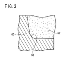
- the chamfer 44 is disposed between the closure 29 and the body 28. Therefore, as shown in FIG. 3 , a chamfer 66 is formed also in a mold 60. A slurry 62 flows along the chamfer 66, so that the mold 60 is sufficiently filled with the slurry 62. Thus, the air bubble generation and the light scattering in the hollow member 22 can be prevented in the embodiment.
- the closure 29 preferably has a taper angle ⁇ of 75° to 85°.
- the taper angle ⁇ is less than 75°, the heat capacity of the closure 29 is increased, and the lamp efficiency is deteriorated.
- the taper angle ⁇ is more than 85°, it is difficult to prevent the air bubble generation.
- the plug member 26 may be prepared by a press forming method. Of course it may be prepared by a gel casting method.
- the plug member 26 When the outer diameter of the disc-shaped portion 46 in the prepared plug member 26 is larger than the inner diameter of the insertion opening 24 in the hollow member 22, the plug member 26 is subjected to a calcination treatment. The plug member 26 is sintered and sufficiently shrunk by the calcination treatment. When the firing shrinkage ratio of the plug member 26 is controlled, and the outer diameter of the disc-shaped portion 46 is smaller than the inner diameter of the insertion opening 24, the calcination treatment is not required.
- the disc-shaped portion 46 of the plug member 26 is inserted into the insertion opening 24 of the hollow member 22 to prepare an assembly for producing the tube 20.
- the diameter of the disc-shaped portion 46 is smaller than the diameter of the open end of the insertion opening 24, and the the insertion opening 24 has the tapered portion 36 with the decreasing diameter.
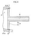
- the disc-shaped portion 46 is in contact with the inner wall of the insertion opening 24 in inside positions represented by black points ( ⁇ ) in the cross-sectional view of FIG. 4 , and the bonding is started in the inside positions.
- the disc-shaped portion 46 and the body 28 are positioned and fixed by the contact and bonding.
- the shrinkage of the hollow member 22 is continued even after the bonding is started.
- the body 28 is shrunk in the axis direction toward the inside positions represented by the black points ( ⁇ ) in FIG. 4 , in which the members are positioned and fixed by the bonding.
- the bonded region is expanded from the positions (the inside of the insertion opening 24) toward the open end.
- the entire outer wall of the plug member 26 is bonded to the inner wall of the hollow member 22 by the circumferential shrinkage to obtain a bonded assembly.
- a firing shrinkage force against the plug member 26 is relatively great.
- the firing shrinkage force against the plug member 26 is relatively low.
- the bonded assembly is subjected to a firing treatment in this state.
- the side wall of the disc-shaped portion 46 and the inner wall of the insertion opening 24, in surface contact with each other, are integrated in the process of the firing treatment.
- the bonding of the side wall of the plug member 26 to the inner wall of the insertion opening 24 is completed to produce the tube 20.
- the tapered portion 36 with the decreasing diameter remains in the tube 20 (see FIG. 5 ).
- the first electrode insert 30 and the second electrode insert 48 face each other. In other words, they are aligned on a common axis.
- the disc-shaped portion 46 is brought into contact with the inner wall of the insertion opening 24 (the tapered portion 36) in the inside positions represented by the black points ( ⁇ ) in FIG. 4 , the first electrode insert 30 and the second electrode insert 48 are aligned on a common axis. Then the bonding proceeds in the direction from the inside to the open end gradually, whereby the disc-shaped portion 46 is bonded to the inner wall of the insertion opening 24.
- a cavity is not formed in the connection of the tube 20. This is because air is not contained in the closed connection as described above.
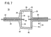
- the first electrode 34 is inserted into the first electrode insert 30, and the second electrode 52 is inserted into the second electrode insert 48, to obtain a ceramic metal halide lamp 70. Since the first electrode insert 30 and the second electrode insert 48 are aligned on a common axis as described above, the first electrode 34 and the second electrode 52 face each other on a common axis.
- the first electrode 34 and the second electrode 52 can be arranged facing each other in this manner.
- the ceramic metal halide lamp 70 an electric field is applied between the first electrode 34 and the second electrode 52 to ionize a metal halide contained in the insertion opening 24.
- the discharge emission can be obtained with the ionization.
- an air bubble is hardly generated in the hollow member 22, and a cavity is hardly formed in the connection as described above.
- the hollow member 22 contains few air bubbles, and the connection contains few cavities.
- the tube 20 can be prevented from cracking from the air bubble or cavity due to a thermal shock in an emission process, and the lamp 70 can be prevented from being deteriorated in life due to leak.
- the light scattering due to the air bubble or cavity can be prevented.
- An appropriate light distribution can be effectively obtained by preventing the light scattering because the light distribution is deteriorated by a scattered light.
- the light distribution can be easily controlled.
- the light distribution control can be easily carried out by utilizing the in-line transmittance difference without attaching a light shielding film, a metal plate, etc. for removing a glare-causing part from the emitted light.
- the chamfer 44 When the chamfer 44 is disposed (a curved portion is formed) between the body 28 and the closure 29, the light scattering can be further reduced, whereby the light distribution can be preferably further improved.
- the hollow member 22 may have a thickness smaller than that of the plug member 26 differently from the above embodiment. In this case, the transmittance of the hollow member 22 is increased, and a light emission from the hollow member 22 can be easily utilized. Furthermore, a light emission from the plug member 26 is reduced, and the light distribution can be improved.
- the ceramic tube of the present invention includes a tube 86 shown in FIG. 8 produced by combining a substantially semielliptical hollow member 80 and a plug member 84.
- the plug member 84 contains a curved closure 82 having a curved concave surface facing an insertion opening 24 of the hollow member 80.
- the ceramic tube of the present invention includes a tube 92 shown in FIG. 9 containing a hollow member 90 having a particular closure 29.
- the inner wall of the closure 29 (a bottom 38 of an insertion opening 24) has a diameter decreasing in the direction toward a first electrode insert 30 to form a tapered shape.
- a first electrode 34 is disposed at a large distance from the inner wall of the closure 29 (the bottom 38 of the insertion opening 24).
- the tube 92 has an approximately uniform temperature distribution, and the color temperature is advantageously stabilized to improve the lamp characteristics.
- the slurry was cast into an aluminum alloy mold at the room temperature.
- the slurry was left in the mold at the room temperature for 1 hour and at 40°C for 30 minutes to perform the solidification.
- the resultant solid was separated from the mold, and was let stand at the room temperature for 2 hours and at 90°C for 2 hours, to obtain the hollow member 22.
- the insertion opening 24 had a taper angle ⁇ of 0.5° in an area to be bonded to the plug member 26, the closure 29 had a taper angle ⁇ of 85°, the chamfer 44 was formed between the body 28 and the closure 29, and the body 28 had a thickness of 0.5 mm.
- a slurry was prepared by mixing the following components to obtain a powder for forming the plug member 26.
- the granulated powder was press-formed under a pressure of 1000 kg/cm 2 to obtain the plug member 26.
- the disc-shaped portion 46 had a constant outer diameter and a thickness of 1.5 mm.
- the sizes of the hollow member 22 and the plug member 26 were controlled such that when the hollow member 22 and the plug member 26 were separately fired, the outer diameter of the disc-shaped portion 46 is 1.001 to 1.010 times larger than the inner diameter of the insertion opening 24 in the fired members.
- the plug member 26 was calcined and shrunk at 1200°C, and the disc-shaped portion 46 was inserted into the insertion opening of the hollow member 22 to obtain an assembly.
- the hollow member 22 was shrunk by calcining the assembly at 1200°C, whereby the hollow member 22 and the plug member 26 were bonded to obtain a bonded assembly.
- the bonded assembly was fired at 1800°C in a hydrogen atmosphere, whereby the hollow member 22 and the plug member 26 were integrated to obtain the ceramic tube 20 for a high-intensity discharge lamp.
- the first electrode insert 30 and the second electrode insert 48 had a coaxiality of 0.3 mm. Cavities were not formed in the connection of the tube 20, and air bubbles were not observed in the closure 29 of the hollow member 22.
- the in-line transmittance of each part of the tube 20 was measured.
- the disc-shaped portion 46 had an in-line transmittance of 1% or less, and a light was hardly transferred therethrough.
- the body 28 had an in-line transmittance of 15%, and the closure 29 had an in-line transmittance of 8%. Scattered lights were not observed.
- Three ceramic tubes 20 for a high-intensity discharge lamp were produced in the same manner as in Example 1 except that the taper angle ⁇ of the insertion opening 24 in the hollow member 22 was changed to 1°, 2°, and 4°, respectively.
- the first electrode insert 30 and the second electrode insert 48 had a coaxiality of 0.2 mm.
- the cavity ratios of the connections were 0%, 0%, and 10%, respectively. Air bubbles were not observed in the closure 29 of the hollow member 22.
- the in-line transmittance of each part of each tube 20 was measured.
- the disc-shaped portion 46 had an in-line transmittance of 1% or less, and a light was hardly transferred therethrough.
- the body 28 had an in-line transmittance of 15%, and the closure 29 had an in-line transmittance of 8%. Scattered lights were not observed.
- a ceramic tube 20 for a high-intensity discharge lamp was produced in the same manner as in Example 1 except that the taper angle ⁇ of the closure 29 was changed to 75°.
- the first electrode insert 30 and the second electrode insert 48 had a coaxiality of 0.3 mm. Cavities were not formed in the connection of the tube 20, and air bubbles were not observed in the closure 29 of the hollow member 22.
- the in-line transmittance of each part of the tube 20 was measured.
- the disc-shaped portion 46 had an in-line transmittance of 1% or less, and a light was hardly transferred therethrough.
- the body 28 had an in-line transmittance of 15%, and the closure 29 had an in-line transmittance of 8%. Scattered lights were not observed.
- the hollow member 22 was prepared in the same manner as in Example 1, and the plug member 26 was prepared from the slurry for the hollow member 22. Then, the members were assembled and bonded in the same manner as in Example 1 to produce a ceramic tube 20 for a high-intensity discharge lamp.
- the insertion opening 24 had a taper angle of 1°
- the body 28 had a thickness of 0.5 mm
- the closure 29 was formed in an ellipsoid shape.
- the disc-shaped portion 46 in the plug member 26 had a thickness of 1.5 mm.
- the first electrode insert 30 and the second electrode insert 48 had a coaxiality of 0.2 mm. Cavities were not formed in the connection of the tube 20, and air bubbles were not observed in the closure 29 of the hollow member 22.
- the in-line transmittance of each part of the tube 20 was measured.
- the disc-shaped portion 46 had an in-line transmittance of 1% or less, and a light was hardly transferred therethrough.
- both the body 28 and the closure 29 had an in-line transmittance of 15%. Scattered lights were not observed.
- a ceramic tube 20 for a high-intensity discharge lamp was produced in the same manner as in Example 6 except that the thicknesses of the body 28 and the disc-shaped portion 46 were changed to 0.7 and 1.4 mm, respectively.
- the first electrode insert 30 and the second electrode insert 48 had a coaxiality of 0.2 mm. Cavities were not formed in the connection of the tube 20, and air bubbles were not observed in the closure 29 of the hollow member 22.
- the in-line transmittance of each part of the tube 20 was measured.
- the disc-shaped portion 46 had an in-line transmittance of 1% or less, and a light was hardly transferred therethrough.
- both the body 28 and the closure 29 had an in-line transmittance of 10%. Scattered lights were not observed.
- a ceramic tube for a high-intensity discharge lamp was produced in the same manner as in Example 1 except that the insertion opening in the hollow member had a taper angle ⁇ of 0°, the closure in the hollow member had a taper angle ⁇ of 90°, and a chamfer was not formed between the body and the closure.
- the first electrode insert and the second electrode insert had a coaxiality of 0.8 mm.
- the cavity ratio of the connection was 25% based on the entire area, and a plurality of air bubbles were observed in the closure of the hollow member.
- the in-line transmittance of each part of the tube was measured.
- the disc-shaped portion in the plug member had an in-line transmittance of 1% or less
- the body in the hollow member had an in-line transmittance of 15%
- a light was hardly transferred therethrough.
- the in-line transmittance of the closure varied within the range of 0% to 8%, and a scattered light was observed in the closure.
- a ceramic tube for a high-intensity discharge lamp was produced in the same manner as in Example 1 except that the insertion opening in the hollow member had a taper angle of 5°, and the closure in the hollow member had a taper angle of 70°.
- the first electrode insert and the second electrode insert had a coaxiality of 0.2 mm. Significant cavities were formed in the connection particularly in the vicinity of the open end of the insertion opening, and the cavity ratio of the connection was 50% or more based on the entire area. Air bubbles were not observed in the closure of the hollow member.
- the in-line transmittance of each part of the tube was measured.
- the disc-shaped portion had an in-line transmittance of 1% or less, and a light was hardly transferred therethrough.
- the body In the hollow member, the body had an in-line transmittance of 15%, and the closure had an in-line transmittance of lower than 1%. Scattered lights were not observed.
- the present invention relates to a ceramic tube (20) for a high-intensity discharge lamp, comprising a hollow member (22) and a plug member (26).
- the hollow member (22) contains a substantially cylindrical body (28) and a closure (29) for closing one end of the body (28), and the plug member (26) is inserted into an insertion opening (24) formed at the other end of the body (28).
- the insertion opening (24) Before the insertion of the plug member (26), the insertion opening (24) has a tapered portion (36) with a diameter decreasing in the direction from the open end to the inside at least in an area into which the plug member (26) is inserted. After the insertion of the plug member (26), an outer wall of the plug member (26) is bonded to an inner wall of the insertion opening (24).
Landscapes
- Engineering & Computer Science (AREA)
- Manufacturing & Machinery (AREA)
- Vessels And Coating Films For Discharge Lamps (AREA)
- Manufacture Of Electron Tubes, Discharge Lamp Vessels, Lead-In Wires, And The Like (AREA)
Abstract
Description
- The present invention relates to a ceramic tube for a high-intensity discharge lamp obtained by inserting a plug member into a hollow member and by subjecting the members to a firing treatment, and to a method of producing the ceramic tube for a high-intensity discharge lamp.
- In ceramic metal halide lamps, a pair of electrodes are inserted into a ceramic tube for a high-intensity discharge lamp (hereinafter referred to simply as the tube), and a metal halide is ionized by the electrodes to show discharge emission.
- Various examples of such tubes have been disclosed, and include those produced by assembling a plurality of members, those produced integrally as a single member, and those produced by bonding two members. In
FIG. 10 , atube 1 is shown as an example of such tubes. Thetube 1 is produced by assembling ahollow member 3 and aplug member 4. Thehollow member 3 has an insertion opening 2 at one end and a bottom at the other end, and theplug member 4 is inserted into theinsertion opening 2. - In the
tube 1, thehollow member 3 contains a substantiallycylindrical body 5, aclosure 6 for closing one end of thebody 5, and a long first electrode insert 7 protruding from one surface of theclosure 6. Meanwhile, theplug member 4 contains a disc-shaped portion 8 and a long second electrode insert 9 protruding from one surface thereof. The side wall of the disc-shaped portion 8 is bonded to the inner wall of the insertion opening 2. - The
hollow member 3 and theplug member 4 having such structures are generally composed of a translucent alumina ceramic. InFIG. 10 , a pair of electrodes (not shown) are inserted intoinsertion holes - As shown in
FIG. 10 , the first electrode insert 7 (the insertion hole 10) and the second electrode insert 9 (the insertion hole 11) face each other on a common axis. Therefore, the electrodes (not shown) are arranged facing each other in theinsertion holes - As described in Japanese Laid-Open Patent Publication Nos.
2002-117807 10-125230 tube 1 can be obtained by the steps of preparing thehollow member 3 and theplug member 4 separately by extrusion or press forming, firing and shrinking theplug member 4, inserting the disc-shaped portion 8 of theplug member 4 into the open end of the insertion opening 2 in thehollow member 3, and subjecting thehollow member 3 and the insertedplug member 4 to a firing treatment. In the firing treatment, thehollow member 3 is sintered and shrunk, whereby the inner wall of the insertion opening 2 and the side wall of the disc-shaped portion 8 are integrally bonded. - As is clear from
FIG. 2 of Japanese Laid-Open Patent Publication No.2002-117807 FIG. 2 of Japanese Laid-Open Patent Publication No.10-125230 tube 1 generally has a constant diameter in the vicinity of the open end which the disc-shaped portion 8 is inserted to. In such a structure, the disc-shaped portion 8 is often bonded in the inclined state to theinsertion opening 2 as shown inFIG. 10 . - This inclination is caused due to the irregularity of positions in which the bonding between the
hollow member 3 and the disc-shaped portion 8 is started in the step of sintering and gradually shrinking thehollow member 3. Thus, when in a certain point on the circumference, the bonding of the disc-shaped portion 8 is started not in a position in the vicinity of the inside of the insertion opening 2 but in a position in the vicinity of the inlet side of the insertion opening 2, thehollow member 3 is shrunk in the axis direction toward the bonded position in the vicinity of the inlet side until also the position in the vicinity of the inside is bonded by further shrinkage. When in another point on the circumference, the bonding of the disc-shaped portion 8 is started in a position in the vicinity of the inside of the insertion opening 2, thehollow member 3 is shrunk in the axis direction toward the bonded position in the vicinity of the inside of the insertion opening 2. In a case where such different bonding behaviors are simultaneously caused in different points on the circumference, the ends of thehollow member 3 and the disc-shaped portion 8 are bonded at approximately the same height in the point in which the bonding is started in the vicinity of the inlet side, while the end of the disc-shaped portion 8 protrudes from thehollow member 3 in the point in which the bonding is started in the vicinity of the inside, so that the disc-shaped portion 8 is inclined. - In this case, the axis of the second electrode insert 9 in the
plug member 4 is inclined from the axis of thefirst electrode insert 7 in thehollow member 3. Thus, the electrodes inserted in theinsertion holes - In the process of bonding the disc-
shaped portion 8 in theplug member 4 to the insertion opening 2 in thehollow member 3, the bonding may be started in a position in the vicinity of the inlet side and in a position in the vicinity of the inside of the insertion opening 2, and then the intermediate position may be bonded thereafter. In this case, a closed space is formed between the bonded positions, air remains in the space, and a cavity is formed in the space in the bonding process, thereby resulting in the generation of a scattered light causing glare and the deterioration of a lamp life. Particularly, when theplug member 4 is prepared by a press forming method, since the disc-shaped portion 8 tends to have a smaller diameter in the intermediate position, this problem is often caused. - In addition, in the
tube 1, theclosure 6 of thehollow member 3 and the disc-shaped portion 8 of theplug member 4 have the same in-line transmittance lower than that of thebody 5 of thehollow member 3, and a light is mainly emitted from thebody 5. Therefore, for example, when thetube 1 is used in combination with a reflecting mirror to form a lamp for emitting a light in one direction, the light cannot be emitted in the axis direction of the reflecting mirror disadvantageously, resulting in difficulty in light distribution control. - In view of this disadvantage, Japanese Laid-Open Patent Publication No.
2006-093046 - A general object of the present invention is to provide a ceramic tube for a high-intensity discharge lamp, which can reduce the breakage of a member in the production.
- A principal object of the present invention is to provide a ceramic tube for a high-intensity discharge lamp, which can be easily equipped with electrodes facing each other.
- Another object of the present invention is to provide a ceramic tube for a high-intensity discharge lamp, which can prevent the generation of glare due to a scattered light.
- A further object of the present invention is to provide a ceramic tube for high-intensity discharge lamp, which can be easily controlled in terms of light distribution.
- According to an aspect of the present invention, there is provided a ceramic tube for a high-intensity discharge lamp, comprising a hollow member and a plug member each containing an electrode insert, to which an electrode is inserted, wherein
the hollow member contains a substantially cylindrical body, an opening at one end of the body and a closure for closing another end of the body,
the plug member is inserted into the opening,
before the insertion of the plug member, the opening has a tapered portion with a diameter decreasing in a direction from an inlet to an inside of the hollow member at least in an area into which the plug member is inserted, and
after the insertion of the plug member, an outer wall of the plug member is bonded to an inner wall of the opening. - When the plug member is inserted into the insertion opening having the tapered portion, the bonding is generally started in a position in the vicinity of the inside of the opening because the inner wall of the opening and the outer wall of the plug member are spaced at a small interval in the position in the vicinity of the inside of the opening. Then, the hollow member is shrunk in the axis direction toward the inside on the entire circumference until the plug member is bonded also in the vicinity of the inlet of the opening to complete the bonding. Therefore, the above described inclination of the plug member can be prevented.
- Thus, in the present invention, the electrode inserts face each other on a common axis, whereby the electrodes can be easily arranged facing each other in the inserts. In other words, the axes of the electrodes can be easily prevented from being misaligned.
- As described above, in the present invention, since the tapered portion is formed in the insertion opening of the hollow member, the axis of the electrode insert in the hollow member can be aligned with the axis of the electrode insert in the plug member inserted into the insertion opening. Therefore, the electrodes can be easily arranged facing each other in the inserts, and an arc can be obtained with stable position and shape.
- Furthermore, the bonding proceeds in the direction from the inside to the open end while pushing air out, whereby cavities are not formed in an intermediate position on the outer wall of the plug member. Thus, the remaining of air can be prevented in the closure of the hollow member, and the formation of cavity can be prevented in the connection, whereby the generation of a scattered light can be reduced. In addition, when the hollow member and the plug member have different in-line transmittances, the light distribution can be easily controlled.
- In a case where the plug member contains a disc-shaped portion with a substantially constant outer diameter, the above-mentioned advantageous effects are improved particularly remarkably.
- In this case, in view of the above effects, it is preferred that an inner wall of the tapered portion is at an angle of 0.5° to 4° to the outer wall of the disc-shaped portion.
- It is preferred that a corresponding tapered portion with a diameter decreasing correspondingly with the above tapered portion is formed on the outer wall of the body. In this case, the thickness of the hollow member can be reduced, so that the size and weight of the hollow member (or the ceramic tube for a high-intensity discharge lamp) can be reduced.
- It is preferred that a chamfer is disposed between the outer wall of the body and an outer wall of the closure. In the case of using the chamfer, a corresponding chamfer is formed in a mold. The mold having the corresponding chamfer can be more easily filled with a slurry as compared with a right-angled mold. Thus, the generation of air bubbles is prevented in the slurry, whereby a light from the resultant hollow member can be easily controlled with respect to the distribution without scattering.
- It is preferred that the hollow member and the plug member have different in-line transmittances. When the body and closure in the hollow member and the disc-shaped portion in the plug member have different in-line transmittances, the light distribution can be easily controlled.
- For example, the different in-line transmittances may be obtained by using a press forming method for preparing the plug member and by using a gel casting method for preparing the hollow member. The gel casting method is capable of forming a compact with a more uniform ceramic particle density distribution as compared with the press forming method. When the compact with a uniform density distribution is fired, all parts of the compact can be shrunk at an approximately uniform shrinkage rate to prevent incorporation of fine air bubbles. Thus obtained sintered compact has a dense structure and a high in-line transmittance. At least the hollow member may be prepared from a material with a high transmittance described in Japanese Patent Application No.
2009-207941 - It is more preferred that the hollow member has an in-line transmittance higher than that of the plug member. In this case, the light distribution can be controlled more easily.
- Alternatively, the different in-line transmittances may be obtained by using the body, the closure, and the disc-shaped portion of the plug member having different thicknesses.
- Thus, for example, the closure may have a thickness smaller than that of the plug member (particularly the disc-shaped portion). In this case, the closure has an in-line transmittance higher than that of the plug member. In this case, when the body has a thickness smaller than that of the closure, the in-line transmittance is increased in the order of the plug member (the disc-shaped portion), the closure, and the body, and the resultant ceramic tube can be easily used in combination with a reflecting mirror to emit a light in one direction. It is difficult to reduce the thickness of the hollow member or to increase the thickness difference in the hollow member in a press or injection forming method. Therefore, the hollow member is preferably prepared by the gel casting method.
- It is to be understood that the closure may have a thickness larger than that of the disc-shaped portion of the plug member conversely. In this case, the hollow member has an in-line transmittance lower than that of the plug member.
- According to another aspect of the present invention, there is provided a method of producing a ceramic tube for a high-intensity discharge lamp comprising a hollow member and a plug member each containing an electrode insert, to which an electrode is inserted,
wherein the hollow member contains a substantially cylindrical body, an opening at one end of the body and a closure for closing another end of the body, the plug member is inserted into the opening,
wherein the hollow member has a tapered, diameter-decreasing portion with a diameter decreasing in a direction from an inlet of the opening for the plug member to an inside of the hollow member at least in an area into which the plug member is inserted,
wherein the plug member has a disc-shaped portion with a substantially constant outer diameter, and
wherein an inner wall of the tapered, diameter-decreasing portion is at an angle of 0.5° to 4° to an outer wall of the disc-shaped portion of the plug member,
the method comprising the steps of: - inserting the disc-shaped portion to the opening, and
- bonding the outer wall of the plug member to the inner wall of the opening.
- According to the above-mentioned process, the plug member can be prevented from inclining. Thus, it becomes easy to arrange electrodes as well as electrode inserts to face each other coaxially. As a result, it is possible to prevent axial misalignment between electrodes.
- The above and other objects features and advantages of the present invention will become more apparent from the following description when taken in conjunction with the accompanying drawings in which a preferred embodiment of the present invention is shown by way of illustrative example.
-
-
FIG. 1 is a schematic longitudinal cross-sectional view showing a hollow member and a plug member for producing a ceramic tube for a high-intensity discharge lamp according to an embodiment of the present invention, the hollow member having an insertion opening and a bottom, the plug member being inserted into the insertion opening; -
FIG. 2 is a cross-sectional view showing a principal part of a mold having a right-angled portion filled with a slurry; -
FIG. 3 is a cross-sectional view showing a principal part of a mold having a curved portion (a chamfer) filled with a slurry; -
FIG. 4 is an enlarged longitudinal cross-sectional view showing a principal part of the process of bringing the side wall of a disc-shaped portion in the plug member into point contact with the inner wall of the insertion opening in the hollow member; -
FIG. 5 is an enlarged longitudinal cross-sectional view showing a principal part of the process of bonding the side wall of the disc-shaped portion to the inner wall of the insertion opening; -
FIG. 6 is a schematic longitudinal cross-sectional view showing the ceramic tube for a high-intensity discharge lamp, produced by bonding the side wall of the disc-shaped portion to the inner wall of the insertion opening; -
FIG. 7 is a schematic longitudinal cross-sectional view showing a ceramic metal halide lamp produced by inserting a pair of electrodes into the ceramic tube; -
FIG. 8 is a schematic longitudinal cross-sectional view showing a ceramic tube for a high-intensity discharge lamp according to another embodiment of the present invention; -
FIG. 9 is a schematic longitudinal cross-sectional view showing a ceramic tube for a high-intensity discharge lamp according to a further embodiment of the present invention; and -
FIG. 10 is a schematic longitudinal cross-sectional view showing a ceramic tube for a high-intensity discharge lamp according to a related art. - Preferred embodiments of the ceramic tube of the present invention for a high-intensity discharge lamp and the method of producing the same will be described in detail below with reference to the accompanying drawings. The ceramic tube for a high-intensity discharge lamp may be hereinafter referred to simply as the tube.
-
FIG. 1 is a schematic longitudinal cross-sectional view showing ahollow member 22 and aplug member 26 for producing atube 20 according to this embodiment. Thehollow member 22 has aninsertion opening 24 and a bottom, and theplug member 26 is inserted into theinsertion opening 24. InFIG. 1 , thehollow member 22 may be a compact or calcine having a shrinkage allowance. Theplug member 26 may be a calcine, or alternatively may be a compact having a controlled density and a shrinkage allowance smaller than that of thehollow member 22. - The
hollow member 22 contains a substantially bowl-shapedbody 28, aclosure 29 for closing one end of thebody 28, and a longfirst electrode insert 30 protruding from one surface of theclosure 29. Aninsertion hole 32 is formed in thefirst electrode insert 30, and afirst electrode 34 is introduced into theinsertion hole 32 as described hereinafter (seeFIG. 7 ). - An opening is formed at one end of the
body 28 to provide thehollow member 22 with theinsertion opening 24 and a bottom. Theinsertion opening 24 has a taperedportion 36 with a diameter gradually decreasing in the direction from the open end to the inside (seeFIG. 1 ). A disc-shapedportion 46 in theplug member 26 is introduced from the open end. The taper angle α of the taperedportion 36 in theinsertion opening 24 is preferably 0.5° to 4°, more preferably 0.5° to 2°. In this embodiment, theinsertion opening 24 has a bottom 38 with a flat surface. - If the
hollow member 22 and theplug member 26 are separately fired, the outer diameter of the disc-shapedportion 46 is 1% to 10% larger than the inner diameter of theinsertion opening 24 in the fired members. When thebody 28 and theplug member 26 inserted into theinsertion opening 24 are simultaneously fired, they are firmly bonded by a pressure generated due to the dimensional difference. When the taperedportion 36 has an excessively large taper angle α, the shrink fitting ratio difference between the open end and the inside of theinsertion opening 24 is increased, so that the bonding may be insufficient in the vicinity of the open end, or the disc-shapedportion 46 may be excessively fitted into theinsertion opening 24, generating a crack in the vicinity of the inside, disadvantageously. On the other hand, when the taper angle α is less than 0.5°, it is difficult to prevent the inclination of theplug member 26 and the formation of a cavity in the connection. Therefore, the taper angle α is preferably within the above range. - A corresponding tapered
portion 40 with a diameter gradually decreasing in correspondence with the taperedportion 36 is formed on the outer wall of thebody 28. Thus, the diameter of the outer wall of thebody 28 is decreased with the diameter reduction of theinsertion opening 24. The thickness T of the body 28 (i.e. the distance between the inner and outer walls of theinsertion opening 24 in the body 28) is approximately uniform in theentire body 28. - Also, the outer wall of the
closure 29 is tapered in the direction from thebody 28 toward thefirst electrode insert 30. The taper angle θ of the closure 29 (the angle between the direction in which theclosure 29 extends and the direction in which thefirst electrode insert 30 extends) is preferably 75° to 85°. Thus, a greatly tapered portion with a taper angle larger than that of the corresponding taperedportion 40 is formed on theclosure 29 in an area from the taperedportion 36 to thefirst electrode insert 30. Incidentally, achamfer 44 is disposed between theclosure 29 and thebody 28. That is, theclosure 29 and thebody 28 are connected by thechamfer 44. - The
plug member 26 contains the disc-shapedportion 46 and a longsecond electrode insert 48 protruding from one surface thereof. The side wall of the disc-shapedportion 46 is bonded to the inner wall of theinsertion opening 24. The diameter of the disc-shapedportion 46 is constant in the thickness direction. If thehollow member 22 and theplug member 26 are separately fired, the outer diameter of the disc-shapedportion 46 is larger than the inner diameter of theinsertion opening 24 in the fired members. However, theplug member 26 is calcined, or alternatively the firing shrinkage ratio thereof is controlled (reduced to a ratio lower than that of the hollow member 22), so that the outer diameter of the disc-shapedportion 46 is smaller than the inner diameter of the open end of theinsertion opening 24 before the assembling. - The advantageous effects can be obtained not only in the case of gradually reducing the inner diameter of the
insertion opening 24 in thehollow member 22 but also in the case of gradually reducing the outer diameter of the disc-shapedportion 46 in theplug member 26 to form a tapered shape. However, in the latter case, the bonding is started in a position at a sharp angle, and an excessively high stress is applied to theinsertion opening 24 in the shrink fitting. The connection may be cracked or chipped due to the high stress. Thus, the disc-shapedportion 46 preferably has a constant outer diameter (within an error range of plus or minus 0.5°) to prevent the problem. - An
insertion hole 50 is formed in thesecond electrode insert 48, and asecond electrode 52 is introduced into the insertion hole 50 (seeFIG. 7 ). - The materials of the
hollow member 22 and theplug member 26 have different transmittances. Thus, thebody 28 and theclosure 29 in thehollow member 22 are different in in-line transmittance from the disc-shapedportion 46 in theplug member 26. It is preferred that theplug member 26 has a transmittance lower than that of thehollow member 22. - For example, the different transmittances of the
hollow member 22 and theplug member 26 may be obtained by making thehollow member 22 denser than theplug member 26. The in-line transmittance is generally increased as the member becomes denser. Specifically, the different transmittances may be obtained in such a manner that theplug member 26 is prepared by a press forming method or the like, and thehollow member 22 is prepared by a gel casting method or the like (a method more suitable for increasing the density than the press forming method). A material with a high transmittance described in Japanese Patent Application No.2009-207941 - Alternatively, the different transmittances may be obtained by making the
closure 29 in thehollow member 22 thinner than the disc-shapedportion 46 in theplug member 26. In this case, in view of increasing the transmittance, the thickness of thebody 28 is preferably 0.7 mm or less, more preferably 0.5 mm or less. When the thickness is 0.3 mm or less, thetube 20 cannot be used in a lamp because of poor strength. In view of obtaining the different transmittances, the thickness ratio between the thick and thin portions is preferably 2/1 or more, more preferably 3/1 or more. - For example, the
tube 20 having the above structure may be produced as follows. - The
hollow member 22 may be prepared by a gel casting method. Thus, a powder of a ceramic or the like for thehollow member 22 is dispersed in a dispersive liquid such as water to prepare a slurry, and the slurry is cast to a mold and hardened therein. - In a case where the
closure 29 and thebody 28 intersect at a right angle, as shown inFIG. 2 , a portion in amold 60 for forming the intersection is formed at a right angle. However, in this case, sometimes themold 60 cannot be sufficiently filled with aslurry 62 for preparing thehollow member 22. In this situation, an air bubble remains in thehollow member 22, whereby an emitted light may undesirably be scattered. - In contrast, in this embodiment, the
chamfer 44 is disposed between theclosure 29 and thebody 28. Therefore, as shown inFIG. 3 , achamfer 66 is formed also in amold 60. Aslurry 62 flows along thechamfer 66, so that themold 60 is sufficiently filled with theslurry 62. Thus, the air bubble generation and the light scattering in thehollow member 22 can be prevented in the embodiment. - In view of achieving this advantageous effect, the
closure 29 preferably has a taper angle θ of 75° to 85°. When the taper angle θ is less than 75°, the heat capacity of theclosure 29 is increased, and the lamp efficiency is deteriorated. On the other hand, when the taper angle θ is more than 85°, it is difficult to prevent the air bubble generation. - The
plug member 26 may be prepared by a press forming method. Of course it may be prepared by a gel casting method. - When the outer diameter of the disc-shaped
portion 46 in theprepared plug member 26 is larger than the inner diameter of theinsertion opening 24 in thehollow member 22, theplug member 26 is subjected to a calcination treatment. Theplug member 26 is sintered and sufficiently shrunk by the calcination treatment. When the firing shrinkage ratio of theplug member 26 is controlled, and the outer diameter of the disc-shapedportion 46 is smaller than the inner diameter of theinsertion opening 24, the calcination treatment is not required. - The disc-shaped
portion 46 of theplug member 26 is inserted into theinsertion opening 24 of thehollow member 22 to prepare an assembly for producing thetube 20. - As described above, the diameter of the disc-shaped
portion 46 is smaller than the diameter of the open end of theinsertion opening 24, and the theinsertion opening 24 has the taperedportion 36 with the decreasing diameter. When theplug member 26 and thehollow member 22 in the assembly are simultaneously calcined, the gap between the members is gradually reduced, and then the members are brought into contact with each other. This is because theplug member 26 is calcined (or controlled with respect to the firing shrinkage ratio) beforehand, and thehollow member 22 is shrunk at a higher shrinkage ratio than theplug member 26. - The disc-shaped
portion 46 is in contact with the inner wall of theinsertion opening 24 in inside positions represented by black points (●) in the cross-sectional view ofFIG. 4 , and the bonding is started in the inside positions. The disc-shapedportion 46 and thebody 28 are positioned and fixed by the contact and bonding. - The shrinkage of the
hollow member 22 is continued even after the bonding is started. Thebody 28 is shrunk in the axis direction toward the inside positions represented by the black points (●) inFIG. 4 , in which the members are positioned and fixed by the bonding. Thus, the bonded region is expanded from the positions (the inside of the insertion opening 24) toward the open end. Finally, as shown inFIG. 5 , the entire outer wall of theplug member 26 is bonded to the inner wall of thehollow member 22 by the circumferential shrinkage to obtain a bonded assembly. Inside the taperedportion 36 with the decreasing diameter, a firing shrinkage force against theplug member 26 is relatively great. On the other hand, at the inlet of the taperedportion 36 with the decreasing diameter, the firing shrinkage force against theplug member 26 is relatively low. The bonded assembly is subjected to a firing treatment in this state. - The side wall of the disc-shaped
portion 46 and the inner wall of theinsertion opening 24, in surface contact with each other, are integrated in the process of the firing treatment. Thus, as shown inFIG. 6 , the bonding of the side wall of theplug member 26 to the inner wall of theinsertion opening 24 is completed to produce thetube 20. The taperedportion 36 with the decreasing diameter remains in the tube 20 (seeFIG. 5 ). - In the
tube 20, thefirst electrode insert 30 and thesecond electrode insert 48 face each other. In other words, they are aligned on a common axis. When the disc-shapedportion 46 is brought into contact with the inner wall of the insertion opening 24 (the tapered portion 36) in the inside positions represented by the black points (●) inFIG. 4 , thefirst electrode insert 30 and thesecond electrode insert 48 are aligned on a common axis. Then the bonding proceeds in the direction from the inside to the open end gradually, whereby the disc-shapedportion 46 is bonded to the inner wall of theinsertion opening 24. - A cavity is not formed in the connection of the
tube 20. This is because air is not contained in the closed connection as described above. - Then, as shown in
FIG. 7 , thefirst electrode 34 is inserted into thefirst electrode insert 30, and thesecond electrode 52 is inserted into thesecond electrode insert 48, to obtain a ceramicmetal halide lamp 70. Since thefirst electrode insert 30 and thesecond electrode insert 48 are aligned on a common axis as described above, thefirst electrode 34 and thesecond electrode 52 face each other on a common axis. - In the embodiment, the
first electrode 34 and thesecond electrode 52 can be arranged facing each other in this manner. - In the ceramic
metal halide lamp 70, an electric field is applied between thefirst electrode 34 and thesecond electrode 52 to ionize a metal halide contained in theinsertion opening 24. The discharge emission can be obtained with the ionization. - In this embodiment, an air bubble is hardly generated in the
hollow member 22, and a cavity is hardly formed in the connection as described above. In other words, thehollow member 22 contains few air bubbles, and the connection contains few cavities. Thus, thetube 20 can be prevented from cracking from the air bubble or cavity due to a thermal shock in an emission process, and thelamp 70 can be prevented from being deteriorated in life due to leak. In addition, the light scattering due to the air bubble or cavity can be prevented. - An appropriate light distribution can be effectively obtained by preventing the light scattering because the light distribution is deteriorated by a scattered light.
- When the
hollow member 22 has an in-line transmittance higher than that of theplug member 26, the light distribution can be easily controlled. Thus, the light distribution control can be easily carried out by utilizing the in-line transmittance difference without attaching a light shielding film, a metal plate, etc. for removing a glare-causing part from the emitted light. - When the
chamfer 44 is disposed (a curved portion is formed) between thebody 28 and theclosure 29, the light scattering can be further reduced, whereby the light distribution can be preferably further improved. - The
hollow member 22 may have a thickness smaller than that of theplug member 26 differently from the above embodiment. In this case, the transmittance of thehollow member 22 is increased, and a light emission from thehollow member 22 can be easily utilized. Furthermore, a light emission from theplug member 26 is reduced, and the light distribution can be improved. - The ceramic tube of the present invention includes a
tube 86 shown inFIG. 8 produced by combining a substantially semiellipticalhollow member 80 and aplug member 84. Theplug member 84 contains acurved closure 82 having a curved concave surface facing aninsertion opening 24 of thehollow member 80. - The ceramic tube of the present invention includes a
tube 92 shown inFIG. 9 containing ahollow member 90 having aparticular closure 29. The inner wall of the closure 29 (a bottom 38 of an insertion opening 24) has a diameter decreasing in the direction toward afirst electrode insert 30 to form a tapered shape. In thetube 92, afirst electrode 34 is disposed at a large distance from the inner wall of the closure 29 (the bottom 38 of the insertion opening 24). Thus, in an emission process, thetube 92 has an approximately uniform temperature distribution, and the color temperature is advantageously stabilized to improve the lamp characteristics. - The ceramic tube for a high-intensity discharge lamp shown in
FIG. 1 was produced by the above described method. A slurry for thehollow member 22 was prepared by mixing the following components. - 100 parts by weight of an α-alumina powder having a specific surface area of 3.5 to 4.5 m2/g and an average primary particle diameter of 0.35 to 0.45 µm
- 0.025 parts by weight of MgO (magnesia)
- 0.040 parts by weight of ZrO2 (zirconia)
- 0.0015 parts by weight of Y2O3 (yttria)
-
- 27 parts by weight of dimethyl glutarate
- 0.3 parts by weight of ethylene glycol
- 4 parts by weight of an MDI resin
- 3 parts by weight of a macromolecular surfactant
- 0.1 parts by weight of N,N-dimethylaminohexanol
- The slurry was cast into an aluminum alloy mold at the room temperature. The slurry was left in the mold at the room temperature for 1 hour and at 40°C for 30 minutes to perform the solidification. The resultant solid was separated from the mold, and was let stand at the room temperature for 2 hours and at 90°C for 2 hours, to obtain the
hollow member 22. Theinsertion opening 24 had a taper angle α of 0.5° in an area to be bonded to theplug member 26, theclosure 29 had a taper angle θ of 85°, thechamfer 44 was formed between thebody 28 and theclosure 29, and thebody 28 had a thickness of 0.5 mm. - Then, a slurry was prepared by mixing the following components to obtain a powder for forming the
plug member 26. - 100 parts by weight of an α-alumina powder having a specific surface area of 3.5 to 4.5 m2/g and an average primary particle diameter of 0.35 to 0.45 µm
- 0.025 parts by weight of MgO (magnesia)
- 0.040 parts by weight of ZrO2 (zirconia)
- 0.0015 parts by weight of Y2O3 (yttria)
- 50 parts by weight of pure water
-
- 2 parts by weight of a PVA resin
- 0.5 parts by weight of a PEG resin
- The slurry was pulverized and mixed for 1 hour using a ball mill. The resultant mixture was dried at about 200°C by a spray dryer to obtain a granulated powder having an average particle diameter of approximately 70 µm.
- The granulated powder was press-formed under a pressure of 1000 kg/cm2 to obtain the
plug member 26. The disc-shapedportion 46 had a constant outer diameter and a thickness of 1.5 mm. - Incidentally, the sizes of the
hollow member 22 and theplug member 26 were controlled such that when thehollow member 22 and theplug member 26 were separately fired, the outer diameter of the disc-shapedportion 46 is 1.001 to 1.010 times larger than the inner diameter of theinsertion opening 24 in the fired members. - The
plug member 26 was calcined and shrunk at 1200°C, and the disc-shapedportion 46 was inserted into the insertion opening of thehollow member 22 to obtain an assembly. Thehollow member 22 was shrunk by calcining the assembly at 1200°C, whereby thehollow member 22 and theplug member 26 were bonded to obtain a bonded assembly. - The bonded assembly was fired at 1800°C in a hydrogen atmosphere, whereby the
hollow member 22 and theplug member 26 were integrated to obtain theceramic tube 20 for a high-intensity discharge lamp. - In the
tube 20, thefirst electrode insert 30 and thesecond electrode insert 48 had a coaxiality of 0.3 mm. Cavities were not formed in the connection of thetube 20, and air bubbles were not observed in theclosure 29 of thehollow member 22. - The in-line transmittance of each part of the
tube 20 was measured. As a result, in theplug member 26, the disc-shapedportion 46 had an in-line transmittance of 1% or less, and a light was hardly transferred therethrough. In thehollow member 22, thebody 28 had an in-line transmittance of 15%, and theclosure 29 had an in-line transmittance of 8%. Scattered lights were not observed. - Three
ceramic tubes 20 for a high-intensity discharge lamp were produced in the same manner as in Example 1 except that the taper angle α of theinsertion opening 24 in thehollow member 22 was changed to 1°, 2°, and 4°, respectively. - In the
tubes 20, thefirst electrode insert 30 and thesecond electrode insert 48 had a coaxiality of 0.2 mm. The cavity ratios of the connections were 0%, 0%, and 10%, respectively. Air bubbles were not observed in theclosure 29 of thehollow member 22. - The in-line transmittance of each part of each
tube 20 was measured. As a result, in theplug member 26, the disc-shapedportion 46 had an in-line transmittance of 1% or less, and a light was hardly transferred therethrough. In thehollow member 22, thebody 28 had an in-line transmittance of 15%, and theclosure 29 had an in-line transmittance of 8%. Scattered lights were not observed. - A
ceramic tube 20 for a high-intensity discharge lamp was produced in the same manner as in Example 1 except that the taper angle θ of theclosure 29 was changed to 75°. In thetube 20, thefirst electrode insert 30 and thesecond electrode insert 48 had a coaxiality of 0.3 mm. Cavities were not formed in the connection of thetube 20, and air bubbles were not observed in theclosure 29 of thehollow member 22. - The in-line transmittance of each part of the
tube 20 was measured. As a result, in theplug member 26, the disc-shapedportion 46 had an in-line transmittance of 1% or less, and a light was hardly transferred therethrough. In thehollow member 22, thebody 28 had an in-line transmittance of 15%, and theclosure 29 had an in-line transmittance of 8%. Scattered lights were not observed. - The
hollow member 22 was prepared in the same manner as in Example 1, and theplug member 26 was prepared from the slurry for thehollow member 22. Then, the members were assembled and bonded in the same manner as in Example 1 to produce aceramic tube 20 for a high-intensity discharge lamp. In thehollow member 22, theinsertion opening 24 had a taper angle of 1°, thebody 28 had a thickness of 0.5 mm, and theclosure 29 was formed in an ellipsoid shape. The disc-shapedportion 46 in theplug member 26 had a thickness of 1.5 mm. - In the
tube 20, thefirst electrode insert 30 and thesecond electrode insert 48 had a coaxiality of 0.2 mm. Cavities were not formed in the connection of thetube 20, and air bubbles were not observed in theclosure 29 of thehollow member 22. - The in-line transmittance of each part of the
tube 20 was measured. As a result, in theplug member 26, the disc-shapedportion 46 had an in-line transmittance of 1% or less, and a light was hardly transferred therethrough. In thehollow member 22, both thebody 28 and theclosure 29 had an in-line transmittance of 15%. Scattered lights were not observed. - A
ceramic tube 20 for a high-intensity discharge lamp was produced in the same manner as in Example 6 except that the thicknesses of thebody 28 and the disc-shapedportion 46 were changed to 0.7 and 1.4 mm, respectively. - In the
tube 20, thefirst electrode insert 30 and thesecond electrode insert 48 had a coaxiality of 0.2 mm. Cavities were not formed in the connection of thetube 20, and air bubbles were not observed in theclosure 29 of thehollow member 22. - The in-line transmittance of each part of the
tube 20 was measured. As a result, in theplug member 26, the disc-shapedportion 46 had an in-line transmittance of 1% or less, and a light was hardly transferred therethrough. In thehollow member 22, both thebody 28 and theclosure 29 had an in-line transmittance of 10%. Scattered lights were not observed. - A ceramic tube for a high-intensity discharge lamp was produced in the same manner as in Example 1 except that the insertion opening in the hollow member had a taper angle α of 0°, the closure in the hollow member had a taper angle θ of 90°, and a chamfer was not formed between the body and the closure.
- In the tube, the first electrode insert and the second electrode insert had a coaxiality of 0.8 mm. The cavity ratio of the connection was 25% based on the entire area, and a plurality of air bubbles were observed in the closure of the hollow member.
- The in-line transmittance of each part of the tube was measured. As a result, the disc-shaped portion in the plug member had an in-line transmittance of 1% or less, the body in the hollow member had an in-line transmittance of 15%, and a light was hardly transferred therethrough. However, the in-line transmittance of the closure varied within the range of 0% to 8%, and a scattered light was observed in the closure.
- A ceramic tube for a high-intensity discharge lamp was produced in the same manner as in Example 1 except that the insertion opening in the hollow member had a taper angle of 5°, and the closure in the hollow member had a taper angle of 70°.
- In the tube, the first electrode insert and the second electrode insert had a coaxiality of 0.2 mm. Significant cavities were formed in the connection particularly in the vicinity of the open end of the insertion opening, and the cavity ratio of the connection was 50% or more based on the entire area. Air bubbles were not observed in the closure of the hollow member.
- The in-line transmittance of each part of the tube was measured. As a result, in the plug member, the disc-shaped portion had an in-line transmittance of 1% or less, and a light was hardly transferred therethrough. In the hollow member, the body had an in-line transmittance of 15%, and the closure had an in-line transmittance of lower than 1%. Scattered lights were not observed.
- The results are shown in Table 1.
Table 1 Example 1 Example 2 Example 3 Example 4 Example 5 Example 6 Example 7 Comparative Example 1 Comparative Example 2 Preparation of hollow member Gel casting ← ← ← ← ← ← ← ← Preparation of plug member Press forming ← ← ← ← Gel casting ← Press forming ← Taper angle α of insertion opening 0.5° 1° 2° 4° 0.5° 1° ← 0° 5° Taper angle θ of closure 85° ← ← ← 75° Ellipsoid ← 90° 70° Thickness of body 0.5 mm ← ← ← ← ← 0.7 mm 0.5 mm ← Thickness ratio between thin and thick portions 1:3 ← ← ← ← ← 1:2 1:3 ← Coaxiality of electrode inserts 0.3 mm 0.2 mm 0.2 mm 0.2 mm 0.3 mm 0.2 mm 0.2 mm 0.8 mm 0.2 mm Cavity ratio of connection 0 0 0 0.1 0 0 0 0.25 >50% Air bubble in closure of hollow member Not observed Not observed Not observed Not observed Not observed Not observed Not observed Observed Observed Not observed Not observed In-line transmittance of plug member <1% ← ← ← ← ← ← ← ← In-line transmittance of body of hollow member 15% ← ← ← ← ← 10% 15% ← In-line transmittance of closure of hollow member 8% ← ← ← 3% 15% 10% 0% to 8% <1% Scattered light in closure of hollow observed member Not observed ← ← ← ← ← ← Observed Not observed - The present invention relates to a ceramic tube (20) for a high-intensity discharge lamp, comprising a hollow member (22) and a plug member (26). The hollow member (22) contains a substantially cylindrical body (28) and a closure (29) for closing one end of the body (28), and the plug member (26) is inserted into an insertion opening (24) formed at the other end of the body (28).
- Before the insertion of the plug member (26), the insertion opening (24) has a tapered portion (36) with a diameter decreasing in the direction from the open end to the inside at least in an area into which the plug member (26) is inserted. After the insertion of the plug member (26), an outer wall of the plug member (26) is bonded to an inner wall of the insertion opening (24).
Claims (15)
- A ceramic tube (20) for a high-intensity discharge lamp, comprising a hollow member (22) and a plug member (26) each containing an electrode insert (30, 48), to which an electrode (34, 52) is inserted, wherein
the hollow member (22) contains a substantially cylindrical body (28), an opening (24) at one end of the body and a closure (29) for closing another end of the body (28),
the plug member (26) is inserted into an insertion opening (24) of the hollow member (22),
before the insertion of the plug member (26), the insertion opening (24) has a tapered portion (36) with a diameter decreasing in a direction from an inlet to an inside of the hollow member (22) at least in an area into which the plug member (26) is inserted, and
after the insertion of the plug member (26), an outer wall of the plug member (26) is bonded to an inner wall of the opening (24). - A ceramic tube (20) according to claim 1, wherein the plug member (26) contains a disc-shaped portion (46) with a substantially constant outer diameter.
- A ceramic tube (20) according to claim 2, wherein an inner wall of the tapered portion (36) is at an angle of 0.5° to 4° to an outer wall of the disc-shaped portion (46) in the plug member (26).
- A ceramic tube (20) according to claim 1, wherein a corresponding tapered portion (40) with a diameter decreasing correspondingly with the tapered portion (36) is formed on an outer wall of the body (28), and a greatly tapered portion with a taper angle larger than that of the corresponding tapered portion (40) is formed on an outer wall of the closure (29) between the tapered portion (36) and the electrode insert (30).
- A ceramic tube (20) according to claim 4, wherein a chamfer (44) is disposed between the outer wall of the body (28) and the outer wall of the closure (29).
- A ceramic tube (20) according to any one of claims 1 to 5, wherein the hollow member (22) and the plug member (26) have different in-line transmittances.
- A ceramic tube (20) according to claim 6, wherein the body (28) and the closure (29) in the hollow member (22) have an in-line transmittance higher than that of the plug member (26).
- A ceramic tube (20) according to claim 6 or 7, wherein the body (28), the closure (29), and the plug member (26) have different in-line transmittances.
- A ceramic tube (20) according to any one of claims 6 to 8, wherein the hollow member (22) is produced by a gel casting method, and the plug member (26) is produced by a press forming method.
- A ceramic tube (20) according to any one of claims 6 to 9, wherein materials of the hollow member (22) and the plug member (26) have different transmittances.
- A ceramic tube (20) according to any one of claims 6 to 10, wherein the plug member (26) has a transmittance lower than that of the hollow member (22).
- A ceramic tube (20) according to any one of claims 6 to 11, wherein the hollow member (22) and the plug member (26) have different thicknesses.
- A ceramic tube (20) according to claim 12, wherein the hollow member (22) has a thickness larger than that of the plug member (26), and the hollow member (22) has an in-line transmittance lower than that of the plug member (26).
- A ceramic tube (20) according to claim 12, wherein the hollow member (22) has a thickness smaller than that of the plug member (26), and the hollow member (22) has an in-line transmittance higher than that of the plug member (26).
- A method of producing a ceramic tube (20) for a high-intensity discharge lamp comprising a hollow member (22) and a plug member (26) each containing an electrode insert (30, 48), to which an electrode (34, 52) is inserted,
wherein the hollow member (22) contains a substantially cylindrical body (28), an opening (24) at one end of the body (28) and a closure (29) for closing another end of the body, the plug member is inserted into the opening,
wherein the hollow member (22) has a tapered, diameter-decreasing portion (36) with a diameter decreasing in a direction from an inlet of the opening for the plug member (26) to an inside of the hollow member (22) at least in an area into which the plug member (26) is inserted,
wherein the plug member (22) has a disc-shaped portion with a substantially constant outer diameter, and
wherein an inner wall of the tapered, diameter-decreasing portion (36) is at an angle of 0.5° to 4° to an outer wall of the disc-shaped portion of the plug member (22),
the method comprising the steps of:inserting the disc-shaped portion to the opening, andbonding the outer wall of the plug member to the inner wall of the opening.
Applications Claiming Priority (1)
| Application Number | Priority Date | Filing Date | Title |
|---|---|---|---|
| JP2009260023 | 2009-11-13 |
Publications (2)
| Publication Number | Publication Date |
|---|---|
| EP2323156A2 true EP2323156A2 (en) | 2011-05-18 |
| EP2323156A3 EP2323156A3 (en) | 2011-06-01 |
Family
ID=43413597
Family Applications (1)
| Application Number | Title | Priority Date | Filing Date |
|---|---|---|---|
| EP10190963A Withdrawn EP2323156A3 (en) | 2009-11-13 | 2010-11-12 | Ceramic tube for high-intensity discharge lamp and method of producing the same |
Country Status (4)
| Country | Link |
|---|---|
| US (1) | US8420932B2 (en) |
| EP (1) | EP2323156A3 (en) |
| JP (1) | JP2011124224A (en) |
| CN (1) | CN102122601A (en) |
Cited By (1)
| Publication number | Priority date | Publication date | Assignee | Title |
|---|---|---|---|---|
| US9552976B2 (en) | 2013-05-10 | 2017-01-24 | General Electric Company | Optimized HID arc tube geometry |
Families Citing this family (4)
| Publication number | Priority date | Publication date | Assignee | Title |
|---|---|---|---|---|
| EP2880678A2 (en) * | 2012-08-03 | 2015-06-10 | Koninklijke Philips N.V. | High pressure discharge lamp with a uv-enhancer, and manufacture method therefor |
| JP6657559B2 (en) * | 2014-12-24 | 2020-03-04 | 日亜化学工業株式会社 | Light emitting device and method of manufacturing the same |
| JP6976122B2 (en) * | 2017-09-28 | 2021-12-08 | 浜松ホトニクス株式会社 | Electron tube |
| CN111696845B (en) * | 2019-03-15 | 2024-12-03 | 浜松光子学株式会社 | Electron tube |
Citations (4)
| Publication number | Priority date | Publication date | Assignee | Title |
|---|---|---|---|---|
| JPH10125230A (en) | 1996-08-30 | 1998-05-15 | Ngk Insulators Ltd | Method of manufacturing tube for ceramic metal halide lamp |
| JP2002117807A (en) | 2000-08-23 | 2002-04-19 | General Electric Co <Ge> | Injection-molded ceramic metal halide arc tube with non-tapered end and method of manufacturing the same |
| JP2006093046A (en) | 2004-09-27 | 2006-04-06 | Toshiba Lighting & Technology Corp | High pressure discharge lamp |
| JP2009207941A (en) | 2003-12-25 | 2009-09-17 | Namco Bandai Games Inc | Prize catching game apparatus |
Family Cites Families (13)
| Publication number | Priority date | Publication date | Assignee | Title |
|---|---|---|---|---|
| DE3806805A1 (en) | 1988-03-03 | 1989-09-14 | Feldmuehle Ag | BELLY BURNER TUBE FOR METAL STEAM DISCHARGE LAMPS |
| US7297037B2 (en) * | 1998-04-28 | 2007-11-20 | General Electric Company | Ceramic discharge chamber for a discharge lamp |
| US6004503A (en) * | 1998-10-02 | 1999-12-21 | Osram Sylvania Inc. | Method of making a ceramic arc tube for metal halide lamps |
| JP2000277013A (en) | 1998-11-30 | 2000-10-06 | Osram Sylvania Inc | Manufacturing method of ceramic arc tube for metal halide lamp |
| US6126887A (en) * | 1999-07-30 | 2000-10-03 | General Electric Company | Method of manufacture of ceramic ARC tubes |
| CA2316649A1 (en) | 1999-09-29 | 2001-03-29 | Rodrique Thibodeau | Ceramic arc tube |
| JP4206632B2 (en) * | 2000-10-31 | 2009-01-14 | 日本碍子株式会社 | Luminescent container for high pressure discharge lamp |
| WO2002071442A1 (en) * | 2000-11-06 | 2002-09-12 | General Electric Company | Ceramic discharge chamber for a discharge lamp and methods of making it |
| US6731066B2 (en) * | 2001-02-23 | 2004-05-04 | Osram Sylvania Inc. | Ceramic arc tube assembly |
| JP4099373B2 (en) | 2002-11-01 | 2008-06-11 | 北海製罐株式会社 | Injection molding equipment |
| US20050194908A1 (en) * | 2004-03-04 | 2005-09-08 | General Electric Company | Ceramic metal halide lamp with optimal shape |
| US7279838B2 (en) * | 2005-03-09 | 2007-10-09 | General Electric Company | Discharge tubes |
| US8398796B2 (en) * | 2007-11-20 | 2013-03-19 | General Electric Company | Green joining ceramics |
-
2010
- 2010-11-12 US US12/945,076 patent/US8420932B2/en not_active Expired - Fee Related
- 2010-11-12 EP EP10190963A patent/EP2323156A3/en not_active Withdrawn
- 2010-11-15 CN CN2010105557988A patent/CN102122601A/en active Pending
- 2010-11-15 JP JP2010254385A patent/JP2011124224A/en not_active Abandoned
Patent Citations (4)
| Publication number | Priority date | Publication date | Assignee | Title |
|---|---|---|---|---|
| JPH10125230A (en) | 1996-08-30 | 1998-05-15 | Ngk Insulators Ltd | Method of manufacturing tube for ceramic metal halide lamp |
| JP2002117807A (en) | 2000-08-23 | 2002-04-19 | General Electric Co <Ge> | Injection-molded ceramic metal halide arc tube with non-tapered end and method of manufacturing the same |
| JP2009207941A (en) | 2003-12-25 | 2009-09-17 | Namco Bandai Games Inc | Prize catching game apparatus |
| JP2006093046A (en) | 2004-09-27 | 2006-04-06 | Toshiba Lighting & Technology Corp | High pressure discharge lamp |
Cited By (1)
| Publication number | Priority date | Publication date | Assignee | Title |
|---|---|---|---|---|
| US9552976B2 (en) | 2013-05-10 | 2017-01-24 | General Electric Company | Optimized HID arc tube geometry |
Also Published As
| Publication number | Publication date |
|---|---|
| US8420932B2 (en) | 2013-04-16 |
| EP2323156A3 (en) | 2011-06-01 |
| US20110114352A1 (en) | 2011-05-19 |
| JP2011124224A (en) | 2011-06-23 |
| CN102122601A (en) | 2011-07-13 |
Similar Documents
| Publication | Publication Date | Title |
|---|---|---|
| US8420932B2 (en) | Ceramic tube for high-intensity discharge lamp and method of producing the same | |
| US6583563B1 (en) | Ceramic discharge chamber for a discharge lamp | |
| KR100859068B1 (en) | Spark plug | |
| EP2259394A1 (en) | Spark plug and process for producing the spark plug | |
| US6027389A (en) | Production of ceramic tubes for metal halide lamps | |
| US20040168470A1 (en) | Method for forming complex ceramic shapes | |
| EP1376657B1 (en) | Three electrode ceramic metal halide lamp | |
| EP1111654A1 (en) | Single ended ceramic arc discharge lamp and method of making the same | |
| US6781311B2 (en) | Ceramic envelope for intensity discharge lamp | |
| US6346495B1 (en) | Die pressing arctube bodies | |
| US6057644A (en) | High pressure discharge lamps with metallizing layer | |
| JPH1064481A (en) | Ceramic tube for discharge lamp and method of manufacturing the same | |
| US6812642B1 (en) | Joined body and a high-pressure discharge lamp | |
| US20060138962A1 (en) | Ceramic Discharge Vessel with Expanded Reaction-Bonded Aluminum Oxide Member | |
| US7297037B2 (en) | Ceramic discharge chamber for a discharge lamp | |
| US11870221B2 (en) | Spark plug and methods of manufacturing same | |
| CN1308988C (en) | Light-transmission aluminium oxide ceramics and producing method thereof, luminous container granulating powder and forming body for high-voltage discharge lamp | |
| US20020180357A1 (en) | Lamp with shape having high dimensional accuracy | |
| US7474057B2 (en) | High mercury density ceramic metal halide lamp | |
| US6592808B1 (en) | Cermet sintering of ceramic discharge chambers | |
| EP2626889A1 (en) | Ceramic tube and method for producing same | |
| EP2458615A2 (en) | Arc tube and method of manufacturing same | |
| EP2626882A1 (en) | Method for producing ceramic tube and ceramic tube | |
| WO2001027966A1 (en) | High pressure discharge lamp arc tube and method of producing the same | |
| EP2190005A2 (en) | Light-emitting container for high-intensity discharge lamp and high-intensity discharge lamp |
Legal Events
| Date | Code | Title | Description |
|---|---|---|---|
| PUAI | Public reference made under article 153(3) epc to a published international application that has entered the european phase |
Free format text: ORIGINAL CODE: 0009012 |
|
| PUAL | Search report despatched |
Free format text: ORIGINAL CODE: 0009013 |
|
| AK | Designated contracting states |
Kind code of ref document: A2 Designated state(s): AL AT BE BG CH CY CZ DE DK EE ES FI FR GB GR HR HU IE IS IT LI LT LU LV MC MK MT NL NO PL PT RO RS SE SI SK SM TR |
|
| AX | Request for extension of the european patent |
Extension state: BA ME |
|
| AK | Designated contracting states |
Kind code of ref document: A3 Designated state(s): AL AT BE BG CH CY CZ DE DK EE ES FI FR GB GR HR HU IE IS IT LI LT LU LV MC MK MT NL NO PL PT RO RS SE SI SK SM TR |
|
| AX | Request for extension of the european patent |
Extension state: BA ME |
|
| 17P | Request for examination filed |
Effective date: 20111130 |
|
| GRAP | Despatch of communication of intention to grant a patent |
Free format text: ORIGINAL CODE: EPIDOSNIGR1 |
|
| RIC1 | Information provided on ipc code assigned before grant |
Ipc: H01J 9/24 20060101AFI20130703BHEP Ipc: H01J 61/36 20060101ALI20130703BHEP Ipc: H01J 61/30 20060101ALI20130703BHEP |
|
| INTG | Intention to grant announced |
Effective date: 20130805 |
|
| STAA | Information on the status of an ep patent application or granted ep patent |
Free format text: STATUS: THE APPLICATION IS DEEMED TO BE WITHDRAWN |
|
| 18D | Application deemed to be withdrawn |
Effective date: 20131217 |