EP2322444A2 - Container with ring carrier for hanging ring - Google Patents
Container with ring carrier for hanging ring Download PDFInfo
- Publication number
- EP2322444A2 EP2322444A2 EP09810149A EP09810149A EP2322444A2 EP 2322444 A2 EP2322444 A2 EP 2322444A2 EP 09810149 A EP09810149 A EP 09810149A EP 09810149 A EP09810149 A EP 09810149A EP 2322444 A2 EP2322444 A2 EP 2322444A2
- Authority
- EP
- European Patent Office
- Prior art keywords
- ring
- container
- carrier
- shaped carrier
- lid
- Prior art date
- Legal status (The legal status is an assumption and is not a legal conclusion. Google has not performed a legal analysis and makes no representation as to the accuracy of the status listed.)
- Withdrawn
Links
Images


Classifications
-
- B—PERFORMING OPERATIONS; TRANSPORTING
- B65—CONVEYING; PACKING; STORING; HANDLING THIN OR FILAMENTARY MATERIAL
- B65D—CONTAINERS FOR STORAGE OR TRANSPORT OF ARTICLES OR MATERIALS, e.g. BAGS, BARRELS, BOTTLES, BOXES, CANS, CARTONS, CRATES, DRUMS, JARS, TANKS, HOPPERS, FORWARDING CONTAINERS; ACCESSORIES, CLOSURES, OR FITTINGS THEREFOR; PACKAGING ELEMENTS; PACKAGES
- B65D25/00—Details of other kinds or types of rigid or semi-rigid containers
- B65D25/20—External fittings
-
- B—PERFORMING OPERATIONS; TRANSPORTING
- B65—CONVEYING; PACKING; STORING; HANDLING THIN OR FILAMENTARY MATERIAL
- B65D—CONTAINERS FOR STORAGE OR TRANSPORT OF ARTICLES OR MATERIALS, e.g. BAGS, BARRELS, BOTTLES, BOXES, CANS, CARTONS, CRATES, DRUMS, JARS, TANKS, HOPPERS, FORWARDING CONTAINERS; ACCESSORIES, CLOSURES, OR FITTINGS THEREFOR; PACKAGING ELEMENTS; PACKAGES
- B65D23/00—Details of bottles or jars not otherwise provided for
- B65D23/003—Suspension means
-
- B—PERFORMING OPERATIONS; TRANSPORTING
- B65—CONVEYING; PACKING; STORING; HANDLING THIN OR FILAMENTARY MATERIAL
- B65D—CONTAINERS FOR STORAGE OR TRANSPORT OF ARTICLES OR MATERIALS, e.g. BAGS, BARRELS, BOTTLES, BOXES, CANS, CARTONS, CRATES, DRUMS, JARS, TANKS, HOPPERS, FORWARDING CONTAINERS; ACCESSORIES, CLOSURES, OR FITTINGS THEREFOR; PACKAGING ELEMENTS; PACKAGES
- B65D25/00—Details of other kinds or types of rigid or semi-rigid containers
- B65D25/28—Handles
-
- B—PERFORMING OPERATIONS; TRANSPORTING
- B65—CONVEYING; PACKING; STORING; HANDLING THIN OR FILAMENTARY MATERIAL
- B65D—CONTAINERS FOR STORAGE OR TRANSPORT OF ARTICLES OR MATERIALS, e.g. BAGS, BARRELS, BOTTLES, BOXES, CANS, CARTONS, CRATES, DRUMS, JARS, TANKS, HOPPERS, FORWARDING CONTAINERS; ACCESSORIES, CLOSURES, OR FITTINGS THEREFOR; PACKAGING ELEMENTS; PACKAGES
- B65D51/00—Closures not otherwise provided for
- B65D51/24—Closures not otherwise provided for combined or co-operating with auxiliary devices for non-closing purposes
- B65D51/242—Closures not otherwise provided for combined or co-operating with auxiliary devices for non-closing purposes provided with means for facilitating lifting or suspending of the container
Definitions
- the present invention relates to a container, and more particularly, to a container having a ring-shaped carrier, which is disposed on the bottom, a side, or a lid of the container to allow a user to easily grasp the container or easily put a strap of a pocket or a backpack into the ring-shaped carrier, thereby allowing the user to easily carry or keep the container in safety.
- containers are to store contents therein and carry or keep the contents in safety for a certain period of time.
- Such a container includes an inner space for storing certain contents therein and an inlet for putting the contents in the container or discharging the contents from the container. Moreover, a lid is combined to the container to prevent that the contents contained in the container is discharged out.
- the container In order to put more contents in the container, the container must have certain volume, and hence, the container has a laterally expanded width.
- various designs of the container with the laterally expanded width for instance, containers having a thin neck, have been attempted in order to allow the user to easily grasp the container.
- temperature of the contents may be changed by the user's temperature, and especially, the user's hand may be injured by the hot contents.
- the conventional container has another problem in that, in the case that the user has to grasp the container for a long time, the container can slip down from the user's hand because it is not easy to grasp the container for a long time even though the neck of the container is thin.
- the present invention has been made in an effort to solve the above-mentioned problems occurring in the prior arts, and it is an object of the present invention to provide a container having a ring-shaped carrier, which is disposed on the bottom, a side, or a lid of the container to allow a user to easily grasp the container or easily put a strap of a pocket or a backpack into the ring-shaped carrier, thereby allowing the user to easily carry or keep the container in safety.
- Another object of the present invention is to provide a container having a ring-shaped carrier, which is normally in close contact with a side of the lid or the container but is easily detached from the lid or the container when the user wants to use the ring-shaped carrier, thereby being easily kept in a box because the ring-shaped carrier does not initially dangle from the container.
- a further object of the present invention is not easily detached from the container if the user does not want to use it because the container has a lid connecting member, or a retaining protrusion, and a locking protrusion, thereby providing the container with a good appearance and providing the user with convenience in use.
- the present invention provides a container, which has a ring-shaped carrier, including: a carrier joining part disposed to the ring-shaped carrier to the container, wherein the ring-shaped carrier includes: a joining portion formed on a side thereof and fixed to the carrier joining part; a ring hole formed on the inner circumferential surface of the ring-shaped carrier, the ring hole being a ring-shaped through hole; a support portion and a hanging portion constructed to form the ring hole, the support portion being connected with the carrier joining part by the joining portion, the hanging portion being connected with the support portion by a connection portion; and a hanging slot formed between the support portion and the hanging portion.
- the carrier joining part and the ring-shaped carrier are formed on a lid, and a lid connecting member having a cut line is formed between the lid and the ring-shaped carrier and has a hand-grip portion formed on a front end thereof.
- the carrier joining part and the ring-shaped carrier are formed on a lid, and the carrier joining part includes: a carrier joining area to which the ring-shaped carrier is joined; and an inner protrusion extending from the body of the lid and formed integrally with the lid.
- the carrier joining part and the ring-shaped carrier are formed on the bottom or a side of the container, and the ring-shaped carrier includes: a retaining protrusion formed at a portion of the outer circumference thereof; and a locking protrusion formed on a portion of the inner circumference of the carrier joining part in such a way as to meet with the retaining protrusion.
- the ring-shaped carrier which is disposed on the bottom, the side, or the lid of the container, can allow the user to easily grasp the container or easily put a strap of a pocket or a backpack, so that the user can easily carry or keep the container in safety.
- the ring-shaped carrier does not initially dangle from the container and can be easily kept in a box because it is normally in close contact with a side of the lid or the container but is easily detached from the lid or the container when the user wants to use the ring-shaped carrier.
- the ring-shaped carrier is not easily detached from the container if the user does not want to use it because the container has the lid connecting member, or the retaining protrusion, and the locking protrusion, so that the ring-shaped carrier can provide the container with a good appearance and also provide the user with convenience in use.
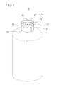
- FIG. 1 is a perspective view of a container having a ring-shaped carrier formed on a lid according to the present invention
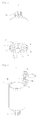
- FIG. 2 is a perspective view showing a state where a lid connecting member of the container is removed
- FIG. 3 is a perspective view showing a state where the ring-shaped carrier of the container is opened
- FIG. 4 is a perspective view showing a state where the ring-shaped carrier of the container is completely opened
- FIG. 5 is a perspective view of the container having the ring-shaped carrier formed on the bottom of the container according to the present invention
- FIG. 6 is a perspective view showing a state where the ring-shaped carrier formed on the bottom of the container is completely opened according to the present invention.
- the container (A) according to the present invention has a ring-shaped carrier 12 disposed on a side thereof.
- the container (A) includes a carrier joining part 21 disposed on a side for joining the ring-shaped carrier 12 thereto.
- the carrier joining part 21 and the ring-shaped carrier 12 may be disposed on a lid 10 of the container (A) as shown in FIGS. 1 to 4 , on the bottom of the container (A) as shown in FIGS. 5 and 6 , or on a side of the container (A) (not shown).
- the ring-shaped carrier 12 includes: a joining portion 13 formed on a side thereof and fixed to the carrier joining part 21; and a ring hole 14 formed on the inner circumferential surface of the ring-shaped carrier 12.
- a user can carry the container (A) while grasping the ring-shaped carrier 12 joined to the carrier joining portion 21 with the hand by means of the joining portion 13. Especially, a bar or a hook of furniture or clothes can be fit into the ring hole 14.
- the ring hole 14 is a ring-shaped through hole, and is formed by a support portion 15 and a hanging portion 17. That is, the support portion 15 and the hanging portion 17 are formed in a ring shape, and may be formed in a ring shape of various shapes, such as a triangular shape, a rectangular shape, a pentagonal shape, and so on, while they are formed in a circular ring in the drawings. Furthermore, the ring hole 14 formed inside the support portion 15 and the hanging portion 17 is in a circular form, but the outer appearances of the support portion 15 and the hanging portion 17 may adopt various shapes in horizontal section, such as a star shape, a triangular shape, a rectangular shape, a heart shape, and so on.
- the support portion 15 is constructed to be connected with the carrier joining part 21 by the joining portion 13, and the hanging portion 17 is constructed to be connected with the support portion 15 by a connection portion 16.
- a hanging slot 18 is formed between the support portion 15 and the hanging portion 17 in such a way that the user can fit a strap or a ring of the user's pocket or backpack into the hanging slot 18. Therefore, the user can easily hang the container having the ring-shaped carrier on the user's clothes or backpack through the hanging slot 18 and easily remove the container from the user's clothes or backpack when the user wants to use the container.
- the ring-shaped carrier 12 and the carrier joining part 21 of the container (A) according to the present invention can be formed on the bottom, a side, or the lid 10 of the top of the container (A).
- a lid connecting member 22 having a cut line is formed between the lid 10 and the ring-shaped carrier 12, and the lid connecting member 22 has a hand-grip portion 23 formed on a front end thereof.
- the carrier joining part 21 includes: a carrier joining area 24 to which the ring-shaped carrier 12 is joined; and an inner protrusion 25 extending from the body of the lid 10 and formed integrally with the lid 10.
- the inner protrusion 25 of the carrier joining part 21 is formed at the center of the top of the lid 10 and the carrier joining area 24 is formed outside relative to the inner protrusion 25 of the carrier joining part 21, such that the ring-shaped carrier 12 is joined and positioned onto the carrier joining area 24.
- the inner protrusion 25 disposed at the center of the carrier joining part 21 is provided to prevent movement of the ring-shaped carrier 12 after the ring-shaped carrier 12 is locked to the carrier joining part 21, and hence, the inner protrusion 25 of the carrier joining part 21 may be not formed if any external force is not applied.
- the attached drawings illustrate the example that the inner protrusion 25 is formed on the lid 10.
- the carrier connecting member 22 When the user grasps the hand-grip portion 23 of the carrier connecting member 22, which is disposed between the lid 10 and the ring-shaped carrier 12 for connecting the carrier 12 to the lid 10, with the hand and pulls it outward, as shown in FIG. 2 , the carrier connecting member 22 is removed from the lid 10. After that, when the carrier connecting member 22 is completely removed from the lid 10, as shown in FIG. 3 , the ring-shaped carrier 12 is in a state where it is removable from the carrier joining area 24 of the carrier joining part 21 formed on the lid 10.
- the ring-shaped carrier 12 is rotated upwardly based on the joining portion 13, which connects the ring-shaped carrier 12 and the carrier joining part 21 with each other.
- the hanging slot 18 formed between the support portion 15 and the hanging portion 17 is nearly in an erect state, and then, the user can insert a pocket jaw or a strap of the user's clothes or backpack into the hanging slot 18 to easily carry the container without dropping.
- the attached drawings illustrate the example that the carrier connecting member 22 is formed between the lid 10 and the ring-shaped carrier 12, but the carrier connecting member 22 may be not formed and a protrusion (not shown) may be formed on a side of the lid 10, such that the ring-shaped carrier 12 is normally hung on the protrusion of the lid 10 but is separated from the protrusion (not shown) when the user pulls the ring-shaped carrier 12 to use it.
- the ring-shaped carrier 12 includes: a retaining protrusion 19 formed at a portion of the outer circumference thereof; and a locking protrusion 26 formed on a portion of the inner circumference of the carrier joining part 21 in such a way as to meet with the retaining protrusion 19.
- the retaining protrusion 19 and the locking protrusion 26 may be formed integrally with each other and a cut line may be disposed between the retaining protrusion 19 and the locking protrusion 26 in such a way that the retaining protrusion 19 and the locking protrusion 26 are separated from each other while the cut line is broken when the user pulls the ring-shaped carrier 12.
- the ring-shaped carrier 12 when the user pulls the ring-shaped carrier 12, which is disposed on the carrier joining part 21, outwardly, the retaining protrusion 19 and the locking protrusion 26 are separated from each other, and then, as shown in FIG. 6 , the ring-shaped carrier 12 is rotated based on the joining portion 13 and stands upright at right angles to the initial state of the container (A).
- the user can insert a pocket jaw or a strap of the user's clothes or backpack into the hanging slot 18 formed between the support portion 15 and the hanging portion 17 of the ring-shaped carrier 12 to easily carry and use the container.
- the user can put a bar, a ring, or the user's finger into the ring hole 14, which is an inner space formed by the support portion 15 and the hanging portion 17, to carry the container (A), or the user can insert a hook of a shelf into the ring hole 14 to keep the container (A) in safety.
Landscapes
- Engineering & Computer Science (AREA)
- Mechanical Engineering (AREA)
- Details Of Rigid Or Semi-Rigid Containers (AREA)
- Closures For Containers (AREA)
- Purses, Travelling Bags, Baskets, Or Suitcases (AREA)
Abstract
Description
- The present invention relates to a container, and more particularly, to a container having a ring-shaped carrier, which is disposed on the bottom, a side, or a lid of the container to allow a user to easily grasp the container or easily put a strap of a pocket or a backpack into the ring-shaped carrier, thereby allowing the user to easily carry or keep the container in safety.
- In general, containers are to store contents therein and carry or keep the contents in safety for a certain period of time.
- Such a container includes an inner space for storing certain contents therein and an inlet for putting the contents in the container or discharging the contents from the container. Moreover, a lid is combined to the container to prevent that the contents contained in the container is discharged out.
- In order to put more contents in the container, the container must have certain volume, and hence, the container has a laterally expanded width. However, because the user cannot easily grasp such a container with the laterally expanded width, various designs of the container with the laterally expanded width, for instance, containers having a thin neck, have been attempted in order to allow the user to easily grasp the container. But, in spite of the above attempts for allowing the user to easily grasp the container, because the user grasps a part of the container with the hand, in the case of hot and cold contents, temperature of the contents may be changed by the user's temperature, and especially, the user's hand may be injured by the hot contents.
- Furthermore, the conventional container has another problem in that, in the case that the user has to grasp the container for a long time, the container can slip down from the user's hand because it is not easy to grasp the container for a long time even though the neck of the container is thin.
- Accordingly, the present invention has been made in an effort to solve the above-mentioned problems occurring in the prior arts, and it is an object of the present invention to provide a container having a ring-shaped carrier, which is disposed on the bottom, a side, or a lid of the container to allow a user to easily grasp the container or easily put a strap of a pocket or a backpack into the ring-shaped carrier, thereby allowing the user to easily carry or keep the container in safety.
- Another object of the present invention is to provide a container having a ring-shaped carrier, which is normally in close contact with a side of the lid or the container but is easily detached from the lid or the container when the user wants to use the ring-shaped carrier, thereby being easily kept in a box because the ring-shaped carrier does not initially dangle from the container.
- A further object of the present invention is not easily detached from the container if the user does not want to use it because the container has a lid connecting member, or a retaining protrusion, and a locking protrusion, thereby providing the container with a good appearance and providing the user with convenience in use.
- To achieve the above objects, the present invention provides a container, which has a ring-shaped carrier, including: a carrier joining part disposed to the ring-shaped carrier to the container, wherein the ring-shaped carrier includes: a joining portion formed on a side thereof and fixed to the carrier joining part; a ring hole formed on the inner circumferential surface of the ring-shaped carrier, the ring hole being a ring-shaped through hole; a support portion and a hanging portion constructed to form the ring hole, the support portion being connected with the carrier joining part by the joining portion, the hanging portion being connected with the support portion by a connection portion; and a hanging slot formed between the support portion and the hanging portion.
- Moreover, the carrier joining part and the ring-shaped carrier are formed on a lid, and a lid connecting member having a cut line is formed between the lid and the ring-shaped carrier and has a hand-grip portion formed on a front end thereof.
- Furthermore, the carrier joining part and the ring-shaped carrier are formed on a lid, and the carrier joining part includes: a carrier joining area to which the ring-shaped carrier is joined; and an inner protrusion extending from the body of the lid and formed integrally with the lid.
- Additionally, the carrier joining part and the ring-shaped carrier are formed on the bottom or a side of the container, and the ring-shaped carrier includes: a retaining protrusion formed at a portion of the outer circumference thereof; and a locking protrusion formed on a portion of the inner circumference of the carrier joining part in such a way as to meet with the retaining protrusion.
- As described above, the ring-shaped carrier, which is disposed on the bottom, the side, or the lid of the container, can allow the user to easily grasp the container or easily put a strap of a pocket or a backpack, so that the user can easily carry or keep the container in safety.
- Particularly, the ring-shaped carrier does not initially dangle from the container and can be easily kept in a box because it is normally in close contact with a side of the lid or the container but is easily detached from the lid or the container when the user wants to use the ring-shaped carrier.
- Moreover, the ring-shaped carrier is not easily detached from the container if the user does not want to use it because the container has the lid connecting member, or the retaining protrusion, and the locking protrusion, so that the ring-shaped carrier can provide the container with a good appearance and also provide the user with convenience in use.
-
-
FIG. 1 is a perspective view of a container having a ring-shaped carrier formed on a lid according to the present invention. -
FIG. 2 is a perspective view showing a state where a lid connecting member of the container is removed according to the present invention. -
FIG. 3 is a perspective view showing a state where the ring-shaped carrier of the container is opened according to the present invention. -
FIG. 4 is a perspective view showing a state where the ring-shaped carrier of the container is completely opened according to the present invention. -
FIG. 5 is a perspective view of the container having the ring-shaped carrier formed on the bottom of the container according to the present invention. -
FIG. 6 is a perspective view showing a state where the ring-shaped carrier formed on the bottom of the container is completely opened according to the present invention. -
A: container 10: lid 12: ring-shaped carrier 13: joining portion 14: ring hole 15: support portion 16: connection portion 17: hanging portion 18: hanging slot 19: retaining protrusion 21: carrier joining part 22: lid connecting member 24: carrier joining area 25: inner protrusion - Reference will be now made in detail to the preferred embodiment of the present invention with reference to the attached drawings.
-
FIG. 1 is a perspective view of a container having a ring-shaped carrier formed on a lid according to the present invention,FIG. 2 is a perspective view showing a state where a lid connecting member of the container is removed,FIG. 3 is a perspective view showing a state where the ring-shaped carrier of the container is opened,FIG. 4 is a perspective view showing a state where the ring-shaped carrier of the container is completely opened,FIG. 5 is a perspective view of the container having the ring-shaped carrier formed on the bottom of the container according to the present invention, andFIG. 6 is a perspective view showing a state where the ring-shaped carrier formed on the bottom of the container is completely opened according to the present invention. - As shown in
FIGS. 1 to 6 , the container (A) according to the present invention has a ring-shaped carrier 12 disposed on a side thereof. - The container (A) includes a
carrier joining part 21 disposed on a side for joining the ring-shaped carrier 12 thereto. Thecarrier joining part 21 and the ring-shaped carrier 12 may be disposed on alid 10 of the container (A) as shown inFIGS. 1 to 4 , on the bottom of the container (A) as shown inFIGS. 5 and 6 , or on a side of the container (A) (not shown). - The ring-
shaped carrier 12 includes: a joiningportion 13 formed on a side thereof and fixed to thecarrier joining part 21; and aring hole 14 formed on the inner circumferential surface of the ring-shaped carrier 12. - Therefore, a user can carry the container (A) while grasping the ring-
shaped carrier 12 joined to thecarrier joining portion 21 with the hand by means of the joiningportion 13. Especially, a bar or a hook of furniture or clothes can be fit into thering hole 14. - The
ring hole 14 is a ring-shaped through hole, and is formed by asupport portion 15 and a hangingportion 17. That is, thesupport portion 15 and thehanging portion 17 are formed in a ring shape, and may be formed in a ring shape of various shapes, such as a triangular shape, a rectangular shape, a pentagonal shape, and so on, while they are formed in a circular ring in the drawings. Furthermore, thering hole 14 formed inside thesupport portion 15 and the hangingportion 17 is in a circular form, but the outer appearances of thesupport portion 15 and the hangingportion 17 may adopt various shapes in horizontal section, such as a star shape, a triangular shape, a rectangular shape, a heart shape, and so on. - Additionally, the
support portion 15 is constructed to be connected with thecarrier joining part 21 by the joiningportion 13, and thehanging portion 17 is constructed to be connected with thesupport portion 15 by aconnection portion 16. - Moreover, a
hanging slot 18 is formed between thesupport portion 15 and the hangingportion 17 in such a way that the user can fit a strap or a ring of the user's pocket or backpack into thehanging slot 18. Therefore, the user can easily hang the container having the ring-shaped carrier on the user's clothes or backpack through thehanging slot 18 and easily remove the container from the user's clothes or backpack when the user wants to use the container. - The ring-
shaped carrier 12 and thecarrier joining part 21 of the container (A) according to the present invention can be formed on the bottom, a side, or thelid 10 of the top of the container (A). - First, as shown in
FIGS. 1 to 4 , an example that the ring-shaped carrier 12 and thecarrier joining part 21 of the container (A) are formed on thelid 10 disposed on the top of the container (A) will be described. - A
lid connecting member 22 having a cut line is formed between thelid 10 and the ring-shaped carrier 12, and thelid connecting member 22 has a hand-grip portion 23 formed on a front end thereof. - Furthermore, the
carrier joining part 21 includes: acarrier joining area 24 to which the ring-shaped carrier 12 is joined; and aninner protrusion 25 extending from the body of thelid 10 and formed integrally with thelid 10. - As described above, in the case that the ring-
shaped carrier 12 and thecarrier joining part 21 are formed on thelid 10 of the container (A), the process of using the ring-shaped carrier and the container will be described as follows. - The
inner protrusion 25 of thecarrier joining part 21 is formed at the center of the top of thelid 10 and thecarrier joining area 24 is formed outside relative to theinner protrusion 25 of thecarrier joining part 21, such that the ring-shaped carrier 12 is joined and positioned onto thecarrier joining area 24. Of course, theinner protrusion 25 disposed at the center of thecarrier joining part 21 is provided to prevent movement of the ring-shaped carrier 12 after the ring-shaped carrier 12 is locked to thecarrier joining part 21, and hence, theinner protrusion 25 of thecarrier joining part 21 may be not formed if any external force is not applied. However, the attached drawings illustrate the example that theinner protrusion 25 is formed on thelid 10. - When the user grasps the hand-
grip portion 23 of thecarrier connecting member 22, which is disposed between thelid 10 and the ring-shaped carrier 12 for connecting thecarrier 12 to thelid 10, with the hand and pulls it outward, as shown inFIG. 2 , thecarrier connecting member 22 is removed from thelid 10. After that, when thecarrier connecting member 22 is completely removed from thelid 10, as shown inFIG. 3 , the ring-shaped carrier 12 is in a state where it is removable from thecarrier joining area 24 of thecarrier joining part 21 formed on thelid 10. - Accordingly, when the user grasps and pulls the
support portion 15 and the hangingportion 17 or thering hole 14 of the ring-shaped carrier 12, the ring-shaped carrier 12 is rotated upwardly based on the joiningportion 13, which connects the ring-shaped carrier 12 and thecarrier joining part 21 with each other. - After that, when the user rotates the ring-
shaped carrier 12 more, thehanging slot 18 formed between thesupport portion 15 and the hangingportion 17 is nearly in an erect state, and then, the user can insert a pocket jaw or a strap of the user's clothes or backpack into the hangingslot 18 to easily carry the container without dropping. - The attached drawings illustrate the example that the
carrier connecting member 22 is formed between thelid 10 and the ring-shaped carrier 12, but thecarrier connecting member 22 may be not formed and a protrusion (not shown) may be formed on a side of thelid 10, such that the ring-shaped carrier 12 is normally hung on the protrusion of thelid 10 but is separated from the protrusion (not shown) when the user pulls the ring-shaped carrier 12 to use it. - Next, an example that the ring-
shaped carrier 12 and thecarrier joining part 21 of the container (A) are formed on the bottom of the container (A) will be described. - As shown in
FIGS. 5 and 6 , the ring-shaped carrier 12 includes: aretaining protrusion 19 formed at a portion of the outer circumference thereof; and alocking protrusion 26 formed on a portion of the inner circumference of thecarrier joining part 21 in such a way as to meet with theretaining protrusion 19. Not shown in the drawings, theretaining protrusion 19 and thelocking protrusion 26 may be formed integrally with each other and a cut line may be disposed between theretaining protrusion 19 and thelocking protrusion 26 in such a way that the retainingprotrusion 19 and thelocking protrusion 26 are separated from each other while the cut line is broken when the user pulls the ring-shaped carrier 12. - That is, when the user pulls the ring-
shaped carrier 12, which is disposed on thecarrier joining part 21, outwardly, theretaining protrusion 19 and thelocking protrusion 26 are separated from each other, and then, as shown inFIG. 6 , the ring-shaped carrier 12 is rotated based on the joiningportion 13 and stands upright at right angles to the initial state of the container (A). - Therefore, the user can insert a pocket jaw or a strap of the user's clothes or backpack into the hanging
slot 18 formed between thesupport portion 15 and the hangingportion 17 of the ring-shaped carrier 12 to easily carry and use the container. - Of course, because the
support portion 15 and the hangingportion 17 of the ring-shapedcarrier 12 are formed in the ring shape, the user can put a bar, a ring, or the user's finger into thering hole 14, which is an inner space formed by thesupport portion 15 and the hangingportion 17, to carry the container (A), or the user can insert a hook of a shelf into thering hole 14 to keep the container (A) in safety. - While the present invention has been described with reference to the particular illustrative embodiment, it is not to be restricted by the above embodiment but only by the appended claims. It is to be appreciated that those skilled in the art can change or modify the embodiment without departing from the scope and spirit of the present invention described in the claims.
Claims (5)
- A container having a ring-shaped carrier, wherein the container comprises:a carrier joining part (21) disposed to the ring-shaped carrier (12) to the container (A), andwherein the ring-shaped carrier (12) comprises:a joining portion (13) formed on a side thereof and fixed to the carrier joining part (21);a ring hole (14) formed on the inner circumferential surface of the ring-shaped carrier (12), the ring hole (14) being a ring-shaped through hole;a support portion (15) and a hanging portion (17) constructed to form the ring hole (14), the support portion being connected with the carrier joining part (21) by the joining portion (13), the hanging portion (17) being connected with the support portion (15) by a connection portion (16); anda hanging slot (18) formed between the support portion (15) and the hanging portion (17).
- (Deleted)
- The container having the ring-shaped carrier according to claim 1, wherein the carrier joining part (21) and the ring-shaped carrier (12) are formed on a lid (10), and a lid connecting member (22) having a cut line is formed between the lid (10) and the ring-shaped carrier (12) and has a hand-grip portion (23) formed on a front end thereof.
- The container having the ring-shaped carrier according to claim 1, wherein the carrier joining part (21) and the ring-shaped carrier (12) are formed on a lid (10), and the carrier joining part (21) comprises: a carrier joining area (24) to which the ring-shaped carrier (12) is joined; and an inner protrusion (25) extending from the body of the lid (10) and formed integrally with the lid (10).
- The container having the ring-shaped carrier according to claim 1, wherein the carrier joining part (21) and the ring-shaped carrier (12) are formed on the bottom or a side of the container (A), and the ring-shaped carrier (12) comprises: a retaining protrusion (19) formed at a portion of the outer circumference thereof; and a locking protrusion (26) formed on a portion of the inner circumference of the carrier joining part (21) in such a way as to meet with the retaining protrusion (19).
Applications Claiming Priority (2)
| Application Number | Priority Date | Filing Date | Title |
|---|---|---|---|
| KR1020080084361A KR100998249B1 (en) | 2008-08-28 | 2008-08-28 | Battle with ring-carrier of ring-hook type |
| PCT/KR2009/004551 WO2010024544A2 (en) | 2008-08-28 | 2009-08-14 | Container with ring carrier for hanging ring |
Publications (2)
| Publication Number | Publication Date |
|---|---|
| EP2322444A2 true EP2322444A2 (en) | 2011-05-18 |
| EP2322444A4 EP2322444A4 (en) | 2011-12-14 |
Family
ID=41722072
Family Applications (1)
| Application Number | Title | Priority Date | Filing Date |
|---|---|---|---|
| EP09810149A Withdrawn EP2322444A4 (en) | 2008-08-28 | 2009-08-14 | Container with ring carrier for hanging ring |
Country Status (6)
| Country | Link |
|---|---|
| US (1) | US20110147396A1 (en) |
| EP (1) | EP2322444A4 (en) |
| JP (1) | JP2012500760A (en) |
| KR (1) | KR100998249B1 (en) |
| CN (1) | CN102202983A (en) |
| WO (1) | WO2010024544A2 (en) |
Families Citing this family (1)
| Publication number | Priority date | Publication date | Assignee | Title |
|---|---|---|---|---|
| JP1608426S (en) * | 2017-07-24 | 2018-07-09 |
Citations (4)
| Publication number | Priority date | Publication date | Assignee | Title |
|---|---|---|---|---|
| DE3443546A1 (en) * | 1984-11-29 | 1986-06-05 | Wella Ag, 6100 Darmstadt | Suspension device |
| US20040129702A1 (en) * | 2002-10-15 | 2004-07-08 | Jensen Simon Hem | Handle for containers |
| US6766917B1 (en) * | 2002-09-11 | 2004-07-27 | Blewitt, Iii John J. | Closure with hinged hook |
| US20080142531A1 (en) * | 2004-06-25 | 2008-06-19 | Simon Hem Jensen | Container Body with an Integrated Handle |
Family Cites Families (19)
| Publication number | Priority date | Publication date | Assignee | Title |
|---|---|---|---|---|
| CA848786A (en) * | 1968-03-23 | 1970-08-11 | Tamper-Proof-Tops Industries Ltd. | Container closure |
| US3744658A (en) * | 1971-12-13 | 1973-07-10 | M Fujio | Dripping bottle |
| US3866782A (en) * | 1973-12-10 | 1975-02-18 | Continental Can Co | Composite closure |
| JPS6232042Y2 (en) * | 1981-04-03 | 1987-08-17 | ||
| US4460143A (en) * | 1981-04-23 | 1984-07-17 | Fujisawa Pharmaceutical Co., Ltd. | Vial suspender |
| JPS59121333U (en) * | 1983-02-03 | 1984-08-15 | 東洋製罐株式会社 | Vending machine stock solution supply device |
| JPS6030203Y2 (en) * | 1983-12-29 | 1985-09-11 | 東罐興業株式会社 | Lid for easy inversion |
| US4582215A (en) * | 1985-01-11 | 1986-04-15 | The Coca-Cola Company | Container carrier |
| US4712671A (en) * | 1986-05-27 | 1987-12-15 | Salacuse Frank S | Universal hanging packaging system |
| JPS63164442U (en) * | 1987-04-16 | 1988-10-26 | ||
| US6065649A (en) * | 1997-10-23 | 2000-05-23 | Scoggins; Lester E. | Dispensing container with top and bottom access ports and a dispensing manifold therefore |
| JP2001039444A (en) * | 1999-07-29 | 2001-02-13 | Aoki Technical Laboratory Inc | Plastic bottle with handle at its neck |
| JP2002160738A (en) * | 2000-11-24 | 2002-06-04 | Haatsutekku Saitama:Kk | Plastic container with handle member |
| SI20739A (en) * | 2000-11-28 | 2002-06-30 | G.Loc, Trgovina In Storitve D.O.O. | A cap of a container, especially bottle or plastic bottle |
| US20020084241A1 (en) * | 2000-12-28 | 2002-07-04 | Lin Yu-Hsien | Plastic bottle neck ring with a pull-up ring |
| US6880714B2 (en) * | 2002-09-18 | 2005-04-19 | Tom Blanchester | Carrying device for a bottle |
| KR200365978Y1 (en) * | 2004-08-09 | 2004-10-28 | 옥준석 | spout cap for can |
| US7799008B2 (en) * | 2006-03-09 | 2010-09-21 | William Hendricks | Bottle for delivering nutrients to an enteral feeding tube |
| US20080099424A1 (en) * | 2006-10-30 | 2008-05-01 | Adam Chalekian | Apparatus and methods for carrying a bottle |
-
2008
- 2008-08-28 KR KR1020080084361A patent/KR100998249B1/en active IP Right Grant
-
2009
- 2009-08-14 CN CN2009801340192A patent/CN102202983A/en active Pending
- 2009-08-14 EP EP09810149A patent/EP2322444A4/en not_active Withdrawn
- 2009-08-14 JP JP2011524889A patent/JP2012500760A/en active Pending
- 2009-08-14 WO PCT/KR2009/004551 patent/WO2010024544A2/en active Application Filing
- 2009-08-14 US US13/061,397 patent/US20110147396A1/en not_active Abandoned
Patent Citations (4)
| Publication number | Priority date | Publication date | Assignee | Title |
|---|---|---|---|---|
| DE3443546A1 (en) * | 1984-11-29 | 1986-06-05 | Wella Ag, 6100 Darmstadt | Suspension device |
| US6766917B1 (en) * | 2002-09-11 | 2004-07-27 | Blewitt, Iii John J. | Closure with hinged hook |
| US20040129702A1 (en) * | 2002-10-15 | 2004-07-08 | Jensen Simon Hem | Handle for containers |
| US20080142531A1 (en) * | 2004-06-25 | 2008-06-19 | Simon Hem Jensen | Container Body with an Integrated Handle |
Non-Patent Citations (1)
| Title |
|---|
| See also references of WO2010024544A2 * |
Also Published As
| Publication number | Publication date |
|---|---|
| WO2010024544A3 (en) | 2010-06-24 |
| JP2012500760A (en) | 2012-01-12 |
| KR100998249B1 (en) | 2010-12-03 |
| EP2322444A4 (en) | 2011-12-14 |
| US20110147396A1 (en) | 2011-06-23 |
| KR20100025703A (en) | 2010-03-10 |
| CN102202983A (en) | 2011-09-28 |
| WO2010024544A2 (en) | 2010-03-04 |
Similar Documents
| Publication | Publication Date | Title |
|---|---|---|
| US10689157B2 (en) | Food and beverage cooler assembly | |
| US7140507B2 (en) | Insulated ice chest with accessory holders | |
| US8695794B2 (en) | Electronic cigarette container and method therefor | |
| US11591136B2 (en) | Bottle with detachable housing and corresponding storage compartment | |
| EP1340686B1 (en) | Tubular-shape storage case | |
| WO2006009537A1 (en) | Insulated ice chest with accessory holders | |
| US20130334237A1 (en) | Beverage insulator and opener | |
| US20060213907A1 (en) | Cup and lid combination | |
| US3650381A (en) | Display rack | |
| EP2322444A2 (en) | Container with ring carrier for hanging ring | |
| JP2001074359A5 (en) | ||
| JP2009067411A (en) | Vessel with small article-accommodating part | |
| JP4359886B2 (en) | Detachable lid device | |
| JP2017074949A (en) | Heat/cold insulation bag | |
| KR200493525Y1 (en) | warm and cool-keeping bag for golf cart and bag set having this same | |
| EP4039128B1 (en) | Beverage container with hanging member | |
| CN208892181U (en) | A kind of coffee cup suit | |
| KR200342168Y1 (en) | Powdered milk case that storage of spoon is easy | |
| CN209499378U (en) | A kind of vacuum cup and its pedestal | |
| US11136181B2 (en) | Popcorn container | |
| JP3375385B2 (en) | Separable holding resin container | |
| CN209750649U (en) | Cup structure | |
| JP2741503B2 (en) | Cup | |
| JPS601053Y2 (en) | container holder | |
| JP2002308340A (en) | Cooler box |
Legal Events
| Date | Code | Title | Description |
|---|---|---|---|
| PUAI | Public reference made under article 153(3) epc to a published international application that has entered the european phase |
Free format text: ORIGINAL CODE: 0009012 |
|
| 17P | Request for examination filed |
Effective date: 20110328 |
|
| AK | Designated contracting states |
Kind code of ref document: A2 Designated state(s): AT BE BG CH CY CZ DE DK EE ES FI FR GB GR HR HU IE IS IT LI LT LU LV MC MK MT NL NO PL PT RO SE SI SK SM TR |
|
| AX | Request for extension of the european patent |
Extension state: AL BA RS |
|
| DAX | Request for extension of the european patent (deleted) | ||
| A4 | Supplementary search report drawn up and despatched |
Effective date: 20111114 |
|
| RIC1 | Information provided on ipc code assigned before grant |
Ipc: B65D 23/00 20060101ALI20111108BHEP Ipc: B65D 25/22 20060101AFI20111108BHEP |
|
| STAA | Information on the status of an ep patent application or granted ep patent |
Free format text: STATUS: THE APPLICATION IS DEEMED TO BE WITHDRAWN |
|
| 18D | Application deemed to be withdrawn |
Effective date: 20120612 |