EP2322361A1 - Run-flat support for motor vehicle and mounted assembly comprising same - Google Patents
Run-flat support for motor vehicle and mounted assembly comprising same Download PDFInfo
- Publication number
- EP2322361A1 EP2322361A1 EP10189676A EP10189676A EP2322361A1 EP 2322361 A1 EP2322361 A1 EP 2322361A1 EP 10189676 A EP10189676 A EP 10189676A EP 10189676 A EP10189676 A EP 10189676A EP 2322361 A1 EP2322361 A1 EP 2322361A1
- Authority
- EP
- European Patent Office
- Prior art keywords
- sector
- sectors
- flat
- axes
- articulated
- Prior art date
- Legal status (The legal status is an assumption and is not a legal conclusion. Google has not performed a legal analysis and makes no representation as to the accuracy of the status listed.)
- Granted
Links
- 238000005096 rolling process Methods 0.000 claims description 16
- 229920001971 elastomer Polymers 0.000 claims description 11
- 239000011253 protective coating Substances 0.000 claims description 7
- 239000002131 composite material Substances 0.000 claims description 6
- 230000000903 blocking effect Effects 0.000 claims description 5
- 230000002441 reversible effect Effects 0.000 claims description 5
- 239000011324 bead Substances 0.000 claims description 4
- 238000006073 displacement reaction Methods 0.000 claims description 4
- 239000002184 metal Substances 0.000 claims description 4
- 230000003014 reinforcing effect Effects 0.000 claims description 4
- 230000000694 effects Effects 0.000 claims description 3
- 239000004033 plastic Substances 0.000 claims description 3
- 239000004753 textile Substances 0.000 claims description 3
- 125000006850 spacer group Chemical group 0.000 claims 1
- 241000422252 Cales Species 0.000 description 4
- 239000011248 coating agent Substances 0.000 description 3
- 238000000576 coating method Methods 0.000 description 3
- 230000036961 partial effect Effects 0.000 description 3
- 230000002787 reinforcement Effects 0.000 description 3
- 239000004952 Polyamide Substances 0.000 description 2
- 230000006835 compression Effects 0.000 description 2
- 238000007906 compression Methods 0.000 description 2
- 238000003780 insertion Methods 0.000 description 2
- 230000037431 insertion Effects 0.000 description 2
- 239000011159 matrix material Substances 0.000 description 2
- 239000002689 soil Substances 0.000 description 2
- 239000007787 solid Substances 0.000 description 2
- 229920000049 Carbon (fiber) Polymers 0.000 description 1
- 101100536354 Drosophila melanogaster tant gene Proteins 0.000 description 1
- RRHGJUQNOFWUDK-UHFFFAOYSA-N Isoprene Chemical compound CC(=C)C=C RRHGJUQNOFWUDK-UHFFFAOYSA-N 0.000 description 1
- 241000826860 Trapezium Species 0.000 description 1
- 239000004917 carbon fiber Substances 0.000 description 1
- 239000003822 epoxy resin Substances 0.000 description 1
- 239000011152 fibreglass Substances 0.000 description 1
- 239000003365 glass fiber Substances 0.000 description 1
- 230000000670 limiting effect Effects 0.000 description 1
- 238000000034 method Methods 0.000 description 1
- 238000007747 plating Methods 0.000 description 1
- 229920002647 polyamide Polymers 0.000 description 1
- 229920006122 polyamide resin Polymers 0.000 description 1
- 229920000647 polyepoxide Polymers 0.000 description 1
- 229920001195 polyisoprene Polymers 0.000 description 1
- 230000002829 reductive effect Effects 0.000 description 1
- 230000035939 shock Effects 0.000 description 1
Images


Classifications
-
- B—PERFORMING OPERATIONS; TRANSPORTING
- B60—VEHICLES IN GENERAL
- B60C—VEHICLE TYRES; TYRE INFLATION; TYRE CHANGING; CONNECTING VALVES TO INFLATABLE ELASTIC BODIES IN GENERAL; DEVICES OR ARRANGEMENTS RELATED TO TYRES
- B60C17/00—Tyres characterised by means enabling restricted operation in damaged or deflated condition; Accessories therefor
- B60C17/04—Tyres characterised by means enabling restricted operation in damaged or deflated condition; Accessories therefor utilising additional non-inflatable supports which become load-supporting in emergency
- B60C17/06—Tyres characterised by means enabling restricted operation in damaged or deflated condition; Accessories therefor utilising additional non-inflatable supports which become load-supporting in emergency resilient
-
- B—PERFORMING OPERATIONS; TRANSPORTING
- B60—VEHICLES IN GENERAL
- B60C—VEHICLE TYRES; TYRE INFLATION; TYRE CHANGING; CONNECTING VALVES TO INFLATABLE ELASTIC BODIES IN GENERAL; DEVICES OR ARRANGEMENTS RELATED TO TYRES
- B60C17/00—Tyres characterised by means enabling restricted operation in damaged or deflated condition; Accessories therefor
- B60C17/04—Tyres characterised by means enabling restricted operation in damaged or deflated condition; Accessories therefor utilising additional non-inflatable supports which become load-supporting in emergency
- B60C17/041—Tyres characterised by means enabling restricted operation in damaged or deflated condition; Accessories therefor utilising additional non-inflatable supports which become load-supporting in emergency characterised by coupling or locking means between rim and support
Definitions
- the document EP-A-1,588,870 has an annular articular ring support structure articulated specifically for a circumferential groove monoblock wheel rim, the structure being usable without heel locking means against the rim flanges.
- Each articulation between sectors consists of at least two links articulated one over the other thus forming a complex deformable articulation with the two orifices of the joint in which are mounted the two transverse axes which belong respectively to the two links and not to one and the same rigid tab, which has the particular disadvantage of complicating the joints.
- one of the ends of each sector, or male end may advantageously terminate in a male interlocking member which projects in the circumferential direction radially above said articulation and which is able to fit partially into a female end of the adjacent sector.
- each sector may be recessed on a substantially median portion of their axial width so as to form, at each sector end, a recess which extends over at least a portion of the length of the sector in the circumferential direction and which is delimited axially by two axial recess faces both traversed by said axis fixed at this sector end.
Abstract
Description
La présente invention concerne un dispositif de roulage à plat destiné à équiper un ensemble monté sans chambre à air pour véhicule automobile et un tel ensemble monté incorporant ce dispositif, permettant de parcourir une distance importante à vitesse relativement élevée lorsque l'ensemble monté est partiellement ou totalement dégonflé. Ce dispositif de roulage à plat est notamment utilisable pour équiper un véhicule militaire destiné à évoluer sur tous types de sols incluant des sols sablonneux.The present invention relates to a flat rolling device intended to equip a set mounted without a tube for a motor vehicle and such a mounted assembly incorporating this device, making it possible to travel a considerable distance at a relatively high speed when the assembled assembly is partially or totally deflated. This flat running device is particularly usable for equipping a military vehicle intended to evolve on all types of soils including sandy soils.
Les dispositifs de roulage à plat connus sont généralement constitués par un anneau de soutien monté avec jeu autour d'une jante de roue à l'intérieur d'une enveloppe de pneumatique. Cet anneau exerce du fait de sa largeur à sa base un effort de plaquage de l'enveloppe sur la jante. On utilise parfois des dispositifs rigides en plusieurs secteurs qui sont fixés deux à deux. Ainsi, le document
Le document
Un inconvénient majeur de ce dernier dispositif de roulage à plat à secteurs articulés par des charnières réside notamment dans le caractère rigide de ces articulations du fait de l'emboîtement et de la charnière précités.A major disadvantage of the latter device for flat rolling hinged sectors resides in particular in the rigid nature of these joints due to the aforementioned interlocking and hinge.
Le document
Un but de la présente invention est de proposer un dispositif de roulage à plat destiné à équiper un ensemble monté sans chambre à air pour véhicule automobile qui comporte une jante de roue à plusieurs parties et une enveloppe de pneumatique comportant des talons montés contre des rebords de ladite jante, ledit dispositif comprenant :
- une structure annulaire de soutien destinée à être montée autour de la jante en vue de soutenir l'enveloppe, suite à une chute de pression de gonflage dans l'ensemble monté, et qui est divisée en au moins deux secteurs d'anneau en arc de cercle adaptés pour former la structure par juxtaposition dans la direction circonférentielle, ces secteurs étant deux à deux articulés entre eux dans cette direction par des moyens de connexion, et
- des moyens de blocage des talons contre ces rebords qui sont destinés à relier ladite structure annulaire de soutien à ces talons,
- an annular supporting structure to be mounted around the rim to support the casing, following an inflation pressure drop in the mounted assembly, and which is divided into at least two arcuate ring sectors of circle adapted to form the structure by juxtaposition in the circumferential direction, these sectors being two to two articulated together in this direction by means of connection, and
- heel locking means against these flanges which are intended to connect said annular supporting structure to these beads,
A cet effet, un dispositif selon l'invention est tel que lesdits moyens de connexion sont localisés entre les deux faces latérales de chacun des deux secteurs qu'ils articulent entre eux, et comportent deux axes s'étendant dans la direction axiale du dispositif qui sont respectivement fixés dans deux extrémités de connexion en regard de ces secteurs et qui sont reliés entre eux par une articulation s'étendant dans la direction circonférentielle du dispositif, ladite articulation étant constituée par au moins une patte rigide à deux orifices traversants ou bien par au moins un lien flexible à deux boucles, ladite au moins une patte ou ledit au moins un lien étant articulé sur ces axes par ces deux orifices ou boucles, respectivement.For this purpose, a device according to the invention is such that said connecting means are located between the two lateral faces of each of the two sectors that they articulate with each other, and comprise two axes. extending in the axial direction of the device which are respectively fixed in two connection ends facing these sectors and which are interconnected by a hinge extending in the circumferential direction of the device, said hinge being constituted by at least one rigid lug with two through holes or by at least one flexible link with two loops, said at least one lug or said at least one link being articulated on these axes by these two orifices or loops, respectively.
Par « axes », on entend ici de manière connue des pivots sur lesquels, selon la présente invention, vient s'articuler ladite articulation à la manière d'un joint mobile, ce qui confère la flexibilité recherchée au dispositif selon l'invention.By "axes" is meant here in a known manner pivots on which, according to the present invention, articulates said articulation in the manner of a movable joint, which gives the desired flexibility to the device according to the invention.
Pour chaque articulation, on notera que la ou chaque patte ou bien que le ou chaque lien flexible, selon le cas, est articulé(e) à lui(elle) seul(e) sur ces deux axes, contrairement à chaque articulation complexe du document
Selon une autre caractéristique de l'invention, lesdits moyens de blocage peuvent avantageusement comporter une paire de cales annulaires monoblocs qui sont appliquées axialement de part et d'autre de ladite structure de soutien et en regard d'une zone radialement intérieure de cette structure où sont montés lesdits axes, de sorte à positionner et à immobiliser ces derniers à l'intérieur des secteurs correspondants par le blocage latéral de ces axes à la hauteur radiale déterminée par ces cales.According to another characteristic of the invention, said locking means may advantageously comprise a pair of monobloc annular shims which are applied axially on either side of said support structure and opposite a radially inner zone of this structure where are mounted said axes, so as to position and immobilize them within the corresponding sectors by the lateral locking of these axes at the radial height determined by these wedges.
Chacune de ces deux cales peut présenter une section axiale sensiblement en forme de trapèze dont les petite et grande bases définissent respectivement des faces radialement intérieure et extérieure desdits moyens de blocage, chaque cale étant de préférence à base de caoutchouc renforcé par un élément de renforcement circonférentiel,Each of these two shims may have a substantially trapezoidal axial section whose small and large bases respectively define radially inner and outer faces of said locking means, each shim preferably being based on rubber reinforced by a circumferential reinforcing element ,
Selon une autre caractéristique de l'invention, lesdits axes peuvent être formés de deux axes par exemple à épaulement qui sont respectivement montés dans lesdits deux orifices traversants ou boucles de ladite articulation et qui sont fixés à l'intérieur des deux secteurs articulés correspondants.According to another characteristic of the invention, said axes may be formed of two axes, for example at shoulder, which are respectively mounted in said two through-holes or loops of said articulation and which are fixed inside the two corresponding articulated sectors.
Selon un exemple de réalisation de l'invention, l'une des extrémités de chaque secteur, ou extrémité mâle, peut avantageusement se terminer par un organe mâle d'emboîtement qui fait saillie dans la direction circonférentielle radialement au-dessus de ladite articulation et qui est apte à s'emboîter partiellement dans une extrémité femelle du secteur adjacent.According to an exemplary embodiment of the invention, one of the ends of each sector, or male end, may advantageously terminate in a male interlocking member which projects in the circumferential direction radially above said articulation and which is able to fit partially into a female end of the adjacent sector.
En variante, les secteurs articulés peuvent être aptes à se déplacer réversiblement l'un par rapport à l'autre dans la direction axiale et en torsion autour de la direction circonférentielle via lesdits moyens de blocage, sous l'effet d'efforts latéraux de cisaillement ou de compression appliqués à l'enveloppe en roulage à plat ou à l'état gonflé. Ce dispositif selon l'invention peut ainsi absorber les chocs en roulage à plat et à l'état gonflé à basse pression par des ajustements réversibles tant axiaux qu'en torsion, via la déformabilité de ces moyens de connexion.As a variant, the articulated sectors may be able to move reversibly relative to each other in the axial direction and in torsion around the circumferential direction via the said locking means, under the effect of lateral shear forces. or compression applied to the casing running flat or inflated. This device according to the invention can thus absorb shocks run flat and in the inflated state at low pressure by reversible adjustments both axial and torsion, via the deformability of these connection means.
L'articulation selon cette variante est alors par exemple de type rigide et est constituée de ladite au moins une patte ou goupille (par exemple métallique ou plastique) articulée sur ces axes qui est apte à coulisser axialement et à pivoter sur ces derniers de sorte à permettre ce déplacement réversible des secteurs ainsi articulés. En variante, cette articulation peut être de type déformable et être constituée dudit au moins un lien flexible articulé via lesdites deux boucles sur ces axes, tel qu'au moins un câblé textile et/ou un câble métallique, ce lien étant apte à se déplacer sur ces axes de sorte à permettre ce déplacement réversible des secteurs.The hinge according to this variant is then for example of rigid type and is constituted of said at least one lug or pin (for example metal or plastic) articulated on these axes which is able to slide axially and to pivot on the latter so as to allow this reversible displacement of the sectors thus articulated. As a variant, this articulation may be of the deformable type and be constituted by said at least one articulated flexible link via said two loops on these axes, such as at least one textile cord and / or a metal cable, this link being able to move on these axes so as to allow this reversible displacement of the sectors.
Selon une autre caractéristique de l'invention, les deux extrémités de chaque secteur peuvent être évidées sur une partie sensiblement médiane de leur largeur axiale de sorte à former, en chaque extrémité de secteur, un évidement qui s'étend sur au moins une partie de la longueur du secteur dans la direction circonférentielle et qui est délimité axialement par deux faces axiales d'évidement traversées toutes deux par ledit axe fixé à cette extrémité de secteur.According to another characteristic of the invention, the two ends of each sector may be recessed on a substantially median portion of their axial width so as to form, at each sector end, a recess which extends over at least a portion of the length of the sector in the circumferential direction and which is delimited axially by two axial recess faces both traversed by said axis fixed at this sector end.
Avantageusement, chaque axe peut traverser axialement de part en part le secteur l'incorporant, via un logement axial traversant qui est formé entre chaque face axiale d'évidement et la face latérale en regard de ce secteur et qui reçoit cet axe.Advantageously, each axis can pass axially right through the sector incorporating it, via a through axial housing which is formed between each axial recess face and the lateral face opposite this sector and which receives this axis.
Selon une autre caractéristique de l'invention, lesdits deux évidements que présentent respectivement les deux extrémités de connexion de chaque secteur peuvent s'étendre radialement à partir de la face radialement interne de ce secteur, chaque évidement présentant une section axiale sensiblement rectangulaire.According to another characteristic of the invention, said two recesses that respectively present the two connection ends of each sector may extend radially from the radially inner face of this sector, each recess having a substantially rectangular axial section.
Selon un premier mode de réalisation de l'invention, lesdits deux évidements de chaque secteur s'étendent jusqu'à la face radialement externe de ce secteur, étant ainsi traversants dans la direction radiale de ce dernier.According to a first embodiment of the invention, said two recesses of each sector extend to the radially outer face of this sector, thus being through in the radial direction of the latter.
Selon un second mode de réalisation de l'invention, lesdits deux évidements de chaque secteur se terminent radialement à distance de la face radialement externe de ce secteur, étant ainsi borgnes dans la direction radiale de ce dernier, chaque secteur étant optionnellement surmonté d'un revêtement de protection à base de caoutchouc. Ce revêtement de protection peut avantageusement être constitué d'un caoutchouc rigide, ou bien d'un composite caoutchouc souple / éléments de renforcement.According to a second embodiment of the invention, said two recesses of each sector terminate radially away from the radially outer face of this sector, thus being blind in the radial direction of the latter, each sector being optionally surmounted by a protective coating based on rubber. This protective coating may advantageously consist of a rigid rubber, or a flexible rubber composite / reinforcing elements.
On notera que cette portion de protection en caoutchouc permet non seulement de protéger la face radialement externe de la structure annulaire de soutien, mais en outre de protéger l'enveloppe de pneumatique en roulage à l'état gonflé lors d'un choc par exemple, en cas de contact du dispositif avec les flancs ou le sommet de l'enveloppe.It will be noted that this rubber protection portion not only makes it possible to protect the radially outer face of the annular supporting structure, but also to protect the tire casing when rolling in the inflated state during an impact, for example, in case of contact of the device with the sidewalls or the top of the envelope.
Selon une autre caractéristique de l'invention commune à ces deux modes de réalisation, chacun desdits secteurs peut indifféremment présenter une structure pleine, creuse ou ajourée (par exemple ajourée au niveau de sa face radialement interne et/ou de ses faces latérales), et il est de préférence réalisé en un matériau plastique ou composite. A titre encore plus préférentiel, on utilise un matériau composite pouvant comprendre une matrice polymérique (par exemple en polyamide ou en résine époxyde) renforcée par une armature de fibres de verre ou de carbone.According to another characteristic of the invention common to these two embodiments, each of said sectors may indifferently have a solid, hollow or perforated structure (for example perforated at its radially internal face and / or its lateral faces), and it is preferably made of a plastic or composite material. Even more preferably, a composite material may be used which may comprise a polymeric matrix (for example made of polyamide or epoxy resin) reinforced by a reinforcement of glass or carbon fibers.
Un ensemble monté sans chambre à air selon l'invention pour véhicule automobile, comprend une jante de roue à plusieurs parties, une enveloppe de pneumatique comportant des talons respectivement montés contre des rebords axialement interne et externe de la jante, et un dispositif de roulage à plat monté autour de la jante entre lesdits rebords, et cet ensemble monté est caractérisé en ce que le dispositif est tel que défini ci-dessus.An assembly mounted without a tube according to the invention for a motor vehicle, comprises a multi-part wheel rim, a tire casing comprising heels respectively mounted against the axially inner and outer rims of the rim, and a rolling device. flat mounted around the rim between said flanges, and this mounted assembly is characterized in that the device is as defined above.
Avantageusement, ladite jante est de type à deux parties boulonnées et peut présenter un fond de jante sensiblement plat (i.e. sans creux de jante).Advantageously, said rim is of bolted two-piece type and may have a substantially flat rim bottom (i.e. without rim trough).
D'autres caractéristiques, avantages et détails de la présente invention ressortiront à la lecture de la description suivante de plusieurs exemples de réalisation de l'invention, donnés à titre illustratif et non limitatif, ladite description étant réalisée en référence avec les dessins joints, parmi lesquels:
- la
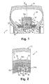
figure 1 est une vue en demi-coupe axiale d'un ensemble monté incorporant un dispositif de roulage à plat selon un premier mode de réalisation de l'invention incorporant des moyens de connexion rigides entre secteurs, - la
figure 2 est une vue en demi-coupe circonférentielle selon le plan II-II de lafigure 1 de cet ensemble monté, - la
figure 3 est une vue en perspective d'un secteur en arc de cercle de la structure annulaire de soutien du dispositif selon lafigure 1 , - la
figure 4 est une vue en perspective de la structure annulaire de soutien du dispositif selon lafigure 1 comportant deux secteurs selon lafigure 3 ayant été connectés entre eux, - la
figure 5 est une vue en perspective d'un secteur en arc de cercle d'une structure annulaire de soutien d'un dispositif de roulage à plat selon un second mode de réalisation de l'invention, - la
figure 6 est une vue en perspective éclatée de la structure de soutien d'un dispositif à trois secteurs selon lafigure 5 à connecter entre eux via des moyens de connexion rigides selon l'invention, qui sont également utilisables dans le premier mode de réalisation desfigures 1 à 4 , - la
figure 7 est une vue partielle en perspective éclatée d'une structure de soutien selon le second mode de l'invention dont les secteurs sont à connecter entre eux via des moyens de connexion rigides analogues à ceux de lafigure 6 et en outre par emboîtement de leurs extrémités en regard, - la
figure 8 est une vue partielle en perspective éclatée d'une structure de soutien selon le premier mode de l'invention dont les secteurs sont à connecter entre eux via les moyens de connexion rigides de lafigure 7 et par emboîtement de leurs extrémités en regard, - la
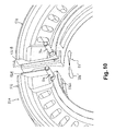
figure 9 est une vue partielle en perspective éclatée d'une structure de soutien selon ce premier mode correspondant à une variante de lafigure 8 , dont les secteurs sont à connecter entre eux via ces moyens de connexion rigides et par emboîtement de leurs extrémités en regard, et - la
figure 10 est une vue partielle en perspective éclatée d'une structure de soutien selon le second mode de l'invention dont les secteurs sont à connecter entre eux via des moyens de connexion déformables et en outre par emboîtement de leurs extrémités en regard.
- the
figure 1 is an axial half-sectional view of a mounted assembly incorporating a flatbed device according to a first embodiment of the invention incorporating rigid connection means between sectors, - the
figure 2 is a circumferential half-sectional view along plane II-II of thefigure 1 of this mounted assembly, - the
figure 3 is a perspective view of an arcuate sector of the annular support structure of the device according to thefigure 1 , - the
figure 4 is a perspective view of the annular support structure of the device according to thefigure 1 with two sectors according tofigure 3 having been connected to each other, - the
figure 5 is a perspective view of an arcuate sector of an annular support structure of a flatbed device according to a second embodiment of the invention, - the
figure 6 is an exploded perspective view of the support structure of a three-sector device according to thefigure 5 to connect between they via rigid connection means according to the invention, which can also be used in the first embodiment of the invention.Figures 1 to 4 , - the
figure 7 is a fragmentary exploded perspective view of a support structure according to the second embodiment of the invention, the sectors of which are to be connected to each other via rigid connection means similar to those of thefigure 6 and further by interlocking their ends facing each other, - the
figure 8 is a partial exploded perspective view of a support structure according to the first embodiment of the invention, the sectors of which are to be connected together via the rigid connection means of thefigure 7 and by nesting their ends opposite, - the
figure 9 is a partial exploded perspective view of a support structure according to this first mode corresponding to a variant of thefigure 8 , the sectors of which are to be connected to one another via these rigid connection means and by interlocking their opposite ends, and - the
figure 10 is a partial exploded perspective view of a support structure according to the second embodiment of the invention, the sectors of which are to be connected to each other via deformable connection means and further by interlocking their opposite ends.
Dans la présente description, les expressions « axialement interne » et « axialement externe » se réfèrent respectivement aux côtés de la jante de roue qui sont destinés à être tournés vers l'intérieur et vers l'extérieur du véhicule automobile, suite au montage sur un véhicule d'un ensemble monté comportant cette jante.In the present description, the terms "axially inner" and "axially outer" refer respectively to the sides of the wheel rim which are intended to be turned towards the inside and towards the outside of the motor vehicle, following assembly on a vehicle of a mounted assembly comprising this rim.
L'ensemble monté 1 selon l'invention qui est illustré à la
Les deux parties 10a et 10b comportent respectivement des rebords axialement interne et externe 12 et 13 délimitant respectivement deux sièges de jante 14 et 15 s'étendant axialement à partir des rebords 12 et 13, une enveloppe de pneumatique 20 dont les talons 21 et 22 sont montés en appui sur les sièges 14 et 15 contre les rebords 12 et 13, et un dispositif de roulage à plat 30 monté autour de la jante 10 à l'intérieur de l'enveloppe 20 et destiné à soutenir celle-ci suite à une chute de pression de gonflage à l'intérieur de l'ensemble monté 1.The two
Dans l'exemple de la
- une structure annulaire de soutien 31 qui est destinée à être montée sur la jante 10 en vue de soutenir l'enveloppe 20, suite à une chute de pression de gonflage à l'intérieur de l'ensemble monté 1, et qui est divisée en secteurs d'anneau 32 chacun en arc de cercle et de structure pleine qui sont articulés entre eux via des moyens de connexion 33 et qui sont adaptés pour former
la structure 31 par juxtaposition dans la direction circonférentielle de cette dernière, et - des cales annulaires 34 de blocage des talons 21 et 22 contre les rebords 12
et 13 qui sont destinés à relier lastructure 31 aux talons 21 et 22 et qui sont chacune d'un seul tenant, étant à base de caoutchouc renforcé par un élément de renforcement circonférentiel (non illustré),ces cales 34 étant appliquées latéralement sur une zone radialement intérieure des secteurs 32 située en regard des moyens de connexion 33, de sorte à les maintenir en position en roulage.
- an annular supporting
structure 31 which is intended to be mounted on therim 10 in order to support theenvelope 20, following an inflation pressure drop inside the mounted assembly 1, and which is divided into sectors ringmembers 32 each arcuate and solid structure which are hinged together via connection means 33 and which are adapted to form thestructure 31 by juxtaposition in the circumferential direction of the latter, and -
annular wedges 34 blocking theheels 21 and 22 against theflanges structure 31 to theheels 21 and 22 and which are each in one piece, being based on rubber reinforced by an element of circumferential reinforcement (not shown), thesewedges 34 being applied laterally to a radially inner zone of thesectors 32 facing the connection means 33, so as to maintain them in rolling position.
Chaque secteur d'anneau 32 est de préférence réalisé en un matériau composite, tel qu'une matrice de polyamide renforcée par une armature de fibres de verre, et il est selon ce premier mode de réalisation surmonté radialement d'un revêtement de protection 32a à base d'un caoutchouc de préférence de type rigide. On notera toutefois que ce revêtement 32a pourrait en variante être constitué d'un composite caoutchouc souple / éléments de renforcement.Each
Quant à la géométrie de chaque secteur d'anneau 32, elle présente à l'exemple de la
- dans ladite zone radialement intérieure sur laquelle appuient les cales de blocage 34, une section axiale sensiblement trapézoïdale qui s'élargit axialement au niveau de la face radialement interne du secteur 32 pour former une embase 32b de ce dernier et,
- dans une zone radialement extérieure surmontant la précédente, une section axiale sensiblement en forme de trapèze isocèle dont la grande base coïncide avec le revêtement de
protection 32a.
- in said radially inner zone on which the blocking
wedges 34 press, a substantially trapezoidal axial section which widens axially at the radially inner face of thesector 32 to form a base 32b thereof and, - in a radially outer zone surmounting the preceding one, an axial section substantially in the shape of an isosceles trapezium whose large base coincides with the
protective coating 32a.
Comme illustré aux
Plus précisément, on voit à la
Comme illustré à l'ensemble des
Comme illustré aux
Mais comme illustré aux
Pour réaliser le montage du dispositif de roulage à plat 30, 130 selon l'un ou l'autre de ces deux modes de réalisation, on procède avantageusement de la manière suivante :
- on commence par insérer les secteurs 32, 132 bout à bout et non connectés entre eux à l'intérieur de l'enveloppe de pneumatique 20 ;
- on met mutuellement en regard ces secteurs 32, 132 à l'intérieur de l'enveloppe 20, tant axialement et radialement que circonférentiellement,
- on connecte les secteurs 32, 132 entre eux à l'intérieur de l'enveloppe 20, via l'assemblage des moyens de connexion 33 (insertion de chaque patte 33b dans les évidements 32d, 132d entre deux secteurs 32, 132 et des axes 33a dans les logements 32f, 132f correspondants, axialement de part et d'autre de
ces évidements - on vient positionner les deux cales de blocage 34 axialement contre ces secteurs ainsi connectés et radialement en regard des axes 33a afin de les maintenir en position en roulage,
- on fait glisser le dispositif de roulage à
plat - on vient boulonner la partie axialement externe 10b de cette jante 10 sur la partie 10a.
- we begin by inserting the
sectors tire casing 20; - these
sectors casing 20, both axially and radially and circumferentially, - the
sectors envelope 20, via the assembly of the connection means 33 (insertion of eachtab 33b in therecesses sectors recesses - the two blocking
wedges 34 are positioned axially against these sectors thus connected and radially opposite theaxes 33a in order to keep them in rolling position, - the
flat rolling device inner portion 10a of the boltedrim 10, then - the axially
outer portion 10b of thisrim 10 is bolted to theportion 10a.
Comme indiqué précédemment, on notera que les secteurs 32, 132 ainsi articulés peuvent se déplacer réversiblement l'un par rapport à l'autre à la fois axialement et en torsion mutuelle, via le coulissement axial et le pivotement combinés de la patte ou goupille 33b sur les deux axes 33a et via la souplesse des cales de blocage 34, sous l'effet d'efforts latéraux de cisaillement ou de compression appliqués à l'enveloppe en roulage à plat ou à l'état gonflé.As indicated above, it will be noted that the
Les secteurs 232 illustrés à la
Les secteurs 332 illustrés à la
Les secteurs 432 illustrés à la
Les secteurs 532 illustrés à la
Claims (16)
Priority Applications (1)
| Application Number | Priority Date | Filing Date | Title |
|---|---|---|---|
| PL10189676T PL2322361T3 (en) | 2009-11-04 | 2010-11-02 | Run-flat support for motor vehicle and mounted assembly comprising same |
Applications Claiming Priority (1)
| Application Number | Priority Date | Filing Date | Title |
|---|---|---|---|
| FR0905284A FR2951994A1 (en) | 2009-11-04 | 2009-11-04 | FLAT ROLLING DEVICE FOR MOTOR VEHICLE AND MOUNTING ASSEMBLY INCORPORATING SAME |
Publications (2)
| Publication Number | Publication Date |
|---|---|
| EP2322361A1 true EP2322361A1 (en) | 2011-05-18 |
| EP2322361B1 EP2322361B1 (en) | 2013-08-21 |
Family
ID=42126417
Family Applications (1)
| Application Number | Title | Priority Date | Filing Date |
|---|---|---|---|
| EP10189676.9A Active EP2322361B1 (en) | 2009-11-04 | 2010-11-02 | Run-flat support for motor vehicle and mounted assembly comprising same |
Country Status (9)
| Country | Link |
|---|---|
| US (1) | US8978726B2 (en) |
| EP (1) | EP2322361B1 (en) |
| CA (1) | CA2719411C (en) |
| DK (1) | DK2322361T3 (en) |
| ES (1) | ES2434724T3 (en) |
| FR (1) | FR2951994A1 (en) |
| MY (1) | MY153490A (en) |
| PL (1) | PL2322361T3 (en) |
| SG (2) | SG190622A1 (en) |
Families Citing this family (10)
| Publication number | Priority date | Publication date | Assignee | Title |
|---|---|---|---|---|
| US20110297287A1 (en) * | 2010-06-04 | 2011-12-08 | Vianna Alexandre S | Applied to band for protection of vehicular wheels and tires |
| CN102785529B (en) * | 2011-05-18 | 2016-07-06 | 福建省密斯盾轮胎安全装置科技有限公司 | A kind of many rims stricture of vagina automotive tire burst safety device and installation method thereof |
| US10207544B2 (en) * | 2016-11-15 | 2019-02-19 | The Goodyear Tire & Rubber Company | Wheel for a support structure |
| CN106945472B (en) * | 2017-04-07 | 2019-08-23 | 吴联凯 | A kind of shoot proof tyre |
| US10457094B2 (en) * | 2017-12-11 | 2019-10-29 | The Goodyear Tire & Rubber Company | Wheel for a support structure |
| CN110525135B (en) * | 2018-05-24 | 2022-02-08 | 比亚迪股份有限公司 | Safety wheel and bogie with same |
| US11318791B2 (en) | 2019-11-15 | 2022-05-03 | The Goodyear Tire & Rubber Company | Wheel for a support structure |
| US11142022B2 (en) | 2019-11-15 | 2021-10-12 | The Goodyear Tire & Rubber Company | Support structure |
| US11124024B2 (en) | 2019-11-25 | 2021-09-21 | The Goodyear Tire & Rubber Company | Support structure |
| CN114475094A (en) * | 2022-02-16 | 2022-05-13 | 成都软科通证科技有限公司 | Tire, support ring thereof, support ring connecting structure and mounting method |
Citations (6)
| Publication number | Priority date | Publication date | Assignee | Title |
|---|---|---|---|---|
| DE820544C (en) * | 1948-10-02 | 1951-11-12 | Albert Philipp Von Hayn | Pneumatic tires for motor vehicles |
| JPS59156808A (en) * | 1983-02-23 | 1984-09-06 | Kawasaki Heavy Ind Ltd | Pneumatic-tired wheel with built-in auxiliary wheel and manufacturing method of auxiliary wheel |
| EP0233547A1 (en) | 1986-02-12 | 1987-08-26 | MICHELIN & CIE (Compagnie Générale des Etablissements Michelin) Société dite: | Safety device for emergency driving |
| WO2003106199A1 (en) * | 2002-06-17 | 2003-12-24 | Runflat International Limited | Two part run-flat device with shear pins |
| EP1541384A1 (en) | 2003-12-08 | 2005-06-15 | Hutchinson | Runflat supporting ring for vehicle and tire/wheel assembly including it |
| EP1588870A1 (en) | 2004-04-21 | 2005-10-26 | Société de Technologie Michelin | Runflat support for vehicle wheel |
Family Cites Families (2)
| Publication number | Priority date | Publication date | Assignee | Title |
|---|---|---|---|---|
| USRE32693E (en) * | 1982-07-26 | 1988-06-14 | Astronics Corporation | Safety liner for tires |
| FR2905631B1 (en) * | 2006-09-12 | 2008-11-28 | Hutchinson Sa | FLAT ROLLING DEVICE FOR MOTOR VEHICLE AND ASSEMBLY MOUNTING INCORPORATING SAME. |
-
2009
- 2009-11-04 FR FR0905284A patent/FR2951994A1/en not_active Withdrawn
-
2010
- 2010-11-02 EP EP10189676.9A patent/EP2322361B1/en active Active
- 2010-11-02 PL PL10189676T patent/PL2322361T3/en unknown
- 2010-11-02 DK DK10189676.9T patent/DK2322361T3/en active
- 2010-11-02 ES ES10189676T patent/ES2434724T3/en active Active
- 2010-11-03 CA CA2719411A patent/CA2719411C/en active Active
- 2010-11-03 MY MYPI2010005194A patent/MY153490A/en unknown
- 2010-11-03 US US12/938,514 patent/US8978726B2/en active Active
- 2010-11-03 SG SG2013033691A patent/SG190622A1/en unknown
- 2010-11-03 SG SG201008104-0A patent/SG170720A1/en unknown
Patent Citations (6)
| Publication number | Priority date | Publication date | Assignee | Title |
|---|---|---|---|---|
| DE820544C (en) * | 1948-10-02 | 1951-11-12 | Albert Philipp Von Hayn | Pneumatic tires for motor vehicles |
| JPS59156808A (en) * | 1983-02-23 | 1984-09-06 | Kawasaki Heavy Ind Ltd | Pneumatic-tired wheel with built-in auxiliary wheel and manufacturing method of auxiliary wheel |
| EP0233547A1 (en) | 1986-02-12 | 1987-08-26 | MICHELIN & CIE (Compagnie Générale des Etablissements Michelin) Société dite: | Safety device for emergency driving |
| WO2003106199A1 (en) * | 2002-06-17 | 2003-12-24 | Runflat International Limited | Two part run-flat device with shear pins |
| EP1541384A1 (en) | 2003-12-08 | 2005-06-15 | Hutchinson | Runflat supporting ring for vehicle and tire/wheel assembly including it |
| EP1588870A1 (en) | 2004-04-21 | 2005-10-26 | Société de Technologie Michelin | Runflat support for vehicle wheel |
Also Published As
| Publication number | Publication date |
|---|---|
| CA2719411A1 (en) | 2011-05-04 |
| US20110126955A1 (en) | 2011-06-02 |
| ES2434724T3 (en) | 2013-12-17 |
| CA2719411C (en) | 2016-07-26 |
| US8978726B2 (en) | 2015-03-17 |
| SG190622A1 (en) | 2013-06-28 |
| EP2322361B1 (en) | 2013-08-21 |
| FR2951994A1 (en) | 2011-05-06 |
| PL2322361T3 (en) | 2014-01-31 |
| SG170720A1 (en) | 2011-05-30 |
| DK2322361T3 (en) | 2013-11-25 |
| MY153490A (en) | 2015-02-13 |
Similar Documents
| Publication | Publication Date | Title |
|---|---|---|
| EP2322361B1 (en) | Run-flat support for motor vehicle and mounted assembly comprising same | |
| EP1897705B1 (en) | Run flat device for an automobile vehicle and installed assembly comprising same. | |
| CA2454982C (en) | Run-flat device for automobile and assembly incorporating it | |
| EP1359028B1 (en) | Non pneumatic elastic tyre | |
| CA2848707A1 (en) | Semi-hollow tire for agricultural machines, specifically for sowing machines | |
| EP0878328B1 (en) | Semi-tubular tyre and roller with such tyres | |
| WO2012010402A1 (en) | Non-pneumatic flexible tyre the bearing structure of which contains metal strips | |
| EP2206613B1 (en) | Runflat device for motor vehicle and assembly comprising same | |
| EP3017669B2 (en) | Improved agricultural wheel | |
| EP0600771A1 (en) | Annular device improved for flat running | |
| EP3478519B1 (en) | Run-flat device | |
| EP1380198B1 (en) | Draft frame agricultural machine with dome shaped tire roller | |
| EP0912354B1 (en) | Inflatable structure for a tyre | |
| FR2859662A1 (en) | METHOD FOR LAUNCHING A MOTOR VEHICLE WHEEL FLAT ROLLING DEVICE AND DEVICE THUS OBTAINED | |
| FR2861649A1 (en) | FRAGMENT SECURITY SUPPORT | |
| WO2018234703A1 (en) | Tyre type device for vehicle | |
| EP1538007B1 (en) | Run flat device for motor vehicle and mounted assembly including it | |
| FR2617441A1 (en) | IMPROVED FLAT RUNNING DEVICE | |
| EP3642052B1 (en) | Tyre type device for vehicle | |
| EP4331867A1 (en) | Deformable wheel with non-pneumatic load support for conditions on the moon and mars | |
| FR3100500A1 (en) | VEHICLE SAFETY DEVICE | |
| FR2903047A1 (en) | Running flat device for motor vehicle, has textile wall delimiting annular compartment with locking units, and support portion with circumferential support unit on its inner side for taking back force applied to support unit by flanges | |
| EP2539601A1 (en) | Articulated composite spring leaf for the ground contact system of a motor vehicle, method of manufacture thereof and ground contact system created | |
| FR2550493A1 (en) | Improvements to wheels with elastic spokes with a view to increasing the adherence of a vehicle on all terrains | |
| FR2843334A1 (en) | Safety support for deflated pneumatic tire comprises inner ring with mechanism to retain tire edges on wheel rim |
Legal Events
| Date | Code | Title | Description |
|---|---|---|---|
| PUAI | Public reference made under article 153(3) epc to a published international application that has entered the european phase |
Free format text: ORIGINAL CODE: 0009012 |
|
| AK | Designated contracting states |
Kind code of ref document: A1 Designated state(s): AL AT BE BG CH CY CZ DE DK EE ES FI FR GB GR HR HU IE IS IT LI LT LU LV MC MK MT NL NO PL PT RO RS SE SI SK SM TR |
|
| AX | Request for extension of the european patent |
Extension state: BA ME |
|
| 17P | Request for examination filed |
Effective date: 20110606 |
|
| 17Q | First examination report despatched |
Effective date: 20120516 |
|
| GRAP | Despatch of communication of intention to grant a patent |
Free format text: ORIGINAL CODE: EPIDOSNIGR1 |
|
| INTG | Intention to grant announced |
Effective date: 20130328 |
|
| GRAS | Grant fee paid |
Free format text: ORIGINAL CODE: EPIDOSNIGR3 |
|
| GRAA | (expected) grant |
Free format text: ORIGINAL CODE: 0009210 |
|
| AK | Designated contracting states |
Kind code of ref document: B1 Designated state(s): AL AT BE BG CH CY CZ DE DK EE ES FI FR GB GR HR HU IE IS IT LI LT LU LV MC MK MT NL NO PL PT RO RS SE SI SK SM TR |
|
| REG | Reference to a national code |
Ref country code: GB Ref legal event code: FG4D Free format text: NOT ENGLISH |
|
| REG | Reference to a national code |
Ref country code: CH Ref legal event code: EP |
|
| REG | Reference to a national code |
Ref country code: AT Ref legal event code: REF Ref document number: 627826 Country of ref document: AT Kind code of ref document: T Effective date: 20130915 |
|
| REG | Reference to a national code |
Ref country code: IE Ref legal event code: FG4D Free format text: LANGUAGE OF EP DOCUMENT: FRENCH |
|
| REG | Reference to a national code |
Ref country code: DE Ref legal event code: R096 Ref document number: 602010009596 Country of ref document: DE Effective date: 20131017 |
|
| REG | Reference to a national code |
Ref country code: CH Ref legal event code: NV Representative=s name: ISLER AND PEDRAZZINI AG, CH |
|
| REG | Reference to a national code |
Ref country code: DK Ref legal event code: T3 Effective date: 20131119 |
|
| REG | Reference to a national code |
Ref country code: NL Ref legal event code: T3 |
|
| REG | Reference to a national code |
Ref country code: ES Ref legal event code: FG2A Ref document number: 2434724 Country of ref document: ES Kind code of ref document: T3 Effective date: 20131217 |
|
| REG | Reference to a national code |
Ref country code: LT Ref legal event code: MG4D |
|
| PG25 | Lapsed in a contracting state [announced via postgrant information from national office to epo] |
Ref country code: IS Free format text: LAPSE BECAUSE OF FAILURE TO SUBMIT A TRANSLATION OF THE DESCRIPTION OR TO PAY THE FEE WITHIN THE PRESCRIBED TIME-LIMIT Effective date: 20131221 Ref country code: LT Free format text: LAPSE BECAUSE OF FAILURE TO SUBMIT A TRANSLATION OF THE DESCRIPTION OR TO PAY THE FEE WITHIN THE PRESCRIBED TIME-LIMIT Effective date: 20130821 Ref country code: HR Free format text: LAPSE BECAUSE OF FAILURE TO SUBMIT A TRANSLATION OF THE DESCRIPTION OR TO PAY THE FEE WITHIN THE PRESCRIBED TIME-LIMIT Effective date: 20130821 Ref country code: PT Free format text: LAPSE BECAUSE OF FAILURE TO SUBMIT A TRANSLATION OF THE DESCRIPTION OR TO PAY THE FEE WITHIN THE PRESCRIBED TIME-LIMIT Effective date: 20131223 Ref country code: NO Free format text: LAPSE BECAUSE OF FAILURE TO SUBMIT A TRANSLATION OF THE DESCRIPTION OR TO PAY THE FEE WITHIN THE PRESCRIBED TIME-LIMIT Effective date: 20131121 Ref country code: CY Free format text: LAPSE BECAUSE OF FAILURE TO SUBMIT A TRANSLATION OF THE DESCRIPTION OR TO PAY THE FEE WITHIN THE PRESCRIBED TIME-LIMIT Effective date: 20130717 Ref country code: SE Free format text: LAPSE BECAUSE OF FAILURE TO SUBMIT A TRANSLATION OF THE DESCRIPTION OR TO PAY THE FEE WITHIN THE PRESCRIBED TIME-LIMIT Effective date: 20130821 |
|
| REG | Reference to a national code |
Ref country code: PL Ref legal event code: T3 |
|
| PG25 | Lapsed in a contracting state [announced via postgrant information from national office to epo] |
Ref country code: LV Free format text: LAPSE BECAUSE OF FAILURE TO SUBMIT A TRANSLATION OF THE DESCRIPTION OR TO PAY THE FEE WITHIN THE PRESCRIBED TIME-LIMIT Effective date: 20130821 Ref country code: GR Free format text: LAPSE BECAUSE OF FAILURE TO SUBMIT A TRANSLATION OF THE DESCRIPTION OR TO PAY THE FEE WITHIN THE PRESCRIBED TIME-LIMIT Effective date: 20131122 Ref country code: SI Free format text: LAPSE BECAUSE OF FAILURE TO SUBMIT A TRANSLATION OF THE DESCRIPTION OR TO PAY THE FEE WITHIN THE PRESCRIBED TIME-LIMIT Effective date: 20130821 |
|
| PG25 | Lapsed in a contracting state [announced via postgrant information from national office to epo] |
Ref country code: CY Free format text: LAPSE BECAUSE OF FAILURE TO SUBMIT A TRANSLATION OF THE DESCRIPTION OR TO PAY THE FEE WITHIN THE PRESCRIBED TIME-LIMIT Effective date: 20130821 |
|
| PG25 | Lapsed in a contracting state [announced via postgrant information from national office to epo] |
Ref country code: CZ Free format text: LAPSE BECAUSE OF FAILURE TO SUBMIT A TRANSLATION OF THE DESCRIPTION OR TO PAY THE FEE WITHIN THE PRESCRIBED TIME-LIMIT Effective date: 20130821 Ref country code: RO Free format text: LAPSE BECAUSE OF FAILURE TO SUBMIT A TRANSLATION OF THE DESCRIPTION OR TO PAY THE FEE WITHIN THE PRESCRIBED TIME-LIMIT Effective date: 20130821 Ref country code: EE Free format text: LAPSE BECAUSE OF FAILURE TO SUBMIT A TRANSLATION OF THE DESCRIPTION OR TO PAY THE FEE WITHIN THE PRESCRIBED TIME-LIMIT Effective date: 20130821 Ref country code: SK Free format text: LAPSE BECAUSE OF FAILURE TO SUBMIT A TRANSLATION OF THE DESCRIPTION OR TO PAY THE FEE WITHIN THE PRESCRIBED TIME-LIMIT Effective date: 20130821 |
|
| BERE | Be: lapsed |
Owner name: HUTCHINSON Effective date: 20131130 |
|
| PLBE | No opposition filed within time limit |
Free format text: ORIGINAL CODE: 0009261 |
|
| STAA | Information on the status of an ep patent application or granted ep patent |
Free format text: STATUS: NO OPPOSITION FILED WITHIN TIME LIMIT |
|
| 26N | No opposition filed |
Effective date: 20140522 |
|
| PG25 | Lapsed in a contracting state [announced via postgrant information from national office to epo] |
Ref country code: MC Free format text: LAPSE BECAUSE OF FAILURE TO SUBMIT A TRANSLATION OF THE DESCRIPTION OR TO PAY THE FEE WITHIN THE PRESCRIBED TIME-LIMIT Effective date: 20130821 |
|
| REG | Reference to a national code |
Ref country code: IE Ref legal event code: MM4A |
|
| REG | Reference to a national code |
Ref country code: DE Ref legal event code: R097 Ref document number: 602010009596 Country of ref document: DE Effective date: 20140522 |
|
| PG25 | Lapsed in a contracting state [announced via postgrant information from national office to epo] |
Ref country code: BE Free format text: LAPSE BECAUSE OF NON-PAYMENT OF DUE FEES Effective date: 20131130 |
|
| PG25 | Lapsed in a contracting state [announced via postgrant information from national office to epo] |
Ref country code: IE Free format text: LAPSE BECAUSE OF NON-PAYMENT OF DUE FEES Effective date: 20131102 |
|
| PG25 | Lapsed in a contracting state [announced via postgrant information from national office to epo] |
Ref country code: SM Free format text: LAPSE BECAUSE OF FAILURE TO SUBMIT A TRANSLATION OF THE DESCRIPTION OR TO PAY THE FEE WITHIN THE PRESCRIBED TIME-LIMIT Effective date: 20130821 |
|
| PG25 | Lapsed in a contracting state [announced via postgrant information from national office to epo] |
Ref country code: RS Free format text: LAPSE BECAUSE OF FAILURE TO SUBMIT A TRANSLATION OF THE DESCRIPTION OR TO PAY THE FEE WITHIN THE PRESCRIBED TIME-LIMIT Effective date: 20131121 Ref country code: BG Free format text: LAPSE BECAUSE OF FAILURE TO SUBMIT A TRANSLATION OF THE DESCRIPTION OR TO PAY THE FEE WITHIN THE PRESCRIBED TIME-LIMIT Effective date: 20130821 Ref country code: HU Free format text: LAPSE BECAUSE OF FAILURE TO SUBMIT A TRANSLATION OF THE DESCRIPTION OR TO PAY THE FEE WITHIN THE PRESCRIBED TIME-LIMIT; INVALID AB INITIO Effective date: 20101102 Ref country code: MK Free format text: LAPSE BECAUSE OF FAILURE TO SUBMIT A TRANSLATION OF THE DESCRIPTION OR TO PAY THE FEE WITHIN THE PRESCRIBED TIME-LIMIT Effective date: 20130821 Ref country code: LU Free format text: LAPSE BECAUSE OF NON-PAYMENT OF DUE FEES Effective date: 20131102 |
|
| PG25 | Lapsed in a contracting state [announced via postgrant information from national office to epo] |
Ref country code: MT Free format text: LAPSE BECAUSE OF FAILURE TO SUBMIT A TRANSLATION OF THE DESCRIPTION OR TO PAY THE FEE WITHIN THE PRESCRIBED TIME-LIMIT Effective date: 20130821 |
|
| REG | Reference to a national code |
Ref country code: FR Ref legal event code: PLFP Year of fee payment: 6 |
|
| REG | Reference to a national code |
Ref country code: FR Ref legal event code: PLFP Year of fee payment: 7 |
|
| REG | Reference to a national code |
Ref country code: FR Ref legal event code: PLFP Year of fee payment: 8 |
|
| REG | Reference to a national code |
Ref country code: FR Ref legal event code: PLFP Year of fee payment: 9 |
|
| PG25 | Lapsed in a contracting state [announced via postgrant information from national office to epo] |
Ref country code: AL Free format text: LAPSE BECAUSE OF FAILURE TO SUBMIT A TRANSLATION OF THE DESCRIPTION OR TO PAY THE FEE WITHIN THE PRESCRIBED TIME-LIMIT Effective date: 20130821 |
|
| PGFP | Annual fee paid to national office [announced via postgrant information from national office to epo] |
Ref country code: ES Payment date: 20230125 Year of fee payment: 13 |
|
| P01 | Opt-out of the competence of the unified patent court (upc) registered |
Effective date: 20230526 |
|
| PGFP | Annual fee paid to national office [announced via postgrant information from national office to epo] |
Ref country code: NL Payment date: 20231120 Year of fee payment: 14 |
|
| PGFP | Annual fee paid to national office [announced via postgrant information from national office to epo] |
Ref country code: GB Payment date: 20231123 Year of fee payment: 14 |
|
| PGFP | Annual fee paid to national office [announced via postgrant information from national office to epo] |
Ref country code: TR Payment date: 20231030 Year of fee payment: 14 Ref country code: IT Payment date: 20231124 Year of fee payment: 14 Ref country code: FR Payment date: 20231120 Year of fee payment: 14 Ref country code: FI Payment date: 20231121 Year of fee payment: 14 Ref country code: DK Payment date: 20231124 Year of fee payment: 14 Ref country code: DE Payment date: 20231121 Year of fee payment: 14 Ref country code: CH Payment date: 20231201 Year of fee payment: 14 Ref country code: AT Payment date: 20231121 Year of fee payment: 14 |
|
| PGFP | Annual fee paid to national office [announced via postgrant information from national office to epo] |
Ref country code: PL Payment date: 20231020 Year of fee payment: 14 |
|
| PGFP | Annual fee paid to national office [announced via postgrant information from national office to epo] |
Ref country code: ES Payment date: 20240126 Year of fee payment: 14 |