EP2320441A1 - Assembly aid for punch laminations - Google Patents
Assembly aid for punch laminations Download PDFInfo
- Publication number
- EP2320441A1 EP2320441A1 EP10188988A EP10188988A EP2320441A1 EP 2320441 A1 EP2320441 A1 EP 2320441A1 EP 10188988 A EP10188988 A EP 10188988A EP 10188988 A EP10188988 A EP 10188988A EP 2320441 A1 EP2320441 A1 EP 2320441A1
- Authority
- EP
- European Patent Office
- Prior art keywords
- slugs
- geometry
- sheets
- slug
- holes
- Prior art date
- Legal status (The legal status is an assumption and is not a legal conclusion. Google has not performed a legal analysis and makes no representation as to the accuracy of the status listed.)
- Withdrawn
Links
Images


Classifications
-
- B—PERFORMING OPERATIONS; TRANSPORTING
- B21—MECHANICAL METAL-WORKING WITHOUT ESSENTIALLY REMOVING MATERIAL; PUNCHING METAL
- B21D—WORKING OR PROCESSING OF SHEET METAL OR METAL TUBES, RODS OR PROFILES WITHOUT ESSENTIALLY REMOVING MATERIAL; PUNCHING METAL
- B21D39/00—Application of procedures in order to connect objects or parts, e.g. coating with sheet metal otherwise than by plating; Tube expanders
- B21D39/03—Application of procedures in order to connect objects or parts, e.g. coating with sheet metal otherwise than by plating; Tube expanders of sheet metal otherwise than by folding
- B21D39/031—Joining superposed plates by locally deforming without slitting or piercing
- B21D39/032—Joining superposed plates by locally deforming without slitting or piercing by fitting a projecting part integral with one plate in a hole of the other plate
-
- B—PERFORMING OPERATIONS; TRANSPORTING
- B21—MECHANICAL METAL-WORKING WITHOUT ESSENTIALLY REMOVING MATERIAL; PUNCHING METAL
- B21D—WORKING OR PROCESSING OF SHEET METAL OR METAL TUBES, RODS OR PROFILES WITHOUT ESSENTIALLY REMOVING MATERIAL; PUNCHING METAL
- B21D28/00—Shaping by press-cutting; Perforating
- B21D28/02—Punching blanks or articles with or without obtaining scrap; Notching
- B21D28/14—Dies
- B21D28/145—Dies with means for slug retention, e.g. a groove
-
- B—PERFORMING OPERATIONS; TRANSPORTING
- B21—MECHANICAL METAL-WORKING WITHOUT ESSENTIALLY REMOVING MATERIAL; PUNCHING METAL
- B21D—WORKING OR PROCESSING OF SHEET METAL OR METAL TUBES, RODS OR PROFILES WITHOUT ESSENTIALLY REMOVING MATERIAL; PUNCHING METAL
- B21D43/00—Feeding, positioning or storing devices combined with, or arranged in, or specially adapted for use in connection with, apparatus for working or processing sheet metal, metal tubes or metal profiles; Associations therewith of cutting devices
- B21D43/20—Storage arrangements; Piling or unpiling
- B21D43/22—Devices for piling sheets
-
- H—ELECTRICITY
- H01—ELECTRIC ELEMENTS
- H01F—MAGNETS; INDUCTANCES; TRANSFORMERS; SELECTION OF MATERIALS FOR THEIR MAGNETIC PROPERTIES
- H01F41/00—Apparatus or processes specially adapted for manufacturing or assembling magnets, inductances or transformers; Apparatus or processes specially adapted for manufacturing materials characterised by their magnetic properties
- H01F41/02—Apparatus or processes specially adapted for manufacturing or assembling magnets, inductances or transformers; Apparatus or processes specially adapted for manufacturing materials characterised by their magnetic properties for manufacturing cores, coils, or magnets
- H01F41/0206—Manufacturing of magnetic cores by mechanical means
- H01F41/0233—Manufacturing of magnetic circuits made from sheets
- H01F41/024—Manufacturing of magnetic circuits made from deformed sheets
Definitions
- the invention relates to a method for improving the accuracy of stanzp elected laminated cores, in particular of stanzp elected electrical steel cores.
- the punching package of sheets is a example of the EP0133858 A1 Known method for producing laminated cores in a single operation.
- the individual sheets cut out in a known progressive tool are stacked on top of one another and joined together by an integrated method described in more detail below in the tool.
- slugs are punched by an embossing process, leaving a slug hole in the form of a blind hole in the single sheet. In this hole, the slugs of the individual sheet produced in the next punching are pressed during the cutting process.
- the strength of the resulting composite sheet is dependent on the clamping force with which the slugs sit in the Butzenlöchern, which in turn depends on the dimensions of slugs and Butzenlöchern. These dimensions must be in close tolerances and their temporal consistency depends on various factors such as tool wear and tolerances in the material properties of the sheets. In addition, the slugs must be manufactured and joined with sufficient positioning accuracy with respect to the slug holes. If the rigorous Gebung from Butzen to Butzenloch too low, the composite sheet can separate again.
- the invention is therefore an object of the invention to improve the process of Stanzbierens such that the committee or the required rework is minimized by mutually releasing sheets and non-plane-parallel laminated cores.
- the slugs can be pre-embossed for better dimensional stability, the slug holes are pre-punched accordingly.
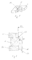
- Fig. 1 is an advantageous embodiment of a located in a first side of a single sheet Butzenlochs (10) with three distributed over the outer circumference, in the otherwise circular cross-section of the Butzenlochs protruding lugs (11) to see.
- a circular slug (15) can be seen on the opposite second side of the single sheet.
- Fig. 2 is a section of a Butzen- or Butzenlochgargestation a follow-on composite tool for producing inventive single sheets with a recess (53) for forming a nose (11) providing embossing punch (50), a hold-down (55) and a male (56) to see ,
- the single sheet (1) lies above the bore (57) in the male part (56).
- the pressure of the descending stamping die (50) of the slug (15) and the slug hole (10) is embossed.
- the diameter of the bore (57) and thus the outer diameter of the slugs (15) is greater than the pitch circle diameter (54) of the lugs, but smaller than the foot diameter (12) of the Butzenlochs (10).
- the slugs (15) clamp on the lugs (11), which they plastically deform when pressed in the nerierstation the follow-on composite tool (not shown).
- the noses (11) can thereby flow into the gap, which results from the difference between the outer diameter of the Butzens and the base diameter (12) of the Butzenlochs (10).
- Fig. 3 schematically shows a laminated core, which consists of the stamping of the slugs (15) in the corresponding slug holes (10) interconnected individual sheets.
- Fig. 4 shows a section of a single sheet with embossed Butzenloch (10) and three evenly distributed over the hole circumference lugs (11) in plan view. Evident are the foot diameter (12) and pitch circle diameter (54).
- Fig. 5 is the corresponding die (50) of the follow-on composite tool with recesses (53) to see the formation of the noses.
- the invention is not limited to the embodiment with lugs (11) in the slotted hole (10).
- lugs (11) in the slotted hole (10).
- a Dahlberggeometrie in Butzenloch denkar instead of the noses a Dahlberggeometrie in Butzenloch denkar. It is also conceivable to attach the toothing on the outer diameter of the Butzens 15 and to equip the Butzenloch circular or also with a tooth geometry.
Landscapes
- Engineering & Computer Science (AREA)
- Mechanical Engineering (AREA)
- Perforating, Stamping-Out Or Severing By Means Other Than Cutting (AREA)
Abstract
Description
Die Erfindung betrifft ein Verfahren zur Verbesserung der Genauigkeit von stanzpaketierten Blechpaketen, insbesondere von stanzpaketierten Elektroblechpaketen.The invention relates to a method for improving the accuracy of stanzpaketierten laminated cores, in particular of stanzpaketierten electrical steel cores.
Das Stanzpaketieren von Blechen ist ein z.B. aus der
Auch aus der
Der Erfindung liegt somit die Aufgabe zugrunde, das Verfahren des Stanzpaketierens dergestalt zu verbessern, dass der Ausschuss bzw. die erforderliche Nacharbeit durch sich voneinander lösende Bleche und durch nicht planparallele Blechpakete minimiert wird. Ausgehend von dem Verfahren der eingangs genannten Art wird die Aufgabe erfindungsgemäß durch die Merkmale der unabgängigen Ansprüche gelöst, während den abhängigen Ansprüchen vorteilhafte Ausgestaltungen der Erfindung zu entnehmen sind.The invention is therefore an object of the invention to improve the process of Stanzpaketierens such that the committee or the required rework is minimized by mutually releasing sheets and non-plane-parallel laminated cores. Starting from the method of the type mentioned, the object is achieved by the features of the unabgängigen claims, while the dependent claims advantageous embodiments of the invention are apparent.
Durch die Verwendung einer unterschiedlichen und geeignet anders geformten Umfangsgeometrie von Butzen zu Butzenloch, wird der Butzen beim Eindrücken in das Butzenloch plastisch verformt, wodurch nur geringe Rückstellkräfte auftreten, die den Butzen bei einer nicht ganz exakten Positionierung von Butzen zu Butzenloch in die zentrische Lage des Butzenloches zurück zu drücken versuchen. Dabei sind Geoemtriepaarungen wie Vielzahngeometrie des Butzens und runde Geometrie des Butzenlochs, ovale Geometrie des Butzens und runde Geometrie des Butzenlochs oder runde Geometrie Butzens und ovale Geometrie des Butzenlochs, sowie andere Kombinationen wie ovale oder runde Butzen in Butzenlöchern mit Vielzahngeometrie denkbar. Die Planparallelität von Ober- und Unterseite des Blechpakets bleibt so weitestgehend erhalten. Andererseits reicht die plastische Verformung der Butzen aus, dass sich die Klemmkraft in Form von kraft- und formschlüssiger Verbindung zwischen Butzen und Butzenloch auf einem solchen Niveau bewegt, dass eine sichere Verbindung zwischen den Blechen gegeben ist.Through the use of a different and suitably differently shaped peripheral geometry of slug to Butzenloch, the slug is plastically deformed when pressed into the slug hole, causing only small restoring forces occur, the slug at a not exactly exact positioning of slugs to Butzenloch in the centric position of the Try to push back Butzenloches. Geoemtrie pairings such as multi-tooth geometry of Butzens and round geometry of Butzenlochs, oval geometry of the Butzens and round geometry of Butzenlochs or round geometry Butzens and oval geometry of the Butzenlochs, and other combinations such as oval or round slugs in Butzenlöchern with multi-tooth geometry conceivable. The parallelism of the top and bottom of the laminated core remains as far as possible. On the other hand, the plastic deformation of the slugs is sufficient that the clamping force in the form of non-positive and positive connection between slug and slug hole moves to such a level that a secure connection between the sheets is given.
Die Butzen können zur besseren Maßhaltigkeit vorgeprägt, die Butzenlöcher entsprechend vorgelocht werden.The slugs can be pre-embossed for better dimensional stability, the slug holes are pre-punched accordingly.
Zur Herstellung der so geformten Bleche wird die Verwendung eines Folgeverbundwerkzeugs, das in eine handelsübliche Presse eingebaut werden kann, vorgeschlagen, das in mehreren Arbeitsstationen bei jedem Hub der Presse zeitgleich die Geometrien formt und ausschneidet, die Bleche aufstapelt und jede Lage durch Verprägen der jeweils ein oder mehreren Butzen in den jeweiligen ein oder mehreren Butzenlöchern mit der vorherigen Lage eines Blechstapels verbindet.To produce the sheets thus formed, the use of a follow-on composite tool that can be installed in a commercial press, proposed in several workstations at each stroke of the press at the same time Shaping and cutting out geometries, stacking the sheets and bonding each sheet to the previous sheet stack position by stamping each one or more slugs in the respective one or more slug holes.
Weitere Einzelheiten und Vorteile der Erfindung ergeben sich aus den folgenden, anhand von Figuren erläuterten Ausführungsbeispielen. Es zeigen
-
Fig. 1 einen Ausschnitt aus einem Blech mit einem Butzenloch in perspektivischer Darstellung; -
Fig. 2 einen Ausschnitt aus der Butzen- bzw. Butzenlochprägestation eines Folgeverbundwerkzeugs im Schnitt; -
Fig. 3 einen Ausschnitt aus einem Blechpaket schematisch; -
Fig. 4 einen Ausschnitt aus einem Einzelblech in der Draufsicht; -
Fig. 5 einen Butzenlochstempel; -
Fig. 6 einen Ausschnitt aus der Patrize.
-
Fig. 1 a section of a metal sheet with a Butzenloch in perspective view; -
Fig. 2 a section of the slug or Butzenlochprägestation a follow-on composite tool in section; -
Fig. 3 a section of a laminated core schematically; -
Fig. 4 a section of a single sheet in plan view; -
Fig. 5 a cancel hole stamp; -
Fig. 6 a section of the patrix.
In
In
In
Selbstverständlich ist die Erfindung nicht auf die Ausführung mit Nasen (11) im Butzenloch (10) beschränkt. Ebenfalls ist statt der Nasen eine Vielzahngeometrie im Butzenloch denkar. Auch ist es denkbar, die Verzahnung am Außendurchmesser des Butzens 15 anzubringen und das Butzenloch kreisrund oder ebenfalls mit einer Verzahnungsgeometrie auszustatten.Of course, the invention is not limited to the embodiment with lugs (11) in the slotted hole (10). Also, instead of the noses a Vielzahngeometrie in Butzenloch denkar. It is also conceivable to attach the toothing on the outer diameter of the
- 11
- EinzelblechSingle sheet
- 1010
- ButzenlochButzenloch
- 1111
- Nasenose
- 1212
- FußdurchmesserBase diameter
- 1515
- Butzenslugs
- 5050
- Prägestempeldies
- 5353
- Ausnehmungrecess
- 5454
- TeilkreisdurchmesserPitch diameter
- 5555
- NiederhalterStripper plate
- 5656
- Patrizepunch
- 5757
- Bohrungdrilling
Claims (8)
dadurch gekennzeichnet, dass
die Umfangsgeometrien von Butzenloch und Butzen unterschiedlich sind.A process for the production of packages consisting of two or more stacked sheets, wherein the sheets of sheet metal strip punched in one operation, provided with recessed Butzenlöchern on the one and elevations in the form of slugs on the other side and layered in the same operation, wherein the slugs be pressed into the stud holes,
characterized in that
the peripheral geometries of Butzenloch and Butzen are different.
dadurch gekennzeichnet, dass
die Butzen eine runde Geometrie, die Butzenlöcher hingegen eine Vielzahngeometrie aufweisen.Method according to claim 1,
characterized in that
the slugs have a round geometry, while the slug holes have a multi-tooth geometry.
dadurch gekennzeichnet, dass
die Butzenlöcher eine runde Geometrie, die Butzen hingegen eine Vielzahngeometrie aufweisen.Method according to claim 1,
characterized in that
the slug holes have a round geometry, while the slugs have a multi-tooth geometry.
dadurch gekennzeichnet, dass
die Butzen eine runde Geometrie, die Butzenlöcher hingegen eine ovale Geometrie aufweisen.Method according to claim 1,
characterized in that
the slugs have a round geometry, while the slug holes have an oval geometry.
dadurch gekennzeichnet, dass
die Butzenlöcher eine runde Geometrie, die Butzen hingegen eine ovale Geometrie aufweisen.Method according to claim 1,
characterized in that
the slug holes have a round geometry, while the slugs have an oval geometry.
dadurch gekennzeichnet, dass
die Butzenlöcher und die Butzen vorgeprägt oder vorgelocht werden.Method according to claims 1 to 5,
characterized in that
the slug holes and the slugs are pre-stamped or pre-punched.
dadurch gekennzeichnet, dass
die Matrize zur Herstellung des Butzens und der Stempel zur Formung des Butzenlochs unterschiedliche Geometrien aufweisen.Apparatus for carrying out the method according to claims 1 to 6, comprising at least one die and one male with a punch for forming slugs and a slug hole,
characterized in that
the die for producing the Butzens and the punch for forming the Butzenlochs have different geometries.
dadurch gekennzeichnet, dass
Stempel und Matrize eine Maßüberdeckung aufweisen.Device according to claim 7,
characterized in that
Stamp and die have a Maßüberdeckung.
Applications Claiming Priority (1)
| Application Number | Priority Date | Filing Date | Title |
|---|---|---|---|
| DE200910051271 DE102009051271A1 (en) | 2009-10-29 | 2009-10-29 | Assembly aid for punching package |
Publications (1)
| Publication Number | Publication Date |
|---|---|
| EP2320441A1 true EP2320441A1 (en) | 2011-05-11 |
Family
ID=43769046
Family Applications (1)
| Application Number | Title | Priority Date | Filing Date |
|---|---|---|---|
| EP10188988A Withdrawn EP2320441A1 (en) | 2009-10-29 | 2010-10-27 | Assembly aid for punch laminations |
Country Status (2)
| Country | Link |
|---|---|
| EP (1) | EP2320441A1 (en) |
| DE (1) | DE102009051271A1 (en) |
Cited By (3)
| Publication number | Priority date | Publication date | Assignee | Title |
|---|---|---|---|---|
| ITMI20120356A1 (en) * | 2012-03-07 | 2013-09-08 | Corrada Spa | BLANKING MOLD WITH ANTI-SPRAY BRAKING DEVICE |
| CN105689541A (en) * | 2014-12-16 | 2016-06-22 | 铃木株式会社 | Punch for mechanical connection, mechanical connection device and mechnical connection member |
| DE102015121951A1 (en) | 2015-12-16 | 2017-06-22 | Kiekert Ag | Method for producing a motor vehicle door lock |
Families Citing this family (1)
| Publication number | Priority date | Publication date | Assignee | Title |
|---|---|---|---|---|
| DE102018107916A1 (en) * | 2018-04-04 | 2019-10-10 | Iav Gmbh Ingenieurgesellschaft Auto Und Verkehr | Method and device for producing an electrical sheet of an electrical machine |
Citations (6)
| Publication number | Priority date | Publication date | Assignee | Title |
|---|---|---|---|---|
| EP0133858A1 (en) | 1983-08-12 | 1985-03-13 | Essa Fabrique de Machines S.A. | Method of and device for manufacturing packets made of sheet plates for magnetic cores of electric machines |
| US4728842A (en) * | 1986-09-29 | 1988-03-01 | Carbet Corporation | Laminated assembly for a dynamoelectric machine and method for manufacturing laminated assemblies having ridges formed on projections which interlock with recesses of adjacent laminations |
| US4809429A (en) * | 1986-09-29 | 1989-03-07 | Carbet Corporation | Apparatus for manufacturing laminated assemblies having ridges formed on projections which interlock with recesses of adjacent laminations |
| US5230136A (en) * | 1992-05-04 | 1993-07-27 | Savair Inc. | Punch and die set for sheet metal clinching |
| WO1999016092A1 (en) | 1997-09-19 | 1999-04-01 | Vacuumschmelze Gmbh | Method and device for producing bundles of sheet metal laminates for magnetic cores |
| WO2003041889A1 (en) * | 2001-11-13 | 2003-05-22 | Empresa Brasileira De Compressores S/A - Embraco | A metallic lamination, a stack of metallic laminations and packing method therefor |
Family Cites Families (4)
| Publication number | Priority date | Publication date | Assignee | Title |
|---|---|---|---|---|
| US2671951A (en) * | 1949-10-03 | 1954-03-16 | Jefferson Electric Co | Transformer core and method of making same |
| DE1021516B (en) * | 1956-04-28 | 1957-12-27 | Kloeckner Moeller Elektrizit | Method for manufacturing AC magnetic cores |
| US2975312A (en) * | 1958-03-07 | 1961-03-14 | Globe Union Inc | Laminated magneto components |
| GB2206453B (en) * | 1987-06-22 | 1992-01-02 | Linton & Hirst Ltd | Pack of laminations and forming projections and depressions |
-
2009
- 2009-10-29 DE DE200910051271 patent/DE102009051271A1/en not_active Withdrawn
-
2010
- 2010-10-27 EP EP10188988A patent/EP2320441A1/en not_active Withdrawn
Patent Citations (6)
| Publication number | Priority date | Publication date | Assignee | Title |
|---|---|---|---|---|
| EP0133858A1 (en) | 1983-08-12 | 1985-03-13 | Essa Fabrique de Machines S.A. | Method of and device for manufacturing packets made of sheet plates for magnetic cores of electric machines |
| US4728842A (en) * | 1986-09-29 | 1988-03-01 | Carbet Corporation | Laminated assembly for a dynamoelectric machine and method for manufacturing laminated assemblies having ridges formed on projections which interlock with recesses of adjacent laminations |
| US4809429A (en) * | 1986-09-29 | 1989-03-07 | Carbet Corporation | Apparatus for manufacturing laminated assemblies having ridges formed on projections which interlock with recesses of adjacent laminations |
| US5230136A (en) * | 1992-05-04 | 1993-07-27 | Savair Inc. | Punch and die set for sheet metal clinching |
| WO1999016092A1 (en) | 1997-09-19 | 1999-04-01 | Vacuumschmelze Gmbh | Method and device for producing bundles of sheet metal laminates for magnetic cores |
| WO2003041889A1 (en) * | 2001-11-13 | 2003-05-22 | Empresa Brasileira De Compressores S/A - Embraco | A metallic lamination, a stack of metallic laminations and packing method therefor |
Cited By (4)
| Publication number | Priority date | Publication date | Assignee | Title |
|---|---|---|---|---|
| ITMI20120356A1 (en) * | 2012-03-07 | 2013-09-08 | Corrada Spa | BLANKING MOLD WITH ANTI-SPRAY BRAKING DEVICE |
| EP2636464A1 (en) * | 2012-03-07 | 2013-09-11 | Corrada S.p.A | Blanking die assembly with anti-seizure braking device |
| CN105689541A (en) * | 2014-12-16 | 2016-06-22 | 铃木株式会社 | Punch for mechanical connection, mechanical connection device and mechnical connection member |
| DE102015121951A1 (en) | 2015-12-16 | 2017-06-22 | Kiekert Ag | Method for producing a motor vehicle door lock |
Also Published As
| Publication number | Publication date |
|---|---|
| DE102009051271A1 (en) | 2011-05-19 |
Similar Documents
| Publication | Publication Date | Title |
|---|---|---|
| DE69211411T2 (en) | Device and method for aligning stacked lamellae of a dynamo-electric machine | |
| EP1016105B1 (en) | Method and device for producing bundles of sheet metal laminates for magnetic cores | |
| DE112006000245T5 (en) | Punching device, punching method and stamping product | |
| GB2125321A (en) | Improvements in or relating to methods of manufacturing stacked lamination assemblies for armatures of electric machines | |
| DE112018006953T5 (en) | Apparatus for manufacturing and method for manufacturing a layered iron core | |
| EP3360144B1 (en) | Method and device for connecting sheet metal parts to stacks of metal sheets | |
| EP0133858B1 (en) | Method of and device for manufacturing packets made of sheet plates for magnetic cores of electric machines | |
| DE102015211190A1 (en) | Method for producing a laminated iron core | |
| EP2320441A1 (en) | Assembly aid for punch laminations | |
| EP1775042B1 (en) | Method and apparatus for punching a metal sheet | |
| DE3883325T2 (en) | Laminated body from sheet metal. | |
| EP1127400B1 (en) | Method for producing a rotor or a stator of an electric machine from sheet blanks | |
| DE3802247C1 (en) | ||
| EP3741033B1 (en) | Method for connecting sheet metal to a stack of sheets | |
| EP3741032B1 (en) | Method for connecting sheet metal parts to stacks of metal sheets | |
| EP4170875A1 (en) | Method for manufacturing at least one fluid channel in a laminated core and laminated core made with same | |
| JP3948575B2 (en) | Manufacturing method of deformed member | |
| EP3898023A1 (en) | Stamping at least two metal sheets arranged one over the other | |
| EP3736062A1 (en) | Method for stamp packaging of metal parts to stacks of metal sheets | |
| DE102015008171A1 (en) | Apparatus and method for processing a sheet metal component | |
| DE102015208870A1 (en) | Method for producing a laminated core | |
| DE3516764A1 (en) | Elastic laminate, especially for electrical apparatuses, a method for producing such laminates, and a device for carrying out this method | |
| DE966816C (en) | Process for the production of spring contacts with plated contact rivets for electrical apparatus | |
| DE3203123A1 (en) | Method for producing a laminate stack for armatures of electrical machines | |
| DE10200775C1 (en) | Making magnetic cores from sheet laminations, varies width of lamination by cutting each long side with separate units at appropriate lateral spacing |
Legal Events
| Date | Code | Title | Description |
|---|---|---|---|
| PUAI | Public reference made under article 153(3) epc to a published international application that has entered the european phase |
Free format text: ORIGINAL CODE: 0009012 |
|
| AK | Designated contracting states |
Kind code of ref document: A1 Designated state(s): AL AT BE BG CH CY CZ DE DK EE ES FI FR GB GR HR HU IE IS IT LI LT LU LV MC MK MT NL NO PL PT RO RS SE SI SK SM TR |
|
| AX | Request for extension of the european patent |
Extension state: BA ME |
|
| STAA | Information on the status of an ep patent application or granted ep patent |
Free format text: STATUS: THE APPLICATION IS DEEMED TO BE WITHDRAWN |
|
| 18D | Application deemed to be withdrawn |
Effective date: 20111112 |