EP2320402A2 - Vorrichtung zur Fernsteuerung und/oder Informationsabfrage von Haushaltsgeräten mit einem ringförmigen Photovoltaikpanel - Google Patents
Vorrichtung zur Fernsteuerung und/oder Informationsabfrage von Haushaltsgeräten mit einem ringförmigen Photovoltaikpanel Download PDFInfo
- Publication number
- EP2320402A2 EP2320402A2 EP10189835A EP10189835A EP2320402A2 EP 2320402 A2 EP2320402 A2 EP 2320402A2 EP 10189835 A EP10189835 A EP 10189835A EP 10189835 A EP10189835 A EP 10189835A EP 2320402 A2 EP2320402 A2 EP 2320402A2
- Authority
- EP
- European Patent Office
- Prior art keywords
- adjacent
- adjacent elements
- elements
- photovoltaic
- photovoltaic element
- Prior art date
- Legal status (The legal status is an assumption and is not a legal conclusion. Google has not performed a legal analysis and makes no representation as to the accuracy of the status listed.)
- Granted
Links
Images

Classifications
-
- G—PHYSICS
- G08—SIGNALLING
- G08C—TRANSMISSION SYSTEMS FOR MEASURED VALUES, CONTROL OR SIMILAR SIGNALS
- G08C17/00—Arrangements for transmitting signals characterised by the use of a wireless electrical link
- G08C17/02—Arrangements for transmitting signals characterised by the use of a wireless electrical link using a radio link
-
- H—ELECTRICITY
- H10—SEMICONDUCTOR DEVICES; ELECTRIC SOLID-STATE DEVICES NOT OTHERWISE PROVIDED FOR
- H10F—INORGANIC SEMICONDUCTOR DEVICES SENSITIVE TO INFRARED RADIATION, LIGHT, ELECTROMAGNETIC RADIATION OF SHORTER WAVELENGTH OR CORPUSCULAR RADIATION
- H10F19/00—Integrated devices, or assemblies of multiple devices, comprising at least one photovoltaic cell covered by group H10F10/00, e.g. photovoltaic modules
- H10F19/90—Structures for connecting between photovoltaic cells, e.g. interconnections or insulating spacers
- H10F19/902—Structures for connecting between photovoltaic cells, e.g. interconnections or insulating spacers for series or parallel connection of photovoltaic cells
-
- G—PHYSICS
- G08—SIGNALLING
- G08C—TRANSMISSION SYSTEMS FOR MEASURED VALUES, CONTROL OR SIMILAR SIGNALS
- G08C2201/00—Transmission systems of control signals via wireless link
- G08C2201/10—Power supply of remote control devices
-
- G—PHYSICS
- G08—SIGNALLING
- G08C—TRANSMISSION SYSTEMS FOR MEASURED VALUES, CONTROL OR SIMILAR SIGNALS
- G08C2201/00—Transmission systems of control signals via wireless link
- G08C2201/10—Power supply of remote control devices
- G08C2201/11—Energy harvesting
- G08C2201/114—Solar power
-
- Y—GENERAL TAGGING OF NEW TECHNOLOGICAL DEVELOPMENTS; GENERAL TAGGING OF CROSS-SECTIONAL TECHNOLOGIES SPANNING OVER SEVERAL SECTIONS OF THE IPC; TECHNICAL SUBJECTS COVERED BY FORMER USPC CROSS-REFERENCE ART COLLECTIONS [XRACs] AND DIGESTS
- Y02—TECHNOLOGIES OR APPLICATIONS FOR MITIGATION OR ADAPTATION AGAINST CLIMATE CHANGE
- Y02B—CLIMATE CHANGE MITIGATION TECHNOLOGIES RELATED TO BUILDINGS, e.g. HOUSING, HOUSE APPLIANCES OR RELATED END-USER APPLICATIONS
- Y02B10/00—Integration of renewable energy sources in buildings
- Y02B10/10—Photovoltaic [PV]
-
- Y—GENERAL TAGGING OF NEW TECHNOLOGICAL DEVELOPMENTS; GENERAL TAGGING OF CROSS-SECTIONAL TECHNOLOGIES SPANNING OVER SEVERAL SECTIONS OF THE IPC; TECHNICAL SUBJECTS COVERED BY FORMER USPC CROSS-REFERENCE ART COLLECTIONS [XRACs] AND DIGESTS
- Y02—TECHNOLOGIES OR APPLICATIONS FOR MITIGATION OR ADAPTATION AGAINST CLIMATE CHANGE
- Y02E—REDUCTION OF GREENHOUSE GAS [GHG] EMISSIONS, RELATED TO ENERGY GENERATION, TRANSMISSION OR DISTRIBUTION
- Y02E10/00—Energy generation through renewable energy sources
- Y02E10/50—Photovoltaic [PV] energy
Definitions
- the invention relates to the field of remote control of home automation products of a building.
- the invention relates to a product control device of the home automation type, comprising a transmitter and / or a receiver powered (s) by means of a photovoltaic element.
- the device is surrounded by a frame able to harmonize with the interior decoration.
- the thickness of the device is close to that of the frame, for example 8 mm.
- RF radiofrequency
- the housing of the photovoltaic element in the frame poses connectivity problems or congestion problems, and runs up against the disparity of frames available.
- the housing of the photovoltaic element in the device itself leads to reduce most often the dimensions of this element, because of functional components of the device: for example a set of control keys, display means, an antenna radio. This results in a decrease in the photoelectric conversion possibilities and therefore a lower available energy in the device, leading for example to a reduction in performance.
- this reduction results in a reduction of the radio range or results in the impossibility of adding an RF receiver to the transmitter, or results in an increase in the loading time of a storage element (the charging current being lower due to the reduction of the surface of the photovoltaic element) rendering the device inoperative under certain conditions, which is unacceptable in the context of the control of home automation products ensuring a comfort function and / or security in a building.
- Document is known FR 2,606,912 a transmitter comprising an electronic circuit and an actuator for actuating a switch and comprising a photovoltaic cell.
- the object of the invention is to provide a control device overcoming the above drawbacks and improving the control devices known from the prior art.
- the invention makes it possible to produce a simple, compact device with a large autonomy.
- home automation product control device is meant a control device of this or these products, information vis-à-vis the state of these products or programming of these products.
- the device is defined by claim 1.
- the figure 1 represents in the form of a block diagram a device for controlling home automation products, such as a radio frequency transmitter 1, using the invention.
- This home automation transmitter comprises a radiofrequency unit 2 (emitter type) connected to an antenna 3, for radiofrequency communication with a receiver or several receivers, not shown.
- the transmitter comprises a control unit 4, for example a microcontroller connected to the radiofrequency transmitter.
- the data transmitted by the control unit is transformed into radio signals by the radio frequency unit to be applied to the antenna.
- a control keyboard 5, comprising switches, is connected to the control unit, for example on a logic input, to apply commands transmitted manually by a user by acting on the switches.
- a sensor 6, for example a presence sensor or a temperature or humidity sensor, is also connected to the control unit, for example on an analog input.
- Such a control device makes it possible to remotely control the state of home automation products and / or to remotely inform about the state of domotic type products.
- Home automation products are equipment providing a function of comfort and / or safety in a building, such as lighting or heating-air conditioning devices, roller shutter devices, blinds, screens, maneuvering devices door or gate, alarm devices or sensors used in the operation of these devices.
- the control unit and the radiofrequency transmitter are powered by a supply circuit 8 connected to a photovoltaic element 7 by an electrical connection means 9.
- the supply circuit comprises a storage capacitor (or an accumulator) and by example a voltage adapter circuit allowing the optimal charging of the storage capacitor according to the illumination of the photovoltaic element.
- the radio frequency transmitter may also or alternately comprise a receiver, and / or the keyboard may be replaced by a display means to allow the display of information. It can also be used a human machine interface device, comprising an input means and a display means, and a transceiver circuit.
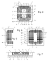
- the figure 2 represents, in top view, a front face of the transmitter in a first embodiment.
- the transmitter is rectangular, preferably in the form of a square of 5 cm x 5 cm, which corresponds to a European electrical standard. It comprises a transparent or translucent plastic cover 10 covering and protecting a photovoltaic element 7 whose sensitive surface is oriented towards the outside of the transmitter, and directly placed in contact with the cover.
- the cover may comprise a network of micro-lenses capable of focusing the light rays on the active parts of the sensitive surface.
- the lid has undergone anti-scratch and / or antifouling treatment on its outer face, flat. The presence of microlenses or other periodic pattern on the underside of the lid partially obscures fingerprints.
- the lid supports a functional component such as the control keyboard 5 in its central part.
- This keyboard includes two control keys, through the cover and activating contacts placed under the cover, as detailed below in connection with the figure 6 .
- the photovoltaic element comprises a positive pole 7a and a negative pole 7b connected to the supply circuit by a first connection 9a and a second connection 9b of the electrical connection means.
- the photovoltaic element has a flat ring shape, surrounding the functional component.
- the photovoltaic element is a single set of photovoltaic cells deployed non-linearly around the functional component.
- the photovoltaic element surrounds the functional component.
- the surface on which the photovoltaic element is supported is traversed by at least a portion of the functional component.
- the photovoltaic element can surround only partially the functional component, that is to say that the angle ⁇ under which the photovoltaic element is seen from the intersection of a central axis 111 of the functional element with the surface on which the functional element is or is supported is greater than 270 °, or even greater than 300 °, or even greater than 330 °.
- the photovoltaic element comprises a plurality of adjacent elements placed in series and having pairs of polarities alternating in the radial direction.
- the respective polarities of the elements are represented by arrows.
- the negative pole 7b is connected to a first adjacent element 71 of centripetal polarity, adjacent to a second adjacent element 72 of centrifugal polarity.
- the second adjacent element is itself adjacent to a third adjacent element 73 of centripetal polarity.
- the third adjacent element is itself adjacent to a fourth adjacent element 74 of centrifugal polarity.
- the fourth adjacent element is itself adjacent to a fifth adjacent element 75 of centripetal polarity.
- the fifth adjacent element is itself adjacent to a sixth adjacent element 76 of centrifugal polarity.
- the sixth adjacent element is itself adjacent to a seventh adjacent element 77 of centripetal polarity.
- the seventh adjacent element is itself adjacent to an eighth adjacent element 78 of centrifugal polarity.
- This eighth adjacent element is adjacent to the first adjacent element.
- a complete flat ring is thus formed around the functional component.
- the adjacent elements occupy as much surface as possible on the inner part of the cover left free by the functional component, parallel to the main plane of the cover.
- the areas of the adjacent elements are equal to each other so as to balance the operation of all the adjacent elements for a given common illumination.
- An adjacent element comprises an inner electrode and an outer electrode respectively disposed on an inner edge and a peripheral edge of the ring.
- Two internal electrodes may be connected for two adjacent adjacent elements, either forming an internal electrode (relative to the annular photovoltaic element), or by galvanic connection of two internal electrodes (relative to the annular photovoltaic element) separated .
- a first internal electrode 712 is common to adjacent elements 71-72
- a second internal electrode 734 is common to adjacent elements 73-74
- a third internal electrode 756 is common to adjacent elements 75-76
- a fourth internal electrode 778 is common to adjacent elements 77-78.
- two external electrodes may be connected for two adjacent adjacent elements, either forming an external electrode (relative to the annular photovoltaic element), or by galvanic connection of two external electrodes (relative to the photovoltaic element of shape annular) separated.
- a first outer electrode 723 is common to adjacent elements 72-73
- a second outer electrode 745 is common to adjacent elements 74-75
- a third outer electrode 767 is common to adjacent elements 76-77.
- a first adjacent element between a second adjacent element and a third adjacent element, is connected to the first adjacent element by connecting each external electrode and is connected to the third adjacent element by connecting each internal electrode.
- the figure 3 represents, in top view, a first variant, applied to the first embodiment.
- a photovoltaic element 7 'of poles 7'a, 7'b comprises a partially open ring, for example due to special constraints on the lid, but it surrounds as much as possible the functional component.
- the poles are located on internal electrodes.
- the functional component surrounded by the open ring is for example the sensor 6 or the antenna 3.
- the functional component is a small display screen.
- the figure 4 represents, in top view, a front face of the transmitter in a second embodiment.
- the second embodiment differs from the first embodiment by a different choice of the location of the poles and the direction of the polarizations and by the fact that the particular adjacent elements 70 * and 79 * have an area double that of the other adjacent elements. .
- a photovoltaic element 7 * according to this second mode comprises a positive pole 7a * and a negative pole 7b * located on opposite external electrodes, on either side of the functional element.
- the reference 70 * designating the set of adjacent elements 71 * and 78 *
- the reference 79 * designating the set of adjacent elements 74 * and 75 *.
- These two sets therefore constitute particular adjacent elements, each connected to one pole and whose area is double that of the adjacent elements.
- the negative pole is connected to an external electrode 745 * disposed at the periphery of the ring on the particular adjacent element 79 *
- the positive pole is connected to an external electrode 781 * disposed at the periphery of the ring, on the particular adjacent element 70 *.
- the two internal electrodes 712 * and 778 * may form only one electrode not connected to other adjacent elements, and likewise the two electrodes 734 * and 756 * may form a single electrode, not connected. to other adjacent elements.
- the photovoltaic element therefore contains two parallel paths, each path comprising the series connection of four elements, the end elements of which combine to form particular adjacent elements, the unconnected electrodes of the elements. particular adjacent elements constituting supply poles of the device.
- the figure 5 represents, in top view, a second variant, applicable to both embodiments. It is important that the areas of the adjacent elements be equal, but the shape of the adjacent elements may be arbitrary, provided that the electrical resistance of the elements, seen between electrodes, is equal. It may be advantageous to nest the adjacent elements so as to balance the photovoltaic behaviors.
- a herringbone interweaving allows to distribute on several adjacent elements a possible inhomogeneity in the illumination.
- the figure 5 gives an example of nesting, partially taking the figure 2 and assigning a double asterisk to equivalent references.
- radial (e) is meant a direction through an inner edge and a peripheral edge of the ring.
- the figure 6 partially shows, in top view, a front face of the transmitter in a third embodiment.
- the third embodiment differs from the first two modes in that adjacent elements have the same direction of polarities, one pole of a first adjacent element being close to an opposite pole of a second adjacent element.
- the adjacent elements are separated only by electrodes for directly connecting adjacent poles of adjacent elements.
- the photovoltaic element of the third embodiment contains two channels in parallel, each channel comprising putting in series four adjacent elements, the channels being located on either side of a functional component. 5 ***.
- the surface of the different single adjacent elements is equal.
- the extremes of each lane are connected to adjacent elements intermediates whose surface is double that of single adjacent elements.
- the single adjacent element 73 *** is connected to a first intermediate adjacent element 72 *** while the single adjacent element 76 *** is connected to the intermediate adjacent element 77 ***.
- the single adjacent elements 79 *** at the ends of the second path are connected to the first intermediate intermediate element 72 *** and the second intermediate adjacent element 77 ***.
- the first intermediate adjacent element 72 *** is itself connected to a first particular adjacent element 71 ***, also twice as large as that of the single adjacent elements, and to an unconnected electrode 7b *** constituting a first pole supply of the device.
- the second intermediate adjacent element 77 *** is itself connected to a second particular adjacent element 78 ***, also twice as large as that of the single adjacent elements, and to an unconnected electrode 7a *** constituting a second pole supply of the device.
- the figure 7 represents, according to a section A1A2, the radiofrequency transmitter 1 installed in a wall frame 11 fixed on a wall 100.
- the plane of the wall is parallel to the main plane P of the cover 10.
- the cover has side edges supporting a printed circuit 12 also parallel to the main plane of the cover.
- the lid is made of electrically insulating material.
- the control keyboard 5 comprises a key 5a traversing the keyboard and activating a switch 5b when it is depressed.
- the switch is disposed on a printed circuit 12, on which are also arranged the control unit 4, the radiofrequency unit 2 and the supply circuit 8.
- the adjacent elements 77 and 72 are arranged on the inner surface of the cover, parallel to the plane main P.
- the connection means 9 (appearing in dashed line) connects the entire photovoltaic element to the power supply circuit via the printed circuit.
- the ring formed by the photovoltaic element is not symmetrical, but the invention is all the easier to implement because a symmetrical structure is used. The best performances are obtained for a complete ring.
- the photovoltaic material is preferably of organic type.
- the deposits of the photovoltaic material and the conductive electrodes are preferably made by an inkjet technique.
- unconnected electrode is meant “not connected to an adjacent element”.
- At least substantially parallel means “parallel” or “substantially parallel”.
- the invention also applies to a device of nomadic type.
- the invention allows in particular the use of the remote control device under low light.
- a photovoltaic depot being conductive, it presents a screen for the electromagnetic waves emitted by the transmitter 2.
- a final advantage of the invention is to maintain a relatively central non-conductive zone over the entire surface occupied by the functional component and to avoid degradation of the performance of this emitter due to the photovoltaic element.
- the two geometric shapes or elements are complementary or substantially complementary. These shapes are preferably limited to wired shapes on a surface, particularly to two-dimensional shapes on the main plane of the lid or to projections of shapes on the main plane of the lid.
- the set of an inner edge of a portion is complementary or substantially complementary to the set of an outer edge from the other party. It is necessary and sufficient that one part has a concavity vis-à-vis a convexity of the other part and that these concavity and convexity are complementary or substantially complementary.
- two straight segments can not be considered as two nested geometric shapes.
Landscapes
- Engineering & Computer Science (AREA)
- Computer Networks & Wireless Communication (AREA)
- Physics & Mathematics (AREA)
- General Physics & Mathematics (AREA)
- Photovoltaic Devices (AREA)
- Selective Calling Equipment (AREA)
Applications Claiming Priority (1)
| Application Number | Priority Date | Filing Date | Title |
|---|---|---|---|
| FR0957780A FR2952229B1 (fr) | 2009-11-04 | 2009-11-04 | Dispositif de commande et/ou d'information a distance de l'etat de produits de type domotique, comprenant un panneau photovoltaique annulaire |
Publications (3)
| Publication Number | Publication Date |
|---|---|
| EP2320402A2 true EP2320402A2 (de) | 2011-05-11 |
| EP2320402A3 EP2320402A3 (de) | 2012-09-12 |
| EP2320402B1 EP2320402B1 (de) | 2017-08-30 |
Family
ID=42735698
Family Applications (1)
| Application Number | Title | Priority Date | Filing Date |
|---|---|---|---|
| EP10189835.1A Active EP2320402B1 (de) | 2009-11-04 | 2010-11-03 | Vorrichtung zur Fernsteuerung und/oder Informationsabfrage von Haushaltsgeräten mit einem ringförmigen Photovoltaikpanel |
Country Status (2)
| Country | Link |
|---|---|
| EP (1) | EP2320402B1 (de) |
| FR (1) | FR2952229B1 (de) |
Cited By (2)
| Publication number | Priority date | Publication date | Assignee | Title |
|---|---|---|---|---|
| CN103728908A (zh) * | 2014-01-21 | 2014-04-16 | 董乐山 | 一种家居控制开关 |
| EP2781680A3 (de) * | 2013-03-19 | 2014-10-08 | Brose Fahrzeugteile GmbH & Co. KG, Coburg | Vormontierte Baueinheit einer Schließvorrichtung eines Gebäudes |
Families Citing this family (1)
| Publication number | Priority date | Publication date | Assignee | Title |
|---|---|---|---|---|
| FR3067518B1 (fr) * | 2017-06-08 | 2020-03-13 | Somfy Activites Sa | Module photovoltaique integrant une antenne et dispositif domotique associe |
Citations (3)
| Publication number | Priority date | Publication date | Assignee | Title |
|---|---|---|---|---|
| FR2606912A1 (fr) | 1986-11-14 | 1988-05-20 | Pierron Sa | Dispositif formant emetteur a cellule photovoltaique |
| JPH089469B2 (ja) | 1989-06-28 | 1996-01-31 | 株式会社日立ビルシステムサービス | 乗場出入口装置の取付方法 |
| US20060157105A1 (en) | 2005-01-14 | 2006-07-20 | Semiconductor Energy Laboratory Co., Ltd. | Solar cell and semiconductor device, and manufacturing method thereof |
Family Cites Families (2)
| Publication number | Priority date | Publication date | Assignee | Title |
|---|---|---|---|---|
| EP0973139A1 (de) * | 1998-07-14 | 2000-01-19 | Eun Sook Suk | Fernbedienung für elektronisches Gerät |
| ITVA20030018A1 (it) * | 2003-06-05 | 2004-12-06 | Sergio Piacentini | Sistema elettronico di comando per impianti elettrici basato su onde radio. |
-
2009
- 2009-11-04 FR FR0957780A patent/FR2952229B1/fr active Active
-
2010
- 2010-11-03 EP EP10189835.1A patent/EP2320402B1/de active Active
Patent Citations (3)
| Publication number | Priority date | Publication date | Assignee | Title |
|---|---|---|---|---|
| FR2606912A1 (fr) | 1986-11-14 | 1988-05-20 | Pierron Sa | Dispositif formant emetteur a cellule photovoltaique |
| JPH089469B2 (ja) | 1989-06-28 | 1996-01-31 | 株式会社日立ビルシステムサービス | 乗場出入口装置の取付方法 |
| US20060157105A1 (en) | 2005-01-14 | 2006-07-20 | Semiconductor Energy Laboratory Co., Ltd. | Solar cell and semiconductor device, and manufacturing method thereof |
Cited By (2)
| Publication number | Priority date | Publication date | Assignee | Title |
|---|---|---|---|---|
| EP2781680A3 (de) * | 2013-03-19 | 2014-10-08 | Brose Fahrzeugteile GmbH & Co. KG, Coburg | Vormontierte Baueinheit einer Schließvorrichtung eines Gebäudes |
| CN103728908A (zh) * | 2014-01-21 | 2014-04-16 | 董乐山 | 一种家居控制开关 |
Also Published As
| Publication number | Publication date |
|---|---|
| FR2952229A1 (fr) | 2011-05-06 |
| FR2952229B1 (fr) | 2011-12-09 |
| EP2320402A3 (de) | 2012-09-12 |
| EP2320402B1 (de) | 2017-08-30 |
Similar Documents
| Publication | Publication Date | Title |
|---|---|---|
| EP3729332B1 (de) | Biometrische abbildungsvorrichtung und verfahren zur herstellung der biometrischen abbildungsvorrichtung | |
| EP2320402B1 (de) | Vorrichtung zur Fernsteuerung und/oder Informationsabfrage von Haushaltsgeräten mit einem ringförmigen Photovoltaikpanel | |
| CH663868A5 (fr) | Unite combinee d'interrupteur capacitif et son reseau. | |
| FR2914785A1 (fr) | Revetement de toiture photovoltaique | |
| WO2005071760A8 (en) | Solar panel | |
| EP3210162A1 (de) | Vorrichtung zur erfassung digitaler fingerabdrücke | |
| EP2823374B1 (de) | Elektronisches system mit einem standby-modus ohne stromverbrauch | |
| EP3721383B1 (de) | Omnidirektionaler identifizierungssensor für eine tief vergrabene nichtmetallische polymerröhre | |
| CH717849B1 (fr) | Dispositif de chauffage d'un bâtiment. | |
| BE1026104B1 (fr) | Luminaire connecté | |
| EP3190619A1 (de) | Fotodetektorvorrichtung und zugehörige verfahren | |
| EP2315223A1 (de) | Flexible Schutzhülle für eine Fernbedienung | |
| EP2171826A2 (de) | Verfahren und parametrisierbare einrichtung zum verteilen und verwalten von strom | |
| EP3339981B1 (de) | Armbanduhr, die mit einem thermoelektrischen druckknopf ausgestattet ist | |
| EP1313059B1 (de) | Bestandteil zur Berührungsdetektion, Verfahren unter Verwendung eines solchen Bestandteiles zur Berührungsdetektion und Gerät, wobei ein solcher Bestandteil eingebaut ist | |
| EP3652769B1 (de) | Elektrische ausrüstung und damit verbundenes zusätzliches funktionales modul | |
| EP3090115B1 (de) | Fenster für ein gebäude | |
| EP3652830A1 (de) | Elektrische einheit und zugehöriges zusätzliches funktionsmodul | |
| WO2016016519A1 (fr) | Module photoactif pluriponctionnel intégré dans un écran d'un appareil électronique et son organe de gestion | |
| FR2948488A1 (fr) | Transmetteur domotique radiofrequences autonome | |
| EP3214237B1 (de) | Steuerverfahren mindestens einer schwimmbadausstattung in abhängigkeit von der konfiguration eines abdeckelements und vorrichtungen hierfür | |
| EP3001499B1 (de) | Antennensystem, das als optisch quasi-transparent bezeichnet wird | |
| TW200725876A (en) | Image sensor and fabricating method thereof | |
| EP3472868A1 (de) | Solarpaneel und verfahren zur erhöhung der sicherheit und der zuverlässigkeit eines solarpaneels | |
| FR3003048A1 (fr) | Bouton sensitif a antenne capacitive. |
Legal Events
| Date | Code | Title | Description |
|---|---|---|---|
| PUAI | Public reference made under article 153(3) epc to a published international application that has entered the european phase |
Free format text: ORIGINAL CODE: 0009012 |
|
| AK | Designated contracting states |
Kind code of ref document: A2 Designated state(s): AL AT BE BG CH CY CZ DE DK EE ES FI FR GB GR HR HU IE IS IT LI LT LU LV MC MK MT NL NO PL PT RO RS SE SI SK SM TR |
|
| AX | Request for extension of the european patent |
Extension state: BA ME |
|
| PUAL | Search report despatched |
Free format text: ORIGINAL CODE: 0009013 |
|
| AK | Designated contracting states |
Kind code of ref document: A3 Designated state(s): AL AT BE BG CH CY CZ DE DK EE ES FI FR GB GR HR HU IE IS IT LI LT LU LV MC MK MT NL NO PL PT RO RS SE SI SK SM TR |
|
| AX | Request for extension of the european patent |
Extension state: BA ME |
|
| RIC1 | Information provided on ipc code assigned before grant |
Ipc: H02J 7/35 20060101ALI20120807BHEP Ipc: G08C 17/02 20060101AFI20120807BHEP |
|
| 17P | Request for examination filed |
Effective date: 20130312 |
|
| GRAP | Despatch of communication of intention to grant a patent |
Free format text: ORIGINAL CODE: EPIDOSNIGR1 |
|
| RIC1 | Information provided on ipc code assigned before grant |
Ipc: H02J 7/35 20060101ALI20170209BHEP Ipc: G08C 17/02 20060101AFI20170209BHEP Ipc: H01L 31/05 20140101ALI20170209BHEP |
|
| INTG | Intention to grant announced |
Effective date: 20170222 |
|
| RIN1 | Information on inventor provided before grant (corrected) |
Inventor name: DE BETTIGNIES, REMI Inventor name: GERINIERE, PIERRE Inventor name: GUILLEREZ, STEPHANE Inventor name: ROUSSEAU, FABIEN |
|
| GRAS | Grant fee paid |
Free format text: ORIGINAL CODE: EPIDOSNIGR3 |
|
| GRAA | (expected) grant |
Free format text: ORIGINAL CODE: 0009210 |
|
| AK | Designated contracting states |
Kind code of ref document: B1 Designated state(s): AL AT BE BG CH CY CZ DE DK EE ES FI FR GB GR HR HU IE IS IT LI LT LU LV MC MK MT NL NO PL PT RO RS SE SI SK SM TR |
|
| REG | Reference to a national code |
Ref country code: GB Ref legal event code: FG4D Free format text: NOT ENGLISH |
|
| REG | Reference to a national code |
Ref country code: CH Ref legal event code: EP |
|
| REG | Reference to a national code |
Ref country code: AT Ref legal event code: REF Ref document number: 924278 Country of ref document: AT Kind code of ref document: T Effective date: 20170915 |
|
| REG | Reference to a national code |
Ref country code: IE Ref legal event code: FG4D Free format text: LANGUAGE OF EP DOCUMENT: FRENCH |
|
| REG | Reference to a national code |
Ref country code: DE Ref legal event code: R096 Ref document number: 602010044785 Country of ref document: DE |
|
| RAP2 | Party data changed (patent owner data changed or rights of a patent transferred) |
Owner name: SOMFY ACTIVITES SA |
|
| REG | Reference to a national code |
Ref country code: FR Ref legal event code: PLFP Year of fee payment: 8 |
|
| REG | Reference to a national code |
Ref country code: DE Ref legal event code: R081 Ref document number: 602010044785 Country of ref document: DE Owner name: SOMFY ACTIVITES SA, FR Free format text: FORMER OWNER: SOMFY SAS, CLUSES, FR |
|
| REG | Reference to a national code |
Ref country code: NL Ref legal event code: MP Effective date: 20170830 |
|
| REG | Reference to a national code |
Ref country code: LT Ref legal event code: MG4D |
|
| REG | Reference to a national code |
Ref country code: AT Ref legal event code: MK05 Ref document number: 924278 Country of ref document: AT Kind code of ref document: T Effective date: 20170830 |
|
| PG25 | Lapsed in a contracting state [announced via postgrant information from national office to epo] |
Ref country code: LT Free format text: LAPSE BECAUSE OF FAILURE TO SUBMIT A TRANSLATION OF THE DESCRIPTION OR TO PAY THE FEE WITHIN THE PRESCRIBED TIME-LIMIT Effective date: 20170830 Ref country code: FI Free format text: LAPSE BECAUSE OF FAILURE TO SUBMIT A TRANSLATION OF THE DESCRIPTION OR TO PAY THE FEE WITHIN THE PRESCRIBED TIME-LIMIT Effective date: 20170830 Ref country code: AT Free format text: LAPSE BECAUSE OF FAILURE TO SUBMIT A TRANSLATION OF THE DESCRIPTION OR TO PAY THE FEE WITHIN THE PRESCRIBED TIME-LIMIT Effective date: 20170830 Ref country code: HR Free format text: LAPSE BECAUSE OF FAILURE TO SUBMIT A TRANSLATION OF THE DESCRIPTION OR TO PAY THE FEE WITHIN THE PRESCRIBED TIME-LIMIT Effective date: 20170830 Ref country code: SE Free format text: LAPSE BECAUSE OF FAILURE TO SUBMIT A TRANSLATION OF THE DESCRIPTION OR TO PAY THE FEE WITHIN THE PRESCRIBED TIME-LIMIT Effective date: 20170830 Ref country code: NO Free format text: LAPSE BECAUSE OF FAILURE TO SUBMIT A TRANSLATION OF THE DESCRIPTION OR TO PAY THE FEE WITHIN THE PRESCRIBED TIME-LIMIT Effective date: 20171130 |
|
| PG25 | Lapsed in a contracting state [announced via postgrant information from national office to epo] |
Ref country code: GR Free format text: LAPSE BECAUSE OF FAILURE TO SUBMIT A TRANSLATION OF THE DESCRIPTION OR TO PAY THE FEE WITHIN THE PRESCRIBED TIME-LIMIT Effective date: 20171201 Ref country code: ES Free format text: LAPSE BECAUSE OF FAILURE TO SUBMIT A TRANSLATION OF THE DESCRIPTION OR TO PAY THE FEE WITHIN THE PRESCRIBED TIME-LIMIT Effective date: 20170830 Ref country code: LV Free format text: LAPSE BECAUSE OF FAILURE TO SUBMIT A TRANSLATION OF THE DESCRIPTION OR TO PAY THE FEE WITHIN THE PRESCRIBED TIME-LIMIT Effective date: 20170830 Ref country code: BG Free format text: LAPSE BECAUSE OF FAILURE TO SUBMIT A TRANSLATION OF THE DESCRIPTION OR TO PAY THE FEE WITHIN THE PRESCRIBED TIME-LIMIT Effective date: 20171130 Ref country code: IS Free format text: LAPSE BECAUSE OF FAILURE TO SUBMIT A TRANSLATION OF THE DESCRIPTION OR TO PAY THE FEE WITHIN THE PRESCRIBED TIME-LIMIT Effective date: 20171230 Ref country code: RS Free format text: LAPSE BECAUSE OF FAILURE TO SUBMIT A TRANSLATION OF THE DESCRIPTION OR TO PAY THE FEE WITHIN THE PRESCRIBED TIME-LIMIT Effective date: 20170830 |
|
| PG25 | Lapsed in a contracting state [announced via postgrant information from national office to epo] |
Ref country code: NL Free format text: LAPSE BECAUSE OF FAILURE TO SUBMIT A TRANSLATION OF THE DESCRIPTION OR TO PAY THE FEE WITHIN THE PRESCRIBED TIME-LIMIT Effective date: 20170830 |
|
| PG25 | Lapsed in a contracting state [announced via postgrant information from national office to epo] |
Ref country code: CZ Free format text: LAPSE BECAUSE OF FAILURE TO SUBMIT A TRANSLATION OF THE DESCRIPTION OR TO PAY THE FEE WITHIN THE PRESCRIBED TIME-LIMIT Effective date: 20170830 Ref country code: PL Free format text: LAPSE BECAUSE OF FAILURE TO SUBMIT A TRANSLATION OF THE DESCRIPTION OR TO PAY THE FEE WITHIN THE PRESCRIBED TIME-LIMIT Effective date: 20170830 Ref country code: RO Free format text: LAPSE BECAUSE OF FAILURE TO SUBMIT A TRANSLATION OF THE DESCRIPTION OR TO PAY THE FEE WITHIN THE PRESCRIBED TIME-LIMIT Effective date: 20170830 Ref country code: DK Free format text: LAPSE BECAUSE OF FAILURE TO SUBMIT A TRANSLATION OF THE DESCRIPTION OR TO PAY THE FEE WITHIN THE PRESCRIBED TIME-LIMIT Effective date: 20170830 |
|
| PG25 | Lapsed in a contracting state [announced via postgrant information from national office to epo] |
Ref country code: EE Free format text: LAPSE BECAUSE OF FAILURE TO SUBMIT A TRANSLATION OF THE DESCRIPTION OR TO PAY THE FEE WITHIN THE PRESCRIBED TIME-LIMIT Effective date: 20170830 Ref country code: SK Free format text: LAPSE BECAUSE OF FAILURE TO SUBMIT A TRANSLATION OF THE DESCRIPTION OR TO PAY THE FEE WITHIN THE PRESCRIBED TIME-LIMIT Effective date: 20170830 Ref country code: IT Free format text: LAPSE BECAUSE OF FAILURE TO SUBMIT A TRANSLATION OF THE DESCRIPTION OR TO PAY THE FEE WITHIN THE PRESCRIBED TIME-LIMIT Effective date: 20170830 Ref country code: SM Free format text: LAPSE BECAUSE OF FAILURE TO SUBMIT A TRANSLATION OF THE DESCRIPTION OR TO PAY THE FEE WITHIN THE PRESCRIBED TIME-LIMIT Effective date: 20170830 |
|
| REG | Reference to a national code |
Ref country code: DE Ref legal event code: R097 Ref document number: 602010044785 Country of ref document: DE |
|
| PG25 | Lapsed in a contracting state [announced via postgrant information from national office to epo] |
Ref country code: MC Free format text: LAPSE BECAUSE OF FAILURE TO SUBMIT A TRANSLATION OF THE DESCRIPTION OR TO PAY THE FEE WITHIN THE PRESCRIBED TIME-LIMIT Effective date: 20170830 |
|
| PLBE | No opposition filed within time limit |
Free format text: ORIGINAL CODE: 0009261 |
|
| STAA | Information on the status of an ep patent application or granted ep patent |
Free format text: STATUS: NO OPPOSITION FILED WITHIN TIME LIMIT |
|
| GBPC | Gb: european patent ceased through non-payment of renewal fee |
Effective date: 20171130 |
|
| PG25 | Lapsed in a contracting state [announced via postgrant information from national office to epo] |
Ref country code: LI Free format text: LAPSE BECAUSE OF NON-PAYMENT OF DUE FEES Effective date: 20171130 Ref country code: CH Free format text: LAPSE BECAUSE OF NON-PAYMENT OF DUE FEES Effective date: 20171130 |
|
| 26N | No opposition filed |
Effective date: 20180531 |
|
| PG25 | Lapsed in a contracting state [announced via postgrant information from national office to epo] |
Ref country code: SI Free format text: LAPSE BECAUSE OF FAILURE TO SUBMIT A TRANSLATION OF THE DESCRIPTION OR TO PAY THE FEE WITHIN THE PRESCRIBED TIME-LIMIT Effective date: 20170830 Ref country code: LU Free format text: LAPSE BECAUSE OF NON-PAYMENT OF DUE FEES Effective date: 20171103 |
|
| REG | Reference to a national code |
Ref country code: BE Ref legal event code: MM Effective date: 20171130 |
|
| REG | Reference to a national code |
Ref country code: IE Ref legal event code: MM4A |
|
| PG25 | Lapsed in a contracting state [announced via postgrant information from national office to epo] |
Ref country code: MT Free format text: LAPSE BECAUSE OF FAILURE TO SUBMIT A TRANSLATION OF THE DESCRIPTION OR TO PAY THE FEE WITHIN THE PRESCRIBED TIME-LIMIT Effective date: 20170830 |
|
| PG25 | Lapsed in a contracting state [announced via postgrant information from national office to epo] |
Ref country code: IE Free format text: LAPSE BECAUSE OF NON-PAYMENT OF DUE FEES Effective date: 20171103 |
|
| PG25 | Lapsed in a contracting state [announced via postgrant information from national office to epo] |
Ref country code: BE Free format text: LAPSE BECAUSE OF NON-PAYMENT OF DUE FEES Effective date: 20171130 Ref country code: GB Free format text: LAPSE BECAUSE OF NON-PAYMENT OF DUE FEES Effective date: 20171130 |
|
| PG25 | Lapsed in a contracting state [announced via postgrant information from national office to epo] |
Ref country code: HU Free format text: LAPSE BECAUSE OF FAILURE TO SUBMIT A TRANSLATION OF THE DESCRIPTION OR TO PAY THE FEE WITHIN THE PRESCRIBED TIME-LIMIT; INVALID AB INITIO Effective date: 20101103 |
|
| PG25 | Lapsed in a contracting state [announced via postgrant information from national office to epo] |
Ref country code: CY Free format text: LAPSE BECAUSE OF NON-PAYMENT OF DUE FEES Effective date: 20170830 |
|
| PG25 | Lapsed in a contracting state [announced via postgrant information from national office to epo] |
Ref country code: MK Free format text: LAPSE BECAUSE OF FAILURE TO SUBMIT A TRANSLATION OF THE DESCRIPTION OR TO PAY THE FEE WITHIN THE PRESCRIBED TIME-LIMIT Effective date: 20170830 |
|
| PG25 | Lapsed in a contracting state [announced via postgrant information from national office to epo] |
Ref country code: TR Free format text: LAPSE BECAUSE OF FAILURE TO SUBMIT A TRANSLATION OF THE DESCRIPTION OR TO PAY THE FEE WITHIN THE PRESCRIBED TIME-LIMIT Effective date: 20170830 |
|
| PG25 | Lapsed in a contracting state [announced via postgrant information from national office to epo] |
Ref country code: PT Free format text: LAPSE BECAUSE OF FAILURE TO SUBMIT A TRANSLATION OF THE DESCRIPTION OR TO PAY THE FEE WITHIN THE PRESCRIBED TIME-LIMIT Effective date: 20170830 |
|
| PG25 | Lapsed in a contracting state [announced via postgrant information from national office to epo] |
Ref country code: AL Free format text: LAPSE BECAUSE OF FAILURE TO SUBMIT A TRANSLATION OF THE DESCRIPTION OR TO PAY THE FEE WITHIN THE PRESCRIBED TIME-LIMIT Effective date: 20170830 |
|
| PGFP | Annual fee paid to national office [announced via postgrant information from national office to epo] |
Ref country code: FR Payment date: 20250929 Year of fee payment: 16 |
|
| PGFP | Annual fee paid to national office [announced via postgrant information from national office to epo] |
Ref country code: DE Payment date: 20251117 Year of fee payment: 16 |