EP2320294A1 - Elektronische Anschlussvorrichtung für eine Raumtemperaturregelanlage zum Regeln der Raumtemperatur in warmwasserbeheizten Räumen - Google Patents
Elektronische Anschlussvorrichtung für eine Raumtemperaturregelanlage zum Regeln der Raumtemperatur in warmwasserbeheizten Räumen Download PDFInfo
- Publication number
- EP2320294A1 EP2320294A1 EP10187351A EP10187351A EP2320294A1 EP 2320294 A1 EP2320294 A1 EP 2320294A1 EP 10187351 A EP10187351 A EP 10187351A EP 10187351 A EP10187351 A EP 10187351A EP 2320294 A1 EP2320294 A1 EP 2320294A1
- Authority
- EP
- European Patent Office
- Prior art keywords
- module
- connection
- power supply
- operated
- room temperature
- Prior art date
- Legal status (The legal status is an assumption and is not a legal conclusion. Google has not performed a legal analysis and makes no representation as to the accuracy of the status listed.)
- Granted
Links
- XLYOFNOQVPJJNP-UHFFFAOYSA-N water Substances O XLYOFNOQVPJJNP-UHFFFAOYSA-N 0.000 title claims abstract description 11
- 230000001105 regulatory effect Effects 0.000 title claims 2
- 238000000926 separation method Methods 0.000 claims description 4
- 230000001276 controlling effect Effects 0.000 claims 1
- 241001136792 Alle Species 0.000 description 2
- 238000010276 construction Methods 0.000 description 1
- 238000010438 heat treatment Methods 0.000 description 1
- 239000008236 heating water Substances 0.000 description 1
Images
Classifications
-
- G—PHYSICS
- G05—CONTROLLING; REGULATING
- G05D—SYSTEMS FOR CONTROLLING OR REGULATING NON-ELECTRIC VARIABLES
- G05D23/00—Control of temperature
- G05D23/19—Control of temperature characterised by the use of electric means
- G05D23/1927—Control of temperature characterised by the use of electric means using a plurality of sensors
- G05D23/193—Control of temperature characterised by the use of electric means using a plurality of sensors sensing the temperaure in different places in thermal relationship with one or more spaces
- G05D23/1932—Control of temperature characterised by the use of electric means using a plurality of sensors sensing the temperaure in different places in thermal relationship with one or more spaces to control the temperature of a plurality of spaces
- G05D23/1934—Control of temperature characterised by the use of electric means using a plurality of sensors sensing the temperaure in different places in thermal relationship with one or more spaces to control the temperature of a plurality of spaces each space being provided with one sensor acting on one or more control means
Definitions
- the invention relates to an electronic connection device for a room temperature control system for controlling the room temperature in hot water heated rooms, with one or more control circuits for controlling one or more actuators of hot water valves based on the signals from one or more room temperature sensors and with a connectable to a mains voltage mains voltage line, to each Control circuit is connected to supply the line voltage operated actuators.
- the room temperature sensors which are also arranged in the living area, are operated with 230V mains voltage, which means a high contact protection, a danger for children and electrosmog.
- Another disadvantage is that the 230V voltage of each room temperature sensor for the operated with low voltage electronic control must be reduced to this extra voltage, which brings additional effort and heat losses.
- the invention is therefore based on the object to increase energy efficiency in a connection device of the type mentioned and at the same time to reduce the risk to a user.
- a central power supply is connected to the mains voltage line, which transforms the mains voltage to a lower low voltage, which is operated to each control circuit for supplying the low voltage electronic circuits of the control circuits - and possibly also for the supply of operated with the low voltage room temperature sensor - forwarded.
- the invention is based on the idea that the relatively power consuming actuators are connected to the mains voltage (e.g., 230V) while the sensitive electrical circuits as well as the room temperature sensors are operated at a substantially lower DC voltage (e.g., 5V).
- the connecting device according to the invention has a central power supply which is connected to the mains voltage and which transforms the mains voltage centrally to the low voltage for the electronic circuits and for the room temperature sensor.
- the provided for the control of the actuators connections are located on the mains voltage line, while the low-voltage line supplied to a circuit of the control circuits and on the other hand has the connections for supplying the corresponding room temperature sensor.
- the connecting device thus has the significant advantage that a separate power supply for each room temperature sensor is eliminated and the more energy-intensive actuators are connected directly to the non-transformed mains voltage.
- the room temperature sensors pose no danger to a user due to the low voltage, so that the room temperature sensor can also be used in places accessible to children in living rooms and wet rooms and can be safely used in bedrooms and living rooms, because of the DC low voltage no electrosmog is generated.
- the mains voltage side and the low voltage side are electrically isolated, e.g. galvanically separated by optocouplers or by means of relays.
- the central power supply is arranged in a power supply module, to which in turn one or more connection modules, which each have at least one control circuit, can be connected.
- the power supply module can either have only the central power supply and other central components, such as clock, pump logic or valve protection, or in addition already one or more control circuits.
- connection module extends in the power supply module, the power line and starting from the central power supply a low voltage line in each case to the output side module connection side of the power supply module to which a connection module with its input side module connection side can be connected.
- each connection module extending from electrical connection contacts on its input side module connection side, the power and low voltage lines and cables that are connected to central components of the power supply module (clock, pump logic, valve protection) to electrical connection contacts on its output side module connection side, so that each next connection module is connected to these lines.
- the connection modules are formed identically, wherein the input side module connection side of a connection module and the output side module connection side of another connection module are connected to each other and each module has a potential separation between the mains voltage operated side and operated with low voltage side.
- the invention also relates to a room temperature control system with a connecting device as described above, wherein one or more low-voltage-operated room temperature sensor and one or more actuated with mains voltage actuators are connected to each control circuit.
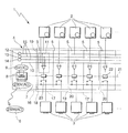
- the electronic room temperature control system 1 shown schematically in the single figure is used to control the room temperature in hot water heated rooms and includes several room temperature sensor 2, several actuators 3 of hot water valves and a connection device 4 for connecting the room temperature sensor 2 and the actuators 3.
- the connection device 4 has a plurality of control circuits. 5 on which actuate the actuators 3 based on the signals from one or more room temperature sensors 2, wherein for the sake of simplicity only one room temperature sensor 2 and one actuator 3 per control circuit 5 are shown.
- the connection device 4 has a mains voltage line 7 connected to a 230V (AC) mains voltage 6 , to which each control circuit 5 is connected to supply its actuator 3, which is operated with 230V mains voltage 6.
- a central power supply unit 8 is connected, which transforms the 230V (AC) mains voltage 6 to a lower low voltage (DC) 9, eg 5V (DC), via a low voltage line 10 to each control circuit 5 to supply their Low voltage operated electronic circuit 11 is forwarded.
- the room temperature sensors 2 are also operated with the extra-low voltage, eg 5V (DC), and are either also connected to the low voltage line 10 or have their own battery during radio operation.
- the connecting device 4 also has a clock 12, a pump logic 13 and a valve protection 14 , which are operated with the 5V (DC) -Kleintension 9 and are forwarded via control lines 15 to the circuits 11 of the control circuits 5 and to the room temperature sensor 2.
- each connection module 17 has two control circuits 5.
- connection modules 17 may be of identical construction, the output-side module connection side 20 of a connection module 17 and the input-side module connection side 19 of another connection module 17 being connectable to one another via electrical connection contacts (not shown).
- connection modules 17 extend from electrical connection contacts on the input side module connection side 19, the power and low voltage lines 7, 10 and the control lines 15 to electrical connection contacts on the output side module connection side 20.
- the voltage line 7 extends from the power supply module 16 through all connected connection modules 17 through to supply all actuators 3 with the 230V mains voltage 6.
- the low-voltage line 10 and the control lines 15 extend from the power supply module 16 through all the connected connection modules 17 to supply all the circuits 11 - possibly also the room temperature sensor 2 - with the 5V low voltage 9 and the control signals of the power supply module 16.
- Each module 16, 17 has between the 230V mains voltage 6 and the 5V low voltage 9 a galvanic potential separation 21 , which is formed by means of optocouplers or relays 22 .
Landscapes
- Engineering & Computer Science (AREA)
- Remote Sensing (AREA)
- Physics & Mathematics (AREA)
- General Physics & Mathematics (AREA)
- Automation & Control Theory (AREA)
- Air Conditioning Control Device (AREA)
- Heat-Pump Type And Storage Water Heaters (AREA)
- Steam Or Hot-Water Central Heating Systems (AREA)
Abstract
Description
- Die Erfindung betrifft eine elektronische Anschlussvorrichtung für eine Raumtemperaturregelanlage zum Regeln der Raumtemperatur in warmwasserbeheizten Räumen, mit einer oder mehreren Steuerschaltungen zum Ansteuern eines oder mehrerer Stellantriebe von Warmwasserventilen anhand der Signale von einem oder mehreren Raumtemperaturfühlern und mit einer an eine Netzspannung anschließbaren Netzspannungsleitung, an die jede Steuerschaltung zur Versorgung der mit Netzspannung betriebenen Stellantriebe angeschlossen ist.
- Eine Raumtemperaturregelanlage besteht im Allgemein aus folgenden drei Teilen:
- jeweils mindestens einem Raumtemperaturfühler pro Raum;
- jeweils mindestens einem Stellantrieb pro Raumtemperaturfühler, wobei der Stellantrieb beispielsweise an einem Warmwasserventil angebracht ist und den Warmwasserfluss steuert; und
- einem oder mehreren elektronischen Steuerschaltungen, die die Stellantriebe jeweils anhand der Signale von den Raumtemperaturfühlern ansteuern.
- Hierbei sind zwei verschiedene Ausführungen bekannt:
- 1. Alle oben genannten Komponenten der Raumtemperaturregelanlage werden mit der Netzspannung (d.h. mit 230V) betrieben;
- 2. Alle oben genannten Komponenten der Raumtemperaturregelanlage werden mit einer Kleinspannung (z.B. 24V) betrieben.
- Bei der ersten Ausführung ist von Nachteil, dass die auch im Wohnbereich angeordneten Raumtemperaturfühler mit 230V Netzspannung betrieben werden, was einen hohen Berührungsschutz, eine Gefahr für Kinder und Elektrosmog bedeutet. Ein weiterer Nachteil ist dabei, dass die 230V-Spannung jedes Raumtemperaturfühlers für die mit Kleinspannung betriebene elektronische Regelung auf diese Kleinspannung heruntergesetzt werden muss, was zusätzlichen Aufwand und Wärmeverluste mit sich bringt.
- Bei der zweiten Ausführung ist von Nachteil, dass ein großer und aufwendiger Transformator 230V/24V benötigt wird, da die Stellantriebe bei der niedrigen Spannung von 24V viel Strom verbrauchen.
- Der Erfindung liegt daher die Aufgabe zugrunde, bei einer Anschlussvorrichtung der eingangs genannten Art die Energieeffizienz zu erhöhen und gleichzeitig die Gefahren für einen Nutzer zu reduzieren.
- Diese Aufgabe wird erfindungsgemäß dadurch gelöst, dass an die Netzspannungsleitung ein zentrales Netzteil angeschlossen ist, das die Netzspannung auf eine niedrigere Kleinspannung transformiert, die an jede Steuerschaltung zur Versorgung der mit der Kleinspannung betriebenen elektronischen Schaltkreise der Steuerschaltungen - und ggf. auch zur Versorgung der mit der Kleinspannung betriebenen Raumtemperaturfühler - weitergeleitet ist.
- Die Erfindung basiert auf der Idee, dass die relativ viel Energie konsumierenden Stellantriebe an die Netzspannung (z.B. 230V) angeschlossen sind, während die empfindlichen elektrischen Schaltkreise sowie die Raumtemperaturfühler mit einer wesentlich niedrigeren Gleich- bzw. Kleinspannung (z.B. 5V) betrieben werden. Zu diesem Zweck weist die Anschlussvorrichtung erfindungsgemäß ein zentrales Netzteil auf, das an die Netzspannung angeschlossen wird und das die Netzspannung zentral auf die Kleinspannung für die elektronischen Schaltkreise und für die Raumtemperaturfühler transformiert. Die für die Ansteuerung der Stellantriebe vorgesehenen Anschlüsse liegen an der Netzspannungsleitung, während die Kleinspannungsleitung zum einen die Schaltkreise der Steuerschaltungen versorgt und zum anderen die Anschlüsse zur Versorgung der entsprechenden Raumtemperaturfühler aufweist. Die erfindungsgemäße Anschlussvorrichtung hat damit den wesentlichen Vorteil, dass ein eigenes Netzteil für jeden Raumtemperaturfühler entfällt und die energieintensiveren Stellantriebe direkt an die nicht transformierte Netzspannung angeschlossen werden. Neben der daraus resultierenden hohen Energieeffizienz der gesamten Regelanlage gehen von den Raumtemperaturfühlern aufgrund der Kleinspannung keine Gefahren für einen Nutzer aus, so dass die Raumtemperaturfühler auch an für Kinder zugänglichen Stellen in Wohnräumen und Nassräumen angebracht und bedenkenlos auch in Schlaf- und Wohnräumen verwendet werden können, da aufgrund der DC-Kleinspannung kein Elektrosmog entsteht.
- Vorzugsweise sind in der gesamten Anschlussvorrichtung die mit Netzspannung betriebene Seite und die mit Kleinspannung betriebene Seite durch eine Potentialtrennung, z.B. galvanisch mittels Optokopplern oder mittels Relais, voneinander getrennt.
- Bei einer besonders bevorzugten Ausführungsform der Erfindung ist das zentrale Netzteil in einem Netzteilmodul angeordnet, an das wiederum ein oder mehrere Anschlussmodule, welche jeweils mindestens eine Steuerschaltung aufweisen, anschließbar sind. Diese Ausführungsform ermöglicht eine modulare Bauweise und dadurch eine individuelle Erweiterung auf die gewünschte Anzahl von Steuerschaltungen. Das Netzteilmodul kann entweder nur das zentrale Netzteil und weitere zentrale Komponenten, wie z.B. Uhr, Pumpenlogik oder Ventilschutz, oder zusätzlich bereits eine oder mehrere Steuerschaltungen aufweisen.
- In einer vorteilhaften Weiterbildung dieser Ausführungsform erstrecken sich in dem Netzteilmodul die Netzspannungsleitung und ausgehend vom zentralen Netzteil eine Kleinspannungsleitung jeweils bis zu der ausgangsseitigen Modulanschlussseite des Netzteilmoduls, an die ein Anschlussmodul mit seiner eingangsseitigen Modulanschlussseite anschließbar ist. In jedem Anschlussmodul erstrecken sich ausgehend von elektrischen Anschlusskontakten an seiner eingangsseitigen Modulanschlussseite die Netz- und Kleinspannungsleitungen sowie Leitungen, die an zentrale Komponenten des Netzteilmoduls (Uhr, Pumpenlogik, Ventilschutz) angeschlossen sind, bis zu elektrischen Anschlusskontakten an seiner ausgangsseitigen Modulanschlussseite, damit auch das jeweils nächste Anschlussmodul an diese Leitungen angeschlossen ist. Vorzugsweise sind die Anschlussmodule identisch ausgebildet, wobei die eingangsseitige Modulanschlussseite eines Anschlussmoduls und die ausgangsseitige Modulanschlussseite eines anderen Anschlussmoduls aneinander anschließbar sind und jedes Modul eine Potentialtrennung zwischen der mit Netzspannung betriebenen Seite und der mit Kleinspannung betriebenen Seite aufweist.
- Die Erfindung betrifft auch eine Raumtemperaturregelanlage mit einer wie oben ausgebildeten Anschlussvorrichtung, wobei an jede Steuerschaltung ein oder mehrere mit Kleinspannung betriebene Raumtemperaturfühler sowie ein oder mehrere mit Netzspannung betriebene Stellantriebe angeschlossen sind.
- Weitere Vorteile der Erfindung ergeben sich aus der Beschreibung und der Zeichnung. Ebenso können die vorstehend genannten und die noch weiter ausgeführten Merkmale erfindungsgemäß jeweils einzeln für sich oder zu mehreren in beliebigen Kombinationen Verwendung finden. Die gezeigte und beschriebene Ausführungsform ist nicht als abschließende Aufzählung zu verstehen, sondern hat vielmehr beispielhaften Charakter für die Schilderung der Erfindung. Die Erfindung ist in einem Ausführungsbeispiel in der Zeichnung dargestellt und wird in der nachfolgenden Beschreibung näher erläutert.
- Die in der einzigen Figur schematisch gezeigte elektronische Raumtemperaturregelanlage 1 dient zum Regeln der Raumtemperatur in warmwasserbeheizten Räumen und umfasst mehrere Raumtemperaturfühler 2, mehrere Stellantriebe 3 von Warmwasserventilen sowie eine Anschlussvorrichtung 4 zum Anschließen der Raumtemperaturfühler 2 und der Stellantriebe 3. Die Anschlussvorrichtung 4 weist mehrere Steuerschaltungen 5 auf, welche die Stellantriebe 3 anhand der Signale von einem oder mehreren Raumtemperaturfühlern 2 ansteuern, wobei der Einfachheit halber jeweils nur ein Raumtemperaturfühler 2 und ein Stellantrieb 3 pro Steuerschaltung 5 gezeigt sind.
- Die Anschlussvorrichtung 4 weist eine an eine 230V(AC)-Netzspannung 6 angeschlossene Netzspannungsleitung 7 auf, an die jede Steuerschaltung 5 zur Versorgung ihres mit 230V-Netzspannung 6 betriebenen Stellantriebes 3 angeschlossen ist. Die Stellantriebe 3, die zum Steuern der Warmwasserzufuhr an den entsprechenden Heizungsventilen dienen, benötigen relativ viel elektrische Energie und werden daher von der Anschlussvorrichtung 4 zentral mit der 230V-Netzspannung 6 versorgt. An die Netzspannungsleitung 7 ist ein zentrales Netzteil 8 angeschlossen, das die 230V(AC)-Netzspannung 6 auf eine niedrigere Kleinspannung (Gleichspannung) 9, z.B. 5V(DC), transformiert, die über eine Kleinspannungsleitung 10 an jede Steuerschaltung 5 zur Versorgung ihres mit Kleinspannung betriebenen elektronischen Schaltkreises 11 weitergeleitet ist. Die Raumtemperaturfühler 2 werden ebenfalls mit der Kleinspannung, z.B. 5V (DC), betrieben und sind dazu entweder auch an die Kleinspannungsleitung 10 angeschlossen oder weisen bei Funkbetrieb eine eigene Batterie auf.
- Die Anschlussvorrichtung 4 weist außerdem noch eine Uhr 12, eine Pumpenlogik 13 und einen Ventilschutz 14 auf, die mit der 5V(DC)-Kleinspannung 9 betrieben werden und über Steuerleitungen 15 an die Schaltkreise 11 der Steuerschaltungen 5 und an die Raumtemperaturfühler 2 weitergeleitet sind.
- Das zentrale Netzteil 8, die Uhr 12, die Pumpenlogik 13 und der Ventilschutz 14 sind in einem Netzteilmodul 16 angeordnet, an das ein oder mehrere Anschlussmodule 17 anschließbar sind. Im gezeigten Ausführungsbeispiel weist jedes Anschlussmodul 17 zwei Steuerschaltungen 5 auf.
- In dem Netzteilmodul 16 erstrecken sich die Netz- und Kleinspannungsleitungen 7, 10 sowie die Steuerleitungen 15 jeweils bis zu elektrischen Anschlusskontakten (nicht gezeigt) an der ausgangsseitigen Modulanschlussseite 18 des Netzteilmoduls 16, an die das Anschlussmodul 17 mit seiner eingangsseitigen Modulanschlussseite 19 über elektrische Anschlusskontakte (nicht gezeigt) angeschlossen ist. Die Anschlussmodule 17 können identisch ausgebildet sein, wobei die ausgangsseitige Modulanschlussseite 20 eines Anschlussmoduls 17 und die eingangsseitige Modulanschlussseite 19 eines anderen Anschlussmoduls 17 über elektrische Anschlusskontakte (nicht gezeigt) aneinander anschließbar sind. In jedem Anschlussmodul 17 erstrecken sich ausgehend von elektrischen Anschlusskontakten an der eingangsseitigen Modulanschlussseite 19 die Netz- und Kleinspannungsleitungen 7, 10 sowie die Steuerleitungen 15 bis zu elektrischen Anschlusskontakten an der ausgangsseitigen Modulanschlussseite 20. Die Spannungsleitung 7 zieht sich ausgehend vom Netzteilmodul 16 durch alle angeschlossenen Anschlussmodule 17 durch, um alle Stellantriebe 3 mit der 230V-Netzspannung 6 zu versorgen. Die Kleinspannungsleitung 10 und die Steuerleitungen15 ziehen sich ausgehend vom Netzteilmodul 16 durch alle angeschlossenen Anschlussmodule 17 durch, um alle Schaltkreise 11 - ggf. auch die Raumtemperaturfühler 2 - mit der 5V-Kleinspannung 9 und mit den Steuersignalen des Netzteilmoduls 16 zu versorgen.
- Jedes Modul 16, 17 weist zwischen der 230V-Netzspannung 6 und der 5V-Kleinspannung 9 eine galvanische Potentialtrennung 21 auf, die mittels Optokopplern oder Relais 22 ausgebildet ist.
- Die Funktionsweise der Raumtemperaturregelanlage 1 ist wie folgt:
- Jeder Raumtemperaturfühler 2 misst die Raumtemperatur und vergleicht das Signal mit der für diesen Raum eingestellten Solltemperatur. Das Ergebnis wird per Draht oder Funk an den Schaltkreis 11 der zugehörigen Steuerschaltung 5 weitergeleitet, die abhängig vom Signal des Raumtemperaturfühlers 2 und unter Einbeziehung der Steuersignale von Uhr 12, Pumpenlogik 13 und Ventilschutz 14 den jeweiligen Stellantrieb 3 ansteuert. Das binäre 5V-Ausgangssignal des Schaltkreises 11 wird über den Optokoppler/Relais 22 als Steuersignal an einen Ein-Aus-Schalter 23 weitergegeben, der an die Netzspannungsleitung 7 angeschlossen ist und die 230V-Netzspannung an den Stellantrieb 3 schaltet, um so das Ventil für das Heizungswasser im entsprechenden Raum zu öffnen oder zu schließen.
Claims (12)
- Anschlussvorrichtung (4) für eine Raumtemperaturregelanlage (1) zum Regeln der Raumtemperatur in warmwasserbeheizten Räumen,mit einer oder mehreren Steuerschaltungen (5) zum Ansteuern eines oder mehrerer Stellantriebe (3) von Warmwasserventilen anhand der Signale von einem oder mehreren Raumtemperaturfühlern (2) undmit einer an eine Netzspannung (6) anschließbaren Netzspannungsleitung (7), an die jede Steuerschaltung (5) zur Versorgung der mit Netzspannung (6) betriebenen Stellantriebe (3) angeschlossen ist,dadurch gekennzeichnet,dass an die Netzspannungsleitung (7) ein zentrales Netzteil (8) angeschlossen ist, das die Netzspannung (6) auf eine niedrigere Kleinspannung (9) transformiert, die an jede Steuerschaltung (5) zur Versorgung der mit der Kleinspannung (9) betriebenen elektronischen Schaltkreise (11 ) der Steuerschaltungen (5) weitergeleitet ist.
- Anschlussvorrichtung nach Anspruch 1, dadurch gekennzeichnet, dass die Kleinspannung (9) an jede Steuerschaltung (5) zur Versorgung der mit Kleinspannung (9) betriebenen Raumtemperaturfühler (2) weitergeleitet ist.
- Anschlussvorrichtung nach Anspruch 1 oder 2, dadurch gekennzeichnet, dass in der gesamten Anschlussvorrichtung (4) die mit Netzspannung (6) betriebene Seite und die mit Kleinspannung (9) betriebene Seite durch eine Potentialtrennung (21) voneinander getrennt sind.
- Anschlussvorrichtung nach einem der vorhergehenden Ansprüche, dadurch gekennzeichnet, dass eine Uhr (12) und/oder eine Pumpenlogik (13) und/oder ein Ventilschutz (14) vorgesehen sind, die über Leitungen (15) an jede Steuerschaltung (5) weitergeleitet sind.
- Anschlussvorrichtung nach einem der vorhergehenden Ansprüche, dadurch gekennzeichnet, dass das zentrale Netzteil (8) in einem Netzteilmodul (16) angeordnet ist, an das ein oder mehrere Anschlussmodule (17), welche jeweils mindestens eine Steuerschaltung (5) aufweisen, anschließbar sind.
- Anschlussvorrichtung nach Anspruch 5, dadurch gekennzeichnet, dass in dem Netzteilmodul (16) auch eine oder mehrere Steuerschaltungen (5) angeordnet sind.
- Anschlussvorrichtung nach Anspruch 5 oder 6, dadurch gekennzeichnet, dass sich in dem Netzteilmodul (16) die Netzspannungsleitung (7) und ausgehend vom zentralen Netzteil (8) eine Kleinspannungsleitung (10) jeweils bis zu der ausgangsseitigen Modulanschlussseite (18) des Netzteilmoduls (16) erstrecken, an die ein Anschlussmodul (17) mit seiner eingangsseitigen Modulanschlussseite (19) anschließbar ist.
- Anschlussvorrichtung nach einem der Ansprüche 5 bis 7, dadurch gekennzeichnet, dass sich in jedem Anschlussmodul (17) ausgehend von elektrischen Anschlusskontakten an seiner eingangsseitigen Modulanschlussseite (19) die Netz- und Kleinspannungsleitungen (7, 10) bis zu elektrischen Anschlusskontakten an seiner ausgangsseitigen Modulanschlussseite (20) erstrecken.
- Anschlussvorrichtung nach einem der Ansprüche 5 bis 8, dadurch gekennzeichnet, dass die eingangsseitige Modulanschlussseite (19) eines Anschlussmoduls (17) und die ausgangsseitige Modulanschlussseite (20) eines anderen Anschlussmoduls (17) aneinander anschließbar sind.
- Anschlussvorrichtung nach einem der Ansprüche 5 bis 9, dadurch gekennzeichnet, dass in jedem Modul (16, 17) die mit Netzspannung (6) betriebene Seite und die mit Kleinspannung (9) betriebene Seite durch eine Potentialtrennung (21) voneinander getrennt sind.
- Anschlussvorrichtung nach einem der Ansprüche 5 bis 10, dadurch gekennzeichnet, dass das Netzteilmodul (16) eine Uhr (12) und/oder eine Pumpenlogik (13) und/oder einen Ventilschutz (14) aufweist, deren Signale über Leitungen (15) an elektrische Anschlusskontakte der ausgangsseitigen Modulanschlussseite (18) des Netzteilmoduls (16) und von elektrischen Anschlusskontakten an der eingangsseitigen Modulanschlussseite (19) bis zu elektrischen Anschlusskontakten an der ausgangsseitigen Modulanschlussseite (20) eines Anschlussmoduls (17) weitergeleitet sind.
- Raumtemperaturregelanlage (1) mit einer Anschlussvorrichtung (4) nach einem der vorhergehenden Ansprüche, wobei an jede Steuerschaltung (5) ein oder mehrere mit Kleinspannung (9) betriebene Raumtemperaturfühler (2) sowie ein oder mehrere mit Netzspannung (6) betriebene Stellantriebe (3) angeschlossen sind.
Priority Applications (1)
| Application Number | Priority Date | Filing Date | Title |
|---|---|---|---|
| PL10187351T PL2320294T3 (pl) | 2009-11-10 | 2010-10-13 | Elektroniczne urządzenie przyłączeniowe dla układu do regulacji temperatury pomieszczenia do regulacji temperatury pomieszczenia w pomieszczeniach ogrzewanych ciepłą wodą |
Applications Claiming Priority (1)
| Application Number | Priority Date | Filing Date | Title |
|---|---|---|---|
| DE102009046571A DE102009046571A1 (de) | 2009-11-10 | 2009-11-10 | Elektronische Anschlussvorrichtung für eine Raumtemperaturregelanlage zum Regeln der Raumtemperatur in warmwasserbeheizten Räumen |
Publications (2)
| Publication Number | Publication Date |
|---|---|
| EP2320294A1 true EP2320294A1 (de) | 2011-05-11 |
| EP2320294B1 EP2320294B1 (de) | 2012-12-05 |
Family
ID=43048957
Family Applications (1)
| Application Number | Title | Priority Date | Filing Date |
|---|---|---|---|
| EP10187351A Not-in-force EP2320294B1 (de) | 2009-11-10 | 2010-10-13 | Elektronische Anschlussvorrichtung für eine Raumtemperaturregelanlage zum Regeln der Raumtemperatur in warmwasserbeheizten Räumen |
Country Status (3)
| Country | Link |
|---|---|
| EP (1) | EP2320294B1 (de) |
| DE (1) | DE102009046571A1 (de) |
| PL (1) | PL2320294T3 (de) |
Cited By (2)
| Publication number | Priority date | Publication date | Assignee | Title |
|---|---|---|---|---|
| EP2657803A1 (de) | 2012-04-27 | 2013-10-30 | AFRISO-Euro-Index GmbH | Raumtemperaturregelanlage und -verfahren für warmwasserbeheizte Räume |
| CN108758791A (zh) * | 2018-08-09 | 2018-11-06 | 建滔智能发热材料科技(昆山)有限公司 | 基于安全电压的智能温控采暖系统及方法 |
Citations (3)
| Publication number | Priority date | Publication date | Assignee | Title |
|---|---|---|---|---|
| DE19719232A1 (de) * | 1996-05-14 | 1997-11-20 | Abb Patent Gmbh | Automatisierungssystem für Heizungs-, Klima- und Lüftungsanlagen |
| US20050049754A1 (en) * | 2003-08-29 | 2005-03-03 | Craig Ogawa | Power and data configurations for building automation systems |
| WO2008097992A1 (en) * | 2007-02-05 | 2008-08-14 | Johnson Controls Technology Company | Modular components for building automation systems |
Family Cites Families (2)
| Publication number | Priority date | Publication date | Assignee | Title |
|---|---|---|---|---|
| US6144888A (en) * | 1997-11-10 | 2000-11-07 | Maya Design Group | Modular system and architecture for device control |
| DE202008013992U1 (de) * | 2008-04-17 | 2009-08-27 | Weidmüller Interface GmbH & Co. KG | Modulare Montagebasis für elektrische Geräte |
-
2009
- 2009-11-10 DE DE102009046571A patent/DE102009046571A1/de not_active Withdrawn
-
2010
- 2010-10-13 PL PL10187351T patent/PL2320294T3/pl unknown
- 2010-10-13 EP EP10187351A patent/EP2320294B1/de not_active Not-in-force
Patent Citations (3)
| Publication number | Priority date | Publication date | Assignee | Title |
|---|---|---|---|---|
| DE19719232A1 (de) * | 1996-05-14 | 1997-11-20 | Abb Patent Gmbh | Automatisierungssystem für Heizungs-, Klima- und Lüftungsanlagen |
| US20050049754A1 (en) * | 2003-08-29 | 2005-03-03 | Craig Ogawa | Power and data configurations for building automation systems |
| WO2008097992A1 (en) * | 2007-02-05 | 2008-08-14 | Johnson Controls Technology Company | Modular components for building automation systems |
Cited By (2)
| Publication number | Priority date | Publication date | Assignee | Title |
|---|---|---|---|---|
| EP2657803A1 (de) | 2012-04-27 | 2013-10-30 | AFRISO-Euro-Index GmbH | Raumtemperaturregelanlage und -verfahren für warmwasserbeheizte Räume |
| CN108758791A (zh) * | 2018-08-09 | 2018-11-06 | 建滔智能发热材料科技(昆山)有限公司 | 基于安全电压的智能温控采暖系统及方法 |
Also Published As
| Publication number | Publication date |
|---|---|
| EP2320294B1 (de) | 2012-12-05 |
| DE102009046571A1 (de) | 2011-05-12 |
| PL2320294T3 (pl) | 2013-06-28 |
Similar Documents
| Publication | Publication Date | Title |
|---|---|---|
| WO2012107474A2 (de) | Elektromotorischer möbelantrieb mit einer energieversorgungseinrichtung | |
| DE112019006840T5 (de) | Steuerungsvorrichtung und Solarstromerzeugungssystem | |
| DE102005028513A1 (de) | Verfahren zum Bestimmen einer Zusammenschaltungsart von mindestens zwei elektrischen Einrichtungen und System mit mehreren elektrischen Einrichtungen | |
| AT501422B1 (de) | Wechselrichtersystem zum einspeisen in ein 3-phasennetz sowie wechselrichteranlage für ein 3-phasennetz | |
| EP2320294B1 (de) | Elektronische Anschlussvorrichtung für eine Raumtemperaturregelanlage zum Regeln der Raumtemperatur in warmwasserbeheizten Räumen | |
| EP2647052B1 (de) | Photovoltaik-anlage | |
| DE102006004220A1 (de) | Elektronisches Schaltgerät mit unterbrechungsfreiem Spannungsregelschalter | |
| EP2385608B1 (de) | Elektromotorischer Möbelantrieb mit einer Energieversorgungseinrichtung | |
| EP3888116B1 (de) | Modulare schaltvorrichtung zum ansteuern wenigstens eines elektrischen antriebs | |
| DE102010023145A1 (de) | Photovoltaikanlage, Sicherheitsvorrichtung für eine Photovoltaikanlage und Schutzeinheit für ein Photovoltaikmodul | |
| DE102020107397A1 (de) | Modulares Lichtsystem | |
| EP1271745A1 (de) | Verfahren zum Betrieb elektrischer Endverbraucher sowie eine Einrichtung zur Durchführung des Verfahrens | |
| DE102018103740A1 (de) | Anordnung von Solarelementen und Verfahren zum Verschalten von Solarelementen | |
| EP3731039B1 (de) | Elektrisches/elektronisches installationssystem | |
| DE102009014197A1 (de) | Elektromotorischer Möbelantrieb | |
| EP0535322B1 (de) | Elektrische Energieversorgungsvorrichtung für Kleinstspannungs-Gleichstromverbraucher | |
| DE202019105091U1 (de) | Steuerungseinrichtung für ein Heizelement | |
| DE102005028095A1 (de) | Sicherheitssystem für ein wärmeproduzierendes Gerät, insbesondere für einen elektrischen Herd | |
| EP2518774A2 (de) | Sicherungs-Vorrichtung für Photovoltaikmodule | |
| DE102014110892A1 (de) | Photovoltaikanlage und Regeleinrichtung zur Regelung einer Leistungsaufnahme eines Gleichstrom-Verbrauchers | |
| DE102010044965B4 (de) | Schaltungsvorrichtung zur elektrischen Versorgung von Verbrauchern | |
| DE9314601U1 (de) | Vollautomatische, photosensorgesteuerte Zeitschaltuhr | |
| DE10205951A1 (de) | Steuerungsanordnung für mit elektrischer Niederspannung betriebene, mit Netzfreischaltung versehene netzabhängig gespeiste Geräte | |
| DE2315530A1 (de) | Schaltungsanordnung zur steuerung einer mehrzahl elektromotorisch angetriebener jalousien | |
| WO2014180499A1 (de) | Schaltgerät mit einer energieversorgung der elektronischen spulenansteuerung aus dem hauptstromkreis |
Legal Events
| Date | Code | Title | Description |
|---|---|---|---|
| PUAI | Public reference made under article 153(3) epc to a published international application that has entered the european phase |
Free format text: ORIGINAL CODE: 0009012 |
|
| 17P | Request for examination filed |
Effective date: 20110114 |
|
| AK | Designated contracting states |
Kind code of ref document: A1 Designated state(s): AL AT BE BG CH CY CZ DE DK EE ES FI FR GB GR HR HU IE IS IT LI LT LU LV MC MK MT NL NO PL PT RO RS SE SI SK SM TR |
|
| AX | Request for extension of the european patent |
Extension state: BA ME |
|
| 17Q | First examination report despatched |
Effective date: 20111115 |
|
| GRAP | Despatch of communication of intention to grant a patent |
Free format text: ORIGINAL CODE: EPIDOSNIGR1 |
|
| GRAS | Grant fee paid |
Free format text: ORIGINAL CODE: EPIDOSNIGR3 |
|
| GRAA | (expected) grant |
Free format text: ORIGINAL CODE: 0009210 |
|
| AK | Designated contracting states |
Kind code of ref document: B1 Designated state(s): AL AT BE BG CH CY CZ DE DK EE ES FI FR GB GR HR HU IE IS IT LI LT LU LV MC MK MT NL NO PL PT RO RS SE SI SK SM TR |
|
| REG | Reference to a national code |
Ref country code: GB Ref legal event code: FG4D Free format text: NOT ENGLISH |
|
| REG | Reference to a national code |
Ref country code: CH Ref legal event code: EP |
|
| REG | Reference to a national code |
Ref country code: AT Ref legal event code: REF Ref document number: 587585 Country of ref document: AT Kind code of ref document: T Effective date: 20121215 |
|
| REG | Reference to a national code |
Ref country code: IE Ref legal event code: FG4D Free format text: LANGUAGE OF EP DOCUMENT: GERMAN |
|
| REG | Reference to a national code |
Ref country code: DE Ref legal event code: R096 Ref document number: 502010001798 Country of ref document: DE Effective date: 20130124 |
|
| PG25 | Lapsed in a contracting state [announced via postgrant information from national office to epo] |
Ref country code: SE Free format text: LAPSE BECAUSE OF FAILURE TO SUBMIT A TRANSLATION OF THE DESCRIPTION OR TO PAY THE FEE WITHIN THE PRESCRIBED TIME-LIMIT Effective date: 20121205 Ref country code: FI Free format text: LAPSE BECAUSE OF FAILURE TO SUBMIT A TRANSLATION OF THE DESCRIPTION OR TO PAY THE FEE WITHIN THE PRESCRIBED TIME-LIMIT Effective date: 20121205 Ref country code: HR Free format text: LAPSE BECAUSE OF FAILURE TO SUBMIT A TRANSLATION OF THE DESCRIPTION OR TO PAY THE FEE WITHIN THE PRESCRIBED TIME-LIMIT Effective date: 20121205 Ref country code: ES Free format text: LAPSE BECAUSE OF FAILURE TO SUBMIT A TRANSLATION OF THE DESCRIPTION OR TO PAY THE FEE WITHIN THE PRESCRIBED TIME-LIMIT Effective date: 20130316 Ref country code: NO Free format text: LAPSE BECAUSE OF FAILURE TO SUBMIT A TRANSLATION OF THE DESCRIPTION OR TO PAY THE FEE WITHIN THE PRESCRIBED TIME-LIMIT Effective date: 20130305 Ref country code: LT Free format text: LAPSE BECAUSE OF FAILURE TO SUBMIT A TRANSLATION OF THE DESCRIPTION OR TO PAY THE FEE WITHIN THE PRESCRIBED TIME-LIMIT Effective date: 20121205 |
|
| REG | Reference to a national code |
Ref country code: NL Ref legal event code: VDEP Effective date: 20121205 |
|
| REG | Reference to a national code |
Ref country code: LT Ref legal event code: MG4D |
|
| PG25 | Lapsed in a contracting state [announced via postgrant information from national office to epo] |
Ref country code: GR Free format text: LAPSE BECAUSE OF FAILURE TO SUBMIT A TRANSLATION OF THE DESCRIPTION OR TO PAY THE FEE WITHIN THE PRESCRIBED TIME-LIMIT Effective date: 20130306 Ref country code: LV Free format text: LAPSE BECAUSE OF FAILURE TO SUBMIT A TRANSLATION OF THE DESCRIPTION OR TO PAY THE FEE WITHIN THE PRESCRIBED TIME-LIMIT Effective date: 20121205 Ref country code: SI Free format text: LAPSE BECAUSE OF FAILURE TO SUBMIT A TRANSLATION OF THE DESCRIPTION OR TO PAY THE FEE WITHIN THE PRESCRIBED TIME-LIMIT Effective date: 20121205 |
|
| REG | Reference to a national code |
Ref country code: PL Ref legal event code: T3 |
|
| PG25 | Lapsed in a contracting state [announced via postgrant information from national office to epo] |
Ref country code: SK Free format text: LAPSE BECAUSE OF FAILURE TO SUBMIT A TRANSLATION OF THE DESCRIPTION OR TO PAY THE FEE WITHIN THE PRESCRIBED TIME-LIMIT Effective date: 20121205 Ref country code: RS Free format text: LAPSE BECAUSE OF FAILURE TO SUBMIT A TRANSLATION OF THE DESCRIPTION OR TO PAY THE FEE WITHIN THE PRESCRIBED TIME-LIMIT Effective date: 20121205 Ref country code: EE Free format text: LAPSE BECAUSE OF FAILURE TO SUBMIT A TRANSLATION OF THE DESCRIPTION OR TO PAY THE FEE WITHIN THE PRESCRIBED TIME-LIMIT Effective date: 20121205 Ref country code: IS Free format text: LAPSE BECAUSE OF FAILURE TO SUBMIT A TRANSLATION OF THE DESCRIPTION OR TO PAY THE FEE WITHIN THE PRESCRIBED TIME-LIMIT Effective date: 20130405 Ref country code: BG Free format text: LAPSE BECAUSE OF FAILURE TO SUBMIT A TRANSLATION OF THE DESCRIPTION OR TO PAY THE FEE WITHIN THE PRESCRIBED TIME-LIMIT Effective date: 20130305 Ref country code: CZ Free format text: LAPSE BECAUSE OF FAILURE TO SUBMIT A TRANSLATION OF THE DESCRIPTION OR TO PAY THE FEE WITHIN THE PRESCRIBED TIME-LIMIT Effective date: 20121205 |
|
| PG25 | Lapsed in a contracting state [announced via postgrant information from national office to epo] |
Ref country code: NL Free format text: LAPSE BECAUSE OF FAILURE TO SUBMIT A TRANSLATION OF THE DESCRIPTION OR TO PAY THE FEE WITHIN THE PRESCRIBED TIME-LIMIT Effective date: 20121205 Ref country code: PT Free format text: LAPSE BECAUSE OF FAILURE TO SUBMIT A TRANSLATION OF THE DESCRIPTION OR TO PAY THE FEE WITHIN THE PRESCRIBED TIME-LIMIT Effective date: 20130405 Ref country code: RO Free format text: LAPSE BECAUSE OF FAILURE TO SUBMIT A TRANSLATION OF THE DESCRIPTION OR TO PAY THE FEE WITHIN THE PRESCRIBED TIME-LIMIT Effective date: 20121205 |
|
| PLBE | No opposition filed within time limit |
Free format text: ORIGINAL CODE: 0009261 |
|
| STAA | Information on the status of an ep patent application or granted ep patent |
Free format text: STATUS: NO OPPOSITION FILED WITHIN TIME LIMIT |
|
| PG25 | Lapsed in a contracting state [announced via postgrant information from national office to epo] |
Ref country code: DK Free format text: LAPSE BECAUSE OF FAILURE TO SUBMIT A TRANSLATION OF THE DESCRIPTION OR TO PAY THE FEE WITHIN THE PRESCRIBED TIME-LIMIT Effective date: 20121205 |
|
| 26N | No opposition filed |
Effective date: 20130906 |
|
| PG25 | Lapsed in a contracting state [announced via postgrant information from national office to epo] |
Ref country code: CY Free format text: LAPSE BECAUSE OF FAILURE TO SUBMIT A TRANSLATION OF THE DESCRIPTION OR TO PAY THE FEE WITHIN THE PRESCRIBED TIME-LIMIT Effective date: 20121205 |
|
| REG | Reference to a national code |
Ref country code: DE Ref legal event code: R097 Ref document number: 502010001798 Country of ref document: DE Effective date: 20130906 |
|
| BERE | Be: lapsed |
Owner name: AFRISO-EURO-INDEX G.M.B.H. Effective date: 20131031 |
|
| PG25 | Lapsed in a contracting state [announced via postgrant information from national office to epo] |
Ref country code: MC Free format text: LAPSE BECAUSE OF FAILURE TO SUBMIT A TRANSLATION OF THE DESCRIPTION OR TO PAY THE FEE WITHIN THE PRESCRIBED TIME-LIMIT Effective date: 20121205 |
|
| REG | Reference to a national code |
Ref country code: IE Ref legal event code: MM4A |
|
| PG25 | Lapsed in a contracting state [announced via postgrant information from national office to epo] |
Ref country code: BE Free format text: LAPSE BECAUSE OF NON-PAYMENT OF DUE FEES Effective date: 20131031 |
|
| PG25 | Lapsed in a contracting state [announced via postgrant information from national office to epo] |
Ref country code: IE Free format text: LAPSE BECAUSE OF NON-PAYMENT OF DUE FEES Effective date: 20131013 |
|
| PG25 | Lapsed in a contracting state [announced via postgrant information from national office to epo] |
Ref country code: SM Free format text: LAPSE BECAUSE OF FAILURE TO SUBMIT A TRANSLATION OF THE DESCRIPTION OR TO PAY THE FEE WITHIN THE PRESCRIBED TIME-LIMIT Effective date: 20121205 |
|
| REG | Reference to a national code |
Ref country code: CH Ref legal event code: PL |
|
| PG25 | Lapsed in a contracting state [announced via postgrant information from national office to epo] |
Ref country code: TR Free format text: LAPSE BECAUSE OF FAILURE TO SUBMIT A TRANSLATION OF THE DESCRIPTION OR TO PAY THE FEE WITHIN THE PRESCRIBED TIME-LIMIT Effective date: 20121205 |
|
| PG25 | Lapsed in a contracting state [announced via postgrant information from national office to epo] |
Ref country code: HU Free format text: LAPSE BECAUSE OF FAILURE TO SUBMIT A TRANSLATION OF THE DESCRIPTION OR TO PAY THE FEE WITHIN THE PRESCRIBED TIME-LIMIT; INVALID AB INITIO Effective date: 20101013 Ref country code: MK Free format text: LAPSE BECAUSE OF FAILURE TO SUBMIT A TRANSLATION OF THE DESCRIPTION OR TO PAY THE FEE WITHIN THE PRESCRIBED TIME-LIMIT Effective date: 20121205 Ref country code: LU Free format text: LAPSE BECAUSE OF NON-PAYMENT OF DUE FEES Effective date: 20131013 Ref country code: LI Free format text: LAPSE BECAUSE OF NON-PAYMENT OF DUE FEES Effective date: 20141031 Ref country code: CH Free format text: LAPSE BECAUSE OF NON-PAYMENT OF DUE FEES Effective date: 20141031 |
|
| PG25 | Lapsed in a contracting state [announced via postgrant information from national office to epo] |
Ref country code: MT Free format text: LAPSE BECAUSE OF FAILURE TO SUBMIT A TRANSLATION OF THE DESCRIPTION OR TO PAY THE FEE WITHIN THE PRESCRIBED TIME-LIMIT Effective date: 20121205 |
|
| REG | Reference to a national code |
Ref country code: FR Ref legal event code: PLFP Year of fee payment: 6 |
|
| REG | Reference to a national code |
Ref country code: FR Ref legal event code: PLFP Year of fee payment: 7 |
|
| PGFP | Annual fee paid to national office [announced via postgrant information from national office to epo] |
Ref country code: PL Payment date: 20160926 Year of fee payment: 7 |
|
| REG | Reference to a national code |
Ref country code: AT Ref legal event code: MM01 Ref document number: 587585 Country of ref document: AT Kind code of ref document: T Effective date: 20151013 |
|
| PGFP | Annual fee paid to national office [announced via postgrant information from national office to epo] |
Ref country code: GB Payment date: 20161025 Year of fee payment: 7 Ref country code: FR Payment date: 20161025 Year of fee payment: 7 |
|
| PG25 | Lapsed in a contracting state [announced via postgrant information from national office to epo] |
Ref country code: AT Free format text: LAPSE BECAUSE OF NON-PAYMENT OF DUE FEES Effective date: 20151013 |
|
| PGFP | Annual fee paid to national office [announced via postgrant information from national office to epo] |
Ref country code: IT Payment date: 20161025 Year of fee payment: 7 |
|
| GBPC | Gb: european patent ceased through non-payment of renewal fee |
Effective date: 20171013 |
|
| REG | Reference to a national code |
Ref country code: FR Ref legal event code: ST Effective date: 20180629 |
|
| PG25 | Lapsed in a contracting state [announced via postgrant information from national office to epo] |
Ref country code: GB Free format text: LAPSE BECAUSE OF NON-PAYMENT OF DUE FEES Effective date: 20171013 |
|
| PG25 | Lapsed in a contracting state [announced via postgrant information from national office to epo] |
Ref country code: FR Free format text: LAPSE BECAUSE OF NON-PAYMENT OF DUE FEES Effective date: 20171031 |
|
| PG25 | Lapsed in a contracting state [announced via postgrant information from national office to epo] |
Ref country code: AL Free format text: LAPSE BECAUSE OF FAILURE TO SUBMIT A TRANSLATION OF THE DESCRIPTION OR TO PAY THE FEE WITHIN THE PRESCRIBED TIME-LIMIT Effective date: 20121205 Ref country code: IT Free format text: LAPSE BECAUSE OF NON-PAYMENT OF DUE FEES Effective date: 20171013 |
|
| PGFP | Annual fee paid to national office [announced via postgrant information from national office to epo] |
Ref country code: DE Payment date: 20181026 Year of fee payment: 9 |
|
| PG25 | Lapsed in a contracting state [announced via postgrant information from national office to epo] |
Ref country code: PL Free format text: LAPSE BECAUSE OF NON-PAYMENT OF DUE FEES Effective date: 20171013 |
|
| REG | Reference to a national code |
Ref country code: DE Ref legal event code: R119 Ref document number: 502010001798 Country of ref document: DE |
|
| PG25 | Lapsed in a contracting state [announced via postgrant information from national office to epo] |
Ref country code: DE Free format text: LAPSE BECAUSE OF NON-PAYMENT OF DUE FEES Effective date: 20200501 |