EP2320189A2 - Method for operating a recooling circuit with a hybrid cooler for an assembly with discontinuous heat discharge and device for same - Google Patents
Method for operating a recooling circuit with a hybrid cooler for an assembly with discontinuous heat discharge and device for same Download PDFInfo
- Publication number
- EP2320189A2 EP2320189A2 EP10188007A EP10188007A EP2320189A2 EP 2320189 A2 EP2320189 A2 EP 2320189A2 EP 10188007 A EP10188007 A EP 10188007A EP 10188007 A EP10188007 A EP 10188007A EP 2320189 A2 EP2320189 A2 EP 2320189A2
- Authority
- EP
- European Patent Office
- Prior art keywords
- temperature
- spraying
- hybrid cooler
- circuit
- heat
- Prior art date
- Legal status (The legal status is an assumption and is not a legal conclusion. Google has not performed a legal analysis and makes no representation as to the accuracy of the status listed.)
- Granted
Links
Images


Classifications
-
- F—MECHANICAL ENGINEERING; LIGHTING; HEATING; WEAPONS; BLASTING
- F28—HEAT EXCHANGE IN GENERAL
- F28F—DETAILS OF HEAT-EXCHANGE AND HEAT-TRANSFER APPARATUS, OF GENERAL APPLICATION
- F28F27/00—Control arrangements or safety devices specially adapted for heat-exchange or heat-transfer apparatus
- F28F27/003—Control arrangements or safety devices specially adapted for heat-exchange or heat-transfer apparatus specially adapted for cooling towers
-
- F—MECHANICAL ENGINEERING; LIGHTING; HEATING; WEAPONS; BLASTING
- F25—REFRIGERATION OR COOLING; COMBINED HEATING AND REFRIGERATION SYSTEMS; HEAT PUMP SYSTEMS; MANUFACTURE OR STORAGE OF ICE; LIQUEFACTION SOLIDIFICATION OF GASES
- F25B—REFRIGERATION MACHINES, PLANTS OR SYSTEMS; COMBINED HEATING AND REFRIGERATION SYSTEMS; HEAT PUMP SYSTEMS
- F25B49/00—Arrangement or mounting of control or safety devices
- F25B49/04—Arrangement or mounting of control or safety devices for sorption type machines, plants or systems
- F25B49/046—Operating intermittently
-
- F—MECHANICAL ENGINEERING; LIGHTING; HEATING; WEAPONS; BLASTING
- F28—HEAT EXCHANGE IN GENERAL
- F28D—HEAT-EXCHANGE APPARATUS, NOT PROVIDED FOR IN ANOTHER SUBCLASS, IN WHICH THE HEAT-EXCHANGE MEDIA DO NOT COME INTO DIRECT CONTACT
- F28D5/00—Heat-exchange apparatus having stationary conduit assemblies for one heat-exchange medium only, the media being in contact with different sides of the conduit wall, using the cooling effect of natural or forced evaporation
- F28D5/02—Heat-exchange apparatus having stationary conduit assemblies for one heat-exchange medium only, the media being in contact with different sides of the conduit wall, using the cooling effect of natural or forced evaporation in which the evaporating medium flows in a continuous film or trickles freely over the conduits
-
- F—MECHANICAL ENGINEERING; LIGHTING; HEATING; WEAPONS; BLASTING
- F24—HEATING; RANGES; VENTILATING
- F24F—AIR-CONDITIONING; AIR-HUMIDIFICATION; VENTILATION; USE OF AIR CURRENTS FOR SCREENING
- F24F5/00—Air-conditioning systems or apparatus not covered by F24F1/00 or F24F3/00, e.g. using solar heat or combined with household units such as an oven or water heater
- F24F5/0007—Air-conditioning systems or apparatus not covered by F24F1/00 or F24F3/00, e.g. using solar heat or combined with household units such as an oven or water heater cooling apparatus specially adapted for use in air-conditioning
- F24F5/0014—Air-conditioning systems or apparatus not covered by F24F1/00 or F24F3/00, e.g. using solar heat or combined with household units such as an oven or water heater cooling apparatus specially adapted for use in air-conditioning using absorption or desorption
-
- F—MECHANICAL ENGINEERING; LIGHTING; HEATING; WEAPONS; BLASTING
- F25—REFRIGERATION OR COOLING; COMBINED HEATING AND REFRIGERATION SYSTEMS; HEAT PUMP SYSTEMS; MANUFACTURE OR STORAGE OF ICE; LIQUEFACTION SOLIDIFICATION OF GASES
- F25B—REFRIGERATION MACHINES, PLANTS OR SYSTEMS; COMBINED HEATING AND REFRIGERATION SYSTEMS; HEAT PUMP SYSTEMS
- F25B17/00—Sorption machines, plants or systems, operating intermittently, e.g. absorption or adsorption type
- F25B17/08—Sorption machines, plants or systems, operating intermittently, e.g. absorption or adsorption type the absorbent or adsorbent being a solid, e.g. salt
- F25B17/083—Sorption machines, plants or systems, operating intermittently, e.g. absorption or adsorption type the absorbent or adsorbent being a solid, e.g. salt with two or more boiler-sorbers operating alternately
Definitions
- the invention relates to a method for operating a recooling circuit with a hybrid cooler for a system with a discontinuously occurring heat emission according to the preamble of claim 1 and an apparatus therefor according to the preamble of claim 5.
- Recoolers and recirculating cooling circuits are used to dissipate heat from a heat source to the environment.
- a recooling medium is used to conduct the heat from the heat source to a heat exchange surface, which is in thermal contact with the environment.
- the heat is transferred to the environment either via a dry recooler, in which the recooling medium flows through pipes within the heat exchange surface and thus transfers the heat to the environment, or via a wet cooler, in which the predominantly formed in the form of water remindksselmedium directly evaporated or evaporated , as is the case for example with a cooling tower.
- the conventional control of the operation of a hybrid cooler is such that the spray is then put into operation when a certain temperature in the supply air or at the outlet of the recooler is established.
- a valve is opened and water is continuously sprayed into the supply air stream.
- the spraying is usually controlled by detecting the temperature at the recooler outlet. This is compared with a predetermined setpoint.
- This control method has the disadvantage that the water consumption in the spraying and thus the efficiency of the spray of the recooler can be influenced to a very limited extent.
- the known control method is designed for continuous spraying. The water consumption is therefore disproportionately large, the constant spraying also leads to dirt and lime deposits in the recooler. This additionally worsens the efficiency of the re-cooling and in turn leads to an additional water consumption during the spraying.
- the recooling circuit should be particularly suitable for systems in which the heat transfer within relatively short time cycles changes.
- the recooling circuit should have a reduced water consumption during the spraying, increase the efficiency of the recooling and ensure an increased life of the components present in the recooling circuit, in particular of the hybrid cooler itself. In conjunction with this, the operating and maintenance costs of the recooling circuit and beyond the system should be lowered and optimized.
- the spraying device remains activated as long as the relevant operating parameter is exceeded. Thereafter, the sprayer is deactivated by closing a valve.
- the valve can be opened or closed during a fixed interval so that the hybrid cooler is sprayed at intervals.
- the discontinuous heat removal plant is an adsorption chiller.
- the operating parameter in one embodiment of the method is a temperature within the system.
- a continuous detection of a current temperature takes place within a heat carrier circuit of the adsorption refrigeration system.
- the thus detected current temperature is compared with a predetermined temperature setpoint in a control unit.
- a spraying device of the hybrid cooler is activated by the control unit when the temperature setpoint is reached and / or exceeded by the current temperature. This activation continues until an undershooting of the temperature setpoint takes place due to the current temperature and is then terminated.
- an operating parameter for example a temperature value
- an operating parameter for example a temperature value
- the operation of the spraying device is thus directly coupled with the operating sequences of the system and thus with the heat-generating process occurring there.
- the spraying device thus reacts directly to the operating processes and thus to the heat generation within the system.
- the response times of the control of the sprayer are significantly shortened, so a true discontinuous and / or cyclical operation of the spraying device according to the discontinuous heat generation within the plant is executable.
- the spraying device thereby reacts in particular to operating cycles running within the system and is coupled to these.
- the amount of water consumed for spraying and thus the stress on the hybrid cooler is lowered sustainably and set the recirculation circuit in an effective manner to the heat load delivered by the system.
- the plant can be designed as an adsorption chiller.
- the currently detected operating parameter is detected within an evaporator in a cold water circuit or a condenser in the adsorption refrigerator.
- a switching signal for opening a valve in the spraying device is output via a control unit until the desired value of the operating parameter sets again or a maximum spraying time has been exceeded.
- Adsorption chillers are characterized by a discontinuously generated and cyclic heat output.
- the inventively operated stuntkühlniklauf is thus particularly advantageous.
- the recooling circuit with hybrid cooler for a system with a discontinuous heat output by a sensor device for detecting an operating parameter within the system, a control unit coupled to the sensor device with a comparison member and a valve coupled to the control unit in a spraying of the hybrid radiator.
- the plant is an adsorption refrigerating machine, wherein the temperature sensor is arranged in the region of a secondary side of an adsorber, condenser and / or evaporator of the refrigerating machine is.
- the hybrid radiator in one embodiment is configured as a dry recooler with ventilation and spraying in the direction of ventilation.
- the method according to the invention is illustrated by way of example below on the basis of an operation of a recooling circuit, in particular a recooling water circuit, coupled to an adsorption refrigerating machine.
- a recooling circuit in particular a recooling water circuit
- efficient and efficient re-cooling of the supplied drive energy and the generated cooling energy is also of great importance for such systems.
- the one from the machine Therefore, reusable energy in the form of heat, which can no longer be utilized, must be efficiently removed via the recooling circuit and via a heat exchange.
- a heat carrier which consists for example of water or a mixture of water and glycol.
- the heat carrier temperature in the recooling circuit increases.
- the heat transfer medium is cooled down to a lower temperature level along the recooling circuit and in particular on a cooler designed as a heat exchanger. He is then the refrigeration system thus for the new heat absorption available.
- the efficiency and performance of the recooling circuit depend on the outside temperature, the type of cooler used, its peripheral components and the refrigeration system itself.
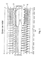
- Fig. 1 shows a representation of the cyclic operation of a Adsorptionshimltemaschine.
- the characteristic discontinuous mode of operation of the machine is characterized by the structure and the changing processes of adsorption and desorption. In order to keep the machine operating as continuously as possible, adsorption and desorption processes are alternately carried out in two adsorbers.
- the fluctuations In the outlet temperature of a heat transfer medium circuit shown in the curve C, the fluctuations are extremely steep and occur cyclically. These fluctuations are also reflected in a damped form at the inlet temperature of the heat transfer circuit at the curve D.
- the cyclical operation of the machine is particularly clearly expressed in the course of a cooling capacity shown by the curve E. In the example shown here, a maximum cooling capacity of 8 kW and a minimum cooling capacity of 2 kW is achieved.
- the outside temperature represented by the curve F shows up to a point X a course with natural fluctuations.
- the sudden increase in the outside temperature at point X is due to incident solar radiation.
- the increase in the outside temperature has a delayed rise in the inlet temperature at curve D and outlet temperature at curve C of the heat transfer circuit result.
- the reduction of the cooling capacity at curve E after point X is due to the temperature increase in the circuit.
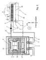
- FIG. 2 shows an exemplary recooling circuit 1 provided for the adsorption refrigerating machine 1
- FIG. 3 an exemplary embodiment of a circuit connected hybrid cooler.
- the recooling circuit contains a suitably arranged outdoors hybrid cooler 2 and a system 3, for example, a Adsorptionskarltemaschine with in Fig. 1 shown operating cycles, which gives off intermittently heat to the recooling circuit.
- the heat carrier flowing in the recooling circuit flows via a feed line 4 from the system into the hybrid cooler. There he transfers the heat absorbed by the system to the ambient air.
- a cooling element 5 is provided in a lamellar construction, which offers a particularly good thermal contact with the environment.
- the cooled in the hybrid cooler heat carrier flows back through a return line 6 to the plant.
- a pump 7 is provided for circulating the heat carrier within the recooling circuit.
- the flow of the heat carrier in the recooling circuit can be regulated via a series of valves. About arranged in the vicinity of the pump check valves 10, the flow can be locked if necessary.
- An associated with the recooling circuit reservoir and expansion tank 11 compensates for pressure fluctuations.
- a process medium flows within a process cycle.
- the process cycle corresponds to the cycle of the adsorbed and desorbed refrigerant which is customary in such systems.
- This exchanges heat via arranged in the circuit heat exchanger, in particular a condenser 13, two adsorbers 14 and an evaporator 15 with adjacent operating components.
- the evaporator 15 is thermally coupled to an external cold water circuit (not shown here).
- an external cold water circuit includes, for example, a cooling ceiling or a cooling coil. These facilities are not shown here.
- the adsorbers 14 are in turn thermally coupled to an external hot water circuit containing, for example, a solar storage, not shown here, a district heating device or a waste heat of a combined heat and power plant.
- an external hot water circuit containing, for example, a solar storage, not shown here, a district heating device or a waste heat of a combined heat and power plant.
- temperature sensors 16 are provided, in particular in the region of the condenser, the evaporator and / or the adsorber. These pass the operating parameters detected at these locations, i. the temperature values measured in this example, to a control unit 17.
- the hybrid cooler already mentioned is a dry hybrid cooler with a spraying device 18 and a ventilation system 19.
- the spraying device consists of a nozzle arrangement 20 arranged below the cooling element 5, which is supplied with cold water from a supply line 21.
- the water supply via the supply line can be released or shut off via a check valve 22.
- the opening state of the check valve is determined by the control unit 17 via a control line 17a and the transmitted via this line electrical switching signals.
- the check valve is for this purpose designed as an electrically switchable valve, for example as a solenoid valve.
- the nozzle arrangement is in the form of a nozzle block under the cooling element.
- the sucked ambient air thus flows first through the nozzle and rips the water sprayed there with it.
- the cooling element is wetted on its surface.
- An evaporation effect which occurs in the air volume flow and on the surface of the finned heat exchanger wall of the cooling element makes it possible to cool the heat carrier to a temperature which is below the ambient temperature.
- the cooling of the heat carrier in the recooling circuit is intensified.
- the spray can be activated or deactivated and thus the effectiveness of the cooling can be adjusted.
- Fig. 4 shows the effect of discontinuous spraying using an exemplary diagram.
- the diagram shows the time course of an exit temperature at the recooler under the influence of a discontinuous heat load during a work cycle of the adsorption chiller. This essentially repeats periodically.
- the curve A shows the temperature profile of the outlet temperature from the recooler without spraying
- the curve B indicates the temperature profile of the outlet temperature with Besprühung.
- the spraying is carried out during the working cycle within two time intervals t S1 . From the course of curve A, it can be seen that the temperature at the outlet of the recooler initially reaches a maximum which asymptotically decreases with time due to the incipient action of the recooler against a limit value.
- the initial temperature maximum is considerably reduced by the spraying during the first time interval t S1 .
- the temperature curve shows a much flatter course.
- the short-term spraying in the two time intervals is thus sufficient to smooth the temperature profile at the outlet of the hybrid cooler and thus a constant cooling capacity of the hybrid cooler to ensure a discontinuous heat load.
- the spraying performed only within the time intervals is sufficient to effectively dissipate the discontinuously supplied heat.
- This effect is caused by the reduced temperature of the ambient air sucked in by the ventilation due to the spraying.
- the temperature profile of the ambient air is represented by the curve B '.
- the beginning and the duration of the respective time intervals t S1 are determined by the control unit.
- the spraying then starts when the temperature T reaches or exceeds a desired value T soll at a point in the refrigeration cycle of the adsorption chiller. It is then turned off and the valve 22 is closed when the predetermined operating parameters, in this case, the target value T set, has fallen again.
- the strong flattening of the curve B in comparison to A is explained by the fact that the spraying of the cooling element in the hybrid cooler already starts before the now more heated heat transfer medium has reached the cooling element via the supply line. As a result, the cooling element is already wetted and can thus absorb the heat introduced by the heat transfer medium very effectively.
- the spraying thus starts at a point in time when the temperature of the heat carrier is still rising.
- the minimum reached in the curve B 'of the air temperature during the time interval t S1 thus coincides with the rising portion of the curve B of the outlet temperature.
- the effectiveness of regulated by the control unit intermittent spraying thus results primarily from the fact that the temperature rise of the heat carrier in the return cooling circuit is met timely and already at the beginning.
- Fig. 5 shows the beneficial influence of in Fig. 4 illustrated embodiment of the spraying on a machine operating a adsorption chiller with such operated recirculating cooling circuit at different ambient temperatures.
- the machine operating rate is a measure of the effectiveness of the adsorption chiller. It indicates the ratio between the heat pumped by the adsorption chiller and the energy required for it. A high machine operating count thus means a high efficiency of the refrigeration system.
- the graph shows that the machine operating count is expected to decrease as the outside temperature increases. It reaches a value of less than 10 without spraying at a temperature of 26 ° C. At this temperature the spraying follows according to the procedure Fig. 3 put into operation, the machine work rate increases significantly to a value of 15 and thus to one and a half times.
Landscapes
- Engineering & Computer Science (AREA)
- Physics & Mathematics (AREA)
- Thermal Sciences (AREA)
- Mechanical Engineering (AREA)
- General Engineering & Computer Science (AREA)
- Sorption Type Refrigeration Machines (AREA)
- Air Conditioning Control Device (AREA)
- Rectifiers (AREA)
Abstract
Description
Die Erfindung betrifft ein Verfahren zum Betreiben eines Rückkühlkreislaufes mit einem Hybridkühler für eine Anlage mit einer diskontinuierlich anfallenden Wärmeabgabe nach dem Oberbegriff des Anspruchs 1 und eine Vorrichtung hierfür nach dem Oberbegriff des Anspruchs 5.The invention relates to a method for operating a recooling circuit with a hybrid cooler for a system with a discontinuously occurring heat emission according to the preamble of
Rückkühler und Rückkühlkreisläufe werden eingesetzt, um Wärme von einer Wärmequelle an die Umgebung abzuführen. Dabei wird ein Rückkühlmedium verwendet, um die Wärme von der Wärmequelle zu einer Wärmeaustauschfläche zu leiten, die mit der Umgebung im thermischen Kontakt steht. Hierzu sind eine Vielzahl unterschiedlicher Konfigurationen bekannt. Die Wärmeabgabe an die Umgebung erfolgt entweder über einen trockenen Rückkühler, bei dem das Rückkühlmedium durch Rohre innerhalb der Wärmetauschfläche fließt und so die Wärme an die Umgebung überträgt, oder über einen Naßkühler, bei dem das überwiegend in Form von Wasser ausgebildete Rückkühlmedium direkt verdampft oder verdunstet, wie dies beispielsweise bei einem Kühlturm der Fall ist.Recoolers and recirculating cooling circuits are used to dissipate heat from a heat source to the environment. In this case, a recooling medium is used to conduct the heat from the heat source to a heat exchange surface, which is in thermal contact with the environment. For this purpose, a variety of different configurations are known. The heat is transferred to the environment either via a dry recooler, in which the recooling medium flows through pipes within the heat exchange surface and thus transfers the heat to the environment, or via a wet cooler, in which the predominantly formed in the form of water Rückkühlmedium directly evaporated or evaporated , as is the case for example with a cooling tower.
Bei einem Hybridkühler ist das Prinzip der trockenen Rückkühlung und der Nasskühlung kombiniert. Dabei erfolgt eine trockene Rückkühlung, welche durch eine Wasserbesprühung, -berieselung oder -benetzung der Kühlflächen oder der umgebenden Luft unterstützt wird.With a hybrid cooler, the principle of dry recooling and wet cooling is combined. In this case, there is a dry recooling, which is supported by water spraying, sprinkling or wetting the cooling surfaces or the surrounding air.
Die herkömmliche Steuerung des Betriebs eines Hybridkühlers erfolgt in der Weise, dass die Besprühung dann in Betrieb genommen wird, wenn sich eine bestimmte Temperatur in der Zuluft oder am Ausgang des Rückkühlers einstellt. Bei der Aktivierung der Besprühung wird ein Ventil geöffnet und es wird kontinuierlich Wasser in den Zuluftstrom eingesprüht. Durch die damit bewirkte Absenkung der Temperatur in der Zuluft wird eine höhere Wärmeabfuhr im Rückkühlkreislauf ermöglicht. Die Besprühung wird üblicherweise dadurch geregelt, indem die Temperatur am Rückkühleraustritt erfasst wird. Diese wird mit einem vorgegebenen Sollwert verglichen.The conventional control of the operation of a hybrid cooler is such that the spray is then put into operation when a certain temperature in the supply air or at the outlet of the recooler is established. Upon activation of the spray, a valve is opened and water is continuously sprayed into the supply air stream. By thus causing lowering of the temperature in the supply air, a higher heat dissipation in the recooling circuit is made possible. The spraying is usually controlled by detecting the temperature at the recooler outlet. This is compared with a predetermined setpoint.
Dieses Regelungsverfahren weist den Nachteil auf, dass sich der Wasserverbrauch bei der Besprühung und damit die Effizienz der Besprühung des Rückkühlers in einem nur sehr eingeschränkten Maße beeinflussen lässt. Das bekannte Regelungsverfahren ist für eine kontinuierliche Besprühung ausgelegt. Der Wasserverbrauch ist daher unverhältnismäßig groß, die ständige Besprühung führt außerdem zu Schmutz- und Kalkablagerungen im Rückkühler. Dies verschlechtert die Effizienz der Rückkühlung zusätzlich und führt wiederum zu einem zusätzlichen Wasserverbrauch bei der Besprühung.This control method has the disadvantage that the water consumption in the spraying and thus the efficiency of the spray of the recooler can be influenced to a very limited extent. The known control method is designed for continuous spraying. The water consumption is therefore disproportionately large, the constant spraying also leads to dirt and lime deposits in the recooler. This additionally worsens the efficiency of the re-cooling and in turn leads to an additional water consumption during the spraying.
Außerdem erweist sich die Regelung der Besprühung des Rückkühlers bei den derzeit bekannten Verfahren als nur sehr eingeschränkt variierbar. Sie weist technisch bedingt eine feste Hysterese auf, die verhindert, dass das Ein- und Ausschalten der Besprühung zeitgenau erfolgt. Der gesamte Regelvorgang gestaltet sich somit sehr träge.In addition, the regulation of the spray of the recooler proves to be very limited in the currently known methods. For technical reasons, it has a fixed hysteresis which prevents the spraying on and off being timed precisely. The entire control process is thus very slow.
Die genannten Nachteile werden besonders dann gravierend, wenn Anlagen rückzukühlen sind, die eine diskontinuierliche Wärmeabgabe aufweisen, die noch dazu innerhalb relativ kurzer zeitlicher Zyklen wechselt. Die herkömmlichen Steuerungsverfahren der Rückkühlung führen in diesem Fall dazu, dass die Besprühung immer dann nutzlos im Betrieb bleibt, wenn von der Anlage keine oder eine nur geringe Wärmemenge abzuführen ist. Das bekannte Steuerungsverfahren der Besprühung ist wegen dessen Trägheit nicht in der Lage, auf die sich verändernden zyklischen Wärmelasten der Anlage zu reagieren. Dadurch wird die Rückkühlung einer solchen Anlage ineffizient.The mentioned disadvantages become particularly serious when systems are to be recooled, which have a discontinuous heat output, which also changes within relatively short time cycles. The conventional recooling control procedures in this case result in the spray being useless in operation whenever it is discharged from the plant no or only a small amount of heat is dissipate. The known spraying control method, because of its inertia, is unable to respond to the changing cyclic heat loads of the plant. As a result, the re-cooling of such a system is inefficient.
Es besteht somit die Aufgabe, einen Rückkühlkreislauf mit einem Hybridkühler so zu gestalten, dass dieser sich besonders gut für Anlagen mit einer diskontinuierlichen Wärmeabgabe eignet. Der Rückkühlkreislauf soll insbesondere für Anlagen geeignet sein, bei der die Wärmeabgabe innerhalb vergleichsweise kurzer Zeitzyklen wechselt. Der Rückkühlkreislauf soll einen reduzierten Wasserverbrauch bei der Besprühung aufweisen, die Effizienz der Rückkühlung steigern und eine erhöhte Lebensdauer der in dem Rückkühlkreislauf vorhandenen Komponenten, insbesondere des Hybridkühlers selbst, gewährleisten. In Verbindung damit sollen die Betriebs- und Wartungskosten des Rückkühlkreislaufs und darüber hinaus der Anlage gesenkt und optimiert werden.It is therefore the object to make a recooling circuit with a hybrid cooler so that it is particularly well suited for systems with a discontinuous heat dissipation. The recooling circuit should be particularly suitable for systems in which the heat transfer within relatively short time cycles changes. The recooling circuit should have a reduced water consumption during the spraying, increase the efficiency of the recooling and ensure an increased life of the components present in the recooling circuit, in particular of the hybrid cooler itself. In conjunction with this, the operating and maintenance costs of the recooling circuit and beyond the system should be lowered and optimized.
Die Aufgabe wird hinsichtlich des Verfahrensaspektes gemäß der Lehre zum Betreiben eines Rückkühlkreislaufes mit den Merkmalen des Anspruchs 1 und hinsichtlich des Vorrichtungsaspektes mit einer Vorrichtung zum Betreiben eines Rückkühlkreislaufes mit den Merkmalen des Anspruchs 5 gelöst. Die jeweiligen Unteransprüche enthalten zweckmäßige und/oder vorteilhafte Ausführungsformen des Verfahrens oder der Vorrichtung.The object is achieved with regard to the method aspect according to the teaching for operating a recooling circuit having the features of
Erfindungsgemäß zeichnet sich das Verfahren zum Betreiben eines Rückkühlkreislaufes mit einem Hybridkühler für eine Anlage mit einer diskontinuierlichen Wärmeabgabe durch eine Besprühregelung des Hybridkühlers mit folgenden Verfahrensschritten aus:
- Es erfolgt ein kontinuierliches Erfassen eines aktuellen Betriebsparameters innerhalb der Anlage. Der so erfasste Betriebsparameter wird mit einem vorgegebenen ersten Wert in einer Regeleinheit verglichen. Eine Besprüheinrichtung des Hybridkühlers wird bei einem Erreichen und/oder Überschreiten des vorgegebenen Wertes durch den aktuell erfassten Betriebsparameter aktiviert, bis ein vorgegebener zweiter Wert erreicht und/oder unterschritten worden ist.
- There is a continuous recording of a current operating parameter within the system. The operating parameter thus detected is compared with a predetermined first value in a control unit. A Sprühheinrichtung the hybrid cooler is at a reaching and / or exceeding the predetermined Values activated by the currently detected operating parameters until a predetermined second value has been reached and / or fallen below.
Die Besprüheinrichtung bleibt so lange aktiviert, wie der betreffende Betriebsparameter überschritten ist. Danach wird die Besprüheinrichtung deaktiviert, indem ein Ventil geschlossen wird. Alternativ kann das Ventil während eines festen Intervalls geöffnet oder geschlossen werden, sodass der Hybridkühler intervallartig besprüht wird.The spraying device remains activated as long as the relevant operating parameter is exceeded. Thereafter, the sprayer is deactivated by closing a valve. Alternatively, the valve can be opened or closed during a fixed interval so that the hybrid cooler is sprayed at intervals.
Bei einer Ausführungsform des Verfahrens ist die Anlage mit der diskontinuierlichen Wärmeabgabe eine Adsorptionskältemaschine. Der Betriebsparameter ist bei einer Ausführungsform des Verfahrens eine Temperatur innerhalb der Anlage.In one embodiment of the process, the discontinuous heat removal plant is an adsorption chiller. The operating parameter in one embodiment of the method is a temperature within the system.
Bei einer Ausführungsform erfolgt ein kontinuierliches Erfassen einer aktuellen Temperatur innerhalb eines Wärmeträgerkreislaufes der Adsorptionskälteanlage. Die so erfasste aktuelle Temperatur wird mit einem vorgegebenen Temperatursollwert in einer Regeleinheit verglichen. Eine Besprüheinrichtung des Hybridkühlers wird durch die Regeleinheit dann aktiviert, wenn der Temperatursollwert durch die aktuelle Temperatur erreicht und/oder überschritten wird. Diese Aktivierung hält so lange an, bis ein Unterschreiten des Temperatursollwertes durch die aktuelle Temperatur stattfindet und wird anschließend beendet.In one embodiment, a continuous detection of a current temperature takes place within a heat carrier circuit of the adsorption refrigeration system. The thus detected current temperature is compared with a predetermined temperature setpoint in a control unit. A spraying device of the hybrid cooler is activated by the control unit when the temperature setpoint is reached and / or exceeded by the current temperature. This activation continues until an undershooting of the temperature setpoint takes place due to the current temperature and is then terminated.
Im Gegensatz zu der herkömmlichen Steuerung der Besprüheinrichtung, die auf den Temperaturwert am Ausgang des Rückkühlers rückgekoppelt ist, wird ein Betriebsparameter, beispielsweise ein Temperaturwert, aus der Anlage selbst zur Regelung der Besprüheinrichtung verwendet. Der Betrieb der Besprüheinrichtung ist somit unmittelbar mit den Betriebsabläufen der Anlage und damit mit dem dort ablaufenden wärmeerzeugenden Prozess gekoppelt. Die Besprüheinrichtung reagiert somit unmittelbar auf die Betriebsabläufe und damit auf die Wärmeerzeugung innerhalb der Anlage. Dadurch werden die Ansprechzeiten der Regelung der Besprüheinrichtung entscheidend verkürzt, sodass ein echter diskontinuierlicher und/oder zyklischer Betrieb der Besprüheinrichtung entsprechend der diskontinuierlichen Wärmeerzeugung innerhalb der Anlage ausführbar ist. Die Besprüheinrichtung reagiert dadurch insbesondere auf innerhalb der Anlage ablaufende Betriebszyklen und ist mit diesen gekoppelt. Damit wird die zum Besprühen verbrauchte Wassermenge und somit die Beanspruchung des Hybridkühlers nachhaltig gesenkt und der Rückkühlkreislauf in effektiver Weise auf die von der Anlage gelieferte Wärmelast eingestellt.In contrast to the conventional control of the spraying device, which is fed back to the temperature value at the outlet of the recooler, an operating parameter, for example a temperature value, from the system itself is used to control the spraying device. The operation of the spraying device is thus directly coupled with the operating sequences of the system and thus with the heat-generating process occurring there. The spraying device thus reacts directly to the operating processes and thus to the heat generation within the system. As a result, the response times of the control of the sprayer are significantly shortened, so a true discontinuous and / or cyclical operation of the spraying device according to the discontinuous heat generation within the plant is executable. The spraying device thereby reacts in particular to operating cycles running within the system and is coupled to these. Thus, the amount of water consumed for spraying and thus the stress on the hybrid cooler is lowered sustainably and set the recirculation circuit in an effective manner to the heat load delivered by the system.
Die Anlage kann als eine Adsorptionskältemaschine ausgeführt sein. Dabei wird der aktuell erfasste Betriebsparameter innerhalb eines Verdampfers in einem Kaltwasserkreislauf oder einem Kondensator in der Adsorptionskältemaschine erfasst. Bei einem Erreichen und/oder Überschreiten des Betriebssollwertes wird über eine Regeleinheit ein Schaltsignal zum Öffnen eines Ventils in der Besprüheinrichtung ausgegeben, bis sich der Sollwert des Betriebsparameters wieder einstellt oder eine maximale Besprühdauer überschritten worden ist.The plant can be designed as an adsorption chiller. In this case, the currently detected operating parameter is detected within an evaporator in a cold water circuit or a condenser in the adsorption refrigerator. When the operating setpoint is reached and / or exceeded, a switching signal for opening a valve in the spraying device is output via a control unit until the desired value of the operating parameter sets again or a maximum spraying time has been exceeded.
Adsorptionskältemaschinen zeichnen sich durch eine diskontinuierlich erzeugte und zyklische Wärmeabgabe aus. Für derartige Zwecke ist der erfindungsgemäß betriebene Rückkühlkreislauf somit besonders vorteilhaft.Adsorption chillers are characterized by a discontinuously generated and cyclic heat output. For such purposes, the inventively operated Rückkühlkreislauf is thus particularly advantageous.
Vorrichtungsseitig zeichnet sich der erfindungsgemäße Rückkühlkreislauf mit Hybridkühler für eine Anlage mit einer diskontinuierlichen Wärmeabgabe durch eine Sensorvorrichtung zum Erfassen eines Betriebsparameters innerhalb der Anlage, eine mit der Sensorvorrichtung gekoppelte Regeleinheit mit einem Vergleichsglied und einem mit der Regeleinheit gekoppelten Ventil in einer Besprüheinrichtung des Hybridkühlers aus.On the device side, the recooling circuit with hybrid cooler according to the invention for a system with a discontinuous heat output by a sensor device for detecting an operating parameter within the system, a control unit coupled to the sensor device with a comparison member and a valve coupled to the control unit in a spraying of the hybrid radiator.
Die Anlage ist bei einer vorteilhaften Ausführungsform eine Adsorptionskältemaschine, wobei der Temperatursensor im Bereich einer Sekundärseite eines Adsorbers, Kondensators und/oder Verdampfers der Kältemaschine angeordnet ist. Der Hybridkühler ist bei einer Ausführungsform als ein Trockenrückkühler mit Ventilation und Besprühung in Ventilationsrichtung ausgebildet.In an advantageous embodiment, the plant is an adsorption refrigerating machine, wherein the temperature sensor is arranged in the region of a secondary side of an adsorber, condenser and / or evaporator of the refrigerating machine is. The hybrid radiator in one embodiment is configured as a dry recooler with ventilation and spraying in the direction of ventilation.
Das Verfahren und die Vorrichtung zum Ausführen des Verfahrens sollen nachfolgend anhand von Ausführungsbeispielen näher erläutert werden. Zur Verdeutlichung dienen die
Hierbei zeigen:
- Fig. 1
- eine Darstellung einer zyklischen Arbeitsweise einer Adsorptionskältemaschine,
- Fig. 2
- eine Darstellung eines beispielhaften Rückkühlkreislaufs im Überblick,
- Fig. 3
- eine zweckmäßige Ausführungsform eines beispielhaften Hybridkühlers,
- Fig. 4
- eine Darstellung eines Temperaturverlaufs am Austritt eines Hybridkühlers unter dem Einfluss einer zeitlich diskontinuierlichen Wärmelast mit und ohne Besprühungsintervalle und
- Fig. 5
- eine Darstellung einer Maschinenarbeitszahl einer rückgekühlten Adsorptionskältemaschine in Abhängigkeit von einer Außentemperatur mit und ohne Besprühung.
- Fig. 1
- a representation of a cyclic operation of an adsorption chiller,
- Fig. 2
- a representation of an exemplary recooling cycle at a glance,
- Fig. 3
- an expedient embodiment of an exemplary hybrid cooler,
- Fig. 4
- a representation of a temperature profile at the outlet of a hybrid cooler under the influence of a time-discontinuous heat load with and without Sprühungsintervalle and
- Fig. 5
- a representation of an engine operating coefficient of a recooled adsorption refrigeration machine as a function of an outside temperature with and without spraying.
Nachfolgend wird das erfindungsgemäße Verfahren anhand eines Betriebs eines mit einer Adsorptionskältemaschine gekoppelten Rückkühlkreislaufes, insbesondere eines Rückkühlwasserkreislaufes, beispielhaft dargestellt. Wie für alle thermisch angetriebenen Kälteanlagen, ist auch für derartige Anlagen eine leistungsfähige und effiziente Rückkühlung der zugeführten Antriebsenergie und der erzeugten Kälteenergie von großer Bedeutung. Die von der Maschine nicht weiter verwertbare Rückkühlenergie in Form von Wärme muss daher über den Rückkühlkreislauf und über einen Wärmeaustausch effizient abgeführt werden. Hierzu zirkuliert in dem Rückkühlkreislauf ein Wärmeträger, der beispielsweise aus Wasser oder einem Gemisch aus Wasser und Glykol besteht.The method according to the invention is illustrated by way of example below on the basis of an operation of a recooling circuit, in particular a recooling water circuit, coupled to an adsorption refrigerating machine. As for all thermally driven refrigeration systems, efficient and efficient re-cooling of the supplied drive energy and the generated cooling energy is also of great importance for such systems. The one from the machine Therefore, reusable energy in the form of heat, which can no longer be utilized, must be efficiently removed via the recooling circuit and via a heat exchange. For this purpose circulates in the recooling circuit, a heat carrier, which consists for example of water or a mixture of water and glycol.
Durch die Wärmeaufnahme in der Maschine steigt die Wärmeträgertemperatur im Rückkühlkreislauf. Der Wärmeträger wird entlang des Rückkühlkreislaufs und insbesondere an einem als ein Wärmeübertrager ausgebildeten Kühler wieder auf ein niedrigeres Temperaturniveau abgekühlt. Er steht danach der Kälteanlage somit für die erneute Wärmeaufnahme zur Verfügung. Die Effizienz und die Leistung des Rückkühlkreislaufs sind von der Außentemperatur, der Art des eingesetzten Kühlers, dessen Peripheriekomponenten und der Kälteanlage selbst abhängig.Due to the heat absorption in the machine, the heat carrier temperature in the recooling circuit increases. The heat transfer medium is cooled down to a lower temperature level along the recooling circuit and in particular on a cooler designed as a heat exchanger. He is then the refrigeration system thus for the new heat absorption available. The efficiency and performance of the recooling circuit depend on the outside temperature, the type of cooler used, its peripheral components and the refrigeration system itself.
Die durch die Kurve F dargestellte Außentemperatur zeigt bis zu einem Punkt X einen Verlauf mit natürlichen Schwankungen. Der sprunghafte Anstieg der Außentemperatur im Punkt X ist auf einfallende Sonnenstrahlung zurückzuführen. Der Anstieg der Außentemperatur hat einen verzögerten Anstieg der Eintrittstemperatur bei Kurve D und Austrittstemperatur bei Kurve C des Wärmeträgerkreislaufs zur Folge. Die nach dem Punkt X erfolgende Minderung der Kälteleistung bei Kurve E ist auf die Temperaturerhöhung im Kreislauf zurückzuführen.The outside temperature represented by the curve F shows up to a point X a course with natural fluctuations. The sudden increase in the outside temperature at point X is due to incident solar radiation. The increase in the outside temperature has a delayed rise in the inlet temperature at curve D and outlet temperature at curve C of the heat transfer circuit result. The reduction of the cooling capacity at curve E after point X is due to the temperature increase in the circuit.
Der Rückkühlkreislauf enthält einen zweckmäßigerweise im Freien angeordneten Hybridkühler 2 und eine Anlage 3, beispielsweise eine Adsorptionskältemaschine mit den in
Der in dem Hybridkühler abgekühlte Wärmeträger strömt über einen Rücklauf 6 zur Anlage zurück. Zum Umwälzen des Wärmeträgers innerhalb des Rückkühlkreislaufs ist eine Pumpe 7 vorgesehen. Der Fluss des Wärmeträgers im Rückkühlkreislauf kann über eine Reihe von Ventilen geregelt werden. Über in der Nähe der Pumpe angeordnete Sperrventile 10 kann der Vorlauf bei Bedarf gesperrt werden. Ein mit dem Rückkühlkreislauf verbundener Vorrats- und Ausgleichsbehälter 11 kompensiert Druckschwankungen.The cooled in the hybrid cooler heat carrier flows back through a
Innerhalb der von dem Rückkühlkreislauf gekühlten Anlage strömt ein Prozessmedium innerhalb eines Prozesskreislaufes. Bei einer Adsorptionskältemaschine entspricht der Prozesskreislauf dem bei derartigen Anlagen üblichen Kreislauf des adsorbierten und desorbierten Kältemittels. Dieser tauscht Wärme über in dem Kreislauf angeordnete Wärmetauscher, insbesondere einen Kondensator 13, zwei Adsorbern 14 und einen Verdampfer 15 mit angrenzenden Betriebskomponenten aus.Within the system cooled by the recooling circuit, a process medium flows within a process cycle. In the case of an adsorption chiller, the process cycle corresponds to the cycle of the adsorbed and desorbed refrigerant which is customary in such systems. This exchanges heat via arranged in the circuit heat exchanger, in particular a
Der Verdampfer 15 ist hierzu thermisch an einen hier nicht gezeigten externen Kaltwasserkreislauf gekoppelt. Dieser schließt beispielsweise ein Kühldecke oder eine Kühlspirale ein. Diese Einrichtungen sind hier nicht dargestellt.For this purpose, the
Die Adsorber 14 sind wiederum thermisch an einen externen Heißwasserkreislauf gekoppelt, der beispielsweise einen hier nicht dargestellten Solarspeicher, eine Fernwärmeeinrichtung oder eine Abwärmeeinrichtung eines Blockheizkraftwerk enthält.The
An verschiedenen Stellen der Sekundärseiten der Wärmetauscher oder auch im Rückkühlkreislauf sind, insbesondere im Bereich des Kondensators, des Verdampfers und/oder der Adsorber, Temperatursensoren 16 vorgesehen. Diese übergeben die an diesen Stellen erfassten Betriebsparameter, d.h. die in diesem Beispiel gemessenen Temperaturwerte, an eine Regeleinheit 17.At various points on the secondary sides of the heat exchangers or in the recooling circuit,
Bei dem bereits erwähnten Hybridkühler handelt es sich um einen Trockenhybridkühler mit einer Besprüheinrichtung 18 und einer Ventilation 19. Die Besprüheinrichtung besteht aus einer unter dem Kühlelement 5 angeordneten Düsenanordnung 20, die von einer Zulaufleitung 21 mit Kaltwasser versorgt wird. Die Wasserzufuhr über die Zulaufleitung kann über ein Sperrventil 22 freigegeben oder abgesperrt werden. Der Öffnungszustand des Sperrventils wird von der Regeleinheit 17 über eine Steuerleitung 17a sowie die über diese Leitung übermittelten elektrischen Schaltsignale bestimmt. Das Sperrventil ist hierzu als ein elektrisch schaltbares Ventil, beispielsweise als ein Magnetventil, ausgebildet.The hybrid cooler already mentioned is a dry hybrid cooler with a
Bei dem hier vorliegenden Aufbau des Hybridkühlers wird Umgebungsluft durch die Ventilation angesaugt. Diese durchströmt das Kühlelement und tritt aus dem Hybridkühler wieder aus. Bei dem Trockenrückkühler mit Besprühung in Ventilationsrichtung befindet sich die Düsenanordnung in Form eines Düsenstocks unter dem Kühlelement. Die angesaugte Umgebungsluft strömt somit zuerst durch den Düsenstock und reißt das dort eingesprühte Wasser mit sich. Durch das Einsprühen von Wasser in die Strömungsrichtung des Luftvolumenstroms wird das Kühlelement an dessen Oberfläche benetzt. Ein zum einem in dem Luftvolumenstrom und zum anderen auf der Oberfläche der Lamellenwärmetauscherwand des Kühlelementes auftretender Verdunstungseffekt ermöglicht eine Abkühlung des Wärmeträgers auf eine Temperatur, die unterhalb der Umgebungstemperatur liegt. Dadurch wird die Kühlung des Wärmeträgers im Rückkühlkreislauf intensiviert. Über den Schaltzustand des Sperrventils kann die Besprühung aktiviert oder deaktiviert und somit die Effektivität der Kühlung eingestellt werden.In the structure of the hybrid cooler present here, ambient air is sucked in through the ventilation. This flows through the cooling element and exits the hybrid cooler again. In the dry recooler with spray in the direction of ventilation, the nozzle arrangement is in the form of a nozzle block under the cooling element. The sucked ambient air thus flows first through the nozzle and rips the water sprayed there with it. By spraying water in the flow direction of the air flow the cooling element is wetted on its surface. An evaporation effect which occurs in the air volume flow and on the surface of the finned heat exchanger wall of the cooling element makes it possible to cool the heat carrier to a temperature which is below the ambient temperature. As a result, the cooling of the heat carrier in the recooling circuit is intensified. About the switching state of the check valve, the spray can be activated or deactivated and thus the effectiveness of the cooling can be adjusted.
Die Kurve A zeigt dabei den Temperaturverlauf der Austrittstemperatur aus dem Rückkühler ohne Besprühung, die Kurve B gibt den Temperaturverlauf der Austrittstemperatur mit Besprühung an. Bei dem hier gezeigten Beispiel wird die Besprühung während des Arbeitszyklus' innerhalb von zwei Zeitintervallen tS1 ausgeführt. Aus dem Verlauf der Kurve A ist zu entnehmen, dass die Temperatur am Austritt des Rückkühlers zunächst ein Maximum erreicht, das mit der Zeit durch die einsetzende Wirkung des Rückkühlers asymptotisch gegen einen Grenzwert sinkt.The curve A shows the temperature profile of the outlet temperature from the recooler without spraying, the curve B indicates the temperature profile of the outlet temperature with Besprühung. In the example shown here, the spraying is carried out during the working cycle within two time intervals t S1 . From the course of curve A, it can be seen that the temperature at the outlet of the recooler initially reaches a maximum which asymptotically decreases with time due to the incipient action of the recooler against a limit value.
Wie der Verlauf der Kurve B zeigt, wird durch die während des ersten Zeitintervalls tS1 erfolgende Besprühung das anfängliche Temperaturmaximum beträchtlich gesenkt. Die Temperaturkurve zeigt im Anschluss daran einen weitaus flacheren Verlauf. Im Gegensatz zu dem Temperaturverlauf bei Kurve A kann durch eine spätere, wiederum innerhalb eines Zeitintervalls tS1 erfolgende Besprühung die zum Zeitpunkt t = 0 vorliegende Anfangstemperatur schnell wieder erreicht werden. Die kurzzeitige Besprühung in den beiden Zeitintervallen genügt somit, um den Temperaturverlauf am Austritt des Hybridkühlers zu glätten und somit eine gleichbleibende Kühlleistung des Hybridkühlers bei einer diskontinuierlichen Wärmelast zu gewährleisten. Die nur innerhalb der Zeitintervalle ausgeführte Besprühung reicht aus, um die diskontinuierlich herangeführte Wärme effektiv abzuführen.As the curve B shows, the initial temperature maximum is considerably reduced by the spraying during the first time interval t S1 . The temperature curve then shows a much flatter course. In contrast to the temperature profile in curve A, the initial temperature present at the time t = 0 can be quickly reached again by a subsequent spraying, again taking place within a time interval t S1 . The short-term spraying in the two time intervals is thus sufficient to smooth the temperature profile at the outlet of the hybrid cooler and thus a constant cooling capacity of the hybrid cooler to ensure a discontinuous heat load. The spraying performed only within the time intervals is sufficient to effectively dissipate the discontinuously supplied heat.
Dieser Effekt wird durch die infolge der Besprühung herabgesetzte Temperatur der über die Ventilation angesaugten Umgebungsluft bewirkt. Der Temperaturverlauf der Umgebungsluft ist durch die Kurve B' dargestellt.This effect is caused by the reduced temperature of the ambient air sucked in by the ventilation due to the spraying. The temperature profile of the ambient air is represented by the curve B '.
Der Beginn und die Dauer der jeweiligen Zeitintervalle tS1 werden von der Regeleinheit bestimmt. Die Besprühung setzt dann ein, wenn die Temperatur T an einer Stelle des Kältekreislaufs der Adsorptionskältemaschine einen Sollwert Tsoll erreicht oder überschreitet. Sie wird dann deaktiviert und das Ventil 22 geschlossen, wenn der vorgegebene Betriebsparameter, in diesem Fall der Sollwert Tsoll, wieder unterschritten wird. Die starke Abflachung des Kurvenverlaufs B im Vergleich zu A erklärt sich dadurch, dass die Besprühung des Kühlelementes im Hybridkühlers bereits dann einsetzt, bevor der nun stärker erwärmte Wärmeträger das Kühlelement über den Vorlauf erreicht hat. Dadurch ist das Kühlelement bereits benetzt und kann somit die von dem Wärmeträger herangeführte Wärme sehr effektiv aufnehmen.The beginning and the duration of the respective time intervals t S1 are determined by the control unit. The spraying then starts when the temperature T reaches or exceeds a desired value T soll at a point in the refrigeration cycle of the adsorption chiller. It is then turned off and the
Wie aus dem Diagramm auch hervorgeht, setzt die Besprühung somit zu einem Zeitpunkt ein, wenn die Temperatur des Wärmeträgers noch im Steigen begriffen ist. Das während des Zeitintervalls tS1 erreichte Minimum in der Kurve B' der Lufttemperatur fällt damit zeitlich mit dem ansteigenden Abschnitt der Kurve B der Austrittstemperatur zusammen. Die Wirksamkeit der durch die Regeleinheit geregelten intervallartigen Besprühung ergibt sich somit vor allem daraus, dass dem Temperaturanstieg des Wärmeträgers im Rückkühlkreislauf zeitgenau und bereits zu Beginn begegnet wird.As can also be seen from the diagram, the spraying thus starts at a point in time when the temperature of the heat carrier is still rising. The minimum reached in the curve B 'of the air temperature during the time interval t S1 thus coincides with the rising portion of the curve B of the outlet temperature. The effectiveness of regulated by the control unit intermittent spraying thus results primarily from the fact that the temperature rise of the heat carrier in the return cooling circuit is met timely and already at the beginning.
Ein versuchsweise ausgeführter Vergleich der genannten Besprühart für den Hybridrückkühler mit der herkömmlichen Betriebsweise einer quasi kontinuierlichen Besprühung zeigt, dass bei dem Ausführen letzterer eine erheblich größere Wassermenge verbraucht wird. Im Vergleich zur herkömmlichen Betriebsweise ist bei dem erfindungsgemäßen Verfahren der Wasserverbrauch bei der Besprühung auf etwa ein Siebentel reduziert.An experimentally performed comparison of the mentioned Sprühart for the hybrid chiller with the conventional operation of a quasi-continuous spraying shows that in the execution of the latter, a significantly larger amount of water is consumed. Compared to the conventional mode of operation In the method according to the invention, the water consumption during the spraying is reduced to about one seventh.
Das Diagramm zeigt, dass die Maschinenarbeitszahl erwartungsgemäß bei zunehmender Außentemperatur sinkt. Sie erreicht ohne Besprühung etwa einen Wert von weniger als 10 bei einer Temperatur von 26 °C. Wird bei dieser Temperatur die Besprühung gemäß der Vorgehensweise nach
Das erfindungsgemäße Verfahren und die Vorrichtung wurden anhand von Ausführungsbeispielen näher erläutert. Im Rahmen fachmännischen Handelns sind weitere Ausgestaltungen des Verfahrens und der Vorrichtung möglich. Diese verbleiben sämtlich im Bereich des erfindungsgemäßen Grundgedankens. Weitere Ausführungsformen ergeben sich aus den Unteransprüchen.The method and the device according to the invention were explained in more detail by means of exemplary embodiments. In the context of professional action, further embodiments of the method and the device are possible. These remain all within the scope of the inventive concept. Further embodiments emerge from the subclaims.
- 11
- RückkühlkreislaufRear cooling circuit
- 22
- Hybridkühlerhybrid cooler
- 33
- Anlage mit diskontinuierlicher WärmeabgabePlant with discontinuous heat emission
- 44
- Vorlaufleader
- 55
- Kühlelementcooling element
- 66
- Rücklaufreturns
- 77
- Pumpepump
- 1010
- Sperrventilecheck valves
- 1111
- Vorrats- und AusgleichsbehälterReservoir and expansion tank
- 1313
- Kondensatorcapacitor
- 1414
- Adsorberadsorber
- 1515
- VerdampferEvaporator
- 1616
- Temperatursensortemperature sensor
- 1717
- Regeleinheitcontrol unit
- 17a17a
- Steuerleitungcontrol line
- 1818
- BesprüheinrichtungSpraying Device
- 1919
- Ventilationventilation
- 2020
- Düsenanordnungnozzle assembly
- 2121
- Zulaufleitungsupply line
- 2222
- Sperrventilcheck valve
- AA
- Austrittstemperatur ohne BesprühungExit temperature without spraying
- BB
- Austrittstemperatur mit IntervallbesprühungExit temperature with interval spray
- B'B '
- Temperatur der UmgebungsluftTemperature of the ambient air
- CC
- zyklisch variierende Austrittstemperatur im Wärmeträgerkreislauf einer AKMCyclically varying outlet temperature in the heat transfer circuit of an AKM
- DD
- zyklisch variierende Eintrittstemperatur im Wärmeträgerkreislauf der AKMcyclically varying inlet temperature in the heat transfer circuit of the AKM
- Ee
- zyklisch variierende Kälteleistung der AKMcyclically varying cooling capacity of the AKM
Claims (8)
gekennzeichnet durch
eine Besprühregelung des Hybridkühler mit folgenden Verfahrensschritten:
marked by
a spraying of the hybrid cooler with the following process steps:
dadurch gekennzeichnet, dass
die Anlage (3) eine Adsorptionskältemaschine ist.Method according to claim 1,
characterized in that
the plant (3) is an adsorption chiller.
dadurch gekennzeichnet, dass
der aktuell erfasste Betriebsparameter eine Temperatur (T) in der Anlage ist.Method according to claim 1 or 2,
characterized in that
the currently detected operating parameter is a temperature (T) in the system.
dadurch gekennzeichnet, dass
characterized in that
eine Sensorvorrichtung (16) zum Erfassen eines Betriebsparameters innerhalb der Anlage, eine mit der Sensorvorrichtung gekoppelte Regeleinheit mit einem Vergleichsglied und einem mit der Regeleinheit gekoppelten Ventil (22) in einer Besprüheinrichtung des Hybridkühlers.Device for operating a recooling circuit (1) with a hybrid cooler (2) for a system (3) with discontinuous heat dissipation, characterized by
a sensor device (16) for detecting an operating parameter within the system, a control unit coupled to the sensor device with a comparison element and a valve (22) coupled to the control unit in a spraying device of the hybrid cooler.
dadurch gekennzeichnet, dass
die Anlage eine Adsorptionskältemaschine ist, wobei die Sensorvorrichtung (16) als eine am Verdampfer und/oder Kondensator der Adsorptionskältemaschine angeordnete Temperaturmesseinrichtung ausgebildet ist.Device according to claim 5,
characterized in that
the system is an adsorption chiller, wherein the sensor device (16) is designed as a temperature measuring device arranged on the evaporator and / or condenser of the adsorption chiller.
dadurch gekennzeichnet, dass
ein Temperatursensor (16) innerhalb eines Wärmeträgerkreislaufs der Anlage, eine mit dem Temperatursensor gekoppelte Regeleinheit (17) mit einem Vergleichsglied und einer Umschalteinheit und einem mit der Umschalteinheit gekoppelten Ventil (22) in einer Besprüheinrichtung (18) des Hybridkühlers vorgesehen ist.Device according to one of claims 5 and 6,
characterized in that
a temperature sensor (16) within a heat carrier circuit of the system, a control unit (17) coupled to the temperature sensor with a comparison element and a switching unit and a valve (22) coupled to the switching unit is provided in a spray device (18) of the hybrid cooler.
dadurch gekennzeichnet, dass
der Hybridkühler (2) als ein Trockenrückkühler mit Ventilation und Besprühung in Ventilationsrichtung ausgebildet ist.Device according to one of the preceding claims,
characterized in that
the hybrid cooler (2) is designed as a dry recooler with ventilation and spraying in the ventilation direction.
Applications Claiming Priority (2)
| Application Number | Priority Date | Filing Date | Title |
|---|---|---|---|
| DE102009051888 | 2009-11-04 | ||
| DE102010008408.5A DE102010008408B4 (en) | 2009-11-04 | 2010-02-18 | Method for operating a recooling circuit with a hybrid cooler for a system with a discontinuous heat output and apparatus therefor |
Publications (3)
| Publication Number | Publication Date |
|---|---|
| EP2320189A2 true EP2320189A2 (en) | 2011-05-11 |
| EP2320189A3 EP2320189A3 (en) | 2014-09-03 |
| EP2320189B1 EP2320189B1 (en) | 2020-07-22 |
Family
ID=43530901
Family Applications (1)
| Application Number | Title | Priority Date | Filing Date |
|---|---|---|---|
| EP10188007.8A Active EP2320189B1 (en) | 2009-11-04 | 2010-10-19 | Method for operating a recooling circuit with a hybrid cooler for an assembly with discontinuous heat discharge |
Country Status (3)
| Country | Link |
|---|---|
| EP (1) | EP2320189B1 (en) |
| DE (1) | DE102010008408B4 (en) |
| ES (1) | ES2820876T3 (en) |
Families Citing this family (2)
| Publication number | Priority date | Publication date | Assignee | Title |
|---|---|---|---|---|
| DE202014101463U1 (en) | 2013-12-23 | 2014-06-20 | Entrade Energiesysteme Ag | Modular system for the provision of thermal and electrical energy |
| CN109612184A (en) * | 2018-11-13 | 2019-04-12 | 上海可瑞视冷链科技有限公司 | A kind of radiator of movable square compartment condenser |
Family Cites Families (7)
| Publication number | Priority date | Publication date | Assignee | Title |
|---|---|---|---|---|
| HU165521B (en) | 1972-07-03 | 1974-09-28 | ||
| DE3408192C2 (en) | 1984-03-06 | 1987-03-26 | Markus 8058 Erding Rothmeyer | Method for transforming the temperature of heat and heat transformer |
| DE4215898C2 (en) | 1992-04-09 | 1997-09-04 | E W Gohl Gmbh | Process for cooling liquid in a closed primary circuit and cooling device therefor |
| DE19906954A1 (en) | 1999-02-19 | 2000-08-24 | E W Gohl Gmbh | Cooling liquids involves forming heat exchangers with spray generators forming spray areas on sprayed surface of lamella packet; spray regions lie close together, are in contact or overlap |
| DE20001528U1 (en) * | 2000-01-28 | 2000-04-06 | Kühlturm GmbH, 76189 Karlsruhe | Cooler |
| US6823684B2 (en) | 2002-02-08 | 2004-11-30 | Tim Allan Nygaard Jensen | System and method for cooling air |
| US7310958B2 (en) | 2004-03-08 | 2007-12-25 | Baltimore Aircoil Company, Inc. | Control of heat exchanger operation |
-
2010
- 2010-02-18 DE DE102010008408.5A patent/DE102010008408B4/en not_active Expired - Fee Related
- 2010-10-19 ES ES10188007T patent/ES2820876T3/en active Active
- 2010-10-19 EP EP10188007.8A patent/EP2320189B1/en active Active
Non-Patent Citations (1)
| Title |
|---|
| None |
Also Published As
| Publication number | Publication date |
|---|---|
| DE102010008408B4 (en) | 2019-07-11 |
| EP2320189A3 (en) | 2014-09-03 |
| EP2320189B1 (en) | 2020-07-22 |
| ES2820876T3 (en) | 2021-04-22 |
| DE102010008408A1 (en) | 2011-07-14 |
Similar Documents
| Publication | Publication Date | Title |
|---|---|---|
| DE2748415C2 (en) | Heating method and bimodal heating system for heating buildings | |
| DE2754626C2 (en) | Refrigeration system operating with an energy source at a relatively low temperature, in particular solar energy | |
| DE3005291A1 (en) | METHOD AND DEVICE FOR CONDITIONING AIR BY DRYING WITH A SORBENT MATERIAL | |
| DE112013003304T5 (en) | Vehicle air conditioning unit | |
| EP2199706B1 (en) | A switching device air conditioner and operation method thereof | |
| DE3907859C2 (en) | Air-cooled refrigeration unit with a coolant circuit | |
| DE3938875A1 (en) | Mobile air conditioner stores energy in phase-change - medium for subsequent usage in heating water supply | |
| DE202011111059U1 (en) | heat pump system | |
| DE102010008408B4 (en) | Method for operating a recooling circuit with a hybrid cooler for a system with a discontinuous heat output and apparatus therefor | |
| CH649371A5 (en) | Air-conditioning device | |
| EP1792126A1 (en) | Device for supplying heat to at least one consumer and/or carrying heat away from the same | |
| DE1288615B (en) | Device for cooling a chamber | |
| DE10318655B3 (en) | Climate-control system for automobile with short-term cold store used during engine energy-saving operating mode upon short-term standstill of automobile | |
| EP3480534B1 (en) | Heating system and control method for a heating system | |
| DE102014205005A1 (en) | Method for operating the air conditioning system of a motor vehicle, air conditioning system for a motor vehicle | |
| WO2013152749A2 (en) | Cooling device for a switch cabinet and a corresponding method | |
| DE102007062343A1 (en) | Cold production method for water lithium bromide absorption refrigerant plant, involves receiving water vapor by mixing absorber, and supplying lithium bromide solution into cooling part via desorber | |
| DE102008057110A1 (en) | Cooling device for computer racks, computer centers and server rooms, has thermally driven refrigerator interconnected to compressor and condenser such that thermal energy is supplied to thermally driven refrigerator | |
| WO2020182462A9 (en) | Heat pump device, heating and/or hot water preparation system and method for operating a heat pump device | |
| AT504762B1 (en) | HEAT PUMP | |
| DE112009000657B4 (en) | Method for operating a cooling device and cooling device for carrying out such a method | |
| DE10240659B4 (en) | Method and apparatus for solar thermal cooling | |
| EP2216611A1 (en) | Refrigerant receiver for a mobile absorption air conditioner | |
| DE69706892T2 (en) | DEVICE FOR RECOOLING HEAT EXCHANGER COOLANT | |
| DE102017218415A1 (en) | Refrigerant circuit for cooling an interior of a vehicle with an electrified powertrain and method for controlling a device for controlling the temperature of an interior of a vehicle |
Legal Events
| Date | Code | Title | Description |
|---|---|---|---|
| PUAI | Public reference made under article 153(3) epc to a published international application that has entered the european phase |
Free format text: ORIGINAL CODE: 0009012 |
|
| AK | Designated contracting states |
Kind code of ref document: A2 Designated state(s): AL AT BE BG CH CY CZ DE DK EE ES FI FR GB GR HR HU IE IS IT LI LT LU LV MC MK MT NL NO PL PT RO RS SE SI SK SM TR |
|
| AX | Request for extension of the european patent |
Extension state: BA ME |
|
| PUAL | Search report despatched |
Free format text: ORIGINAL CODE: 0009013 |
|
| AK | Designated contracting states |
Kind code of ref document: A3 Designated state(s): AL AT BE BG CH CY CZ DE DK EE ES FI FR GB GR HR HU IE IS IT LI LT LU LV MC MK MT NL NO PL PT RO RS SE SI SK SM TR |
|
| AX | Request for extension of the european patent |
Extension state: BA ME |
|
| RIC1 | Information provided on ipc code assigned before grant |
Ipc: F28F 27/00 20060101AFI20140730BHEP Ipc: F25B 17/08 20060101ALI20140730BHEP Ipc: F28D 5/02 20060101ALI20140730BHEP |
|
| 17P | Request for examination filed |
Effective date: 20141209 |
|
| RAP1 | Party data changed (applicant data changed or rights of an application transferred) |
Owner name: FAHRENHEIT GMBH |
|
| STAA | Information on the status of an ep patent application or granted ep patent |
Free format text: STATUS: EXAMINATION IS IN PROGRESS |
|
| 17Q | First examination report despatched |
Effective date: 20190410 |
|
| GRAP | Despatch of communication of intention to grant a patent |
Free format text: ORIGINAL CODE: EPIDOSNIGR1 |
|
| STAA | Information on the status of an ep patent application or granted ep patent |
Free format text: STATUS: GRANT OF PATENT IS INTENDED |
|
| INTG | Intention to grant announced |
Effective date: 20200311 |
|
| GRAS | Grant fee paid |
Free format text: ORIGINAL CODE: EPIDOSNIGR3 |
|
| GRAA | (expected) grant |
Free format text: ORIGINAL CODE: 0009210 |
|
| STAA | Information on the status of an ep patent application or granted ep patent |
Free format text: STATUS: THE PATENT HAS BEEN GRANTED |
|
| AK | Designated contracting states |
Kind code of ref document: B1 Designated state(s): AL AT BE BG CH CY CZ DE DK EE ES FI FR GB GR HR HU IE IS IT LI LT LU LV MC MK MT NL NO PL PT RO RS SE SI SK SM TR |
|
| REG | Reference to a national code |
Ref country code: GB Ref legal event code: FG4D Free format text: NOT ENGLISH |
|
| REG | Reference to a national code |
Ref country code: CH Ref legal event code: EP |
|
| REG | Reference to a national code |
Ref country code: DE Ref legal event code: R096 Ref document number: 502010016706 Country of ref document: DE |
|
| REG | Reference to a national code |
Ref country code: AT Ref legal event code: REF Ref document number: 1293805 Country of ref document: AT Kind code of ref document: T Effective date: 20200815 |
|
| REG | Reference to a national code |
Ref country code: IE Ref legal event code: FG4D Free format text: LANGUAGE OF EP DOCUMENT: GERMAN |
|
| REG | Reference to a national code |
Ref country code: LT Ref legal event code: MG4D |
|
| PG25 | Lapsed in a contracting state [announced via postgrant information from national office to epo] |
Ref country code: NO Free format text: LAPSE BECAUSE OF FAILURE TO SUBMIT A TRANSLATION OF THE DESCRIPTION OR TO PAY THE FEE WITHIN THE PRESCRIBED TIME-LIMIT Effective date: 20201022 Ref country code: SE Free format text: LAPSE BECAUSE OF FAILURE TO SUBMIT A TRANSLATION OF THE DESCRIPTION OR TO PAY THE FEE WITHIN THE PRESCRIBED TIME-LIMIT Effective date: 20200722 Ref country code: BG Free format text: LAPSE BECAUSE OF FAILURE TO SUBMIT A TRANSLATION OF THE DESCRIPTION OR TO PAY THE FEE WITHIN THE PRESCRIBED TIME-LIMIT Effective date: 20201022 Ref country code: GR Free format text: LAPSE BECAUSE OF FAILURE TO SUBMIT A TRANSLATION OF THE DESCRIPTION OR TO PAY THE FEE WITHIN THE PRESCRIBED TIME-LIMIT Effective date: 20201023 Ref country code: FI Free format text: LAPSE BECAUSE OF FAILURE TO SUBMIT A TRANSLATION OF THE DESCRIPTION OR TO PAY THE FEE WITHIN THE PRESCRIBED TIME-LIMIT Effective date: 20200722 Ref country code: HR Free format text: LAPSE BECAUSE OF FAILURE TO SUBMIT A TRANSLATION OF THE DESCRIPTION OR TO PAY THE FEE WITHIN THE PRESCRIBED TIME-LIMIT Effective date: 20200722 Ref country code: PT Free format text: LAPSE BECAUSE OF FAILURE TO SUBMIT A TRANSLATION OF THE DESCRIPTION OR TO PAY THE FEE WITHIN THE PRESCRIBED TIME-LIMIT Effective date: 20201123 Ref country code: LT Free format text: LAPSE BECAUSE OF FAILURE TO SUBMIT A TRANSLATION OF THE DESCRIPTION OR TO PAY THE FEE WITHIN THE PRESCRIBED TIME-LIMIT Effective date: 20200722 |
|
| PG25 | Lapsed in a contracting state [announced via postgrant information from national office to epo] |
Ref country code: LV Free format text: LAPSE BECAUSE OF FAILURE TO SUBMIT A TRANSLATION OF THE DESCRIPTION OR TO PAY THE FEE WITHIN THE PRESCRIBED TIME-LIMIT Effective date: 20200722 Ref country code: PL Free format text: LAPSE BECAUSE OF FAILURE TO SUBMIT A TRANSLATION OF THE DESCRIPTION OR TO PAY THE FEE WITHIN THE PRESCRIBED TIME-LIMIT Effective date: 20200722 Ref country code: RS Free format text: LAPSE BECAUSE OF FAILURE TO SUBMIT A TRANSLATION OF THE DESCRIPTION OR TO PAY THE FEE WITHIN THE PRESCRIBED TIME-LIMIT Effective date: 20200722 Ref country code: IS Free format text: LAPSE BECAUSE OF FAILURE TO SUBMIT A TRANSLATION OF THE DESCRIPTION OR TO PAY THE FEE WITHIN THE PRESCRIBED TIME-LIMIT Effective date: 20201122 |
|
| PG25 | Lapsed in a contracting state [announced via postgrant information from national office to epo] |
Ref country code: NL Free format text: LAPSE BECAUSE OF FAILURE TO SUBMIT A TRANSLATION OF THE DESCRIPTION OR TO PAY THE FEE WITHIN THE PRESCRIBED TIME-LIMIT Effective date: 20200722 |
|
| REG | Reference to a national code |
Ref country code: ES Ref legal event code: FG2A Ref document number: 2820876 Country of ref document: ES Kind code of ref document: T3 Effective date: 20210422 |
|
| REG | Reference to a national code |
Ref country code: DE Ref legal event code: R097 Ref document number: 502010016706 Country of ref document: DE |
|
| PG25 | Lapsed in a contracting state [announced via postgrant information from national office to epo] |
Ref country code: SM Free format text: LAPSE BECAUSE OF FAILURE TO SUBMIT A TRANSLATION OF THE DESCRIPTION OR TO PAY THE FEE WITHIN THE PRESCRIBED TIME-LIMIT Effective date: 20200722 Ref country code: RO Free format text: LAPSE BECAUSE OF FAILURE TO SUBMIT A TRANSLATION OF THE DESCRIPTION OR TO PAY THE FEE WITHIN THE PRESCRIBED TIME-LIMIT Effective date: 20200722 Ref country code: CZ Free format text: LAPSE BECAUSE OF FAILURE TO SUBMIT A TRANSLATION OF THE DESCRIPTION OR TO PAY THE FEE WITHIN THE PRESCRIBED TIME-LIMIT Effective date: 20200722 Ref country code: DK Free format text: LAPSE BECAUSE OF FAILURE TO SUBMIT A TRANSLATION OF THE DESCRIPTION OR TO PAY THE FEE WITHIN THE PRESCRIBED TIME-LIMIT Effective date: 20200722 Ref country code: EE Free format text: LAPSE BECAUSE OF FAILURE TO SUBMIT A TRANSLATION OF THE DESCRIPTION OR TO PAY THE FEE WITHIN THE PRESCRIBED TIME-LIMIT Effective date: 20200722 |
|
| PLBE | No opposition filed within time limit |
Free format text: ORIGINAL CODE: 0009261 |
|
| STAA | Information on the status of an ep patent application or granted ep patent |
Free format text: STATUS: NO OPPOSITION FILED WITHIN TIME LIMIT |
|
| PG25 | Lapsed in a contracting state [announced via postgrant information from national office to epo] |
Ref country code: AL Free format text: LAPSE BECAUSE OF FAILURE TO SUBMIT A TRANSLATION OF THE DESCRIPTION OR TO PAY THE FEE WITHIN THE PRESCRIBED TIME-LIMIT Effective date: 20200722 |
|
| REG | Reference to a national code |
Ref country code: CH Ref legal event code: PL |
|
| 26N | No opposition filed |
Effective date: 20210423 |
|
| PG25 | Lapsed in a contracting state [announced via postgrant information from national office to epo] |
Ref country code: SK Free format text: LAPSE BECAUSE OF FAILURE TO SUBMIT A TRANSLATION OF THE DESCRIPTION OR TO PAY THE FEE WITHIN THE PRESCRIBED TIME-LIMIT Effective date: 20200722 Ref country code: LU Free format text: LAPSE BECAUSE OF NON-PAYMENT OF DUE FEES Effective date: 20201019 Ref country code: MC Free format text: LAPSE BECAUSE OF FAILURE TO SUBMIT A TRANSLATION OF THE DESCRIPTION OR TO PAY THE FEE WITHIN THE PRESCRIBED TIME-LIMIT Effective date: 20200722 |
|
| REG | Reference to a national code |
Ref country code: BE Ref legal event code: MM Effective date: 20201031 |
|
| PG25 | Lapsed in a contracting state [announced via postgrant information from national office to epo] |
Ref country code: BE Free format text: LAPSE BECAUSE OF NON-PAYMENT OF DUE FEES Effective date: 20201031 Ref country code: CH Free format text: LAPSE BECAUSE OF NON-PAYMENT OF DUE FEES Effective date: 20201031 Ref country code: SI Free format text: LAPSE BECAUSE OF FAILURE TO SUBMIT A TRANSLATION OF THE DESCRIPTION OR TO PAY THE FEE WITHIN THE PRESCRIBED TIME-LIMIT Effective date: 20200722 Ref country code: LI Free format text: LAPSE BECAUSE OF NON-PAYMENT OF DUE FEES Effective date: 20201031 |
|
| REG | Reference to a national code |
Ref country code: NL Ref legal event code: MP Effective date: 20200722 |
|
| PG25 | Lapsed in a contracting state [announced via postgrant information from national office to epo] |
Ref country code: IE Free format text: LAPSE BECAUSE OF NON-PAYMENT OF DUE FEES Effective date: 20201019 |
|
| REG | Reference to a national code |
Ref country code: AT Ref legal event code: MM01 Ref document number: 1293805 Country of ref document: AT Kind code of ref document: T Effective date: 20201019 |
|
| REG | Reference to a national code |
Ref country code: ES Ref legal event code: FD2A Effective date: 20220127 |
|
| PG25 | Lapsed in a contracting state [announced via postgrant information from national office to epo] |
Ref country code: AT Free format text: LAPSE BECAUSE OF NON-PAYMENT OF DUE FEES Effective date: 20201019 |
|
| PGFP | Annual fee paid to national office [announced via postgrant information from national office to epo] |
Ref country code: DE Payment date: 20211020 Year of fee payment: 12 Ref country code: GB Payment date: 20211022 Year of fee payment: 12 |
|
| PGFP | Annual fee paid to national office [announced via postgrant information from national office to epo] |
Ref country code: IT Payment date: 20211029 Year of fee payment: 12 Ref country code: FR Payment date: 20211021 Year of fee payment: 12 |
|
| PG25 | Lapsed in a contracting state [announced via postgrant information from national office to epo] |
Ref country code: TR Free format text: LAPSE BECAUSE OF FAILURE TO SUBMIT A TRANSLATION OF THE DESCRIPTION OR TO PAY THE FEE WITHIN THE PRESCRIBED TIME-LIMIT Effective date: 20200722 Ref country code: MT Free format text: LAPSE BECAUSE OF FAILURE TO SUBMIT A TRANSLATION OF THE DESCRIPTION OR TO PAY THE FEE WITHIN THE PRESCRIBED TIME-LIMIT Effective date: 20200722 Ref country code: ES Free format text: LAPSE BECAUSE OF NON-PAYMENT OF DUE FEES Effective date: 20201020 Ref country code: CY Free format text: LAPSE BECAUSE OF FAILURE TO SUBMIT A TRANSLATION OF THE DESCRIPTION OR TO PAY THE FEE WITHIN THE PRESCRIBED TIME-LIMIT Effective date: 20200722 |
|
| PG25 | Lapsed in a contracting state [announced via postgrant information from national office to epo] |
Ref country code: MK Free format text: LAPSE BECAUSE OF FAILURE TO SUBMIT A TRANSLATION OF THE DESCRIPTION OR TO PAY THE FEE WITHIN THE PRESCRIBED TIME-LIMIT Effective date: 20200722 |
|
| REG | Reference to a national code |
Ref country code: DE Ref legal event code: R119 Ref document number: 502010016706 Country of ref document: DE |
|
| GBPC | Gb: european patent ceased through non-payment of renewal fee |
Effective date: 20221019 |
|
| PG25 | Lapsed in a contracting state [announced via postgrant information from national office to epo] |
Ref country code: FR Free format text: LAPSE BECAUSE OF NON-PAYMENT OF DUE FEES Effective date: 20221031 Ref country code: DE Free format text: LAPSE BECAUSE OF NON-PAYMENT OF DUE FEES Effective date: 20230503 |
|
| PG25 | Lapsed in a contracting state [announced via postgrant information from national office to epo] |
Ref country code: IT Free format text: LAPSE BECAUSE OF NON-PAYMENT OF DUE FEES Effective date: 20221019 Ref country code: GB Free format text: LAPSE BECAUSE OF NON-PAYMENT OF DUE FEES Effective date: 20221019 |