EP2320089A2 - Vorrichtung zwischen Pumpe und Elektromotor - Google Patents
Vorrichtung zwischen Pumpe und Elektromotor Download PDFInfo
- Publication number
- EP2320089A2 EP2320089A2 EP10009864A EP10009864A EP2320089A2 EP 2320089 A2 EP2320089 A2 EP 2320089A2 EP 10009864 A EP10009864 A EP 10009864A EP 10009864 A EP10009864 A EP 10009864A EP 2320089 A2 EP2320089 A2 EP 2320089A2
- Authority
- EP
- European Patent Office
- Prior art keywords
- shaft
- frame
- pump
- screw
- diameter
- Prior art date
- Legal status (The legal status is an assumption and is not a legal conclusion. Google has not performed a legal analysis and makes no representation as to the accuracy of the status listed.)
- Granted
Links
Images

Classifications
-
- F—MECHANICAL ENGINEERING; LIGHTING; HEATING; WEAPONS; BLASTING
- F04—POSITIVE - DISPLACEMENT MACHINES FOR LIQUIDS; PUMPS FOR LIQUIDS OR ELASTIC FLUIDS
- F04D—NON-POSITIVE-DISPLACEMENT PUMPS
- F04D13/00—Pumping installations or systems
- F04D13/02—Units comprising pumps and their driving means
- F04D13/021—Units comprising pumps and their driving means containing a coupling
-
- F—MECHANICAL ENGINEERING; LIGHTING; HEATING; WEAPONS; BLASTING
- F04—POSITIVE - DISPLACEMENT MACHINES FOR LIQUIDS; PUMPS FOR LIQUIDS OR ELASTIC FLUIDS
- F04D—NON-POSITIVE-DISPLACEMENT PUMPS
- F04D29/00—Details, component parts, or accessories
- F04D29/04—Shafts or bearings, or assemblies thereof
- F04D29/043—Shafts
- F04D29/044—Arrangements for joining or assembling shafts
-
- F—MECHANICAL ENGINEERING; LIGHTING; HEATING; WEAPONS; BLASTING
- F04—POSITIVE - DISPLACEMENT MACHINES FOR LIQUIDS; PUMPS FOR LIQUIDS OR ELASTIC FLUIDS
- F04D—NON-POSITIVE-DISPLACEMENT PUMPS
- F04D29/00—Details, component parts, or accessories
- F04D29/60—Mounting; Assembling; Disassembling
- F04D29/62—Mounting; Assembling; Disassembling of radial or helico-centrifugal pumps
- F04D29/628—Mounting; Assembling; Disassembling of radial or helico-centrifugal pumps especially adapted for liquid pumps
Definitions
- the invention relates to a device between a pump and an electric motor with a shaft connecting the pump shaft and the motor shaft, wherein the shaft is surrounded by a frame, in particular a cage or a lantern on which to one side of the motor and on the opposite side Pump are mounted, wherein the frame on the outside supports, in particular in the form of webs, which extend substantially parallel to the shaft, and wherein the frame is covered on the outside by at least one panel.
- the object of the invention is to improve a device of the type mentioned so that after unscrewing the panel, the screws continue to be available, so that the panel as a protective device at any time can be fastened again, and thus a high level of security is given.
- the screws After removing the panel from the frame (lantern), the screws remain captive connected to the pump or the frame, so that a simple and safe reuse of the panel and thus the protection is given. Even with not completely tightened screws the panel / protection device remains in position.
- the screws have an extension at their inner end in order to be captive. It is particularly advantageous here if the screws are screwed into the internal thread of a bush-shaped insert, which rests in a bore of the support / the web.
- the screw projects inwardly beyond the insert with an inner region.
- the inner portion of the screw may have no thread and have an outer diameter which is equal to or less than the inner diameter of the thread of the insert.
- the panel can be made of sheet metal or plastic. It is particularly advantageous if the supports / the webs are made of plastic, so that the plastic material can provide a sufficiently large grip for use due to its width.
- the covering can be removed without having to remove the screws.
- the screw rests in a slot-shaped opening of the panel, wherein the opening has a first narrow area, having a width smaller than the diameter of the screw head, and a second wider, in particular circular region having a width, in particular a diameter equal to or greater than the diameter of the screw head.
- the first narrow region of the slit-shaped opening of the cladding forms a depression in which the screw head engages in a countersunk manner. It is preferably proposed that the shaft has a coupling within the frame.
- an electric motor is fastened to it via a cage-shaped intermediate frame 1, on one side of which the pump is fastened and on the opposite side of which the motor is fastened in particular.
- a cage-shaped intermediate frame is also called “lantern” and has at one end a fastening ring (in particular with a flange) for the pump and at the opposite end a fastening ring (in particular with a flange) for the engine.
- Both rings are interconnected by mutually parallel supports or webs 2 in particular made of plastic and in the interior of the frame 1 extends a shaft 3 in particular with interposed clutch 4.
- the shaft 3 connects the pump shaft with the motor shaft.
- the frame 1 is completely covered on the outside by a flat panel 5 made of sheet metal or plastic, which is screwed to the supports / webs 2 and thus solvable.
- the supports / webs 2 holes 6, in each of which a bush-shaped insert 7 rests fastened, preferably injected or cast or screwed with self-tapping thread.
- the insert 7 has an internal thread into which the screw 8 is screwed with its external thread 9.
- the screw 8 has at its front end a head 10 and in the rear region a cylindrical portion 11 without thread and with a smaller diameter than that of the external thread 9. Further, at the inner end of the screw 8, an annular plate 12 is attached as an extension or stop ring, which has a larger outer diameter than the inner diameter of the bore 6. By this construction, the screw 8 can be unscrewed without falling off in the dissolved state.
- the region 11 has an axial length which is preferably greater than the axial length of the bore 6.
- the screw 8 traverses in the panel 5 an opening 13 which is slit-shaped.
- the screw is in the slot-shaped opening 13 of the panel 5, wherein the opening has a first narrow portion 13a, with a width smaller than the diameter of the screw head 10 and a second wider particular circular portion 13b, with a width in particular a diameter equal or greater than the diameter of the screw head to form a recessed joint.
- the first narrow region 13a of the slot-shaped opening of the lining forms a depression 14, in which the screw head 10 engages sunk.
- the panel 5 with its opening 13 only needs to be displaced so far that the second area 13b has reached the head 10. Then, the opening portion 13b may be slid over the head 10 to remove the trim 5. Reinstalling the panel is done in reverse order.
Landscapes
- Engineering & Computer Science (AREA)
- Mechanical Engineering (AREA)
- General Engineering & Computer Science (AREA)
- Structures Of Non-Positive Displacement Pumps (AREA)
- Details Of Reciprocating Pumps (AREA)
Abstract
Description
- Die Erfindung betrifft eine Vorrichtung zwischen einer Pumpe und einem Elektromotor mit einer die Pumpenwelle und die Motorenwelle verbindenden Welle, wobei die Welle von einem Gestell insbesondere einem Käfig bzw. einer Laterne umgeben ist, an dem zu einer Seite der Motor und auf der gegenüberliegenden Seite die Pumpe befestigt sind, wobei das Gestell außenseitig Stützen insbesondere in Form von Stegen aufweist, die im Wesentlichen parallel zur Welle verlaufen, und wobei das Gestell außenseitig von mindestens einer Verkleidung überdeckt ist.
- Es ist bekannt, an einer Pumpe einen Elektromotor über ein Gestell zu befestigen, das auch "Laterne" genannt wird und auf dessen einen Seite die Pumpe und auf der gegenüberliegenden Seite der Elektromotor befestigt ist. Durch das Gestell verläuft eine Welle, die die Motorenwelle mit der Pumpenwelle verbindet und die eine Kupplung aufweist. Hierbei ist es auch bekannt, das Gestell (Laterne) außenseitig mit einer Verkleidung zu versehen, so dass die Welle und insbesondere die Kupplung gegen eine Berührung von außen geschützt sind. Die Verkleidung kann an dem Gestell angeschraubt sein, wobei sich als nachteilig erwiesen hat, dass nach dem Abschrauben der Verkleidung die Schrauben verloren werden können.
- Aufgabe der Erfindung ist es, eine Vorrichtung der eingangs genannten Art so zu verbessern, dass nach dem Abschrauben der Verkleidung die Schrauben weiterhin zur Verfügung stehen, so dass die Verkleidung als Schutzvorrichtung jederzeit wieder befestigbar ist, und damit eine hohe Sicherheit gegeben ist.
- Diese Aufgabe wird erfindungsgemäß dadurch gelöst, dass die Verkleidung an den Stützen/Stegen durch Schrauben lösbar befestigt ist, die im aufgeschraubten Zustand unlösbar an der Stütze/dem Steg gehalten sind.
- Nach Entfernen der Verkleidung von dem Gestell (Laterne) bleiben die Schrauben weiterhin unverlierbar mit der Pumpe bzw. dem Gestell verbunden, so dass ein einfacher und sicherer Wiedereinsatz der Verkleidung und damit der Schutzvorrichtung gegeben ist. Auch bei nicht völlig festgezogenen Schrauben verbleibt die Verkleidung/Schutzvorrichtung in ihrer Position.
- Vorzugsweise wird hierzu vorgeschlagen, dass die Schrauben an ihrem inneren Ende eine Erweiterung aufweisen, um unverlierbar zu sein. Besonders vorteilhaft ist es hierbei, wenn die Schrauben im Innengewinde eines buchsenförmigen Einsatzes eingeschraubt sind, die in einer Bohrung der Stütze/des Steges einliegt.
- Vorzugsweise wird vorgeschlagen, dass die Schraube mit einem inneren Bereich über den Einsatz hinaus nach innen vorsteht. Hierbei kann der innere Bereich der Schraube kein Gewinde aufweisen und einen Außendurchmesser besitzen, der gleich oder geringer ist, als der Innendurchmesser des Gewindes des Einsatzes.
- Hierbei kann die Verkleidung aus Blech oder Kunststoff bestehen. Besonders vorteilhaft ist es, wenn die Stützen/die Stege aus Kunststoff bestehen, so dass das Kunststoffmaterial aufgrund seiner Breite einen genügend großen Halt für den Einsatz bieten kann.
- Besonders vorteilhaft ist es, wenn nach dem Lösen der Schrauben die Verkleidung abnehmbar ist, ohne die Schrauben herausziehen zu müssen. Dies wird dadurch erreicht, dass die Schraube in einer schlitzförmigen Öffnung der Verkleidung einliegt, wobei die Öffnung einen ersten schmalen Bereich aufweist, mit einer Breite kleiner als der Durchmesser des Schraubenkopfes, und einen zweiten breiteren insbesondere kreisförmigen Bereich aufweist, mit einer Breite insbesondere einem Durchmesser gleich oder größer als der Durchmesser des Schraubenkopfes.
- Damit die Schraubenköpfe über die Verkleidung nicht hinausstehen, wird vorgeschlagen, dass der erste schmale Bereich der schlitzförmigen Öffnung der Verkleidung eine Senke bildet, in der der Schraubenkopf versenkt einliegt. Vorzugsweise wird vorgeschlagen, dass die Welle innerhalb des Gestells eine Kupplung aufweist.
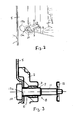
- Ein Ausführungsbeispiel der Erfindung ist in den Zeichnungen dargestellt und wird Im Folgenden näher beschrieben. Es zeigen
- Fig. 1
- eine perspektivische Ansicht des Gestells mit einem Ausschnitt in der Verkleidung,
- Fig. 2
- den vergrößerten Bereich A in
Fig. 1 , - Fig. 3
- einen Schnitt durch die Verkleidung und Stütze/Steg im Bereich einer Schraube.
- Zum Antrieb einer Pumpe ist an dieser ein Elektromotor über ein käfigförmiges Zwischengestell 1 befestigt, an dessen eine Seite die Pumpe und an dessen gegenüberliegenden Seite der Motor befestigt insbesondere angeflanscht ist. Ein solches Zwischengestell wird auch "Laterne" genannt und weist an einem Ende einen Befestigungsring (insbesondere mit Flansch) für die Pumpe und am gegenüberliegenden Ende einen Befestigungsring (insbesondere mit Flansch) für den Motor auf. Beide Ringe sind durch zueinander parallele Stützen bzw. Stege 2 insbesondere aus Kunststoff miteinander verbunden und im Innenraum des Gestells 1 verläuft eine Welle 3 insbesondere mit dazwischengeschalteter Kupplung 4. Die Welle 3 verbindet die Pumpenwelle mit der Motorenwelle.
- Das Gestell 1 ist außenseitig von einer flächigen Verkleidung 5 aus Blech oder Kunststoff rundum vollständig bedeckt, die an den Stützen/Stegen 2 angeschraubt und damit lösbar ist. An den Schraubstellen weisen die Stützen/Stege 2 Bohrungen 6 auf, in denen jeweils ein buchsenförmiger Einsatz 7 befestigt einliegt, vorzugsweise eingespritzt oder eingegossen oder mit selbstschneidendem Gewinde eingeschraubt. Der Einsatz 7 weist ein Innengewinde auf, in das die Schraube 8 mit ihrem Außengewinde 9 eingeschraubt ist.
- Die Schraube 8 besitzt an ihrem vorderen Ende einen Kopf 10 und im hinteren Bereich einen zylindrischen Bereich 11 ohne Gewinde und mit kleinerem Durchmesser als der des Außengewindes 9. Ferner ist am inneren Ende der Schraube 8 eine ringförmige Platte 12 als Erweiterung bzw. Stoppring befestigt, die einen größeren Außendurchmesser aufweist als der Innendurchmesser der Bohrung 6. Durch diese Konstruktion kann die Schraube 8 losgeschraubt werden, ohne im gelösten Zustand abzufallen. Hierbei weist der Bereich 11 eine axiale Länge auf, die vorzugsweise größer ist als die axiale Länge der Bohrung 6.
- Die Schraube 8 durchquert in der Verkleidung 5 eine Öffnung 13, die schlitzförmig ausgebildet ist. Die Schraube liegt in der schlitzförmigen Öffnung 13 der Verkleidung 5 ein, wobei die Öffnung einen ersten schmalen Bereich 13a aufweist, mit einer Breite kleiner als der Durchmesser des Schraubenkopfes 10 und einen zweiten breiteren insbesondere kreisförmigen Bereich 13b, mit einer Breite insbesondere einem Durchmesser gleich oder größer als der Durchmesser des Schraubenkopfes, um eine Renkverbindung zu bilden. Der erste schmale Bereich 13a der schlitzförmigen Öffnung der Verkleidung bildet eine Senke 14, in der der Schraubenkopf 10 versenkt einliegt.
- Im aufgeschraubten Zustand der Schraube 8 braucht die Verkleidung 5 mit ihrer Öffnung 13 nur so weit verschoben werden, dass der zweite Bereich 13b den Kopf 10 erreicht hat. Dann kann der Öffnungsbereich 13b über den Kopf 10 geschoben werden, um die Verkleidung 5 zu entfernen. Ein Wiederbefestigen der Verkleidung erfolgt in umgekehrter Reihenfolge.
Claims (10)
- Vorrichtung zwischen einer Pumpe und einem Elektromotor mit einer die Pumpenwelle und die Motorenwelle verbindenden Welle (3), wobei die Welle von einem Gestell (1) insbesondere einem Käfig bzw. einer Laterne umgeben sind, an dem zu einer Seite der Motor und auf der gegenüberliegenden Seite die Pumpe befestigt ist, wobei das Gestell außenseitig Stützen (1) insbesondere in Form von Stegen aufweist, die im Wesentlichen parallel zur Welle (3) verlaufen, und wobei das Gestell (1) außenseitig von mindestens einer Verkleidung (5) überdeckt ist, dadurch gekennzeichnet, dass die Verkleidung (5) an den Stützen/Stegen (2) durch Schrauben (8) lösbar befestigt ist, die im aufgeschraubten Zustand unlösbar an der Stütze/dem Steg gehalten sind.
- Vorrichtung nach Anspruch 1, dadurch gekennzeichnet, dass die Schrauben (8) an ihrem inneren Ende eine Erweiterung (12) aufweisen, um unverlierbar zu sein.
- Vorrichtung nach Anspruch 1 oder 2, dadurch gekennzeichnet, dass die Schrauben (8) im Innengewinde eines buchsenförmigen Einsatzes (7) eingeschraubt sind, die in einer Bohrung der Stütze/des Steges (2) einliegt.
- Vorrichtung nach einem der vorherigen Ansprüche, dadurch gekennzeichnet, dass die Schraube (8) mit einem inneren Bereich über den Einsatz (7) hinaus nach innen vorsteht.
- Vorrichtung nach Anspruch 4, dadurch gekennzeichnet, dass der innere Bereich (11) der Schraube (8) kein Gewinde aufweist und einen Außendurchmesser besitzt, der gleich oder geringer ist, als der Innendurchmesser des Gewindes des Einsatzes (7).
- Vorrichtung nach einem der vorherigen Ansprüche, dadurch gekennzeichnet, dass die Verkleidung (5) aus Blech oder Kunststoff besteht.
- Vorrichtung nach einem der vorherigen Ansprüche, dadurch gekennzeichnet, dass die Stützen/die Stege (2) aus Kunststoff bestehen.
- Vorrichtung nach einem der vorherigen Ansprüche, dadurch gekennzeichnet, dass die Schraube (8) in einer schlitzförmigen Öffnung (13) der Verkleidung (5) einliegt, wobei die Öffnung einen ersten schmalen Bereich (13a) aufweist, mit einer Breite kleiner als der Durchmesser des Schraubenkopfes (10), und einen zweiten breiteren insbesondere kreisförmigen Bereich (13b) aufweist, mit einer Breite insbesondere einem Durchmesser gleich oder größer als der Durchmesser des Schraubenkopfes (10).
- Vorrichtung nach Anspruch 8, dadurch gekennzeichnet, dass der erste schmale Bereich (13a) der schlitzförmigen Öffnung (13) der Verkleidung (5) eine Senke (14) bildet, in der der Schraubenkopf (10) versenkt einliegt.
- Vorrichtung nach einem der vorherigen Ansprüche, dadurch gekennzeichnet, dass die Welle (3) innerhalb des Gestells (1) eine Kupplung (4) aufweist.
Applications Claiming Priority (1)
| Application Number | Priority Date | Filing Date | Title |
|---|---|---|---|
| DE102009052155A DE102009052155A1 (de) | 2009-11-06 | 2009-11-06 | Vorrichtung zwischen Pumpe und Elektromotor |
Publications (3)
| Publication Number | Publication Date |
|---|---|
| EP2320089A2 true EP2320089A2 (de) | 2011-05-11 |
| EP2320089A3 EP2320089A3 (de) | 2014-08-06 |
| EP2320089B1 EP2320089B1 (de) | 2015-12-16 |
Family
ID=43216153
Family Applications (1)
| Application Number | Title | Priority Date | Filing Date |
|---|---|---|---|
| EP10009864.9A Active EP2320089B1 (de) | 2009-11-06 | 2010-09-17 | Vorrichtung zwischen Pumpe und Elektromotor |
Country Status (2)
| Country | Link |
|---|---|
| EP (1) | EP2320089B1 (de) |
| DE (1) | DE102009052155A1 (de) |
Cited By (1)
| Publication number | Priority date | Publication date | Assignee | Title |
|---|---|---|---|---|
| WO2022079144A1 (de) * | 2020-10-16 | 2022-04-21 | KSB SE & Co. KGaA | Laterne mit stegen |
Family Cites Families (4)
| Publication number | Priority date | Publication date | Assignee | Title |
|---|---|---|---|---|
| JPS57124110A (en) * | 1981-01-21 | 1982-08-02 | Nissan Motor | Slip out preventing equipment of bolt |
| US6398521B1 (en) * | 2001-01-30 | 2002-06-04 | Sta-Rite Industries, Inc. | Adapter for motor and fluid pump |
| ITVI20030116A1 (it) * | 2003-06-13 | 2004-12-14 | Calpeda A Spa | Lanterna di raccordo in pompe monoblocco e protezione per detta lanterna. |
| DE202006013530U1 (de) * | 2006-09-04 | 2008-01-24 | S-Fasteners Gmbh | Schraubbolzen mit Sicherungs-Haltescheibe |
-
2009
- 2009-11-06 DE DE102009052155A patent/DE102009052155A1/de not_active Withdrawn
-
2010
- 2010-09-17 EP EP10009864.9A patent/EP2320089B1/de active Active
Non-Patent Citations (1)
| Title |
|---|
| None |
Cited By (2)
| Publication number | Priority date | Publication date | Assignee | Title |
|---|---|---|---|---|
| WO2022079144A1 (de) * | 2020-10-16 | 2022-04-21 | KSB SE & Co. KGaA | Laterne mit stegen |
| US12270399B2 (en) | 2020-10-16 | 2025-04-08 | KSB SE & Co. KGaA | Coupling unit with connecting pieces |
Also Published As
| Publication number | Publication date |
|---|---|
| DE102009052155A1 (de) | 2011-05-12 |
| EP2320089A3 (de) | 2014-08-06 |
| EP2320089B1 (de) | 2015-12-16 |
Similar Documents
| Publication | Publication Date | Title |
|---|---|---|
| DE2836498A1 (de) | Nichtmetallische kette | |
| EP2477717B1 (de) | Filter für flüssige oder gasförmige medien | |
| EP3529504A1 (de) | Spannvorrichtung für seile und ketten, mit gewindespindel und ratscheneinheit | |
| EP3032093B1 (de) | Befestigungsvorrichtung zur befestigung eines rotorblattes an einer rotornabe einer windkraftanlage | |
| DE202008000982U1 (de) | Gewindeeinsatz und Fahrzeugteil | |
| DE102017217562A1 (de) | Lagerverschlussvorrichtung und Verfahren zu deren Betrieb | |
| DE102020112157A1 (de) | Formschlüssige Bauteilverbindung und Energieverzehrvorrichtung einer Schienenfahrzeugkupplung mit einer solchen Bauteilverbindung | |
| DE102013213514A1 (de) | Sicherungsvorrichtung zum Sichern einer Mutter gegen ungewolltes Losdrehen, sowie Lageranordnung einer Welle | |
| WO2020035602A1 (de) | Dämpfungselement mit gewindeabschnitt | |
| EP2320089B1 (de) | Vorrichtung zwischen Pumpe und Elektromotor | |
| DE102007058319B4 (de) | Schneckengewindeschelle | |
| EP3290552B1 (de) | Galettenwalze | |
| DE202008009273U1 (de) | Zugstabsystem | |
| DE102013000428A1 (de) | Flanschritzel und Herstellungsverfahren dafür sowie spielfreies Stirnrad damit | |
| DE102011118587A1 (de) | Zweifach konische Schraubverbindung | |
| DE2701637A1 (de) | Schmitzring fuer rotationsdruckwerke | |
| DE102015225337A1 (de) | Gewindeelement | |
| DE1027939B (de) | Sicherung fuer Verschraubungen | |
| DE10309792A1 (de) | Maschinenelement | |
| EP1258339A1 (de) | Faserverstärktes Kunststoffteil | |
| DE202011105266U1 (de) | Sicherungsscheibe | |
| EP2236843B1 (de) | Anordnung, bestehend aus einer Schraube sowie einer an der Schraube befestigten Verliersicherung | |
| DE102011001502A1 (de) | Bolzen zum Verbinden von Bauteilen, seine Verwendung und Verbindungsanordnung | |
| DE3623148C2 (de) | Kettenanschlußelement für den Untertagebetrieb | |
| EP3359825A1 (de) | Verbindungsvorrichtung zum starren verbinden eines ersten rohres mit einem zweiten rohr |
Legal Events
| Date | Code | Title | Description |
|---|---|---|---|
| PUAI | Public reference made under article 153(3) epc to a published international application that has entered the european phase |
Free format text: ORIGINAL CODE: 0009012 |
|
| AK | Designated contracting states |
Kind code of ref document: A2 Designated state(s): AL AT BE BG CH CY CZ DE DK EE ES FI FR GB GR HR HU IE IS IT LI LT LU LV MC MK MT NL NO PL PT RO SE SI SK SM TR |
|
| AX | Request for extension of the european patent |
Extension state: BA ME RS |
|
| PUAL | Search report despatched |
Free format text: ORIGINAL CODE: 0009013 |
|
| AK | Designated contracting states |
Kind code of ref document: A3 Designated state(s): AL AT BE BG CH CY CZ DE DK EE ES FI FR GB GR HR HU IE IS IT LI LT LU LV MC MK MT NL NO PL PT RO SE SI SK SM TR |
|
| AX | Request for extension of the european patent |
Extension state: BA ME RS |
|
| RIC1 | Information provided on ipc code assigned before grant |
Ipc: F04D 13/02 20060101AFI20140701BHEP |
|
| 17P | Request for examination filed |
Effective date: 20140814 |
|
| RBV | Designated contracting states (corrected) |
Designated state(s): AL AT BE BG CH CY CZ DE DK EE ES FI FR GB GR HR HU IE IS IT LI LT LU LV MC MK MT NL NO PL PT RO SE SI SK SM TR |
|
| GRAP | Despatch of communication of intention to grant a patent |
Free format text: ORIGINAL CODE: EPIDOSNIGR1 |
|
| INTG | Intention to grant announced |
Effective date: 20150624 |
|
| GRAS | Grant fee paid |
Free format text: ORIGINAL CODE: EPIDOSNIGR3 |
|
| GRAA | (expected) grant |
Free format text: ORIGINAL CODE: 0009210 |
|
| AK | Designated contracting states |
Kind code of ref document: B1 Designated state(s): AL AT BE BG CH CY CZ DE DK EE ES FI FR GB GR HR HU IE IS IT LI LT LU LV MC MK MT NL NO PL PT RO SE SI SK SM TR |
|
| REG | Reference to a national code |
Ref country code: GB Ref legal event code: FG4D Free format text: NOT ENGLISH |
|
| REG | Reference to a national code |
Ref country code: CH Ref legal event code: EP |
|
| REG | Reference to a national code |
Ref country code: IE Ref legal event code: FG4D Free format text: LANGUAGE OF EP DOCUMENT: GERMAN |
|
| REG | Reference to a national code |
Ref country code: AT Ref legal event code: REF Ref document number: 765694 Country of ref document: AT Kind code of ref document: T Effective date: 20160115 |
|
| REG | Reference to a national code |
Ref country code: DE Ref legal event code: R096 Ref document number: 502010010764 Country of ref document: DE |
|
| REG | Reference to a national code |
Ref country code: NL Ref legal event code: MP Effective date: 20151216 |
|
| REG | Reference to a national code |
Ref country code: LT Ref legal event code: MG4D |
|
| PG25 | Lapsed in a contracting state [announced via postgrant information from national office to epo] |
Ref country code: LT Free format text: LAPSE BECAUSE OF FAILURE TO SUBMIT A TRANSLATION OF THE DESCRIPTION OR TO PAY THE FEE WITHIN THE PRESCRIBED TIME-LIMIT Effective date: 20151216 Ref country code: NO Free format text: LAPSE BECAUSE OF FAILURE TO SUBMIT A TRANSLATION OF THE DESCRIPTION OR TO PAY THE FEE WITHIN THE PRESCRIBED TIME-LIMIT Effective date: 20160316 Ref country code: HR Free format text: LAPSE BECAUSE OF FAILURE TO SUBMIT A TRANSLATION OF THE DESCRIPTION OR TO PAY THE FEE WITHIN THE PRESCRIBED TIME-LIMIT Effective date: 20151216 |
|
| PG25 | Lapsed in a contracting state [announced via postgrant information from national office to epo] |
Ref country code: SE Free format text: LAPSE BECAUSE OF FAILURE TO SUBMIT A TRANSLATION OF THE DESCRIPTION OR TO PAY THE FEE WITHIN THE PRESCRIBED TIME-LIMIT Effective date: 20151216 Ref country code: LV Free format text: LAPSE BECAUSE OF FAILURE TO SUBMIT A TRANSLATION OF THE DESCRIPTION OR TO PAY THE FEE WITHIN THE PRESCRIBED TIME-LIMIT Effective date: 20151216 Ref country code: FI Free format text: LAPSE BECAUSE OF FAILURE TO SUBMIT A TRANSLATION OF THE DESCRIPTION OR TO PAY THE FEE WITHIN THE PRESCRIBED TIME-LIMIT Effective date: 20151216 Ref country code: GR Free format text: LAPSE BECAUSE OF FAILURE TO SUBMIT A TRANSLATION OF THE DESCRIPTION OR TO PAY THE FEE WITHIN THE PRESCRIBED TIME-LIMIT Effective date: 20160317 Ref country code: NL Free format text: LAPSE BECAUSE OF FAILURE TO SUBMIT A TRANSLATION OF THE DESCRIPTION OR TO PAY THE FEE WITHIN THE PRESCRIBED TIME-LIMIT Effective date: 20151216 |
|
| PG25 | Lapsed in a contracting state [announced via postgrant information from national office to epo] |
Ref country code: CZ Free format text: LAPSE BECAUSE OF FAILURE TO SUBMIT A TRANSLATION OF THE DESCRIPTION OR TO PAY THE FEE WITHIN THE PRESCRIBED TIME-LIMIT Effective date: 20151216 Ref country code: ES Free format text: LAPSE BECAUSE OF FAILURE TO SUBMIT A TRANSLATION OF THE DESCRIPTION OR TO PAY THE FEE WITHIN THE PRESCRIBED TIME-LIMIT Effective date: 20151216 |
|
| REG | Reference to a national code |
Ref country code: FR Ref legal event code: PLFP Year of fee payment: 7 |
|
| PG25 | Lapsed in a contracting state [announced via postgrant information from national office to epo] |
Ref country code: RO Free format text: LAPSE BECAUSE OF FAILURE TO SUBMIT A TRANSLATION OF THE DESCRIPTION OR TO PAY THE FEE WITHIN THE PRESCRIBED TIME-LIMIT Effective date: 20151216 Ref country code: SK Free format text: LAPSE BECAUSE OF FAILURE TO SUBMIT A TRANSLATION OF THE DESCRIPTION OR TO PAY THE FEE WITHIN THE PRESCRIBED TIME-LIMIT Effective date: 20151216 Ref country code: PT Free format text: LAPSE BECAUSE OF FAILURE TO SUBMIT A TRANSLATION OF THE DESCRIPTION OR TO PAY THE FEE WITHIN THE PRESCRIBED TIME-LIMIT Effective date: 20160418 Ref country code: SM Free format text: LAPSE BECAUSE OF FAILURE TO SUBMIT A TRANSLATION OF THE DESCRIPTION OR TO PAY THE FEE WITHIN THE PRESCRIBED TIME-LIMIT Effective date: 20151216 Ref country code: EE Free format text: LAPSE BECAUSE OF FAILURE TO SUBMIT A TRANSLATION OF THE DESCRIPTION OR TO PAY THE FEE WITHIN THE PRESCRIBED TIME-LIMIT Effective date: 20151216 Ref country code: IS Free format text: LAPSE BECAUSE OF FAILURE TO SUBMIT A TRANSLATION OF THE DESCRIPTION OR TO PAY THE FEE WITHIN THE PRESCRIBED TIME-LIMIT Effective date: 20160416 |
|
| REG | Reference to a national code |
Ref country code: DE Ref legal event code: R097 Ref document number: 502010010764 Country of ref document: DE |
|
| PLBE | No opposition filed within time limit |
Free format text: ORIGINAL CODE: 0009261 |
|
| STAA | Information on the status of an ep patent application or granted ep patent |
Free format text: STATUS: NO OPPOSITION FILED WITHIN TIME LIMIT |
|
| PG25 | Lapsed in a contracting state [announced via postgrant information from national office to epo] |
Ref country code: DK Free format text: LAPSE BECAUSE OF FAILURE TO SUBMIT A TRANSLATION OF THE DESCRIPTION OR TO PAY THE FEE WITHIN THE PRESCRIBED TIME-LIMIT Effective date: 20151216 Ref country code: PL Free format text: LAPSE BECAUSE OF FAILURE TO SUBMIT A TRANSLATION OF THE DESCRIPTION OR TO PAY THE FEE WITHIN THE PRESCRIBED TIME-LIMIT Effective date: 20151216 |
|
| 26N | No opposition filed |
Effective date: 20160919 |
|
| PG25 | Lapsed in a contracting state [announced via postgrant information from national office to epo] |
Ref country code: BE Free format text: LAPSE BECAUSE OF NON-PAYMENT OF DUE FEES Effective date: 20160930 Ref country code: SI Free format text: LAPSE BECAUSE OF FAILURE TO SUBMIT A TRANSLATION OF THE DESCRIPTION OR TO PAY THE FEE WITHIN THE PRESCRIBED TIME-LIMIT Effective date: 20151216 |
|
| PG25 | Lapsed in a contracting state [announced via postgrant information from national office to epo] |
Ref country code: MC Free format text: LAPSE BECAUSE OF FAILURE TO SUBMIT A TRANSLATION OF THE DESCRIPTION OR TO PAY THE FEE WITHIN THE PRESCRIBED TIME-LIMIT Effective date: 20151216 |
|
| REG | Reference to a national code |
Ref country code: CH Ref legal event code: PL |
|
| REG | Reference to a national code |
Ref country code: IE Ref legal event code: MM4A |
|
| PG25 | Lapsed in a contracting state [announced via postgrant information from national office to epo] |
Ref country code: IE Free format text: LAPSE BECAUSE OF NON-PAYMENT OF DUE FEES Effective date: 20160917 Ref country code: LI Free format text: LAPSE BECAUSE OF NON-PAYMENT OF DUE FEES Effective date: 20160930 Ref country code: CH Free format text: LAPSE BECAUSE OF NON-PAYMENT OF DUE FEES Effective date: 20160930 |
|
| REG | Reference to a national code |
Ref country code: FR Ref legal event code: PLFP Year of fee payment: 8 |
|
| PG25 | Lapsed in a contracting state [announced via postgrant information from national office to epo] |
Ref country code: LU Free format text: LAPSE BECAUSE OF NON-PAYMENT OF DUE FEES Effective date: 20160917 |
|
| REG | Reference to a national code |
Ref country code: AT Ref legal event code: MM01 Ref document number: 765694 Country of ref document: AT Kind code of ref document: T Effective date: 20160917 |
|
| REG | Reference to a national code |
Ref country code: BE Ref legal event code: MM Effective date: 20160930 |
|
| PG25 | Lapsed in a contracting state [announced via postgrant information from national office to epo] |
Ref country code: AT Free format text: LAPSE BECAUSE OF NON-PAYMENT OF DUE FEES Effective date: 20160917 |
|
| PG25 | Lapsed in a contracting state [announced via postgrant information from national office to epo] |
Ref country code: CY Free format text: LAPSE BECAUSE OF FAILURE TO SUBMIT A TRANSLATION OF THE DESCRIPTION OR TO PAY THE FEE WITHIN THE PRESCRIBED TIME-LIMIT Effective date: 20151216 Ref country code: HU Free format text: LAPSE BECAUSE OF FAILURE TO SUBMIT A TRANSLATION OF THE DESCRIPTION OR TO PAY THE FEE WITHIN THE PRESCRIBED TIME-LIMIT; INVALID AB INITIO Effective date: 20100917 |
|
| PG25 | Lapsed in a contracting state [announced via postgrant information from national office to epo] |
Ref country code: MT Free format text: LAPSE BECAUSE OF FAILURE TO SUBMIT A TRANSLATION OF THE DESCRIPTION OR TO PAY THE FEE WITHIN THE PRESCRIBED TIME-LIMIT Effective date: 20151216 Ref country code: MK Free format text: LAPSE BECAUSE OF FAILURE TO SUBMIT A TRANSLATION OF THE DESCRIPTION OR TO PAY THE FEE WITHIN THE PRESCRIBED TIME-LIMIT Effective date: 20151216 Ref country code: TR Free format text: LAPSE BECAUSE OF FAILURE TO SUBMIT A TRANSLATION OF THE DESCRIPTION OR TO PAY THE FEE WITHIN THE PRESCRIBED TIME-LIMIT Effective date: 20151216 |
|
| PG25 | Lapsed in a contracting state [announced via postgrant information from national office to epo] |
Ref country code: BG Free format text: LAPSE BECAUSE OF FAILURE TO SUBMIT A TRANSLATION OF THE DESCRIPTION OR TO PAY THE FEE WITHIN THE PRESCRIBED TIME-LIMIT Effective date: 20151216 |
|
| REG | Reference to a national code |
Ref country code: FR Ref legal event code: PLFP Year of fee payment: 9 |
|
| PG25 | Lapsed in a contracting state [announced via postgrant information from national office to epo] |
Ref country code: AL Free format text: LAPSE BECAUSE OF FAILURE TO SUBMIT A TRANSLATION OF THE DESCRIPTION OR TO PAY THE FEE WITHIN THE PRESCRIBED TIME-LIMIT Effective date: 20151216 |
|
| P01 | Opt-out of the competence of the unified patent court (upc) registered |
Effective date: 20230615 |
|
| REG | Reference to a national code |
Ref country code: DE Ref legal event code: R084 Ref document number: 502010010764 Country of ref document: DE |
|
| PGFP | Annual fee paid to national office [announced via postgrant information from national office to epo] |
Ref country code: DE Payment date: 20250820 Year of fee payment: 16 |
|
| PGFP | Annual fee paid to national office [announced via postgrant information from national office to epo] |
Ref country code: IT Payment date: 20250820 Year of fee payment: 16 |
|
| PGFP | Annual fee paid to national office [announced via postgrant information from national office to epo] |
Ref country code: GB Payment date: 20250822 Year of fee payment: 16 |
|
| PGFP | Annual fee paid to national office [announced via postgrant information from national office to epo] |
Ref country code: FR Payment date: 20250820 Year of fee payment: 16 |