EP2320046A2 - Thermoelektrisches Generatorenmodul und abgasführendes Bauteil - Google Patents
Thermoelektrisches Generatorenmodul und abgasführendes Bauteil Download PDFInfo
- Publication number
- EP2320046A2 EP2320046A2 EP10013482A EP10013482A EP2320046A2 EP 2320046 A2 EP2320046 A2 EP 2320046A2 EP 10013482 A EP10013482 A EP 10013482A EP 10013482 A EP10013482 A EP 10013482A EP 2320046 A2 EP2320046 A2 EP 2320046A2
- Authority
- EP
- European Patent Office
- Prior art keywords
- thermoelectric generator
- exhaust gas
- exhaust
- generator module
- carrying component
- Prior art date
- Legal status (The legal status is an assumption and is not a legal conclusion. Google has not performed a legal analysis and makes no representation as to the accuracy of the status listed.)
- Withdrawn
Links
Images

Classifications
-
- F—MECHANICAL ENGINEERING; LIGHTING; HEATING; WEAPONS; BLASTING
- F01—MACHINES OR ENGINES IN GENERAL; ENGINE PLANTS IN GENERAL; STEAM ENGINES
- F01N—GAS-FLOW SILENCERS OR EXHAUST APPARATUS FOR MACHINES OR ENGINES IN GENERAL; GAS-FLOW SILENCERS OR EXHAUST APPARATUS FOR INTERNAL-COMBUSTION ENGINES
- F01N5/00—Exhaust or silencing apparatus combined or associated with devices profiting by exhaust energy
- F01N5/02—Exhaust or silencing apparatus combined or associated with devices profiting by exhaust energy the devices using heat
- F01N5/025—Exhaust or silencing apparatus combined or associated with devices profiting by exhaust energy the devices using heat the device being thermoelectric generators
-
- H—ELECTRICITY
- H10—SEMICONDUCTOR DEVICES; ELECTRIC SOLID-STATE DEVICES NOT OTHERWISE PROVIDED FOR
- H10N—ELECTRIC SOLID-STATE DEVICES NOT OTHERWISE PROVIDED FOR
- H10N10/00—Thermoelectric devices comprising a junction of dissimilar materials, i.e. devices exhibiting Seebeck or Peltier effects
- H10N10/10—Thermoelectric devices comprising a junction of dissimilar materials, i.e. devices exhibiting Seebeck or Peltier effects operating with only the Peltier or Seebeck effects
- H10N10/13—Thermoelectric devices comprising a junction of dissimilar materials, i.e. devices exhibiting Seebeck or Peltier effects operating with only the Peltier or Seebeck effects characterised by the heat-exchanging means at the junction
-
- F—MECHANICAL ENGINEERING; LIGHTING; HEATING; WEAPONS; BLASTING
- F01—MACHINES OR ENGINES IN GENERAL; ENGINE PLANTS IN GENERAL; STEAM ENGINES
- F01N—GAS-FLOW SILENCERS OR EXHAUST APPARATUS FOR MACHINES OR ENGINES IN GENERAL; GAS-FLOW SILENCERS OR EXHAUST APPARATUS FOR INTERNAL-COMBUSTION ENGINES
- F01N2240/00—Combination or association of two or more different exhaust treating devices, or of at least one such device with an auxiliary device, not covered by indexing codes F01N2230/00 or F01N2250/00, one of the devices being
- F01N2240/04—Combination or association of two or more different exhaust treating devices, or of at least one such device with an auxiliary device, not covered by indexing codes F01N2230/00 or F01N2250/00, one of the devices being an electric, e.g. electrostatic, device other than a heater
-
- Y—GENERAL TAGGING OF NEW TECHNOLOGICAL DEVELOPMENTS; GENERAL TAGGING OF CROSS-SECTIONAL TECHNOLOGIES SPANNING OVER SEVERAL SECTIONS OF THE IPC; TECHNICAL SUBJECTS COVERED BY FORMER USPC CROSS-REFERENCE ART COLLECTIONS [XRACs] AND DIGESTS
- Y02—TECHNOLOGIES OR APPLICATIONS FOR MITIGATION OR ADAPTATION AGAINST CLIMATE CHANGE
- Y02T—CLIMATE CHANGE MITIGATION TECHNOLOGIES RELATED TO TRANSPORTATION
- Y02T10/00—Road transport of goods or passengers
- Y02T10/10—Internal combustion engine [ICE] based vehicles
- Y02T10/12—Improving ICE efficiencies
Definitions
- thermoelectric generator module for arrangement in an exhaust gas-carrying component in an exhaust system of a motor vehicle, wherein the thermoelectric generator module has a hot side and a cold side, and a motor vehicle exhaust system with a component carrying exhaust gas.
- thermoelectric generators are arranged in an exhaust path of an internal combustion engine in order to recover energy from the exhaust heat entrained by the exhaust gases.
- thermoelectric generator Due to the exhaust gas flow and the connection of the thermoelectric generator to the environment creates a temperature difference. So that a temperature difference can occur at the thermoelectric generator, it has a hot side and a cold side.
- Thermoelectric generators use the Seebeck effect to convert the temperature difference into electrical energy.
- thermoelectric generator In the construction of a thermoelectric generator, a thin-film technology or a film technology is usually used, which however can not work optimally in an exhaust gas line in which high temperature differences prevail. In order for a temperature difference in the operation of the thermoelectric generator can be maintained, a corresponding thickness of the thermoelectric generator is necessary.
- thermoelectric generator In order to avoid an electrical short circuit and to achieve mechanical stability, the top and bottom of the thermoelectric generator is fixed by means of ceramic plates. Through the ceramic plates, a hot side is formed on the side of the thermoelectric generator facing the exhaust line, and a cold side is formed on the side remote from the exhaust line.
- the heat energy contained in the exhaust system is strongly dependent on the individual operating points of the engine during operation of a motor vehicle. So it comes here at low load points of the engine to an exhaust gas temperature at the thermoelectric generator modules of about 200 ° C to 300 ° C, at a high load point of the internal combustion engine to a temperature of about 600 ° C to 800 ° C.
- the object of the present invention is therefore to increase the efficiency of energy recovery from automotive exhaust gases and to provide a thermoelectric generator module that ensures a sufficiently high temperature difference at different temperature conditions, so that an electrical energy is always ensured by the thermoelectric generator module.
- thermoelectric generator module has a cover plate on the hot side.
- thermoelectric generator modules are arranged by a heatsink on a component carrying exhaust gas with inserted thermoelectric generator modules.
- the inventive approach of the end plate on the hot side of the thermoelectric generator module ensures a particularly good heat transfer into the thermoelectric generator module.
- the end plate should advantageously consist of a good thermal conductivity of metallic material. This material should also be adapted to the environments in an exhaust line, for example with respect to its corrosion behavior.
- thermoelectric generator module can be arranged with the end plate in contact with a fluid flow of the exhaust gas.
- thermoelectric generator module can be prefabricated with the end plate in a separate production line and then can be arranged directly in the exhaust gas component.
- the end plate enters into direct contact with the exhaust gas line and can thus extract heat from the fluid flow of the exhaust gas. It is advantageously made of a metallic material.
- the surface of the end plate has a rib structure. Due to the rib structure, the surface of the end plate increases, with the same space requirement for a location of the thermoelectric generator module. With a Enlarged surface, the thermoelectric generator module is possible to withdraw more heat from the fluid flow, so that at different temperatures of the exhaust gas always a sufficient temperature difference is ensured for operation of the thermoelectric generator module.
- the rib structure can also be formed in that the end plate is profiled at least in certain areas.
- the rib structure is designed for the flow guidance of the fluid flow.
- forced convection takes place on the surface of the end plate.
- This can for example be adapted to the exhaust gas flow of a gasoline or diesel engine, since there are differences in the flow velocity and also in the exhaust gas temperature.
- thermoelectric generator module can be used with the end plate in a recess of the exhaust gas-carrying component.
- the exhaust gas-carrying component is designed to be similar to a muffler in an exhaust system.
- An arrangement in conventionally planned Karrosserietunneln a vehicle body for receiving exhaust strands is thus feasible.
- the exhaust-gas-conducting component formed in this way has recesses for receiving the thermoelectric generator module.
- the thermoelectric generator module can be used in this recess and positively, positively or materially connected to the exhaust gas-carrying component to a motor vehicle exhaust heat recovery system.
- the end plate is in its dimensions almost identical to the recess of the exhaust gas leading component. It can be pressed by a fit in the recess. In another Embodiment variant, the end plate but also be larger than the recess so that it covers these in the edge areas.
- thermoelectric generator modules are arranged in a component carrying exhaust gas.
- the thermoelectric generator modules can be arranged, for example, on the top and on the underside of the exhaust gas-carrying component or completely on the other side.
- the exhaust system is effectively removed in a space-saving design heat because optimal use of space is formed by a high density of thermoelectric generator modules on a component carrying exhaust gas.
- thermoelectric generator modules heatsink in a motor vehicle exhaust system are arranged on the exhaust gas-carrying component with inserted thermoelectric generator modules heatsink.
- thermoelectric generator modules heatsink offers the particular advantage that an optimal temperature difference can be generated in the thermoelectric generator modules by the heat sinks at each operating point. Also, the construction thus produced space-saving for the arrangement under a motor vehicle.
- at least two exhaust-gas-carrying components are arranged one above the other in layers with heat sinks.
- the exhaust gas carrying component is made of a tube by means of hydroforming. This offers a particularly inexpensive and simple production variant of the exhaust gas-carrying component.
- the exhaust gas-carrying component is manufactured by shell construction.
- a particularly inexpensive production variant of the exhaust gas-carrying component is realized depending on the design.
- the recesses for receiving the thermoelectric generator modules are made in the exhaust gas-carrying components by punching.
- the recess can be produced by a punching process.
- the punching process is characterized by a high degree of accuracy.
- the thermoelectric generator module can be inserted into a respective recess by means of non-positive, positive or cohesive connection.
- the dimensional stability is particularly high due to the punching process on the finished molded component.
- the connection can be realized by welding, soldering, press fit or gluing.
- FIG. 1 shows an exhaust gas-carrying component 2.
- the exhaust gas-carrying component 2 has an outer shape similar to a muffler in an exhaust line 3 of a motor vehicle.
- the exhaust gas-carrying component 2 is in the exhaust line. 3 a motor vehicle integrated.
- the thermoelectric generator modules 1 are arranged on the exhaust-gas-conducting component 2, through which a fluid flow 4 flows.
- FIG. 2 shows a thermoelectric generator module 1.
- the thermoelectric generator module 1 has a hot side 5 and a cold side 6. In the arrangement in the exhaust-gas-conducting component 2, the hot side 5 is directed toward the interior of the exhaust-gas-conducting component 2, the cold side 6 to the exterior of the exhaust-gas-carrying component 2.
- the thermoelectric generator module 1 also has a cover plate 7.
- the end plate 7 is arranged on the hot side 5 of the thermoelectric generator module 1.
- the thermoelectric generator module 1 is aligned with its end plate 7 to a fluid flow 4 in the interior of the exhaust gas-carrying component 2 out. In this case, over the surface of the end plate 7, a forced convection and thereby a heat exchange between the fluid flow 4 of the exhaust gas and end plate 7.
- the heat transfer thus generated arise on the thermoelectric generator module 1, the aforementioned hot side 5 and the complementary cold side 6.
- the surface of the end plate 7 has a rib structure.
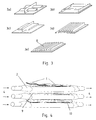
- FIG. 3 shows various embodiments in the FIGS. 3a to 3e the fin structure of the end plate 7.
- the FIGS. 3a to 3c are specifically used for flow guidance and generate depending on the flow velocity, a linear or turbulent flow on the surface of the end plate 7.
- the embodiments of the Figures 3d and 3e are, however, inexpensive to produce. The flow behavior is significantly dependent on the flow velocity over the rib-like surface 8.
- FIG. 4 shows a motor vehicle exhaust system with exhaust-carrying components 2, which thermoelectric generator modules 1 have.
- the Exhaust gas carrying components 2 have for receiving the thermoelectric generator modules 1 recesses 9. In these recesses 9, the thermoelectric generator modules 1 are used.
- the insert can be realized by a press fit, but also by gluing or soldering or welding.
- the arrangement further has heat sinks 10.
- the heat sink 10 are arranged in layers with the exhaust-gas-carrying components 2 one above the other or side by side. Heat contained in the fluid stream 4 of the exhaust gas can thus be transmitted via forced convection to the end plate 7, and voltage is generated between the hot and cold side 5, 6 of the thermoelectric generator module 1 by means of the Seebeck effect.
Landscapes
- Engineering & Computer Science (AREA)
- Chemical & Material Sciences (AREA)
- Combustion & Propulsion (AREA)
- Mechanical Engineering (AREA)
- General Engineering & Computer Science (AREA)
- Exhaust Silencers (AREA)
- Air-Conditioning For Vehicles (AREA)
- Cooling, Air Intake And Gas Exhaust, And Fuel Tank Arrangements In Propulsion Units (AREA)
Abstract
Description
- Die vorliegende Erfindung betrifft ein thermoelektrisches Generatorenmodul zur Anordnung in einem abgasführenden Bauteil in einem Abgasstrang eines Kraftfahrzeuges, wobei das thermoelektrische Generatorenmodul eine Heißseite und eine Kaltseite aufweist, sowie ein Kraftfahrzeug-Abgassystem mit einem abgasführenden Bauteil.
- Aus dem Stand der Technik sind Abgaswärmerückgewinnungssysteme bekannt. Hierbei werden thermoelektrische Generatoren in einem Abgasweg eines Verbrennungsmotors angeordnet, um Energie aus der von den Abgasen mitgeführten Abgaswärme zurückzugewinnen.
- Durch den Abgasstrom und die Verbindung des thermoelektrischen Generators zur Umgebung entsteht eine Temperaturdifferenz. Damit an dem thermoelektrischen Generator eine Temperaturdifferenz auftreten kann, verfügt dieser über eine Heiß- und über eine Kaltseite.
- Thermoelektrische Generatoren wandeln mit Hilfe des Seebeck-Effektes die vorliegende Temperaturdifferenz in elektrische Energie um.
- Im Aufbau eines thermoelektrischen Generators wird meistens eine Dünnschichttechnologie oder eine Folientechnik eingesetzt, die jedoch in einem Abgasstrang, in dem hohe Temperaturdifferenzen herrschen, nicht optimal arbeiten kann. Damit eine Temperaturdifferenz im Betrieb des thermoelektrischen Generators gehalten werden kann, ist eine entsprechende Dicke des thermoelektrischen Generators notwendig.
- Um einen elektrischen Kurzschluss zu vermeiden und mechanische Stabilität zu realisieren, wird die Ober- und Unterseite des thermoelektrischen Generators mit Hilfe von keramischen Platten fixiert. Durch die keramischen Platten werden auf der zum Abgasstrang hin gewandten Seite des thermoelektrischen Generators eine Heißseite und auf der dem Abgasstrang abgewandten Seite eine Kaltseite gebildet.
- Die im Abgasstrang enthaltene Wärmeenergie ist jedoch im Betrieb eines Kraftfahrzeugs stark von den einzelnen Betriebspunkten des Motors abhängig. So kommt es hier bei niedrigen Lastpunkten des Motors zu einer Abgastemperatur an den thermoelektrischen Generatorenmodulen von ca. 200 °C bis 300 °C, bei einem hohen Lastpunkt des Verbrennungsmotors zu einer Temperatur von ca. 600 °C bis 800 °C.
- Aufgabe der vorliegenden Erfindung ist es daher, die Effizienz der Energierückgewinnung aus Kraftfahrzeugabgasen zu steigern und ein thermoelektrisches Generatorenmodul zur Verfügung zu stellen, das bei verschiedenen Temperaturverhältnissen eine ausreichend hohe Temperaturdifferenz gewährleistet, so dass stets eine elektrische Energiegewinnung durch das thermoelektrische Generatorenmodul sichergestellt ist.
- Die Aufgabe wird gemäß den Merkmalen des Patentanspruchs 1 dadurch gelöst, dass das thermoelektrische Generatorenmodul an der Heißseite ein Abschlussblech aufweist.
- Die Aufgabe wird weiterhin durch ein Kraftfahrzeug-Abgassystem gemäß Patentanspruch 10 gelöst, indem an einem abgasführenden Bauteil mit eingesetzten thermoelektrischen Generatorenmodulen Kühlkörper angeordnet sind.
- Vorteilhafte Ausgestaltungen und Weiterbildungen des grundsätzlichen Erfindungsgedankens sind Gegenstand der abhängigen Ansprüche 2 bis 9 und 11.
- Durch den erfindungsgemäßen Lösungsansatz des Abschlussbleches an der Heißseite des thermoelektrischen Generatorenmoduls wird ein besonders guter Wärmeübergang in das thermoelektrische Generatorenmodul sichergestellt. Das Abschlussblech sollte dazu vorteilhaft aus einem gut wärmeleitenden metallischen Werkstoff bestehen. Dieser Werkstoff sollte ebenfalls an die Umgebungen in einem Abgasstrang angepasst sein, beispielsweise in Bezug auf sein Korrosionsverhalten.
- Vorzugsweise ist das thermoelektrische Generatorenmodul mit dem Abschlussblech in Kontakt mit einem Fluidstrom des Abgases anordnenbar. Dies bietet den Vorteil, dass das thermoelektrische Generatorenmodul mit dem Abschlussblech in einer separaten Produktionslinie vorgefertigt werden kann und dann direkt in dem abgasführenden Bauteil anordnenbar ist. Das Abschlussblech tritt dabei in direkten Kontakt mit dem Abgasstrang und kann somit dem Fluidstrom des Abgases Wärme entziehen. Es ist dabei vorteilhaft aus einem metallischen Werkstoff hergestellt.
- In einer bevorzugten Ausführungsform weist die Oberfläche des Abschlussbleches eine Rippenstruktur auf. Durch die Rippenstruktur vergrößert sich die Oberfläche des Abschlussbleches, bei gleich bleibendem Platzbedarf für einen Einbauort des thermoelektrischen Generatorenmoduls. Mit einer vergrößerten Oberfläche ist es dem thermoelektrischen Generatorenmodul möglich, dem Fluidstrom mehr Wärme zu entziehen, so dass bei verschiedenen Temperaturen des Abgases stets eine ausreichende Temperaturdifferenz, für einen Betrieb des thermoelektrischen Generatorenmoduls sichergestellt wird. Die Rippenstruktur kann auch dadurch ausgebildet sein, dass das Abschlussblech zumindest bereichsweise profiliert ist.
- Vorzugsweise ist die Rippenstruktur zur Strömungslenkung des Fluidstroms ausgebildet. Durch die Strömungslenkung erfolgt eine erzwungene Konvektion an der Oberfläche des Abschlussbleches. Mit erzwungener Konvektion kann je nach Strömungslenkung und Abgasströmungsgeschwindigkeit eine für den entsprechenden Anwendungsfall optimale Energierückgewinnung erfolgen. Diese kann zum Beispiel angepasst sein an die Abgasströmung eines Otto- oder Dieselmotors, da hier Unterschiede in der Strömungsgeschwindigkeit und auch in der Abgastemperatur bestehen.
- Besonders bevorzugt ist das thermoelektrische Generatorenmodul mit dem Abschlussblech in einer Aussparung des abgasführenden Bauteils einsetzbar. Dies bietet den Vorteil, dass das abgasführende Bauteil einem Schalldämpfer in einem Abgasstrang ähnlich ausgebildet ist. Eine Anordnung in konventionell geplanten Karrosserietunneln einer Fahrzeugkarosserie zur Aufnahme von Abgassträngen ist damit realisierbar.
- Das so ausgebildete abgasführende Bauteil weist Aussparungen zur Aufnahme des thermoelektrischen Generatorenmoduls auf. Das thermoelektrische Generatorenmodul kann in diese Aussparung eingesetzt werden und kraftschlüssig, formschlüssig oder stoffschlüssig mit dem abgasführenden Bauteil zu einem Kraftfahrzeug-Abgaswärmerückgewinnungssystem verbunden werden. Das Abschlussblech ist dabei in seinen Abmessungen nahezu identisch mit der Aussparung des abgasführenden Bauteils. Es kann durch eine Passung in die Aussparung eingepresst werden. In einer anderen Ausführungsvariante kann das Abschlussblech aber auch größer sein als die Aussparung, so dass es diese in den Randbereichen überdeckt.
- Vorzugsweise sind mehrere thermoelektrische Generatorenmodule in einem abgasführenden Bauteil angeordnet. Hierdurch kann in einer Kosten sparenden Bauteilanordnung ein hohes Energierückgewinnungspotential realisiert werden. Die thermoelektrischen Generatorenmodule können beispielsweise an der Ober- und an der Unterseite des abgasführenden Bauteils bzw. komplett umseitig angeordnet werden. Dem Abgasstrang wird so in platzsparender Bauweise effektiv Wärme entzogen, da eine optimale Raumnutzung durch eine hohe Dichte von thermoelektrischen Generatorenmodulen an einem abgasführenden Bauteil ausgebildet ist.
- In einer besonders bevorzugten Ausführungsvariante sind bei einem Kraftfahrzeug Abgassystem an dem abgasführenden Bauteil mit eingesetzten thermoelektrischen Generatorenmodulen Kühlkörper angeordnet. Dies bietet insbesondere den Vorteil, dass durch die Kühlkörper in jedem Betriebspunkt eine optimale Temperaturdifferenz in den thermoelektrischen Generatorenmodulen erzeugt werden kann. Ebenfalls ist die so hergestellte Bauweise Platz sparend für die Anordnung unter einem Kraftfahrzeug. In einer weiteren Ausführungsform der vorliegenden Erfindung sind mindestens zwei abgasführende Bauteile schichtweise mit Kühlkörpern übereinander angeordnet.
- Vorzugsweise ist das abgasführende Bauteil aus einem Rohr mittels Innenhochdruckumformung hergestellt. Dies bietet eine besonders preisgünstige und einfache Herstellungsvariante des abgasführenden Bauteils.
- In einer weiteren vorteilhaften Ausführungsform ist das abgasführende Bauteil durch Schalenbauweise hergestellt. Auch hier wird je nach Bauform eine besonders preisgünstige Produktionsvariante des abgasführenden Bauteils realisiert.
- Von Vorteil ist es, wenn die Aussparungen zur Aufnahme der thermoelektrischen Generatorenmodule in die abgasführenden Bauteile durch Ausstanzen hergestellt sind. Bei dem fertig geformten abgasführenden Bauteil kann somit die Aussparung durch einen Ausstanzprozess hergestellt werden. Der Ausstanzprozess zeichnet sich durch eine hohe Genauigkeit aus. Je nach Anwendungsgebiet kann das thermoelektrische Generatorenmodul in eine jeweilige Aussparung mittels kraftschlüssiger, formschlüssiger oder stoffschlüssiger Verbindung eingesetzt werden. Die Maßhaltigkeit ist aufgrund des Ausstanzvorganges an dem fertig geformten Bauteil besonders hoch. Die Verbindung kann durch Schweißen, Löten, Presssitz oder Kleben realisiert werden.
- Weitere Vorteile, Merkmale, Eigenschaften und Aspekte der vorliegenden Erfindung ergeben sich aus der folgenden Beschreibung, bevorzugte Ausführungsformen anhand der schematischen Zeichnungen. Diese dienen dem einfacheren Verständnis der Erfindung.
- Es zeigen:
- Figur 1
- ein abgasführendes Bauteil mit mehreren thermoelektrischen Generatorenmodulen;
- Figur 2
- ein thermoelektrisches Generatorenmodul;
- Figur 3
- Ausführungsbeispiele von Rippenstrukturen und
- Figur 4
- thermoelektrische Generatorenmodule in einer Anordnung mit mehreren abgasführenden Bauteilen mit Kühlkörpern.
- In den Figuren werden für gleiche oder ähnliche Teile dieselben Bezugszeichen verwendet, wobei entsprechende oder vergleichbare Vorteile erreicht werden, auch wenn eine wiederholte Beschreibung aus Vereinfachungsgründen entfällt.
-
Figur 1 zeigt ein abgasführendes Bauteil 2. Das abgasführende Bauteil 2 hat eine äußere Form ähnlich einem Schalldämpfer in einem Abgasstrang 3 eines Kraftfahrzeuges. Das abgasführende Bauteil 2 wird mit in den Abgasstrang 3 eines Kraftfahrzeuges integriert. Die thermoelektrischen Generatorenmodule 1 werden an dem abgasführenden Bauteil 2 angeordnet, durch das ein Fluidstrom 4 strömt. -
Figur 2 zeigt ein thermoelektrisches Generatorenmodul 1. Das thermoelektrische Generatorenmodul 1 weist eine Heißseite 5 und eine Kaltseite 6 auf. In der Anordnung in dem abgasführenden Bauteil 2 ist die Heißseite 5 zum Inneren des abgasführenden Bauteils 2 gerichtet angeordnet, die Kaltseite 6 zum Äußeren des abgasführenden Bauteils 2. Das thermoelektrische Generatorenmodul 1 weist weiterhin ein Abschlussblech 7 auf. Das Abschlussblech 7 ist an der Heißseite 5 des thermoelektrischen Generatorenmoduls 1 angeordnet. Das thermoelektrische Generatorenmodul 1 ist mit seinem Abschlussblech 7 zu einem Fluidstrom 4 im Inneren des abgasführenden Bauteils 2 hin ausgerichtet. Hierbei erfolgt über die Oberfläche des Abschlussbleches 7 eine erzwungene Konvektion und dadurch ein Wärmeaustausch zwischen Fluidstrom 4 des Abgases und Abschlussblech 7. Durch den so erzeugten Wärmeübergang entstehen an dem thermoelektrischen Generatorenmodul 1 die zuvor erwähnte Heißseite 5 und die komplementäre Kaltseite 6. In einer besonders bevorzugten Ausführungsvariante weist die Oberfläche des Abschlussbleches 7 eine Rippenstruktur auf. -
Figur 3 zeigt verschiedene Ausführungsvarianten in denFiguren 3a bis 3e der Rippenstruktur des Abschlussblechs 7. DieFiguren 3a bis 3c sind dabei gezielt zur Strömungslenkung einsetzbar und erzeugen je nach Strömungsgeschwindigkeit eine lineare oder turbulente Strömung an der Oberfläche des Abschlussbleches 7. Die Ausführungsbeispiele derFiguren 3d und 3e sind hingegen kostengünstig herstellbar. Das Strömungsverhalten ist hierbei maßgeblich von der Strömungsgeschwindigkeit über die rippenartig ausgebildete Oberfläche 8 abhängig. -
Figur 4 zeigt ein Kraftfahrzeug-Abgassystem mit abgasführenden Bauteilen 2, welche thermoelektrische Generatorenmodule 1 aufweisen. Die abgasführenden Bauteile 2 weisen zur Aufnahme der thermoelektrischen Generatorenmodule 1 Aussparungen 9 auf. In diese Aussparungen 9 werden die thermoelektrischen Generatorenmodule 1 eingesetzt. Der Einsatz kann dabei durch eine Presspassung, aber auch durch ein Verkleben oder ein Verlöten oder Verschweißen realisiert werden. Um für jeden Betriebspunkt des Motors eine Temperaturdifferenz an dem thermoelektrischen Generatorenmodul 1 zu realisieren, weist die Anordnung weiterhin Kühlkörper 10 auf. Die Kühlkörper 10 sind dabei schichtweise mit den abgasführenden Bauteilen 2 übereinander oder nebeneinander angeordnet. In dem Fluidstrom 4 des Abgases enthaltene Wärme kann somit über erzwungene Konvektion an das Abschlussblech 7 übertragen werden und es erfolgt zwischen Heiß- und Kaltseite 5, 6 des thermoelektrischen Generatorenmoduls 1 eine Spannungserzeugung mit Hilfe des Seebeck-Effektes. -
- 1 -
- thermoelektrisches Generatorenmodul
- 2 -
- abgasführendes Bauteil
- 3 -
- Abgasstrang
- 4 -
- Fluidstrom
- 5 -
- Heißseite
- 6 -
- Kaltseite
- 7 -
- Abschlussblech
- 8 -
- Oberfläche
- 9 -
- Aussparung
- 10 -
- Kühlkörper
Claims (9)
- Thermoelektrisches Generatorenmodul (1) zur Anordnung in einem abgasführenden Bauteil (2) in einem Abgasstrang (3) eines Kraftfahrzeuges, wobei das thermoelektrische Generatorenmodul (1) eine Heißseite (5) und eine Kaltseite (6) aufweist und an der Heißseite (5) ein Abschlussblech (7) angeordnet ist, dadurch gekennzeichnet, dass das thermoelektrische Generatorenmodul (1) mit dem Abschlussblech (7) in Kontakt mit einem Fluidstrom des Abgases anordnenbar ist.
- Thermoelektrisches Generatorenmodul nach Anspruch 1, dadurch gekennzeichnet, dass eine Oberfläche (8) des Abschlussbleches (7) eine Rippenstruktur aufweist.
- Thermoelektrisches Generatorenmodul nach Anspruch 2, dadurch gekennzeichnet, dass die Rippenstruktur zur Strömungslenkung des Fluidstromes (4) ausgebildet ist.
- Abgasführendes Bauteil mit einem thermoelektrischen Generatorenmodul gemäß einem der voranstehenden Ansprüche, dadurch gekennzeichnet, dass das Abschlussblech (7) in eine Aussparung (9) des abgasführenden Bauteils (2) einsetzbar ist.
- Abgasführendes Bauteil nach Anspruch 4, dadurch gekennzeichnet, dass mehrere thermoelektrische Generatorenmodule (1) in einem abgasführenden Bauteil (2) angeordnet sind.
- Abgasführendes Bauteil nach einem der Ansprüche 4 oder 5, dadurch gekennzeichnet, dass das abgasführende Bauteil (2) aus einem Rohr durch Innenhochdruckumformung hergestellt ist.
- Abgasführendes Bauteil nach einem der Ansprüche 4 oder 5, d a d u rc h gekennzeichnet, dass das abgasführende Bauteil (2) durch Schalenbauweise hergestellt ist.
- Abgasführendes Bauteil nach einem der Ansprüche 4 bis 7, dadurch gekennzeichnet, dass die Aussparung (9) durch Ausstanzen hergestellt ist.
- Kraftfahrzeugabgassystem mit einem abgasführendem Bauteil (2) mit eingesetztem thermoelektrischen Generatorenmodul (1), wobei an dem Generatorenmodul (1) Kühlkörper (10) angeordnet sind, dadurch gekennzeichnet, dass mindestens zwei abgasführende Bauteile (2) mit eingesetztem thermoelektrischen Generatorenmodul (1) schichtweise mit Kühlkörpern (10) anordnenbar sind.
Applications Claiming Priority (1)
| Application Number | Priority Date | Filing Date | Title |
|---|---|---|---|
| DE102009051949A DE102009051949A1 (de) | 2009-11-04 | 2009-11-04 | Thermoelektrisches Generatorenmodul und abgasführendes Bauteil |
Publications (2)
| Publication Number | Publication Date |
|---|---|
| EP2320046A2 true EP2320046A2 (de) | 2011-05-11 |
| EP2320046A3 EP2320046A3 (de) | 2013-02-20 |
Family
ID=43513758
Family Applications (1)
| Application Number | Title | Priority Date | Filing Date |
|---|---|---|---|
| EP10013482A Withdrawn EP2320046A3 (de) | 2009-11-04 | 2010-10-09 | Thermoelektrisches Generatorenmodul und abgasführendes Bauteil |
Country Status (2)
| Country | Link |
|---|---|
| EP (1) | EP2320046A3 (de) |
| DE (1) | DE102009051949A1 (de) |
Families Citing this family (2)
| Publication number | Priority date | Publication date | Assignee | Title |
|---|---|---|---|---|
| US10951136B1 (en) | 2019-08-20 | 2021-03-16 | Calagen, Inc. | Circuit for producing electrical energy |
| US11677338B2 (en) | 2019-08-20 | 2023-06-13 | Calagen, Inc. | Producing electrical energy using an etalon |
Family Cites Families (8)
| Publication number | Priority date | Publication date | Assignee | Title |
|---|---|---|---|---|
| US4448028A (en) * | 1982-04-29 | 1984-05-15 | Ecd-Anr Energy Conversion Company | Thermoelectric systems incorporating rectangular heat pipes |
| US5625245A (en) * | 1993-10-19 | 1997-04-29 | Bass; John C. | Thermoelectric generator for motor vehicle |
| JP3676504B2 (ja) * | 1996-07-26 | 2005-07-27 | 本田技研工業株式会社 | 熱電モジュール |
| JPH11215867A (ja) * | 1998-01-23 | 1999-08-06 | Tokyo Gas Co Ltd | 熱電発電素子構造体及び熱電発電システム |
| JP5128777B2 (ja) * | 2006-02-27 | 2013-01-23 | 株式会社アツミテック | 発電装置 |
| US8188359B2 (en) * | 2006-09-28 | 2012-05-29 | Rosemount Inc. | Thermoelectric generator assembly for field process devices |
| US20080142067A1 (en) * | 2006-12-14 | 2008-06-19 | Robert Dell | Thermoelectric power generation device |
| DE102009012841A1 (de) * | 2009-03-04 | 2010-09-16 | Elringklinger Ag | Strukturbauteil zur Wärmeabschirmung von Motoren oder Motorkomponenten, insbesondere Hitzeschild für Verbrennungskraftmaschinen |
-
2009
- 2009-11-04 DE DE102009051949A patent/DE102009051949A1/de not_active Withdrawn
-
2010
- 2010-10-09 EP EP10013482A patent/EP2320046A3/de not_active Withdrawn
Non-Patent Citations (1)
| Title |
|---|
| None |
Also Published As
| Publication number | Publication date |
|---|---|
| EP2320046A3 (de) | 2013-02-20 |
| DE102009051949A1 (de) | 2011-05-05 |
Similar Documents
| Publication | Publication Date | Title |
|---|---|---|
| EP2378578B1 (de) | Wärmeübertrager und Herstellungsverfahren | |
| DE102009013535A1 (de) | Thermoelektrische Vorrichtung | |
| WO2011006978A1 (de) | Thermoelektrische vorrichtung mit rohrbündeln | |
| DE102015208999A1 (de) | Energiespeicher eines Kraftfahrzeugs | |
| WO2010130764A2 (de) | Wärmeübertrager und verfahren zur umwandlung von thermischer energie eines fluids in elektrische energie | |
| AT506262B1 (de) | Thermoelektrische generatoreinheit | |
| WO2012139992A2 (de) | Vorrichtung mit einem wärmetauscher für einen thermoelektrischen generator eines kraftfahrzeugs | |
| DE102008001028A1 (de) | Gehäuse für eine elektronische Schaltung mit Kühlkanalsystem | |
| EP2466086A1 (de) | Wärmetauscher | |
| DE102014212544A1 (de) | Heizung | |
| DE102011111954A1 (de) | Vorrichtung zur Abgaswärmenutzung, Abgasmodul mit einer solchen Vorrichtung sowie Verfahren zur Herstellung der Vorrichtung | |
| EP2700795B1 (de) | Wärmeübertrager | |
| EP3096105A1 (de) | Kraftfahrzeug-wärmeübertragersystem | |
| EP2098802B1 (de) | Warmwassergerät mit einem Elektronikkühlrohr | |
| DE102008055946A1 (de) | Verbrennungsmotor | |
| DE102007063168A1 (de) | Thermoelektrisches Modul und thermoelektrischer Generator | |
| WO2011054589A1 (de) | Thermoelektrischer generator und verfahren zu dessen herstellung | |
| WO2016041690A1 (de) | Thermoelektrische vorrichtung, insbesondere thermoelektrischer generator, für ein kraftfahrzeug | |
| DE102009051949A1 (de) | Thermoelektrisches Generatorenmodul und abgasführendes Bauteil | |
| DE102008055945A1 (de) | Verbrennungsmotor | |
| EP3345217B2 (de) | Kühlvorrichtung, verfahren zur herstellung einer kühlvorrichtung und leistungsschaltung | |
| EP2113958A1 (de) | Thermoelektrischer Generator mit Konzentrationselement | |
| DE102017214482A1 (de) | Vorrichtung zur Kühlung von Elektronikbauteilen | |
| DE112021007339T5 (de) | Wärmetauscher, leistungsumsetzungsvorrichtung mit wärmetauscher und herstellungsverfahren für innere rippe für wärmetauscher | |
| EP2950031B1 (de) | Abgaswärmetauscher aus duplexstahl |
Legal Events
| Date | Code | Title | Description |
|---|---|---|---|
| PUAI | Public reference made under article 153(3) epc to a published international application that has entered the european phase |
Free format text: ORIGINAL CODE: 0009012 |
|
| AK | Designated contracting states |
Kind code of ref document: A2 Designated state(s): AL AT BE BG CH CY CZ DE DK EE ES FI FR GB GR HR HU IE IS IT LI LT LU LV MC MK MT NL NO PL PT RO RS SE SI SK SM TR |
|
| AX | Request for extension of the european patent |
Extension state: BA ME |
|
| PUAL | Search report despatched |
Free format text: ORIGINAL CODE: 0009013 |
|
| AK | Designated contracting states |
Kind code of ref document: A3 Designated state(s): AL AT BE BG CH CY CZ DE DK EE ES FI FR GB GR HR HU IE IS IT LI LT LU LV MC MK MT NL NO PL PT RO RS SE SI SK SM TR |
|
| AX | Request for extension of the european patent |
Extension state: BA ME |
|
| RIC1 | Information provided on ipc code assigned before grant |
Ipc: H01L 35/00 20060101ALI20130116BHEP Ipc: F01N 5/02 20060101AFI20130116BHEP |
|
| 17P | Request for examination filed |
Effective date: 20130610 |
|
| 17Q | First examination report despatched |
Effective date: 20131119 |
|
| STAA | Information on the status of an ep patent application or granted ep patent |
Free format text: STATUS: THE APPLICATION IS DEEMED TO BE WITHDRAWN |
|
| 18D | Application deemed to be withdrawn |
Effective date: 20150505 |