EP2319652B1 - Method of bonding metallic members, and metallic bonded body - Google Patents
Method of bonding metallic members, and metallic bonded body Download PDFInfo
- Publication number
- EP2319652B1 EP2319652B1 EP10014202.5A EP10014202A EP2319652B1 EP 2319652 B1 EP2319652 B1 EP 2319652B1 EP 10014202 A EP10014202 A EP 10014202A EP 2319652 B1 EP2319652 B1 EP 2319652B1
- Authority
- EP
- European Patent Office
- Prior art keywords
- diameter section
- inner diameter
- metallic member
- section
- metallic
- Prior art date
- Legal status (The legal status is an assumption and is not a legal conclusion. Google has not performed a legal analysis and makes no representation as to the accuracy of the status listed.)
- Active
Links
Images

Classifications
-
- B—PERFORMING OPERATIONS; TRANSPORTING
- B23—MACHINE TOOLS; METAL-WORKING NOT OTHERWISE PROVIDED FOR
- B23K—SOLDERING OR UNSOLDERING; WELDING; CLADDING OR PLATING BY SOLDERING OR WELDING; CUTTING BY APPLYING HEAT LOCALLY, e.g. FLAME CUTTING; WORKING BY LASER BEAM
- B23K11/00—Resistance welding; Severing by resistance heating
- B23K11/08—Seam welding not restricted to one of the preceding subgroups
- B23K11/093—Seam welding not restricted to one of the preceding subgroups for curved planar seams
-
- B—PERFORMING OPERATIONS; TRANSPORTING
- B23—MACHINE TOOLS; METAL-WORKING NOT OTHERWISE PROVIDED FOR
- B23K—SOLDERING OR UNSOLDERING; WELDING; CLADDING OR PLATING BY SOLDERING OR WELDING; CUTTING BY APPLYING HEAT LOCALLY, e.g. FLAME CUTTING; WORKING BY LASER BEAM
- B23K33/00—Specially-profiled edge portions of workpieces for making soldering or welding connections; Filling the seams formed thereby
- B23K33/004—Filling of continuous seams
- B23K33/006—Filling of continuous seams for cylindrical workpieces
-
- F—MECHANICAL ENGINEERING; LIGHTING; HEATING; WEAPONS; BLASTING
- F16—ENGINEERING ELEMENTS AND UNITS; GENERAL MEASURES FOR PRODUCING AND MAINTAINING EFFECTIVE FUNCTIONING OF MACHINES OR INSTALLATIONS; THERMAL INSULATION IN GENERAL
- F16H—GEARING
- F16H48/00—Differential gearings
- F16H48/38—Constructional details
- F16H2048/382—Methods for manufacturing differential gearings
-
- F—MECHANICAL ENGINEERING; LIGHTING; HEATING; WEAPONS; BLASTING
- F16—ENGINEERING ELEMENTS AND UNITS; GENERAL MEASURES FOR PRODUCING AND MAINTAINING EFFECTIVE FUNCTIONING OF MACHINES OR INSTALLATIONS; THERMAL INSULATION IN GENERAL
- F16H—GEARING
- F16H48/00—Differential gearings
- F16H48/38—Constructional details
- F16H2048/385—Constructional details of the ring or crown gear
-
- F—MECHANICAL ENGINEERING; LIGHTING; HEATING; WEAPONS; BLASTING
- F16—ENGINEERING ELEMENTS AND UNITS; GENERAL MEASURES FOR PRODUCING AND MAINTAINING EFFECTIVE FUNCTIONING OF MACHINES OR INSTALLATIONS; THERMAL INSULATION IN GENERAL
- F16H—GEARING
- F16H48/00—Differential gearings
- F16H48/06—Differential gearings with gears having orbital motion
- F16H48/08—Differential gearings with gears having orbital motion comprising bevel gears
-
- F—MECHANICAL ENGINEERING; LIGHTING; HEATING; WEAPONS; BLASTING
- F16—ENGINEERING ELEMENTS AND UNITS; GENERAL MEASURES FOR PRODUCING AND MAINTAINING EFFECTIVE FUNCTIONING OF MACHINES OR INSTALLATIONS; THERMAL INSULATION IN GENERAL
- F16H—GEARING
- F16H48/00—Differential gearings
- F16H48/38—Constructional details
- F16H48/40—Constructional details characterised by features of the rotating cases
-
- Y—GENERAL TAGGING OF NEW TECHNOLOGICAL DEVELOPMENTS; GENERAL TAGGING OF CROSS-SECTIONAL TECHNOLOGIES SPANNING OVER SEVERAL SECTIONS OF THE IPC; TECHNICAL SUBJECTS COVERED BY FORMER USPC CROSS-REFERENCE ART COLLECTIONS [XRACs] AND DIGESTS
- Y10—TECHNICAL SUBJECTS COVERED BY FORMER USPC
- Y10T—TECHNICAL SUBJECTS COVERED BY FORMER US CLASSIFICATION
- Y10T428/00—Stock material or miscellaneous articles
- Y10T428/12—All metal or with adjacent metals
- Y10T428/12347—Plural layers discontinuously bonded [e.g., spot-weld, mechanical fastener, etc.]
Definitions
- the present invention relates to a method of bonding, by resistance heating through energization while applying pressure in an axial direction, a first metallic member including an opening and a second metallic member including an outer circumferential wall section capable of coming into partial contact with an inner circumferential wall section of the first metallic member that surrounds the opening, and the like.
- a bonding method described in Japanese Patent Application Laid-open No. 2004-17048 is known as a type of so-called ring mash welding method.
- the method described in Japanese Patent Application Laid-open No. 2004-17048 is arranged so as to overlap a hollow first metallic member and a second metallic member whose outer diameter is slightly greater than an inner diameter of the first metallic member in an axial direction, and to join an inner circumferential surface of the first metallic member to an outer circumferential surface of the second metallic member by supplying a welding current while applying a pressurizing force in the axial direction.
- a junction of the first metallic member and the second metallic member takes the form of a diffusion bonding instead of a fusion bonding.
- the metals at contact portions are softened and a plastic flow is generated to metallurgically join newly-formed surfaces of the metals.
- a ring mash bonding method such as that described in Japanese Patent Application Laid-open No. 2004-17048 is advantageous compared to general fusion bonding such as arc welding in that segregation of carbides due to fusion, solidification cracking due to the effect of heat, and the like do not occur and that only a short period of time is required for welding.
- the present invention has been made in view of the circumstances described above, and an object of the present invention is to provide a method of bonding metallic members and a metallic bonded body capable of obtaining a high joint strength with low bonding energy.
- the present invention provides a method of bonding metal members, by which a first metallic member including an opening and a second metallic member including an outer circumferential wall section capable of coming into partial contact with an inner circumferential wall section of the first metallic member that surrounds the opening are bonded to each other by resistance heating through energization while applying pressure in an axial direction of the metallic members, the method comprising the steps of: forming a first inner diameter section having a predetermined inner diameter and a second inner diameter section having an inner diameter that is greater than the inner diameter of the first inner diameter section on the inner circumferential wall section of the first metallic member; forming a first outer diameter section and a second outer diameter section having outer diameters that are greater than the inner diameters of the first inner diameter section and the second inner diameter section respectively by a predetermined amount on the outer circumferential wall section of the second metallic member; and forming, by respectively abutting the first and second outer diameter sections of the second metallic member against the first and second inner diameter sections of the first metallic member and
- the present invention also provides a metallic bonded body according to claim 3.
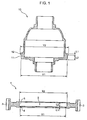
- Fig. 1 is an exploded cross-sectional view illustrating a configuration of parts that are objects to be bonded according to the present embodiment.
- a ring gear 1 and a differential case 10 that are parts of a vehicle are bonded using the bonding method according to the present invention.
- the differential case 10 is a case (differential gear case) for storing a pinion gear and a side gear of a differential mechanism, and corresponds to the second metallic member according to the present invention.
- the differential case 10 is made of cast iron and spheroidal graphitic cast iron such as FCD 450 and FCD 550 is preferable as a specific example thereof.
- the differential case 10 is made of a hollow body extending in an axial direction, and includes a multistage outer circumferential wall section having a plurality of large and small outer diameters. Specifically, a first outer diameter section 11 having an outer diameter of Y1 and a second outer diameter section 12 having an outer diameter of Y2 that is greater than the outer diameter Y1 are formed on the outer circumferential wall section of the differential case 10.
- the ring gear 1 is a gear part which receives a driving force transmitted from a transmission and which corresponds to the first metallic member according to the present invention.
- the ring gear 1 is made of steel and case hardening steel such as SCR 420H is preferable as a specific example thereof.
- the ring gear 1 is made of a ringed member having an opening 2 that penetrates in a thickness direction.
- a gear section 3 that meshes with an output gear of the transmission is formed on an outermost circumferential section of the ring gear 1.
- a first inner diameter section 4 having an inner diameter of X1 and a second inner diameter section 5 having an inner diameter of X2 that is greater than the inner diameter X1 are formed on an inner circumferential wall section of the ring gear 1 that surrounds the opening 2.
- the relationships between the inner diameters X1 and X2 of the ring gear 1 and the outer diameters Y1 and Y2 of the differential case 10 are such that the outer diameter Y1 of the first outer diameter section 11 is slightly greater than the inner diameter X1 of the first inner diameter section 4 and the outer diameter Y2 of the second outer diameter section 12 is slightly greater than the inner diameter X2 of the second inner diameter section 5.
- differences (tightening margins) between the radii of the respective outer diameter sections 11 and 12 and the radii of the respective inner diameter sections 4 and 5 are both set to S.
- the first inner diameter section 4 of the ring gear 1 and the second outer diameter section 12 of the differential case 10 both have axial lengths of L1
- the second inner diameter section 5 of the ring gear 1 and the first outer diameter section 11 of the differential case 10 both have axial lengths of L2, where L1 ⁇ L2.
- Fig. 2 is a diagram illustrating a basic configuration of a bonding apparatus 20 used when bonding the ring gear 1 and the differential case 10.
- the bonding apparatus 20 includes an upper electrode 21 and a lower electrode 22, a pressurizing mechanism (not shown) that pressurizes the respective electrodes 21 and 22 in an axial direction (an upward-downward direction in Fig. 2 ), and a power unit 23 that supplies a high current for bonding to the respective electrodes 21 and 22.
- Bonding using the bonding apparatus 20 as described above is performed by energizing the ring gear 1 and the differential case 10 with the upper electrode 21 and the lower electrode 22 while pressurizing the members 1 and 10 in the axial direction, in a state where the differential case 10 is inserted into the opening 2 of the ring gear 1 to be temporarily fixed.
- Fig. 2 illustrates a case where the upper electrode 21 and the lower electrode 22 are vertically arranged so as to oppose each other and the ring gear 1 and the differential case 10 are sandwiched between the upper electrode 21 and the lower electrode 22 to be bonded, for example, it is obvious that bonding can also be performed in a state where the electrodes 21 and 22 are horizontally arranged so as to oppose each other.
- the differential case 10 is inserted downward into the opening 2 of the ring gear 1.
- the ring gear 1 is placed on the lower electrode 22 in a posture where the first inner diameter section 4 is positioned lower than the second inner diameter section 5, and the differential case 10 is inserted downward from above the ring gear 1.
- the first outer diameter section 11 of the differential case 10 is set lower than the second outer diameter section 12 and the first outer diameter section 11 is inserted first into the ring gear 1.
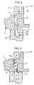
- Fig. 3 is an enlarged view of section A in Fig. 2 and illustrates a state where the aforementioned insertion operation of the differential case 10 has been completed.
- the respective outer diameters Y1, Y2 of the first outer diameter section 11 and the second outer diameter section 12 of the differential case 10 are greater than the respective inner diameters X1, X2 of the first inner diameter section 4 and the second inner diameter section 5 of the ring gear 1 by precisely the tightening margin S, as illustrated in Fig. 3 , when the differential case 10 is inserted into the ring gear 1, an outermost circumferential part of the first outer diameter section 11 abuts the first inner diameter section 4 and an outermost circumferential part of the second outer diameter section 12 abuts the second inner diameter section 5.
- the first inner diameter section 4 and the first outer diameter section 11 as well as the second inner diameter section 5 and the second outer diameter section 12 respectively abut each other at the same time.
- corners of the respective inner diameter sections 4, 5 and the respective outer diameter sections 11, 12 are chamfered and the chamfered parts are to abut each other. In this manner, the differential case 10 is temporarily fixed on the ring gear 1.
- the ring gear 1 and the differential case 10 are sandwiched from above and below and pressurized by the upper electrode 21 and the lower electrode 22, and a voltage for bonding is applied to both electrodes 21 and 22.
- the upper electrode 21 approaches the ring gear 1 and the differential case 10 which are temporarily fixed on the lower electrode 22 from above, a lower end of the upper electrode 21 abuts an upper surface of the second outer diameter section 12 of the differential case 10 and, in this state, a predetermined pressurizing force is applied to both electrodes 21 and 22 in an approaching direction (axial direction).
- a bonding voltage is applied to both electrodes 21 and 22.
- a large current instantaneously flows between the electrodes 21 and 22 via the ring gear 1 and the differential case 10.
- the ring gear 1 and the differential case 10 are in contact with each other via two points, namely, an abutting part of the first inner diameter section 4 and the first outer diameter section 11 and an abutting part of the second inner diameter section 5 and the second outer diameter section 12, the aforementioned current is to flow via the two abutting parts.
- the differential case 10 is pushed downward until the differential case 10 abuts the lower electrode 22, and in a state illustrated in Fig. 4 where the entire inner circumferential surface of the first inner diameter section 4 of the ring gear 1 comes into contact with the outer circumferential surface of the first outer diameter section 11 of the differential case 10 and the entire outer circumferential surface of the second outer diameter section 12 of the differential case 10 comes into contact with the inner circumferential surface of the second inner diameter section 5 of the ring gear 1, energization between the electrodes 21 and 22 is suspended to resolidify the metals on the respective contact surfaces, thereby forming two junctions P1 and P2 as illustrated in Fig. 4 .
- metal softening and plastic flow that occur at the respective contact surfaces between the first inner diameter section 4 and the first outer diameter section 11 and between the second inner diameter section 5 and the second outer diameter section 12 removes oxide film, foreign objects and the like, and by suspending energization in this state, newly-formed surfaces of the metals are metallurgically bonded to each other and resolidified. Accordingly, the first junction P1 is formed between the first inner diameter section 4 and the first outer diameter section 11 and the second junction P2 is formed between the second inner diameter section 5 and the second outer diameter section 12.
- reference characters Q1 and Q2 in Fig. 4 denote burrs formed by metal pushed out, by the amount of the tightening margin S, from between the first inner diameter section 4 and the first outer diameter section 11 and from between the second inner diameter section 5 and the second outer diameter section 12.
- first junction P1 and the second junction P2 formed in this case form a gap 15 therebetween in which the metals do not come contact with each other.
- first and second inner diameter sections 4 and 5 of the ring gear 1 and the first and second outer diameter sections 11 and 12 of the differential case 10 are in a dimensional relationship illustrated in Fig.
- the first inner diameter section 4 with an inner diameter of X1 and the second inner diameter section 5 with an inner diameter of X2 that is greater than the inner diameter of X1 are formed on the inner circumferential wall section of the ring gear 1, and the first outer diameter section 11 and the second outer diameter section 12 respectively having outer diameters Y1 and Y2 that are respectively greater than the inner diameters X1 and X2 by precisely the tightening margin S are formed on the outer circumferential wall section of the differential case 10.
- the joint strength can be increased by forming a single junction with a long junction length without dividing the junction into two parts (PI and P2) as is the case with the embodiment described above.
- PI and P2 two parts
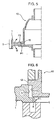
- a modulus of section of the junctions increases in comparison to a case where, for example, the respective junctions P1 and P2 are continuously arranged in the axial direction. Therefore, in particular, when a bending moment M such as illustrated in Fig. 5 is applied on the ring gear 1, a force acting on the junctions P1 and P2 is reduced and bending rigidity is further enhanced. Moreover, since the ring gear 1 receives forces from various directions due to a driving force transferred to the gear section 3 of the ring gear 1, the reliability of the differential mechanism can be further increased by improving bending rigidity as described above.
- the abutting timings of the two locations need not necessarily be precisely the same and a moderate difference in timings may exist.
- a difference arises between the timing where the first inner diameter section 4 abuts the first outer diameter section 11 and the timing where the second inner diameter section 5 abuts the second outer diameter section 12.
- the dimensional difference ⁇ L is small as illustrated in Fig. 6 , the difference in abutting timings is also small and bonding can conceivably be performed without incidence.
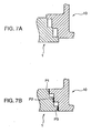
- Figs. 7A and 7B are diagrams describing a case where three junctions (P1, P2, and P3) have been arranged, wherein Fig. 7A illustrates a state before bonding and Fig. 7B illustrates a state after bonding.
- the bonding method according to the present invention is naturally applicable to other metal parts made of materials not limited to steel and cast iron. Since the bonding method according to the present invention involves bonding by metal softening and plastic flow, there are less constraints on materials compared to fusion bonding such as arc welding and laser welding and the bonding method can potentially be applied to various materials.
- the bonding method according to the present invention is a method of bonding metalic members, by which a first metallic member including an opening and a second metallic member including an outer circumferential wall section capable of coming into partial contact with an inner circumferential wall section of the first metallic member that surrounds the opening are bonded to each other by resistance heating through energization while applying pressure in an axial direction of the metallic members.
- the method includes: forming a first inner diameter section having a predetermined inner diameter and a second inner diameter section having an inner diameter that is greater than the inner diameter of the first inner diameter section on the inner circumferential wall section of the first metallic member; and then forming a first outer diameter section and a second outer diameter section having outer diameters that are greater than the inner diameters of the first inner diameter section and the second inner diameter section respectively by a predetermined amount on the outer circumferential wall section of the second metallic member.
- the first and second outer diameter sections of the second metallic member are abutted respectively against the first and second inner diameter sections of the first metallic member, and the first metallic member and the second metallic member are energized by a pair of electrodes while pressurizing both metallic members in an axial direction thereof.
- a first junction where the first inner diameter section and the first outer diameter section are bonded and a second junction where the second inner diameter section and the second outer diameter section are bonded are formed between both metallic members, and a gap is further formed in which the metals do not come into contact with each other between both junctions over a predetermined axial length.
- the first inner diameter section and the first outer diameter section, and the second inner diameter section and the second outer diameter section are simultaneously abutted to each other and energization by the electrodes is started in this state.
- the metallic bonded body according to the present invention is a metallic bonded body, in which a first metallic member including an opening and a second metallic member including an outer circumferential wall section capable of coming into partial contact with an inner circumferential wall section of the first metallic member that surrounds the opening are bonded to each other by resistance heating through energization while applying pressure in an axial direction of the metallic members.
- a first inner diameter section having a predetermined inner diameter and a second inner diameter section having an inner diameter that is greater than the inner diameter of the first inner diameter section are formed on the inner circumferential wall section of the first metallic member, a first outer diameter section and a second outer diameter section having outer diameters that are greater than the inner diameters of the first inner diameter section and the second inner diameter section respectively by a predetermined amount prior to bonding are formed on the outer circumferential wall section of the second metallic member.
- a first junction where the first inner diameter section and the first outer diameter section are bonded and a second junction where the second inner diameter section and the second outer diameter section are bonded are formed between the first metallic member and the second metallic member, and a gap in which the metals do not come into contact with each other is formed between both junctions over a predetermined axial length.
- first and second metallic members by bonding together the first and second metallic members via two junctions (first and second junctions) that are separated from each other in an axial direction, an advantage is achieved in that, in particular, rigidity to bending is effectively improved.
- a preferable application includes a ring gear as the first metallic member and a differential case as the second metallic member.
- an advantage is achieved in that the ring gear and the differential case (differential gear case) can be bonded by high strength and the reliability of a differential mechanism can be further enhanced.
Landscapes
- Engineering & Computer Science (AREA)
- Mechanical Engineering (AREA)
- Retarders (AREA)
- Gears, Cams (AREA)
- Pressure Welding/Diffusion-Bonding (AREA)
Description
- The present invention relates to a method of bonding, by resistance heating through energization while applying pressure in an axial direction, a first metallic member including an opening and a second metallic member including an outer circumferential wall section capable of coming into partial contact with an inner circumferential wall section of the first metallic member that surrounds the opening, and the like.
- Conventionally, a bonding method described in Japanese Patent Application Laid-open No.
2004-17048 2004-17048 - In this case, a junction of the first metallic member and the second metallic member takes the form of a diffusion bonding instead of a fusion bonding. In other words, by energization while applying a pressurizing force on both of the metallic members, the metals at contact portions are softened and a plastic flow is generated to metallurgically join newly-formed surfaces of the metals.
- A ring mash bonding method such as that described in Japanese Patent Application Laid-open No.
2004-17048 - However, with the method disclosed in Japanese Patent Application Laid-open No.
2004-17048 - The present invention has been made in view of the circumstances described above, and an object of the present invention is to provide a method of bonding metallic members and a metallic bonded body capable of obtaining a high joint strength with low bonding energy.
- In order to solve the problem described above, the present invention provides a method of bonding metal members, by which a first metallic member including an opening and a second metallic member including an outer circumferential wall section capable of coming into partial contact with an inner circumferential wall section of the first metallic member that surrounds the opening are bonded to each other by resistance heating through energization while applying pressure in an axial direction of the metallic members, the method comprising the steps of: forming a first inner diameter section having a predetermined inner diameter and a second inner diameter section having an inner diameter that is greater than the inner diameter of the first inner diameter section on the inner circumferential wall section of the first metallic member; forming a first outer diameter section and a second outer diameter section having outer diameters that are greater than the inner diameters of the first inner diameter section and the second inner diameter section respectively by a predetermined amount on the outer circumferential wall section of the second metallic member; and forming, by respectively abutting the first and second outer diameter sections of the second metallic member against the first and second inner diameter sections of the first metallic member and energizing the first metallic member and the second metallic member by a pair of electrodes while pressurizing both metallic members in an axial direction thereof, a first junction where the first inner diameter section and the first outer diameter section are bonded and a second junction where the second inner diameter section and the second outer diameter section are bonded between both metallic members, and further forming a gap in which the metals do not come into contact with each other between both junctions over a predetermined axial length.
- The present invention also provides a metallic bonded body according to
claim 3. -
-
Fig. 1 is an exploded cross-sectional view of a ring gear and a differential case that are objects to be bonded; -
Fig. 2 is a diagram illustrating a basic configuration of a bonding apparatus used when bonding the ring gear and the differential case; -
Fig. 3 is an enlarged view of section A illustrated inFig. 2 ; -
Fig. 4 is an equivalent diagram ofFig. 2 illustrating a state where bonding is completed; -
Fig. 5 is a diagram for describing a state where a bending moment is applied to the ring gear; -
Fig. 6 is a diagram for describing a modification of the present invention; and -
Figs. 7A and 7B are diagrams for describing another modification of the present invention, whereinFig. 7A illustrates a state before bonding andFig. 7B illustrates a state after bonding. - Hereinafter, a preferred embodiment of the present invention will be described with reference to the drawings.
Fig. 1 is an exploded cross-sectional view illustrating a configuration of parts that are objects to be bonded according to the present embodiment. As illustrated inFig. 1 , in the present embodiment, aring gear 1 and adifferential case 10 that are parts of a vehicle are bonded using the bonding method according to the present invention. - The
differential case 10 is a case (differential gear case) for storing a pinion gear and a side gear of a differential mechanism, and corresponds to the second metallic member according to the present invention. Thedifferential case 10 is made of cast iron and spheroidal graphitic cast iron such as FCD 450 and FCD 550 is preferable as a specific example thereof. - The
differential case 10 is made of a hollow body extending in an axial direction, and includes a multistage outer circumferential wall section having a plurality of large and small outer diameters. Specifically, a firstouter diameter section 11 having an outer diameter of Y1 and a secondouter diameter section 12 having an outer diameter of Y2 that is greater than the outer diameter Y1 are formed on the outer circumferential wall section of thedifferential case 10. - The
ring gear 1 is a gear part which receives a driving force transmitted from a transmission and which corresponds to the first metallic member according to the present invention. Thering gear 1 is made of steel and case hardening steel such as SCR 420H is preferable as a specific example thereof. - The
ring gear 1 is made of a ringed member having anopening 2 that penetrates in a thickness direction. Agear section 3 that meshes with an output gear of the transmission is formed on an outermost circumferential section of thering gear 1. In addition, a firstinner diameter section 4 having an inner diameter of X1 and a secondinner diameter section 5 having an inner diameter of X2 that is greater than the inner diameter X1 are formed on an inner circumferential wall section of thering gear 1 that surrounds theopening 2. - The relationships between the inner diameters X1 and X2 of the
ring gear 1 and the outer diameters Y1 and Y2 of thedifferential case 10 are such that the outer diameter Y1 of the firstouter diameter section 11 is slightly greater than the inner diameter X1 of the firstinner diameter section 4 and the outer diameter Y2 of the secondouter diameter section 12 is slightly greater than the inner diameter X2 of the secondinner diameter section 5. As illustrated inFig. 3 to be described later, differences (tightening margins) between the radii of the respectiveouter diameter sections inner diameter sections - In addition, with regard to the axial lengths of the respective
outer diameter sections inner diameter sections Fig. 1 , the firstinner diameter section 4 of thering gear 1 and the secondouter diameter section 12 of thedifferential case 10 both have axial lengths of L1, and the secondinner diameter section 5 of thering gear 1 and the firstouter diameter section 11 of thedifferential case 10 both have axial lengths of L2, where L1 < L2. -
Fig. 2 is a diagram illustrating a basic configuration of abonding apparatus 20 used when bonding thering gear 1 and thedifferential case 10. As illustrated inFig. 2 , thebonding apparatus 20 includes anupper electrode 21 and alower electrode 22, a pressurizing mechanism (not shown) that pressurizes therespective electrodes Fig. 2 ), and apower unit 23 that supplies a high current for bonding to therespective electrodes bonding apparatus 20 as described above is performed by energizing thering gear 1 and thedifferential case 10 with theupper electrode 21 and thelower electrode 22 while pressurizing themembers differential case 10 is inserted into theopening 2 of thering gear 1 to be temporarily fixed. WhileFig. 2 illustrates a case where theupper electrode 21 and thelower electrode 22 are vertically arranged so as to oppose each other and thering gear 1 and thedifferential case 10 are sandwiched between theupper electrode 21 and thelower electrode 22 to be bonded, for example, it is obvious that bonding can also be performed in a state where theelectrodes - A procedure of bonding the
ring gear 1 and thedifferential case 10 will now be described in more detail. In order to join thering gear 1 and thedifferential case 10, first, thedifferential case 10 is inserted downward into theopening 2 of thering gear 1. Specifically, thering gear 1 is placed on thelower electrode 22 in a posture where the firstinner diameter section 4 is positioned lower than the secondinner diameter section 5, and thedifferential case 10 is inserted downward from above thering gear 1. In doing so, the firstouter diameter section 11 of thedifferential case 10 is set lower than the secondouter diameter section 12 and the firstouter diameter section 11 is inserted first into thering gear 1. -
Fig. 3 is an enlarged view of section A inFig. 2 and illustrates a state where the aforementioned insertion operation of thedifferential case 10 has been completed. As described above, since the respective outer diameters Y1, Y2 of the firstouter diameter section 11 and the secondouter diameter section 12 of thedifferential case 10 are greater than the respective inner diameters X1, X2 of the firstinner diameter section 4 and the secondinner diameter section 5 of thering gear 1 by precisely the tightening margin S, as illustrated inFig. 3 , when thedifferential case 10 is inserted into thering gear 1, an outermost circumferential part of the firstouter diameter section 11 abuts the firstinner diameter section 4 and an outermost circumferential part of the secondouter diameter section 12 abuts the secondinner diameter section 5. In this case, since the axial length of the secondinner diameter section 5 of thering gear 1 is equal to the axial length of the firstouter diameter section 11 of the differential case 10 (both have a dimension of L2 illustrated inFig. 1 ), the firstinner diameter section 4 and the firstouter diameter section 11 as well as the secondinner diameter section 5 and the secondouter diameter section 12 respectively abut each other at the same time. Moreover, in the illustrated example, corners of the respectiveinner diameter sections outer diameter sections differential case 10 is temporarily fixed on thering gear 1. - Once the temporary fixing is completed as described above, next, the
ring gear 1 and thedifferential case 10 are sandwiched from above and below and pressurized by theupper electrode 21 and thelower electrode 22, and a voltage for bonding is applied to bothelectrodes upper electrode 21 approaches thering gear 1 and thedifferential case 10 which are temporarily fixed on thelower electrode 22 from above, a lower end of theupper electrode 21 abuts an upper surface of the secondouter diameter section 12 of thedifferential case 10 and, in this state, a predetermined pressurizing force is applied to bothelectrodes power unit 23, a bonding voltage is applied to bothelectrodes - In response to the application of a voltage as described above, a large current instantaneously flows between the
electrodes ring gear 1 and thedifferential case 10. In this case, since thering gear 1 and thedifferential case 10 are in contact with each other via two points, namely, an abutting part of the firstinner diameter section 4 and the firstouter diameter section 11 and an abutting part of the secondinner diameter section 5 and the secondouter diameter section 12, the aforementioned current is to flow via the two abutting parts. - Consequently, resistance heating due to energization occurs, causing metal softening and plastic flow at both of the abutting parts. In this case, since the pressurization by the
electrodes differential case 10 is gradually pushed downward with respect to thering gear 1 in accordance with metal softens. Accordingly, areas of contact of thedifferential case 10 and the ring gear 1 (in other words, the respective areas of contact between the firstinner diameter section 4 and the firstouter diameter section 11 and between the secondinner diameter section 5 and the second outer diameter section 12) increase, in turn causing an increase in regions where metal softens. - Subsequently, the
differential case 10 is pushed downward until thedifferential case 10 abuts thelower electrode 22, and in a state illustrated inFig. 4 where the entire inner circumferential surface of the firstinner diameter section 4 of thering gear 1 comes into contact with the outer circumferential surface of the firstouter diameter section 11 of thedifferential case 10 and the entire outer circumferential surface of the secondouter diameter section 12 of thedifferential case 10 comes into contact with the inner circumferential surface of the secondinner diameter section 5 of thering gear 1, energization between theelectrodes Fig. 4 . - In other words, metal softening and plastic flow that occur at the respective contact surfaces between the first
inner diameter section 4 and the firstouter diameter section 11 and between the secondinner diameter section 5 and the secondouter diameter section 12 removes oxide film, foreign objects and the like, and by suspending energization in this state, newly-formed surfaces of the metals are metallurgically bonded to each other and resolidified. Accordingly, the first junction P1 is formed between the firstinner diameter section 4 and the firstouter diameter section 11 and the second junction P2 is formed between the secondinner diameter section 5 and the secondouter diameter section 12. Moreover, reference characters Q1 and Q2 inFig. 4 denote burrs formed by metal pushed out, by the amount of the tightening margin S, from between the firstinner diameter section 4 and the firstouter diameter section 11 and from between the secondinner diameter section 5 and the secondouter diameter section 12. - Bonding of the
ring gear 1 and thedifferential case 10 is completed using the processes described above. The first junction P1 and the second junction P2 formed in this case form agap 15 therebetween in which the metals do not come contact with each other. Specifically, since the first and secondinner diameter sections ring gear 1 and the first and secondouter diameter sections differential case 10 are in a dimensional relationship illustrated inFig. 1 and the like (in other words, Y1 = (X1 + 2S) < Y2 = (X2 + 2S), L1 < L2), in the state after bonding, the first junction P1 and the second junction P2 are formed respectively offset in a radial direction and in an axial direction and, as a result, thegap 15 is formed over a predetermined axial length between both junctions P1 and P2. - As described above, in the present embodiment, when bonding the
ring gear 1 to thedifferential case 10, first, the firstinner diameter section 4 with an inner diameter of X1 and the secondinner diameter section 5 with an inner diameter of X2 that is greater than the inner diameter of X1 are formed on the inner circumferential wall section of thering gear 1, and the firstouter diameter section 11 and the secondouter diameter section 12 respectively having outer diameters Y1 and Y2 that are respectively greater than the inner diameters X1 and X2 by precisely the tightening margin S are formed on the outer circumferential wall section of thedifferential case 10. Subsequently, by respectively abutting the first and secondouter diameter sections differential case 10 to the first and secondinner diameter sections ring gear 1 and by pressurizing thering gear 1 and thedifferential case 10 in an axial direction and energizing thering gear 1 and thedifferential case 10 using the pair ofelectrodes inner diameter section 4 and the firstouter diameter section 11 are bonded and the second junction P2 where the secondinner diameter section 5 and the secondouter diameter section 12 are bonded are formed between themembers gap 15 in which the metals do not come contact with each other is formed over a predetermined axial length between both junctions P1 and P2. Such a configuration is advantageous in that a high joint strength can be obtained while only requiring low bonding energy. - In other words, in the embodiment described above, since the inner circumferential wall section of the
ring gear 1 and the outer circumferential wall section of thedifferential case 10 are bonded via two junctions (first and second junctions) P1 and P2, the two junctions P1 and P2 are separated from each other in an axial direction, and thegap 15 is formed between the junctions P1 and P2, advantages can be achieved in that a superior junction structure which is particularly resistant to bending can be constructed without immoderately increasing the axial lengths (junction lengths) of the respective junctions P1 and P2 and joint strength can be effectively enhanced while avoiding an increase in the energy required by bonding. - For example, if a sole purpose is to increase joint strength, the joint strength can be increased by forming a single junction with a long junction length without dividing the junction into two parts (PI and P2) as is the case with the embodiment described above. However, in such a case, a current value or a pressurizing force necessary during bonding increases, resulting in a larger facility and increased cost.
- In contrast thereto, when forming two junctions P1 and P2 that are separated from each other in an axial direction as is the case with the embodiment described above, a modulus of section of the junctions increases in comparison to a case where, for example, the respective junctions P1 and P2 are continuously arranged in the axial direction. Therefore, in particular, when a bending moment M such as illustrated in
Fig. 5 is applied on thering gear 1, a force acting on the junctions P1 and P2 is reduced and bending rigidity is further enhanced. Moreover, since thering gear 1 receives forces from various directions due to a driving force transferred to thegear section 3 of thering gear 1, the reliability of the differential mechanism can be further increased by improving bending rigidity as described above. - Furthermore, since the existence of the
gap 15 between the respective junctions P1 and P2 enables the burr Q2 caused by bonding to escape into thegap 15, for example, a junction of thering gear 1 to thedifferential case 10 via the burr Q2 does not occur and an advantage can be achieved in that a poor junction attributable to the burr Q2 is effectively prevented. - In addition, since the above embodiment is arranged so that, at the start of bonding of the
ring gear 1 and thedifferential case 10, the firstinner diameter section 4 and the firstouter diameter section 11, and the secondinner diameter section 5 and the secondouter diameter section 12, are simultaneously abutted to each other as illustrated inFigs. 2 and3 and that energization is started in this state, no variations occur in the quality of the two junctions P1 and P2 and an advantage can be achieved in that a highly reliable and uniform junction structure can be constructed. - For example, in a case where the abutting of the first
inner diameter section 4 and the firstouter diameter section 11 and the abutting of the secondinner diameter section 5 and the secondouter diameter section 12 occur at significantly different timings, an excessive current flows through whichever has been abutted first, creating a risk of a significant decrease in joint strength due to the occurrence of a phenomenon called expulsion (dispersion) in which a metallic member disperses. In contrast, in the above embodiment, an advantage is achieved in that, by setting the abutting timings of the two locations to be the same, a situation such as described above can be avoided and joint strength can be maintained at a high level. - Obviously, it is conceivable that a moderate difference in timings only results in a short overcurrent period and therefore hardly affects quality. Therefore, the abutting timings of the two locations need not necessarily be precisely the same and a moderate difference in timings may exist. For example, as illustrated in
Fig. 6 , in a case where a design constraint or the like does not allow the axial length of the secondinner diameter section 5 of thering gear 1 to be the same as the axial length of the firstouter diameter section 11 of the differential case 10 (a case where an illustrated dimensional difference ΔL exists), a difference arises between the timing where the firstinner diameter section 4 abuts the firstouter diameter section 11 and the timing where the secondinner diameter section 5 abuts the secondouter diameter section 12. However, even in this case, if the dimensional difference ΔL is small as illustrated inFig. 6 , the difference in abutting timings is also small and bonding can conceivably be performed without incidence. - Moreover, while the
ring gear 1 and thedifferential case 10 have been bonded via the two junctions P1 and P2 that are separated from each other in the axial direction in the embodiment described above, the number of junctions need not be limited to two and thering gear 1 and thedifferential case 10 may alternatively be bonded via three or more junctions.Figs. 7A and 7B are diagrams describing a case where three junctions (P1, P2, and P3) have been arranged, whereinFig. 7A illustrates a state before bonding andFig. 7B illustrates a state after bonding. - Furthermore, while a case where a
steel ring gear 1 and a cast-iron differential case 10 are bonded has been described as an example in the above embodiment, the bonding method according to the present invention is naturally applicable to other metal parts made of materials not limited to steel and cast iron. Since the bonding method according to the present invention involves bonding by metal softening and plastic flow, there are less constraints on materials compared to fusion bonding such as arc welding and laser welding and the bonding method can potentially be applied to various materials. - Finally, a summarized description of configurations and advantages of the present invention disclosed based on the embodiment described above will be given.
- The bonding method according to the present invention is a method of bonding metalic members, by which a first metallic member including an opening and a second metallic member including an outer circumferential wall section capable of coming into partial contact with an inner circumferential wall section of the first metallic member that surrounds the opening are bonded to each other by resistance heating through energization while applying pressure in an axial direction of the metallic members. More specifically, the method includes: forming a first inner diameter section having a predetermined inner diameter and a second inner diameter section having an inner diameter that is greater than the inner diameter of the first inner diameter section on the inner circumferential wall section of the first metallic member; and then forming a first outer diameter section and a second outer diameter section having outer diameters that are greater than the inner diameters of the first inner diameter section and the second inner diameter section respectively by a predetermined amount on the outer circumferential wall section of the second metallic member. The first and second outer diameter sections of the second metallic member are abutted respectively against the first and second inner diameter sections of the first metallic member, and the first metallic member and the second metallic member are energized by a pair of electrodes while pressurizing both metallic members in an axial direction thereof. Whereby, a first junction where the first inner diameter section and the first outer diameter section are bonded and a second junction where the second inner diameter section and the second outer diameter section are bonded are formed between both metallic members, and a gap is further formed in which the metals do not come into contact with each other between both junctions over a predetermined axial length.
- With the bonding method according to the present embodiment, since the inner circumferential wall section of the first metallic member and the outer circumferential wall section of the second metallic member are bonded via two junctions (first and second junctions), the two junctions are separated from each other in an axial direction, and the gap is formed between the junctions, advantages can be achieved in that a superior junction structure which is particularly resistant to bending can be constructed without immoderately increasing the axial lengths (junction lengths) of the respective junctions, and a joint strength can be effectively enhanced while avoiding an increase in the energy required by bonding.
- In the bonding method according to the present invention, favorably, at the start of bonding of the first metallic member and the second metallic member, the first inner diameter section and the first outer diameter section, and the second inner diameter section and the second outer diameter section, are simultaneously abutted to each other and energization by the electrodes is started in this state.
- Consequently, no variations occur in the quality of the two junctions and a highly reliable and uniform junction structure can advantageously be constructed.
- In addition, the metallic bonded body according to the present invention is a metallic bonded body, in which a first metallic member including an opening and a second metallic member including an outer circumferential wall section capable of coming into partial contact with an inner circumferential wall section of the first metallic member that surrounds the opening are bonded to each other by resistance heating through energization while applying pressure in an axial direction of the metallic members. More specifically, a first inner diameter section having a predetermined inner diameter and a second inner diameter section having an inner diameter that is greater than the inner diameter of the first inner diameter section are formed on the inner circumferential wall section of the first metallic member, a first outer diameter section and a second outer diameter section having outer diameters that are greater than the inner diameters of the first inner diameter section and the second inner diameter section respectively by a predetermined amount prior to bonding are formed on the outer circumferential wall section of the second metallic member. A first junction where the first inner diameter section and the first outer diameter section are bonded and a second junction where the second inner diameter section and the second outer diameter section are bonded are formed between the first metallic member and the second metallic member, and a gap in which the metals do not come into contact with each other is formed between both junctions over a predetermined axial length.
- With the metallic bonded body according to the present invention, by bonding together the first and second metallic members via two junctions (first and second junctions) that are separated from each other in an axial direction, an advantage is achieved in that, in particular, rigidity to bending is effectively improved.
- While various specific examples of the application of the metallic bonded body according to the present invention is conceivable, for example, a preferable application includes a ring gear as the first metallic member and a differential case as the second metallic member.
- According to the configuration described above, an advantage is achieved in that the ring gear and the differential case (differential gear case) can be bonded by high strength and the reliability of a differential mechanism can be further enhanced.
- This application is based on Japanese Patent application No.
2009-253185
Claims (4)
- A method of bonding metal members, by which a first metallic member (1) including an opening (2) and a second metallic member (10) including an outer circumferential wall section capable of coming into partial contact with an inner circumferential wall section of the first metallic member (1) that surrounds the opening (2) are bonded to each other by resistance heating through energization while applying pressure in an axial direction of the metallic members,
the method comprising the steps of:forming a first inner diameter section (4) having a predetermined inner diameter (X1) and a second inner diameter section (5) having an inner diameter (X2) that is greater than the inner diameter (X1) of the first inner diameter section (4) on the inner circumferential wall section of the first metallic member (1);forming a first outer diameter section (11) and a second outer diameter section (12) having outer diameters (Y1, Y2) that are greater than the inner diameters (X1, X2) of the first inner diameter section (4) and the second inner diameter section (5) respectively by a predetermined amount on the outer circumferential wall section of the second metallic member (10); and characterized by the steps of:forming, by respectively abutting the first and second outer diameter sections (11, 12) of the second metallic member (10) against the first and second inner diameter sections (4, 5) of the first metallic member (1) and energizing the first metallic member (1) and the second metallic member (10) by a pair of electrodes (21, 22) while pressurizing both metallic members (1, 10) in an axial direction thereof, a first junction (P1) where the first inner diameter section (4) and the first outer diameter section (11) are bonded and a second junction (P2) where the second inner diameter section (5) and the second outer diameter section (12) are bonded between both metallic members (1, 10), and further forming a gap (15) in which the metals do not come into contact with each other between both junctions (P1, P2) over a predetermined axial length. - The method of bonding metallic members according to claim 1, wherein,
at the start of bonding of the first metallic member (1) and the second metallic member (10), the first inner diameter section (4) and the first outer diameter section (11), and the second inner diameter section (5) and the second outer diameter section (12), are simultaneously abutted to each other and energization by the electrodes (21, 22) is started in this state. - A metallic bonded body, in which a first metallic member (1) including an opening (2) and a second metallic member (10) including an outer circumferential wall section capable of coming into partial contact with an inner circumferential wall section of the first metallic member (1) that surrounds the opening (2) are bonded to each other by resistance heating through energization while applying pressure in an axial direction of the metallic members, wherein,
a first inner diameter section (4) having a predetermined inner diameter (X1) and a second inner diameter section (5) having an inner diameter (X2) that is greater than the inner diameter (X1) of the first inner diameter section (4) are formed on the inner circumferential wall section of the first metallic member (1),
a first outer diameter section (11) and a second outer diameter section (12) having outer diameters (Y1, Y2) that are greater than the inner diameters (X1, X2) of the first inner diameter section (4) and the second inner diameter section (5) respectively by a predetermined amount prior to bonding are formed on the outer circumferential wall section of the second metallic member (10), and characterized by
a first junction (P1) where the first inner diameter section (4) and the first outer diameter section (11) are bonded and a second junction (P2) where the second inner diameter section (5) and the second outer diameter section (12) are bonded are formed between the first metallic member (1) and the second metallic member (10), and a gap (15) in which the metals do not come into contact with each other is formed between both junctions (P1, P2) over a predetermined axial length. - The metallic bonded body according to claim 3, wherein the first metallic member (1) is a ring gear and the second metallic member (10) is a differential case.
Applications Claiming Priority (1)
| Application Number | Priority Date | Filing Date | Title |
|---|---|---|---|
| JP2009253185A JP5399206B2 (en) | 2009-11-04 | 2009-11-04 | Metal member joining method and metal joined body |
Publications (2)
| Publication Number | Publication Date |
|---|---|
| EP2319652A1 EP2319652A1 (en) | 2011-05-11 |
| EP2319652B1 true EP2319652B1 (en) | 2014-07-16 |
Family
ID=43513870
Family Applications (1)
| Application Number | Title | Priority Date | Filing Date |
|---|---|---|---|
| EP10014202.5A Active EP2319652B1 (en) | 2009-11-04 | 2010-11-02 | Method of bonding metallic members, and metallic bonded body |
Country Status (4)
| Country | Link |
|---|---|
| US (1) | US8710393B2 (en) |
| EP (1) | EP2319652B1 (en) |
| JP (1) | JP5399206B2 (en) |
| CN (1) | CN102059437B (en) |
Families Citing this family (31)
| Publication number | Priority date | Publication date | Assignee | Title |
|---|---|---|---|---|
| JP5327130B2 (en) * | 2010-04-23 | 2013-10-30 | トヨタ自動車株式会社 | Ring gear welding method and welded structure |
| DE102011102064A1 (en) * | 2011-05-19 | 2012-11-22 | Trw Airbag Systems Gmbh | Method for producing a gas generator |
| US11152657B2 (en) | 2012-04-11 | 2021-10-19 | Ionic Materials, Inc. | Alkaline metal-air battery cathode |
| US11319411B2 (en) | 2012-04-11 | 2022-05-03 | Ionic Materials, Inc. | Solid ionically conducting polymer material |
| US11251455B2 (en) | 2012-04-11 | 2022-02-15 | Ionic Materials, Inc. | Solid ionically conducting polymer material |
| US9819053B1 (en) | 2012-04-11 | 2017-11-14 | Ionic Materials, Inc. | Solid electrolyte high energy battery |
| US12074274B2 (en) | 2012-04-11 | 2024-08-27 | Ionic Materials, Inc. | Solid state bipolar battery |
| US10559827B2 (en) | 2013-12-03 | 2020-02-11 | Ionic Materials, Inc. | Electrochemical cell having solid ionically conducting polymer material |
| KR102353151B1 (en) | 2013-12-03 | 2022-01-18 | 아이오닉 머터리얼스, 인코퍼레이션 | Solid, ionically conducting polymer material, and applications |
| JP7109879B2 (en) | 2014-04-01 | 2022-08-01 | イオニツク・マテリアルズ・インコーポレーテツド | High capacity polymer cathode and high energy density rechargeable battery containing said cathode |
| DE102015207176A1 (en) * | 2014-06-23 | 2015-12-24 | Zf Friedrichshafen Ag | Method for producing a chassis component |
| JP5990343B2 (en) * | 2014-08-18 | 2016-09-14 | オリジン電気株式会社 | Metal bonded body and metal bonded body manufacturing method |
| KR101814354B1 (en) * | 2014-10-10 | 2018-01-30 | 오리진 일렉트릭 캄파니 리미티드 | Electrical bonding method and electrical bonding device |
| DE102015205628A1 (en) * | 2015-03-27 | 2016-09-29 | Zf Friedrichshafen Ag | A method of manufacturing a landing gear assembly and chassis assembly made by such a method |
| CN108352565A (en) | 2015-06-04 | 2018-07-31 | 离子材料公司 | Lithium metal battery with solid polymer electrolyte |
| CN108140805B (en) | 2015-06-04 | 2022-03-01 | 离子材料公司 | Solid state bipolar battery |
| US11342559B2 (en) | 2015-06-08 | 2022-05-24 | Ionic Materials, Inc. | Battery with polyvalent metal anode |
| SG10201911155XA (en) | 2015-06-08 | 2020-01-30 | Ionic Materials Inc | Battery having aluminum anode and solid polymer electrolyte |
| JP2017064773A (en) * | 2015-10-01 | 2017-04-06 | 株式会社清水製作所 | Welding method of two member and joint member welded by the same |
| JP6607124B2 (en) * | 2016-03-31 | 2019-11-20 | アイシン・エィ・ダブリュ株式会社 | Differential joint structure |
| DE102016213451A1 (en) * | 2016-05-19 | 2017-11-23 | Robert Bosch Gmbh | High-pressure fuel pump |
| JP6109395B1 (en) * | 2016-10-18 | 2017-04-05 | 株式会社エフ・シー・シー | Manufacturing method of joint parts |
| EP3574542A4 (en) | 2017-01-26 | 2020-09-02 | Ionic Materials, Inc. | ALKALINE BATTERY CATHODE WITH SOLID POLYMER ELECTROLYTE |
| US10744556B2 (en) | 2017-12-21 | 2020-08-18 | American Axle & Manufacturing, Inc. | Method for forming a toothed article |
| JP6643759B2 (en) * | 2018-03-23 | 2020-02-12 | 株式会社オリジン | Fitting member, annular member, joined member, and method of manufacturing joined member |
| DE102018220105B4 (en) * | 2018-11-22 | 2021-01-21 | Audi Ag | Differential gear for a motor vehicle with an output gear pressed onto the housing through two press fits |
| JP7405523B2 (en) * | 2019-06-28 | 2023-12-26 | 武蔵精密工業株式会社 | transmission device |
| JP2021016862A (en) * | 2019-07-17 | 2021-02-15 | マツダ株式会社 | Metallic member joining method and joint structure |
| CN112647245B (en) * | 2019-10-10 | 2025-01-10 | 青岛海尔洗衣机有限公司 | Micro bubble nozzle and washing equipment having the same |
| JP6868733B1 (en) * | 2020-06-02 | 2021-05-12 | 株式会社オリジン | Manufacturing method and manufacturing equipment for joined articles |
| JP6882581B1 (en) * | 2020-06-02 | 2021-06-02 | 株式会社オリジン | Manufacturing method and manufacturing equipment for joined articles |
Family Cites Families (9)
| Publication number | Priority date | Publication date | Assignee | Title |
|---|---|---|---|---|
| JP2536200B2 (en) * | 1989-12-11 | 1996-09-18 | 三菱マテリアル株式会社 | Method for joining metal sintered materials, metal sintered material-made pool and method for manufacturing |
| JPH06218560A (en) * | 1993-01-21 | 1994-08-09 | Toyota Motor Corp | Manufacture of cylinder block |
| JP2004017048A (en) | 2002-06-12 | 2004-01-22 | Origin Electric Co Ltd | Ring mash welding method and apparatus |
| US6717091B2 (en) * | 2002-08-22 | 2004-04-06 | Delphi Technologies, Inc. | Method for metallurgically attaching together two tubes |
| US20040056001A1 (en) * | 2002-09-24 | 2004-03-25 | Delphi Technologies Inc. | Deformation resistance welding of sheet metal, tubes, and similar shapes |
| JP4397631B2 (en) * | 2003-06-27 | 2010-01-13 | 株式会社オーハシテクニカ | Press-fit joint structure and joint parts |
| JP2005081351A (en) * | 2003-09-04 | 2005-03-31 | Aisin Aw Co Ltd | Friction pressure welding member and differential gear equipped with member |
| US8202628B2 (en) | 2006-12-08 | 2012-06-19 | Musashi Seimitsu Kogyo Kabushiki Kaisha | Fusion-bonded product having high-strength part and manufacturing method thereof |
| JP4343989B1 (en) | 2008-04-10 | 2009-10-14 | 株式会社新川 | BONDING APPARATUS AND BONDING AREA POSITION RECOGNITION METHOD AND PROGRAM USED FOR BONDING APPARATUS |
-
2009
- 2009-11-04 JP JP2009253185A patent/JP5399206B2/en active Active
-
2010
- 2010-10-28 US US12/914,473 patent/US8710393B2/en active Active
- 2010-11-02 EP EP10014202.5A patent/EP2319652B1/en active Active
- 2010-11-04 CN CN201010544017.5A patent/CN102059437B/en active Active
Also Published As
| Publication number | Publication date |
|---|---|
| JP2011098358A (en) | 2011-05-19 |
| US8710393B2 (en) | 2014-04-29 |
| CN102059437A (en) | 2011-05-18 |
| US20110104511A1 (en) | 2011-05-05 |
| JP5399206B2 (en) | 2014-01-29 |
| CN102059437B (en) | 2015-09-02 |
| EP2319652A1 (en) | 2011-05-11 |
Similar Documents
| Publication | Publication Date | Title |
|---|---|---|
| US8710393B2 (en) | Method of bonding metallic members, and metallic bonded body | |
| JP5512395B2 (en) | Method for joining metal members | |
| CN103038017B (en) | The method be connected with wheel hub axle by welding current and press-in and axle and wheel hub are by this device connected and composed | |
| CN102131611B (en) | Liquid phase diffusion bonded pipe joint and manufacturing method thereof | |
| JP2012507645A (en) | Reinforcement | |
| US11161196B2 (en) | Metallic member bonding device for pressing rod-shaped or cylindrical first metallic member into hole portion of annular second metallic member to bond the same and bonding method therefor | |
| WO2016027650A1 (en) | Metal joined body and method for manufacturing metal joined body | |
| JP2008221321A (en) | Friction spot welding method | |
| CN109996635A (en) | The component groups zoarium of component, at least two components with engagement auxiliary element and the method for manufacture | |
| JP2011056531A (en) | Method for manufacturing piston rod | |
| JP6328367B2 (en) | Propeller shaft manufacturing method and propeller shaft | |
| CN114080292A (en) | Joining method and joining structure of metal parts | |
| JP2009000712A (en) | Joining method and joining structure of metal member | |
| JP4453506B2 (en) | Friction spot welding method | |
| JP6868733B1 (en) | Manufacturing method and manufacturing equipment for joined articles | |
| CN103398057B (en) | Steel pipe butt joint structure and crane with same | |
| JP2013226562A (en) | Welded joint | |
| JP7265282B2 (en) | Friction welding device and friction welding method | |
| EP3768462A1 (en) | Lap welding with designed gap for increased joint strength | |
| WO2021131988A1 (en) | Spot welding method | |
| JPH11309586A (en) | Metal tube joining method and metal cylindrical joint used in the method | |
| JP2026035063A (en) | Manufacturing method of bonded products | |
| JP2021102229A (en) | Spot welding method | |
| JP2010174563A (en) | Reinforcing bar having anchoring fixture, and method of manufacturing of reinforcing bar | |
| JP2011224604A (en) | Method of manufacturing highly-rigid and lightweight propeller shaft |
Legal Events
| Date | Code | Title | Description |
|---|---|---|---|
| PUAI | Public reference made under article 153(3) epc to a published international application that has entered the european phase |
Free format text: ORIGINAL CODE: 0009012 |
|
| AK | Designated contracting states |
Kind code of ref document: A1 Designated state(s): AL AT BE BG CH CY CZ DE DK EE ES FI FR GB GR HR HU IE IS IT LI LT LU LV MC MK MT NL NO PL PT RO RS SE SI SK SM TR |
|
| AX | Request for extension of the european patent |
Extension state: BA ME |
|
| RIN1 | Information on inventor provided before grant (corrected) |
Inventor name: HAMANO, MASATOSHI Inventor name: SAWAZAKI, TOMOO Inventor name: YAMAGATA, AKINOBU Inventor name: OKUMURA, SHINYA Inventor name: HASHIMOTO, AKIRA Inventor name: SASAKI, HIROJI Inventor name: HAYASHI, HIROAKI Inventor name: SHIINO, KAZUYUKI Inventor name: ISHIDA, KAZUYUKI Inventor name: FUJII, TAKESHI |
|
| 17P | Request for examination filed |
Effective date: 20110728 |
|
| GRAP | Despatch of communication of intention to grant a patent |
Free format text: ORIGINAL CODE: EPIDOSNIGR1 |
|
| RIC1 | Information provided on ipc code assigned before grant |
Ipc: B23K 11/093 20060101AFI20140123BHEP Ipc: B23K 33/00 20060101ALI20140123BHEP |
|
| INTG | Intention to grant announced |
Effective date: 20140207 |
|
| GRAS | Grant fee paid |
Free format text: ORIGINAL CODE: EPIDOSNIGR3 |
|
| GRAA | (expected) grant |
Free format text: ORIGINAL CODE: 0009210 |
|
| AK | Designated contracting states |
Kind code of ref document: B1 Designated state(s): AL AT BE BG CH CY CZ DE DK EE ES FI FR GB GR HR HU IE IS IT LI LT LU LV MC MK MT NL NO PL PT RO RS SE SI SK SM TR |
|
| REG | Reference to a national code |
Ref country code: GB Ref legal event code: FG4D |
|
| REG | Reference to a national code |
Ref country code: CH Ref legal event code: EP |
|
| REG | Reference to a national code |
Ref country code: IE Ref legal event code: FG4D |
|
| REG | Reference to a national code |
Ref country code: AT Ref legal event code: REF Ref document number: 677287 Country of ref document: AT Kind code of ref document: T Effective date: 20140815 |
|
| REG | Reference to a national code |
Ref country code: DE Ref legal event code: R096 Ref document number: 602010017421 Country of ref document: DE Effective date: 20140828 |
|
| REG | Reference to a national code |
Ref country code: FR Ref legal event code: TP Owner name: ORIGIN ELECTRIC COMPANY, LTD., JP Effective date: 20140916 |
|
| REG | Reference to a national code |
Ref country code: NL Ref legal event code: VDEP Effective date: 20140716 |
|
| REG | Reference to a national code |
Ref country code: AT Ref legal event code: MK05 Ref document number: 677287 Country of ref document: AT Kind code of ref document: T Effective date: 20140716 |
|
| REG | Reference to a national code |
Ref country code: LT Ref legal event code: MG4D |
|
| PG25 | Lapsed in a contracting state [announced via postgrant information from national office to epo] |
Ref country code: NO Free format text: LAPSE BECAUSE OF FAILURE TO SUBMIT A TRANSLATION OF THE DESCRIPTION OR TO PAY THE FEE WITHIN THE PRESCRIBED TIME-LIMIT Effective date: 20141016 Ref country code: GR Free format text: LAPSE BECAUSE OF FAILURE TO SUBMIT A TRANSLATION OF THE DESCRIPTION OR TO PAY THE FEE WITHIN THE PRESCRIBED TIME-LIMIT Effective date: 20141017 Ref country code: BG Free format text: LAPSE BECAUSE OF FAILURE TO SUBMIT A TRANSLATION OF THE DESCRIPTION OR TO PAY THE FEE WITHIN THE PRESCRIBED TIME-LIMIT Effective date: 20141016 Ref country code: LT Free format text: LAPSE BECAUSE OF FAILURE TO SUBMIT A TRANSLATION OF THE DESCRIPTION OR TO PAY THE FEE WITHIN THE PRESCRIBED TIME-LIMIT Effective date: 20140716 Ref country code: ES Free format text: LAPSE BECAUSE OF FAILURE TO SUBMIT A TRANSLATION OF THE DESCRIPTION OR TO PAY THE FEE WITHIN THE PRESCRIBED TIME-LIMIT Effective date: 20140716 Ref country code: SE Free format text: LAPSE BECAUSE OF FAILURE TO SUBMIT A TRANSLATION OF THE DESCRIPTION OR TO PAY THE FEE WITHIN THE PRESCRIBED TIME-LIMIT Effective date: 20140716 Ref country code: PT Free format text: LAPSE BECAUSE OF FAILURE TO SUBMIT A TRANSLATION OF THE DESCRIPTION OR TO PAY THE FEE WITHIN THE PRESCRIBED TIME-LIMIT Effective date: 20141117 Ref country code: FI Free format text: LAPSE BECAUSE OF FAILURE TO SUBMIT A TRANSLATION OF THE DESCRIPTION OR TO PAY THE FEE WITHIN THE PRESCRIBED TIME-LIMIT Effective date: 20140716 |
|
| PG25 | Lapsed in a contracting state [announced via postgrant information from national office to epo] |
Ref country code: RS Free format text: LAPSE BECAUSE OF FAILURE TO SUBMIT A TRANSLATION OF THE DESCRIPTION OR TO PAY THE FEE WITHIN THE PRESCRIBED TIME-LIMIT Effective date: 20140716 Ref country code: CY Free format text: LAPSE BECAUSE OF FAILURE TO SUBMIT A TRANSLATION OF THE DESCRIPTION OR TO PAY THE FEE WITHIN THE PRESCRIBED TIME-LIMIT Effective date: 20140716 Ref country code: PL Free format text: LAPSE BECAUSE OF FAILURE TO SUBMIT A TRANSLATION OF THE DESCRIPTION OR TO PAY THE FEE WITHIN THE PRESCRIBED TIME-LIMIT Effective date: 20140716 Ref country code: IS Free format text: LAPSE BECAUSE OF FAILURE TO SUBMIT A TRANSLATION OF THE DESCRIPTION OR TO PAY THE FEE WITHIN THE PRESCRIBED TIME-LIMIT Effective date: 20141116 Ref country code: AT Free format text: LAPSE BECAUSE OF FAILURE TO SUBMIT A TRANSLATION OF THE DESCRIPTION OR TO PAY THE FEE WITHIN THE PRESCRIBED TIME-LIMIT Effective date: 20140716 Ref country code: NL Free format text: LAPSE BECAUSE OF FAILURE TO SUBMIT A TRANSLATION OF THE DESCRIPTION OR TO PAY THE FEE WITHIN THE PRESCRIBED TIME-LIMIT Effective date: 20140716 Ref country code: LV Free format text: LAPSE BECAUSE OF FAILURE TO SUBMIT A TRANSLATION OF THE DESCRIPTION OR TO PAY THE FEE WITHIN THE PRESCRIBED TIME-LIMIT Effective date: 20140716 |
|
| REG | Reference to a national code |
Ref country code: DE Ref legal event code: R097 Ref document number: 602010017421 Country of ref document: DE |
|
| PG25 | Lapsed in a contracting state [announced via postgrant information from national office to epo] |
Ref country code: CZ Free format text: LAPSE BECAUSE OF FAILURE TO SUBMIT A TRANSLATION OF THE DESCRIPTION OR TO PAY THE FEE WITHIN THE PRESCRIBED TIME-LIMIT Effective date: 20140716 Ref country code: SK Free format text: LAPSE BECAUSE OF FAILURE TO SUBMIT A TRANSLATION OF THE DESCRIPTION OR TO PAY THE FEE WITHIN THE PRESCRIBED TIME-LIMIT Effective date: 20140716 Ref country code: EE Free format text: LAPSE BECAUSE OF FAILURE TO SUBMIT A TRANSLATION OF THE DESCRIPTION OR TO PAY THE FEE WITHIN THE PRESCRIBED TIME-LIMIT Effective date: 20140716 Ref country code: RO Free format text: LAPSE BECAUSE OF FAILURE TO SUBMIT A TRANSLATION OF THE DESCRIPTION OR TO PAY THE FEE WITHIN THE PRESCRIBED TIME-LIMIT Effective date: 20140716 Ref country code: DK Free format text: LAPSE BECAUSE OF FAILURE TO SUBMIT A TRANSLATION OF THE DESCRIPTION OR TO PAY THE FEE WITHIN THE PRESCRIBED TIME-LIMIT Effective date: 20140716 Ref country code: IT Free format text: LAPSE BECAUSE OF FAILURE TO SUBMIT A TRANSLATION OF THE DESCRIPTION OR TO PAY THE FEE WITHIN THE PRESCRIBED TIME-LIMIT Effective date: 20140716 |
|
| PLBE | No opposition filed within time limit |
Free format text: ORIGINAL CODE: 0009261 |
|
| STAA | Information on the status of an ep patent application or granted ep patent |
Free format text: STATUS: NO OPPOSITION FILED WITHIN TIME LIMIT |
|
| 26N | No opposition filed |
Effective date: 20150417 |
|
| PG25 | Lapsed in a contracting state [announced via postgrant information from national office to epo] |
Ref country code: MC Free format text: LAPSE BECAUSE OF FAILURE TO SUBMIT A TRANSLATION OF THE DESCRIPTION OR TO PAY THE FEE WITHIN THE PRESCRIBED TIME-LIMIT Effective date: 20140716 Ref country code: LU Free format text: LAPSE BECAUSE OF FAILURE TO SUBMIT A TRANSLATION OF THE DESCRIPTION OR TO PAY THE FEE WITHIN THE PRESCRIBED TIME-LIMIT Effective date: 20141102 Ref country code: BE Free format text: LAPSE BECAUSE OF NON-PAYMENT OF DUE FEES Effective date: 20141130 |
|
| REG | Reference to a national code |
Ref country code: CH Ref legal event code: PL |
|
| GBPC | Gb: european patent ceased through non-payment of renewal fee |
Effective date: 20141102 |
|
| PG25 | Lapsed in a contracting state [announced via postgrant information from national office to epo] |
Ref country code: LI Free format text: LAPSE BECAUSE OF NON-PAYMENT OF DUE FEES Effective date: 20141130 Ref country code: CH Free format text: LAPSE BECAUSE OF NON-PAYMENT OF DUE FEES Effective date: 20141130 |
|
| REG | Reference to a national code |
Ref country code: IE Ref legal event code: MM4A |
|
| PG25 | Lapsed in a contracting state [announced via postgrant information from national office to epo] |
Ref country code: IE Free format text: LAPSE BECAUSE OF NON-PAYMENT OF DUE FEES Effective date: 20141102 Ref country code: GB Free format text: LAPSE BECAUSE OF NON-PAYMENT OF DUE FEES Effective date: 20141102 |
|
| REG | Reference to a national code |
Ref country code: FR Ref legal event code: PLFP Year of fee payment: 6 |
|
| PG25 | Lapsed in a contracting state [announced via postgrant information from national office to epo] |
Ref country code: SI Free format text: LAPSE BECAUSE OF FAILURE TO SUBMIT A TRANSLATION OF THE DESCRIPTION OR TO PAY THE FEE WITHIN THE PRESCRIBED TIME-LIMIT Effective date: 20140716 |
|
| PG25 | Lapsed in a contracting state [announced via postgrant information from national office to epo] |
Ref country code: SM Free format text: LAPSE BECAUSE OF FAILURE TO SUBMIT A TRANSLATION OF THE DESCRIPTION OR TO PAY THE FEE WITHIN THE PRESCRIBED TIME-LIMIT Effective date: 20140716 |
|
| REG | Reference to a national code |
Ref country code: DE Ref legal event code: R081 Ref document number: 602010017421 Country of ref document: DE Owner name: ORIGIN COMPANY, LIMITED, SAITAMA-SHI, JP Free format text: FORMER OWNERS: MAZDA MOTOR CORP., HIROSHIMA, JP; ORIGIN ELECTRIC CO. LTD., TOKYO, JP Ref country code: DE Ref legal event code: R082 Ref document number: 602010017421 Country of ref document: DE Representative=s name: MUELLER-BORE & PARTNER PATENTANWAELTE PARTG MB, DE Ref country code: DE Ref legal event code: R081 Ref document number: 602010017421 Country of ref document: DE Owner name: ORIGIN ELECTRIC CO. LTD., SAITAMA-SHI, JP Free format text: FORMER OWNERS: MAZDA MOTOR CORP., HIROSHIMA, JP; ORIGIN ELECTRIC CO. LTD., TOKYO, JP Ref country code: DE Ref legal event code: R081 Ref document number: 602010017421 Country of ref document: DE Owner name: MAZDA MOTOR CORP., JP Free format text: FORMER OWNERS: MAZDA MOTOR CORP., HIROSHIMA, JP; ORIGIN ELECTRIC CO. LTD., TOKYO, JP |
|
| PG25 | Lapsed in a contracting state [announced via postgrant information from national office to epo] |
Ref country code: TR Free format text: LAPSE BECAUSE OF FAILURE TO SUBMIT A TRANSLATION OF THE DESCRIPTION OR TO PAY THE FEE WITHIN THE PRESCRIBED TIME-LIMIT Effective date: 20140716 Ref country code: HU Free format text: LAPSE BECAUSE OF FAILURE TO SUBMIT A TRANSLATION OF THE DESCRIPTION OR TO PAY THE FEE WITHIN THE PRESCRIBED TIME-LIMIT; INVALID AB INITIO Effective date: 20101102 Ref country code: HR Free format text: LAPSE BECAUSE OF FAILURE TO SUBMIT A TRANSLATION OF THE DESCRIPTION OR TO PAY THE FEE WITHIN THE PRESCRIBED TIME-LIMIT Effective date: 20140716 Ref country code: MT Free format text: LAPSE BECAUSE OF FAILURE TO SUBMIT A TRANSLATION OF THE DESCRIPTION OR TO PAY THE FEE WITHIN THE PRESCRIBED TIME-LIMIT Effective date: 20140716 Ref country code: BE Free format text: LAPSE BECAUSE OF FAILURE TO SUBMIT A TRANSLATION OF THE DESCRIPTION OR TO PAY THE FEE WITHIN THE PRESCRIBED TIME-LIMIT Effective date: 20140716 |
|
| REG | Reference to a national code |
Ref country code: FR Ref legal event code: CA Effective date: 20160719 |
|
| REG | Reference to a national code |
Ref country code: FR Ref legal event code: PLFP Year of fee payment: 7 |
|
| REG | Reference to a national code |
Ref country code: FR Ref legal event code: PLFP Year of fee payment: 8 |
|
| PG25 | Lapsed in a contracting state [announced via postgrant information from national office to epo] |
Ref country code: MK Free format text: LAPSE BECAUSE OF FAILURE TO SUBMIT A TRANSLATION OF THE DESCRIPTION OR TO PAY THE FEE WITHIN THE PRESCRIBED TIME-LIMIT Effective date: 20140716 |
|
| PG25 | Lapsed in a contracting state [announced via postgrant information from national office to epo] |
Ref country code: AL Free format text: LAPSE BECAUSE OF FAILURE TO SUBMIT A TRANSLATION OF THE DESCRIPTION OR TO PAY THE FEE WITHIN THE PRESCRIBED TIME-LIMIT Effective date: 20140716 |
|
| REG | Reference to a national code |
Ref country code: DE Ref legal event code: R082 Ref document number: 602010017421 Country of ref document: DE Representative=s name: MUELLER-BORE & PARTNER PATENTANWAELTE PARTG MB, DE Ref country code: DE Ref legal event code: R081 Ref document number: 602010017421 Country of ref document: DE Owner name: ORIGIN COMPANY, LIMITED, SAITAMA-SHI, JP Free format text: FORMER OWNERS: MAZDA MOTOR CORP., HIROSHIMA, JP; ORIGIN ELECTRIC CO. LTD., SAITAMA-SHI, SAITAMA, JP |
|
| PGFP | Annual fee paid to national office [announced via postgrant information from national office to epo] |
Ref country code: DE Payment date: 20241001 Year of fee payment: 15 |
|
| PGFP | Annual fee paid to national office [announced via postgrant information from national office to epo] |
Ref country code: FR Payment date: 20241128 Year of fee payment: 15 |