EP2319634A1 - Hydroforming equipment and hydroforming method - Google Patents
Hydroforming equipment and hydroforming method Download PDFInfo
- Publication number
- EP2319634A1 EP2319634A1 EP09773595A EP09773595A EP2319634A1 EP 2319634 A1 EP2319634 A1 EP 2319634A1 EP 09773595 A EP09773595 A EP 09773595A EP 09773595 A EP09773595 A EP 09773595A EP 2319634 A1 EP2319634 A1 EP 2319634A1
- Authority
- EP
- European Patent Office
- Prior art keywords
- contact
- metal tube
- internal pressure
- mold
- tube
- Prior art date
- Legal status (The legal status is an assumption and is not a legal conclusion. Google has not performed a legal analysis and makes no representation as to the accuracy of the status listed.)
- Granted
Links
Images



Classifications
-
- B—PERFORMING OPERATIONS; TRANSPORTING
- B21—MECHANICAL METAL-WORKING WITHOUT ESSENTIALLY REMOVING MATERIAL; PUNCHING METAL
- B21D—WORKING OR PROCESSING OF SHEET METAL OR METAL TUBES, RODS OR PROFILES WITHOUT ESSENTIALLY REMOVING MATERIAL; PUNCHING METAL
- B21D26/00—Shaping without cutting otherwise than using rigid devices or tools or yieldable or resilient pads, i.e. applying fluid pressure or magnetic forces
- B21D26/02—Shaping without cutting otherwise than using rigid devices or tools or yieldable or resilient pads, i.e. applying fluid pressure or magnetic forces by applying fluid pressure
- B21D26/033—Deforming tubular bodies
- B21D26/043—Means for controlling the axial pusher
-
- B—PERFORMING OPERATIONS; TRANSPORTING
- B21—MECHANICAL METAL-WORKING WITHOUT ESSENTIALLY REMOVING MATERIAL; PUNCHING METAL
- B21D—WORKING OR PROCESSING OF SHEET METAL OR METAL TUBES, RODS OR PROFILES WITHOUT ESSENTIALLY REMOVING MATERIAL; PUNCHING METAL
- B21D26/00—Shaping without cutting otherwise than using rigid devices or tools or yieldable or resilient pads, i.e. applying fluid pressure or magnetic forces
- B21D26/02—Shaping without cutting otherwise than using rigid devices or tools or yieldable or resilient pads, i.e. applying fluid pressure or magnetic forces by applying fluid pressure
- B21D26/033—Deforming tubular bodies
- B21D26/041—Means for controlling fluid parameters, e.g. pressure or temperature
-
- B—PERFORMING OPERATIONS; TRANSPORTING
- B21—MECHANICAL METAL-WORKING WITHOUT ESSENTIALLY REMOVING MATERIAL; PUNCHING METAL
- B21D—WORKING OR PROCESSING OF SHEET METAL OR METAL TUBES, RODS OR PROFILES WITHOUT ESSENTIALLY REMOVING MATERIAL; PUNCHING METAL
- B21D26/00—Shaping without cutting otherwise than using rigid devices or tools or yieldable or resilient pads, i.e. applying fluid pressure or magnetic forces
- B21D26/02—Shaping without cutting otherwise than using rigid devices or tools or yieldable or resilient pads, i.e. applying fluid pressure or magnetic forces by applying fluid pressure
- B21D26/033—Deforming tubular bodies
- B21D26/047—Mould construction
Definitions
- the present invention relates to a hydroforming apparatus placing a metal tube in a mold, clamping the mold, then applying internal pressure in the tube and a pushing action in the tube axial direction (hereinafter referred to as an "axial pushing action") to form the tube into a predetermined shape and a method for hydroforming using this system for working a material.
- hydroforming In recent years, applications for hydroforming have been growing - particularly in the field of auto parts.
- the advantages of hydroforming are that it is possible to form an auto part, which used to be made from several press-formed parts, from a single metal tube, that is, combine parts and thereby reduce costs, and reduce the number of welding locations and thereby lighten the weight.
- the metal tube may crack in the middle of being worked, buckling or wrinkles may end up remaining, and other working defects may be caused.
- FIG. 1 A general example of the load path is shown in FIG. 1 .
- stage 1 of raising only the internal pressure (to seal the tube ends, sometimes a slight axial pushing action is also given)
- stage 2 of applying the internal pressure and an axial pushing action in a broken line pattern
- stage 3 of raising only the internal pressure for sharply forming the corners (with shapes with no corners, sometimes this is omitted, while to secure a seal of the tube ends, sometimes a slight axial pushing action is also given).
- finding a suitable path for stage 2 consumes the most effort and has relied heavily on the skill of the hydroforming workers.
- Patent Document 1 discloses the method of preparing in advance a crack limit line and a wrinkle limit line and selecting a load path between the two limit lines.
- a large number of experiments and trial and error in analysis of numerical values are required.
- the limit lines are often broken lines. If so, the number of parameters for determining the broken lines becomes greater and therefore tremendous labor becomes necessary for the trial and error.
- Patent Document 2 proposes a method of performing FEM analysis and monitoring the surface area, volume, or thickness of the metal tube to find the suitable load path.
- the information monitored here can be monitored by FEM analysis, but cannot be monitored during actual hydroforming.
- Patent Document 3 of the present inventors proposes a working method and working system embedding sensors for measuring the stress or strain in the actual hydroform mold and deriving the suitable load path from that information.
- the present invention has as its gist the following.
- FIG. 1 is an explanatory view of a general load path of hydroforming.
- the present invention will be explained taking as an example hydroforming in the case of expanding a metal tube having a circular cross-section as shown in FIG. 2 into a rectangular cross-section.
- the metal tube 1 to be hydroformed is set in molds 2 and 3 by which a working space of a rectangular cross-section is formed.
- the metal tube 1 and the mold surfaces of the molds 2 and 3 contact the short side directions of the rectangle, but do not contact the long side directions.
- the mold 2 and mold 3 are provided with holes 6 (in the present example, since exactly at the mold mating part, becoming grooves provided at the mating surfaces of the molds 2 and 3). The same is true for the later explained holes 7 as well).
- laser displacement meters 8 are mounted. At the locations where the holes 6 reach the surface of the inside of the mold, holes 7 through which lasers 9 pass are formed.
- the holes 7 are preferably extremely small from the viewpoint of hydroforming.
- laser displacement meters 8 and the holes 6 etc. mounting them will be referred to all together as "contact sensors” in some cases.
- laser displacement meters 8 and the holes 6 etc. mounting them will be referred to all together as "contact sensors” in some cases.
- contact sensors laser displacement meters were set at five locations (X 1 to X 5 ) at different cross-sections in the tube axial direction.
- a fluid (for example, water) 5 is injected into the metal tube 1 to raise only the internal pressure.
- a fluid for example, water
- This initial pressure P H is the pressure at which the metal tube plastically deforms without cracking and is found relatively easily by calculation or experiments.
- the present inventors engaged in research and as a result learned that the yield starting pressure Pp in the planar strain state of the metal tube (see following formula (1)) can be used as a yardstick for the initial pressure P H (see Non-Patent Document 1).
- the "D” on the formula indicates the outside diameter of the stock tube (mm), "t” the wall thickness (mm), and “r” the r value, and "YS" and “YS p " indicate the 0.2% yield strengths in the single-axis tension state and planar strain state.
- P p 2 ⁇ YS p ⁇ t D - t
- YS p 1 + r 1 + 2 ⁇ r ⁇ YS
- the initial pressure P H is set with reference to the pressure when cracking when raising the internal pressure until the metal tube cracks without applying an axial pushing action. For example, it is set to a pressure of 0.7 to 0.8 time the pressure at the time of cracking. In the above way, the internal pressure is raised until the initial pressure P H found by calculation or experiment, but in this state, the metal tube 1 is not expanded much at all.
- the step where the internal pressure and axial pushing action are applied is entered, but with the method of the present invention, first, while holding the internal pressure at the initial pressure P H , the axial pushing punch 4 is made to advance to apply only an axial pushing action.
- the metal tube is expanded, but in this case, not the center, but the end parts X 1 and X 5 are expanded the most.
- the axial pushing action is stopped ( FIG. 2b and FIG. 3b). The process up to here is called the "first step".
- the above steps are successively repeated from the above first step.
- the steps are ended when the contact sensors at all of the positions detect contact with the metal tube.
- the progress of the axial pushing action is stopped when the contact sensors attached to the positions next closest to the tube ends detect contact of said metal tube.
- the second and third steps are executed.
- the first to third steps are similarly repeated until the contact sensors at all positions detect contact.
- the tube is uniformly expanded without buckling or wrinkles remaining over its entire length.
- the end parts are preferentially expanded. For this reason, with a shape of a part long in the tube axial direction, sometimes the center part is not expanded and buckling or wrinkles remain.
- the end parts and the center part are alternately expanded, so are resistant to buckling or wrinkles remaining.
- the method is extremely advantageous.
- the parameter changed is just either of the axial pushing action or internal pressure, so finding the suitable conditions is extremely simple. This can also be said to be a major advantage of the present invention.
- the present invention according to (2) was explained, but when the final predetermined shape is not reached by the steps up to there, for example corner, when desiring to form the corners sharply, only internal pressure is applied up to a high pressure (the present invention according to (3)).
- the above working method may also be performed by manually controlling the increase and stopping of the internal pressure and the progress and stopping of the axial pushing action while viewing the results of detection of the contact sensors, but may also be performed by a hydroforming apparatus having a control means automatically detecting the results of detection of the sensors and automatically controlling the axial pushing action or internal pressure (the present invention according to the above (1)).
- the contact sensors are attached at positions where the mold and metal tube basically do not contact each other when the mold is set with the metal tube. However, as shown in FIG. 4 , the metal tube, in the initial state, is set so as to contact the mold, but along with the progress of the hydroforming, sometimes it loses contact once with the mold. In such a case, the sensors should be mounted at such positions losing contact once along with progress.
- contact sensors are attached to locations before and after the center position inside the bend not contacting the metal tube and a contact sensor is attached at a location facing the center of the inside of the bend of the metal tube 1 contacting the mold in the initial state so as to enable detection of final contact with the mold.
- the tube material steel pipe of an outside diameter of 63.5 mm, a wall thickness of 2.0 mm, and a length of 700 mm (steel type: JIS standard STKM13B) was used. The material characteristics were a YS of 385 MPa and an r value of 0.9.
- the hydroform mold was shaped expanded into a rectangular cross-section as shown in FIG. 5 .
- laser displacement meters were employed. As shown in FIG. 5 , they were set at five locations in the tube axial direction. Further, in the same way as the detailed mounting drawing of FIG. 2 , the mating faces of the upper mold 2 and lower mold 3 were cut to form grooves of widths of 88 mm and depths of 18 mm. In these, laser displacement meters 6 were attached. At the locations where the grooves reached the inside of the mold, grooves through which lasers 9 pass are cut into the mating faces of the upper mold 2 and lower mold 3 to depths of 1 mm.
- the load path of the hydroforming is shown in FIG. 6 .
- the initial pressure P H was determined by the following procedure. If calculating the yield starting pressure Pp in the planar strain state by the above formula (1), it was 28.4 MPa. However, when actually raising the internal pressure until the steel pipe cracked without an axial pushing action, the pipe cracked at 26.5MPa. Accordingly, the initial pressure P H was set to 0.76 time the actual cracking pressure of 26.5 MPa, that is, 20 MPa.
- the inventors attempted to automatically find the load path using the system of the present invention without determining the conditions of the initial pressure on.
- the cross-sectional shape in the present embodiment has a small corner roundness of 8 mm, so the final rise in pressure was also automatically applied. This final pressure was set to 150 MPa for working, whereupon the targeted roundness of 8 mm was also achieved, so this value was decided on.
- finding a suitable load path for hydroforming becomes easy. Due to this, the number of manufacturers performing hydroforming will increase and the number of parts made using hydroforming will also increase. Accordingly, parts will be combined and the weight can be lightened. In particular, application to auto parts will lead to greater reductions in weight of vehicles and therefore improvement of fuel economy and as a result contribute to suppression of global warming. Further, the spread of hydroforming to industrial fields in which not much progress had been made in application in the past, for example, home electric appliance parts, furniture, construction machinery parts, motorcycle parts, building members, etc., can be expected as well.
Landscapes
- Physics & Mathematics (AREA)
- Fluid Mechanics (AREA)
- Engineering & Computer Science (AREA)
- Mechanical Engineering (AREA)
- Shaping Metal By Deep-Drawing, Or The Like (AREA)
- Measuring Fluid Pressure (AREA)
Abstract
Description
- The present invention relates to a hydroforming apparatus placing a metal tube in a mold, clamping the mold, then applying internal pressure in the tube and a pushing action in the tube axial direction (hereinafter referred to as an "axial pushing action") to form the tube into a predetermined shape and a method for hydroforming using this system for working a material.
- In recent years, applications for hydroforming have been growing - particularly in the field of auto parts. The advantages of hydroforming are that it is possible to form an auto part, which used to be made from several press-formed parts, from a single metal tube, that is, combine parts and thereby reduce costs, and reduce the number of welding locations and thereby lighten the weight.
- On the other hand, with hydroforming, it is necessary to control the two parameters of the internal pressure and axial pushing action so as to form the part. If the load path of these two parameters (hereinafter referred to as simply the "load path") is unsuitable, the metal tube may crack in the middle of being worked, buckling or wrinkles may end up remaining, and other working defects may be caused.
- A general example of the load path is shown in
FIG. 1 . First, it is comprised ofstage 1 of raising only the internal pressure (to seal the tube ends, sometimes a slight axial pushing action is also given),stage 2 of applying the internal pressure and an axial pushing action in a broken line pattern, andstage 3 of raising only the internal pressure for sharply forming the corners (with shapes with no corners, sometimes this is omitted, while to secure a seal of the tube ends, sometimes a slight axial pushing action is also given).
Among these, finding a suitable path forstage 2 consumes the most effort and has relied heavily on the skill of the hydroforming workers. - From the above background, recently several methods for simply obtaining the load path have been proposed.
For example,Patent Document 1 discloses the method of preparing in advance a crack limit line and a wrinkle limit line and selecting a load path between the two limit lines. However, in actuality, it is difficult to prepare these two limit lines. Usually, a large number of experiments and trial and error in analysis of numerical values are required. Further, the limit lines are often broken lines. If so, the number of parameters for determining the broken lines becomes greater and therefore tremendous labor becomes necessary for the trial and error. - Further,
Patent Document 2 proposes a method of performing FEM analysis and monitoring the surface area, volume, or thickness of the metal tube to find the suitable load path. The information monitored here can be monitored by FEM analysis, but cannot be monitored during actual hydroforming.
As opposed to this,Patent Document 3 of the present inventors proposes a working method and working system embedding sensors for measuring the stress or strain in the actual hydroform mold and deriving the suitable load path from that information. - However, in the above prior arts, in each case, at
stage 2 in the load path (FIG. 1 ), paths are employed raising the internal pressure as well along with the increase in axial pushing action. For this reason, at least two parameters, for example, the internal pressure and axial pushing amount or the axial pushing amount and inclination have to be determined. This becomes extremely complicated. Further, whenstage 2 is a broken line, the parameters increase more, so finding a suitable load path becomes further difficult. -
- Patent Document 1: Japanese Patent Publication (
A) No. 2004-230433 - Patent Document 2: Japanese Patent Publication (
A) No. 2004-351478 - Patent Document 3: Japanese Patent Publication (
A) No. 2007-275972 -
- Non-Patent Document 1: Proceedings of the 2000 Japanese Spring Conference for the Technology of Plasticity, (2000), p. 433
- In the present invention, there are provided a hydroforming apparatus and method for hydroforming able to simply find a load path for hydroforming - which had required tremendous trial and error and skill in the past.
- To solve this problem, the present invention has as its gist the following.
- (1) A hydroforming apparatus having a mold, axial pushing means, and internal pressure means applying internal pressure to a metal tube set in the mold to form it into a predetermined shape, wherein,
at the inside of said mold at locations not contacting said metal tube when said mold is set with said metal tube or said locations and locations no longer in contact along with progress of hydroforming, contact sensors able to judge contact with said metal tube are mounted at least at two different positions in the tube axial direction,
the apparatus has control means for controlling the axial pushing action and internal pressure by judgment of contact of said mold and said metal tube obtained by said contact sensors, and
said control means has the function of performing a first step of axially pushing tube ends in a state with the internal pressure held at a constant value and stopping the progress of the axial pushing action when judging that among the contact sensors not yet in contact with said metal tube, the contact sensors mounted at positions closest to the tube ends contact said metal tube, next performing a second step of raising only the internal pressure while leaving the positions of the tube ends fixed and stopping the increase in the internal pressure when judging contact by at least one of the sensors not yet in contact among said contact sensors, next performing a third step of lowering the internal pressure to the value before raising it while leaving the positions of the tube ends fixed, and repeating said first step to third step until all contact sensors judge contact. - (2) A hydroforming apparatus as set forth in (1) characterized in that said metal tube is bent in advance into a predetermined shape, said contact sensors are mounted at the inside of said mold at locations facing the inside position of the bend of said metal tube which contact said metal tube when said metal tube is set, lose contact with said metal tube once along with the progress of the hydroforming, and finally contact said metal tube again, and further said contact sensors are mounted at least at one different position inside said mold at locations facing the inside of the bend before and after said inside position of the bend of said metal tube in the axial direction which are not in contact with said metal tube when said metal tube is set.
-
- (3) A method for hydroforming using a working apparatus having a mold, axial pushing means, and internal pressure means to apply internal pressure to a metal tube set in said mold so as to form it into a predetermined shape,
said method characterized by attaching contact sensors able to judge contact with said metal tube inside said mold at locations not contacting said metal tube at the time when said metal tube is set or said locations and locations which lose contact with said metal tube along with progress of hydroforming at least at two different positions in the tube axial direction,
performing a first step of axially pushing the tube ends in the state holding the internal pressure at a constant value and stopping the progress of the axial pushing action when contact sensors mounted at positions closest to the tube ends among said contact sensors not in contact with said metal tube judge contact with said metal tube,
next performing a second step of raising only the internal pressure while leaving the positions of the tube ends fixed and stopping the rise of internal pressure when at least one of the sensors not in contact among said contact sensors judge contact,
then performing a third step of lowering the internal pressure to the value before the rise while leaving the positions of the tube ends fixed,
then, after this, repeating said first step to third step until all of said contact sensors judge contact. - (4) A method for hydroforming as set forth in (3) characterized in that said metal tube is bent in advance into a predetermined shape, mounting said contact sensors at the inside of said mold at locations facing the inside position of the bend of said metal tube which contact said metal tube when said metal tube is set, lose contact with said metal tube once along with the progress of the hydroforming, and finally contact said metal tube again, and further mounting said contact sensors at least at one different position inside said mold at locations facing the inside of the bend before and after said inside position of the bend of said metal tube in the axial direction which are not in contact with said metal tube when said metal tube is set.
- (5) A method for hydroforming as set forth in (3) or (4) characterized by judging full contact of said contact sensor, then further raising only the internal pressure.
- According to the present invention, finding a suitable load path of hydroforming becomes easy, application of hydroforming becomes easier, and application to parts for which hydroforming was difficult in the past becomes possible.
-
FIG. 1 is an explanatory view of a general load path of hydroforming. -
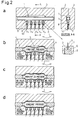
FIG. 2 is an explanatory view of a hydroforming apparatus of the present invention. -
FIG. 3 is an explanatory view of a hydroforming apparatus of the present invention. -
FIG. 4 is an explanatory view of the case where the metal tube initially in contact with the mold loses contact once together with the progress of the hydroforming. -
FIG. 5 is an explanatory view of a hydroform mold used in an embodiment of the present invention. -
FIG. 6 is an explanatory view of a load path of hydroforming used in an embodiment of the present invention. - The present invention will be explained taking as an example hydroforming in the case of expanding a metal tube having a circular cross-section as shown in
FIG. 2 into a rectangular cross-section. - The
metal tube 1 to be hydroformed is set inmolds metal tube 1 and the mold surfaces of themolds
At positions at the center of the surface in the non-contact direction (in the case of the present example, exactly the mating part of themolds 2 and 3), themold 2 andmold 3 are provided with holes 6 (in the present example, since exactly at the mold mating part, becoming grooves provided at the mating surfaces of themolds 2 and 3). The same is true for the later explainedholes 7 as well). - In the
holes 6,laser displacement meters 8 are mounted. At the locations where theholes 6 reach the surface of the inside of the mold,holes 7 through whichlasers 9 pass are formed. Theholes 7 are preferably extremely small from the viewpoint of hydroforming. By using thelaser displacement meters 8 to measure the distance from themetal tube 1, it is possible to accurately judge contact of themolds metal tube 1.
Among other sensors, quartz pressure sensors mounted at the inside of the mold (Patent Document 1) etc. can also detect contact with the metal tube, so are included in the contact sensors of the present invention. - After this, such
laser displacement meters 8 and theholes 6 etc. mounting them will be referred to all together as "contact sensors" in some cases.
In this example, as contact sensors, laser displacement meters were set at five locations (X1 to X5) at different cross-sections in the tube axial direction. - Next, the method of using the above contact sensors to find a suitable load path will be explained. Note that a schematic view of a suitable load path is shown in
FIG. 3 . - First, in the same way as the above method, without applying an axial pushing action, a fluid (for example, water) 5 is injected into the
metal tube 1 to raise only the internal pressure. However, in some cases, to prevent seal leakage from the tube ends, sometimes a slight axial pushing action is applied.
This initial pressure PH is the pressure at which the metal tube plastically deforms without cracking and is found relatively easily by calculation or experiments. - For example, the present inventors engaged in research and as a result learned that the yield starting pressure Pp in the planar strain state of the metal tube (see following formula (1)) can be used as a yardstick for the initial pressure PH (see Non-Patent Document 1).
Note that the "D" on the formula indicates the outside diameter of the stock tube (mm), "t" the wall thickness (mm), and "r" the r value, and "YS" and "YSp" indicate the 0.2% yield strengths in the single-axis tension state and planar strain state.
- However, when the shape is complicated etc., the error from the above formula becomes larger, so it is more reliable to find the initial pressure PH experimentally. Specifically, the initial pressure PH is set with reference to the pressure when cracking when raising the internal pressure until the metal tube cracks without applying an axial pushing action. For example, it is set to a pressure of 0.7 to 0.8 time the pressure at the time of cracking.
In the above way, the internal pressure is raised until the initial pressure PH found by calculation or experiment, but in this state, themetal tube 1 is not expanded much at all. - Next, the step where the internal pressure and axial pushing action are applied is entered, but with the method of the present invention, first, while holding the internal pressure at the initial pressure PH, the axial pushing
punch 4 is made to advance to apply only an axial pushing action.
As a result of research of the present inventors, even with a load of only an axial pushing action not raising the internal pressure, the metal tube is expanded, but in this case, not the center, but the end parts X1 and X5 are expanded the most.
Further, after the contact sensors at X1 and X5 detect contact, the axial pushing action is stopped (FIG. 2b and FIG. 3b). The process up to here is called the "first step". - After stopping the axial pushing action, only the internal pressure is raised. As a result of research of the inventors, when expanding the tube by only internal pressure without an axial pushing action, the tube is expanded from the center part rather than the end parts. In the case of the present example, X3 is expanded the most.
Further, when the contact sensor at X3 detects contact, it stops the increase in pressure (FIG. 2c and FIG. 3c). This step is called the "second step". - After this, while stopping the axial pushing action, the pressure is lowered once to the initial pressure PH. This process is called the "third step". Even if applying an axial pushing action without lowering the internal pressure, the pressure is too high, so the metal tube immediately ends up cracking.
- In the above way, after performing the first to third steps, the above steps are successively repeated from the above first step. The steps are ended when the contact sensors at all of the positions detect contact with the metal tube.
At this time, at the repeated first step, the progress of the axial pushing action is stopped when the contact sensors attached to the positions next closest to the tube ends detect contact of said metal tube. - In the case of the present example, at the time of finishing the processing steps up to here, X2 and X4 are not in contact. Therefore, at the repeated first step, the axial pushing action is applied again while maintaining the pressure PH and the axial pushing action is stopped after contact of X2 and X4 is detected.
In this case, the sensors at X2 and X4 are contact sensors mounted at said next closest positions, so as a result the time when X2 and X4 detect contact of the metal tube and the time when the contact sensors at all the positions detect contact match. For this reason, it is possible to end the steps at this point of time. - When, due to a long worked part or other reason, there is a contact sensor not in contact with the metal tube at this time, the second and third steps are executed. The first to third steps are similarly repeated until the contact sensors at all positions detect contact.
- By the above hydroforming method, the tube is uniformly expanded without buckling or wrinkles remaining over its entire length.
With the method of simultaneously increasing the axial pushing action and internal pressure as in the conventional method, the end parts are preferentially expanded. For this reason, with a shape of a part long in the tube axial direction, sometimes the center part is not expanded and buckling or wrinkles remain. - As opposed to this, with the method of the present invention, the end parts and the center part are alternately expanded, so are resistant to buckling or wrinkles remaining. In this point, the method is extremely advantageous.
Furthermore, at both the first step and both the second step, the parameter changed is just either of the axial pushing action or internal pressure, so finding the suitable conditions is extremely simple. This can also be said to be a major advantage of the present invention. - In the above hydroforming method, the present invention according to (2) was explained, but when the final predetermined shape is not reached by the steps up to there, for example corner, when desiring to form the corners sharply, only internal pressure is applied up to a high pressure (the present invention according to (3)).
- Further, the above working method may also be performed by manually controlling the increase and stopping of the internal pressure and the progress and stopping of the axial pushing action while viewing the results of detection of the contact sensors, but may also be performed by a hydroforming apparatus having a control means automatically detecting the results of detection of the sensors and automatically controlling the axial pushing action or internal pressure (the present invention according to the above (1)).
- Further, in the present example, the explanation was given of employing laser displacement meters for the contact sensors, but similar effects are obtained even if using other methods. For example, it is also possible to utilize the phenomenon of the change in stress and strain of the mold when the metal tube contacts the mold and attach quartz pressure sensors and strain gauges inside the mold. Further, contact type displacement meters etc. are also not a problem.
- The contact sensors are attached at positions where the mold and metal tube basically do not contact each other when the mold is set with the metal tube.
However, as shown inFIG. 4 , the metal tube, in the initial state, is set so as to contact the mold, but along with the progress of the hydroforming, sometimes it loses contact once with the mold. In such a case, the sensors should be mounted at such positions losing contact once along with progress. - In the example of
FIG. 4 , the center position of the inside of the bend of themetal tube 1 bent into a predetermined shape in advance, in the initial state, contacts themold 3 as shown inFIG. 4a , but temporarily loses contact in the middle of the progress of the hydroforming as shown inFIG. 4b . In this case, in the initial state, contact sensors are attached to locations before and after the center position inside the bend not contacting the metal tube and a contact sensor is attached at a location facing the center of the inside of the bend of themetal tube 1 contacting the mold in the initial state so as to enable detection of final contact with the mold. - Below, examples of the present invention will be shown.
- For the tube material, steel pipe of an outside diameter of 63.5 mm, a wall thickness of 2.0 mm, and a length of 700 mm (steel type: JIS standard STKM13B) was used. The material characteristics were a YS of 385 MPa and an r value of 0.9.
The hydroform mold was shaped expanded into a rectangular cross-section as shown inFIG. 5 . For the contact sensors, laser displacement meters were employed. As shown inFIG. 5 , they were set at five locations in the tube axial direction.
Further, in the same way as the detailed mounting drawing ofFIG. 2 , the mating faces of theupper mold 2 andlower mold 3 were cut to form grooves of widths of 88 mm and depths of 18 mm. In these,laser displacement meters 6 were attached. At the locations where the grooves reached the inside of the mold, grooves through whichlasers 9 pass are cut into the mating faces of theupper mold 2 andlower mold 3 to depths of 1 mm. - The load path of the hydroforming is shown in
FIG. 6 . First, the initial pressure PH was determined by the following procedure. If calculating the yield starting pressure Pp in the planar strain state by the above formula (1), it was 28.4 MPa. However, when actually raising the internal pressure until the steel pipe cracked without an axial pushing action, the pipe cracked at 26.5MPa. Accordingly, the initial pressure PH was set to 0.76 time the actual cracking pressure of 26.5 MPa, that is, 20 MPa. - Next, the inventors attempted to automatically find the load path using the system of the present invention without determining the conditions of the initial pressure on.
This being the case, as shown inFIG. 6 , if applying an axial pushing action by an internal pressure of a constant 20 MPa, thecontact sensors contact sensor 13 detected contact, the increase in pressure was automatically stopped. Note that the pressure at this time was 25.5 MPa. Further, after this, immediately the internal pressure fell to 20 MPa. Next, if applying the axial pushing action while holding the internal pressure at 20 MPa, thecontact sensors - Note that the cross-sectional shape in the present embodiment has a small corner roundness of 8 mm, so the final rise in pressure was also automatically applied. This final pressure was set to 150 MPa for working, whereupon the targeted roundness of 8 mm was also achieved, so this value was decided on.
- In the above way, the initial pressure and the final increased pressure were found by experiments, but the other parameters of the load path were all automatically found and defect-free hydroformed parts could be automatically worked. Note that the number of experiments when finding the initial pressure and final increased pressure were one each, so the labor involved did not pose that much of a burden. If a simple shape, a general idea can be obtained even by simple calculations.
- According to the present invention, finding a suitable load path for hydroforming becomes easy. Due to this, the number of manufacturers performing hydroforming will increase and the number of parts made using hydroforming will also increase. Accordingly, parts will be combined and the weight can be lightened. In particular, application to auto parts will lead to greater reductions in weight of vehicles and therefore improvement of fuel economy and as a result contribute to suppression of global warming. Further, the spread of hydroforming to industrial fields in which not much progress had been made in application in the past, for example, home electric appliance parts, furniture, construction machinery parts, motorcycle parts, building members, etc., can be expected as well.
-
- 1
- metal tube
- 2, 3
- hydroforming mold
- 4
- axial pushing punch
- 5
- fluid
- 6
- hole (groove) for mounting laser displacement meter
- 7
- hole (groove) for passage of laser
- 8 and 11 to 15
- laser displacement meters
- 9
- laser
- 10
- laser displacement meter cord
Claims (5)
- A hydroforming apparatus having a mold, axial pushing means, and internal pressure means applying internal pressure to a metal tube set in the mold to form it into a predetermined shape, wherein,
at the inside of said mold at locations not contacting said metal tube when said mold is set with said metal tube or said locations and locations no longer in contact along with progress of hydroforming, contact sensors able to judge contact with said metal tube are mounted at least at two different positions in the tube axial direction,
the apparatus has control means for controlling the axial pushing action and internal pressure by judgment of contact of said mold and said metal tube obtained by said contact sensors, and
said control means has the function of performing a first step of axially pushing tube ends in a state with the internal pressure held at a constant value and stopping the progress of the axial pushing action when judging that among the contact sensors not yet in contact with said metal tube, the contact sensors mounted at positions closest to the tube ends contact said metal tube, next performing a second step of raising only the internal pressure while leaving the positions of the tube ends fixed and stopping the increase in the internal pressure when judging contact by at least one of the sensors not yet in contact among said contact sensors, next performing a third step of lowering the internal pressure to the value before raising it while leaving the positions of the tube ends fixed, and repeating said first step to third step until all contact sensors judge contact. - A hydroforming apparatus as set forth in claim 1 characterized in that said metal tube is bent in advance into a predetermined shape, said contact sensors are mounted at the inside of said mold at locations facing the inside position of the bend of said metal tube which contact said metal tube when said metal tube is set, lose contact with said metal tube once along with the progress of the hydroforming, and finally contact said metal tube again, and further said contact sensors are mounted at least at one different position inside said mold at locations facing the inside of the bend before and after said inside position of the bend of said metal tube in the axial direction which are not in contact with said metal tube when said metal tube is set.
- A method for hydroforming, using a working apparatus having a mold, axial pushing means, and internal pressure means to apply internal pressure to a metal tube set in said mold so as to form it into a predetermined shape,
said method characterized by attaching contact sensors able to judge contact with said metal tube inside said mold at locations not contacting said metal tube at the time when said metal tube is set or said locations and locations which lose contact with said metal tube along with progress of hydroforming at least at two different positions in the tube axial direction,
performing a first step of axially pushing the tube ends in the state holding the internal pressure at a constant value and stopping the progress of the axial pushing action when contact sensors mounted at positions closest to the tube ends among said contact sensors not in contact with said metal tube judge contact with said metal tube,
next performing a second step of raising only the internal pressure while leaving the positions of the tube ends fixed and stopping the rise of internal pressure when at least one of the sensors not in contact among said contact sensors judge contact,
then performing a third step of lowering the internal pressure to the value before the rise while leaving the positions of the tube ends fixed,
then, after this, repeating said first step to third step until all of said contact sensors judge contact. - A method for hydroforming as set forth in claim 3 characterized in that said metal tube is bent in advance into a predetermined shape, mounting said contact sensors at the inside of said mold at locations facing the inside position of the bend of said metal tube which contact said metal tube when said metal tube is set, lose contact with said metal tube once along with the progress of the hydroforming, and finally contact said metal tube again, and further mounting said contact sensors at least at one different position inside said mold at locations facing the inside of the bend before and after said inside position of the bend of said metal tube in the axial direction which are not in contact with said metal tube when said metal tube is set.
- A method for hydroforming as set forth in claim 3 or 4 characterized by judging full contact of said contact sensor, then further raising only the internal pressure.
Applications Claiming Priority (2)
| Application Number | Priority Date | Filing Date | Title |
|---|---|---|---|
| JP2008175760A JP4374394B1 (en) | 2008-07-04 | 2008-07-04 | Hydroform processing apparatus and hydroform processing method |
| PCT/JP2009/062246 WO2010002017A1 (en) | 2008-07-04 | 2009-06-30 | Hydroforming equipment and hydroforming method |
Publications (3)
| Publication Number | Publication Date |
|---|---|
| EP2319634A1 true EP2319634A1 (en) | 2011-05-11 |
| EP2319634A4 EP2319634A4 (en) | 2013-08-28 |
| EP2319634B1 EP2319634B1 (en) | 2014-09-17 |
Family
ID=41459688
Family Applications (1)
| Application Number | Title | Priority Date | Filing Date |
|---|---|---|---|
| EP09773595.5A Not-in-force EP2319634B1 (en) | 2008-07-04 | 2009-06-30 | Hydroforming equipment and hydroforming method |
Country Status (8)
| Country | Link |
|---|---|
| US (1) | US8621904B2 (en) |
| EP (1) | EP2319634B1 (en) |
| JP (1) | JP4374394B1 (en) |
| KR (1) | KR101189264B1 (en) |
| CN (1) | CN102083564B (en) |
| BR (1) | BRPI0915613B1 (en) |
| CA (1) | CA2729415C (en) |
| WO (1) | WO2010002017A1 (en) |
Cited By (1)
| Publication number | Priority date | Publication date | Assignee | Title |
|---|---|---|---|---|
| CN103521587A (en) * | 2013-05-29 | 2014-01-22 | 上海汇众汽车制造有限公司 | Hydraulic forming sealing structure and hydraulic forming die push head sealing structure |
Families Citing this family (8)
| Publication number | Priority date | Publication date | Assignee | Title |
|---|---|---|---|---|
| JP6119197B2 (en) * | 2012-11-07 | 2017-04-26 | セイコーエプソン株式会社 | Liquid supply device, liquid supply device control method, and medical device system |
| EP2907598B1 (en) * | 2014-02-18 | 2016-06-15 | C.R.F. Società Consortile per Azioni | Method for manufacturing a camshaft for an internal combustion engine, by expanding a tubular element with a high pressure fluid and simultaneously compressing the tubular element axially |
| CN108687210B (en) * | 2018-05-03 | 2019-05-14 | 哈尔滨工业大学 | Method and system for size control of metal inner high pressure forming parts |
| CN111531790B (en) * | 2020-06-10 | 2021-11-23 | 合肥冠鸿光电科技有限公司 | Hardware injection mold automatic injection molding system capable of automatically detecting product |
| US11338352B2 (en) * | 2020-07-29 | 2022-05-24 | Rheem Manufacturing Company | Pressure expansion methods for heat exchanger manufacturing |
| CN111922173A (en) * | 2020-09-29 | 2020-11-13 | 浙大宁波理工学院 | Multi-stage omega-shaped pipe fluctuation internal high-pressure forming process |
| CN111922174A (en) * | 2020-10-16 | 2020-11-13 | 浙大宁波理工学院 | The device for high pressure forming inside the wave |
| EP4279194A1 (en) * | 2022-05-19 | 2023-11-22 | Braun GmbH | Personal care device and method of manufacturing a personal care device |
Family Cites Families (12)
| Publication number | Priority date | Publication date | Assignee | Title |
|---|---|---|---|---|
| JPH09314244A (en) | 1996-05-28 | 1997-12-09 | Kawasaki Steel Corp | Method and device for manufacturing tapered metal tube |
| US6128936A (en) * | 1998-09-09 | 2000-10-10 | Kabushiki Kaisha Opton | Bulging device and bulging method |
| US6322645B1 (en) * | 1999-09-24 | 2001-11-27 | William C. Dykstra | Method of forming a tubular blank into a structural component and die therefor |
| US20020162371A1 (en) * | 2001-05-01 | 2002-11-07 | Peter Hamstra | Method of pressure-ram-forming metal containers and the like |
| JP3809081B2 (en) | 2001-07-27 | 2006-08-16 | 独立行政法人科学技術振興機構 | Tube hydroforming apparatus and tube hydroforming method |
| JP2003311343A (en) | 2002-04-24 | 2003-11-05 | Jfe Steel Kk | Hydroform molding method and apparatus |
| CN1199746C (en) * | 2002-05-30 | 2005-05-04 | 佛山市佳能事液压机器制造有限公司 | Expanding method and equipment for implementing said expanding method |
| JP2004230433A (en) | 2003-01-31 | 2004-08-19 | Nisshin Steel Co Ltd | Method for hydroforming tubular body |
| CN1530189A (en) * | 2003-03-13 | 2004-09-22 | 钰捷工业股份有限公司 | Forming method of aluminum alloy pipe fitting |
| JP4590830B2 (en) | 2003-05-29 | 2010-12-01 | Jfeスチール株式会社 | Tube hydroforming loading path determination method, tube hydroforming apparatus, and metal member manufacturing method using them |
| US7191032B2 (en) * | 2004-05-14 | 2007-03-13 | Novelis Inc. | Methods of and apparatus for forming hollow metal articles |
| JP4625421B2 (en) | 2006-04-11 | 2011-02-02 | 新日本製鐵株式会社 | Hydroform processing method and apparatus |
-
2008
- 2008-07-04 JP JP2008175760A patent/JP4374394B1/en active Active
-
2009
- 2009-06-30 WO PCT/JP2009/062246 patent/WO2010002017A1/en not_active Ceased
- 2009-06-30 CA CA2729415A patent/CA2729415C/en not_active Expired - Fee Related
- 2009-06-30 EP EP09773595.5A patent/EP2319634B1/en not_active Not-in-force
- 2009-06-30 US US12/737,320 patent/US8621904B2/en active Active
- 2009-06-30 KR KR1020107028748A patent/KR101189264B1/en not_active Expired - Fee Related
- 2009-06-30 BR BRPI0915613-5A patent/BRPI0915613B1/en not_active IP Right Cessation
- 2009-06-30 CN CN200980125692XA patent/CN102083564B/en active Active
Non-Patent Citations (2)
| Title |
|---|
| No further relevant documents disclosed * |
| See also references of WO2010002017A1 * |
Cited By (2)
| Publication number | Priority date | Publication date | Assignee | Title |
|---|---|---|---|---|
| CN103521587A (en) * | 2013-05-29 | 2014-01-22 | 上海汇众汽车制造有限公司 | Hydraulic forming sealing structure and hydraulic forming die push head sealing structure |
| CN103521587B (en) * | 2013-05-29 | 2016-02-10 | 上海汇众汽车制造有限公司 | Hydroforming hermetically-sealed construction and mould are cut somebody's hair hermetically-sealed construction |
Also Published As
| Publication number | Publication date |
|---|---|
| CA2729415A1 (en) | 2010-01-07 |
| JP2010012498A (en) | 2010-01-21 |
| CA2729415C (en) | 2013-09-10 |
| JP4374394B1 (en) | 2009-12-02 |
| KR20110010651A (en) | 2011-02-01 |
| BRPI0915613B1 (en) | 2020-03-10 |
| US8621904B2 (en) | 2014-01-07 |
| CN102083564A (en) | 2011-06-01 |
| CN102083564B (en) | 2013-03-13 |
| EP2319634B1 (en) | 2014-09-17 |
| WO2010002017A1 (en) | 2010-01-07 |
| EP2319634A4 (en) | 2013-08-28 |
| KR101189264B1 (en) | 2012-10-09 |
| US20110120203A1 (en) | 2011-05-26 |
Similar Documents
| Publication | Publication Date | Title |
|---|---|---|
| EP2319634B1 (en) | Hydroforming equipment and hydroforming method | |
| US8281630B2 (en) | Method for hydroforming and a hydroformed product | |
| JP4478200B2 (en) | Hydroform processing method and hydroformed parts | |
| CN113624150B (en) | Method and device for acquiring bending strain of pipeline recess | |
| Abbasi et al. | Analytical method for prediction of weld line movement during stretch forming of tailor-welded blanks | |
| JP6805253B2 (en) | Methods for manufacturing sensors for high voltage lines and sensors for high voltage lines | |
| Ma et al. | Research and verification on neutral layer offset of bar in two-roll straightening process | |
| US20110155289A1 (en) | Residual stress improving method for pipe | |
| JP3756798B2 (en) | Metal pipe workability evaluation apparatus and evaluation method | |
| CN114964118B (en) | Pipeline depression detection method, processor and pipeline depression identification device | |
| CN102407425A (en) | Manufacturing method of marine steel ventilation steel pipe | |
| CN112257302B (en) | Method for constructing plate forming limit curve by adopting limit thickness | |
| Merklein et al. | Combined tube and double sheet hydroforming for the manufacturing of complex parts | |
| JP2006239741A (en) | Hydropiercing method, apparatus used therefor, and hydropiercing processed product | |
| KR20060068708A (en) | High precision hole expansion test device and test method using the same | |
| JP4625421B2 (en) | Hydroform processing method and apparatus | |
| Korkmaz et al. | Investigation of hydro-piercing method for stainless steels by finite element method | |
| JP2007237190A (en) | Mold for hydroforming | |
| Yang et al. | Experimental and numerical studies on the prediction of bendability limit of QSTE340 welded tube in NC bending process | |
| CN118136188B (en) | Full-plastic fracture design method for metal structure | |
| Liessem et al. | Methods for collapse pressure prediction of UOE linepipe | |
| Ram et al. | Investigation of hole expansion characteristics of DP 600 with testing and modeling | |
| Ceretti et al. | Steel and copper flow stress determination for THF applications | |
| Zhang et al. | Testing of additively manufactured stainless steel material and cross-sections | |
| CN119129040A (en) | A stress analysis method for girth welds in oil and gas pipeline hoisting construction |
Legal Events
| Date | Code | Title | Description |
|---|---|---|---|
| PUAI | Public reference made under article 153(3) epc to a published international application that has entered the european phase |
Free format text: ORIGINAL CODE: 0009012 |
|
| 17P | Request for examination filed |
Effective date: 20110113 |
|
| AK | Designated contracting states |
Kind code of ref document: A1 Designated state(s): AT BE BG CH CY CZ DE DK EE ES FI FR GB GR HR HU IE IS IT LI LT LU LV MC MK MT NL NO PL PT RO SE SI SK TR |
|
| AX | Request for extension of the european patent |
Extension state: AL BA RS |
|
| DAX | Request for extension of the european patent (deleted) | ||
| RAP1 | Party data changed (applicant data changed or rights of an application transferred) |
Owner name: NIPPON STEEL & SUMITOMO METAL CORPORATION |
|
| A4 | Supplementary search report drawn up and despatched |
Effective date: 20130730 |
|
| RIC1 | Information provided on ipc code assigned before grant |
Ipc: B21D 26/047 20110101ALI20130724BHEP Ipc: B21D 26/043 20110101ALI20130724BHEP Ipc: B21D 26/041 20110101AFI20130724BHEP |
|
| REG | Reference to a national code |
Ref country code: DE Ref legal event code: R079 Ref document number: 602009026745 Country of ref document: DE Free format text: PREVIOUS MAIN CLASS: B21D0026020000 Ipc: B21D0026041000 |
|
| GRAP | Despatch of communication of intention to grant a patent |
Free format text: ORIGINAL CODE: EPIDOSNIGR1 |
|
| RIC1 | Information provided on ipc code assigned before grant |
Ipc: B21D 26/041 20110101AFI20140120BHEP Ipc: B21D 26/043 20110101ALI20140120BHEP Ipc: B21D 26/047 20110101ALI20140120BHEP |
|
| INTG | Intention to grant announced |
Effective date: 20140220 |
|
| GRAP | Despatch of communication of intention to grant a patent |
Free format text: ORIGINAL CODE: EPIDOSNIGR1 |
|
| RIN1 | Information on inventor provided before grant (corrected) |
Inventor name: KURIYAMA, YUKIHISA Inventor name: MIZUMURA, MASAAKI Inventor name: WADA, MANABU Inventor name: SATO, KOICHI |
|
| GRAS | Grant fee paid |
Free format text: ORIGINAL CODE: EPIDOSNIGR3 |
|
| INTG | Intention to grant announced |
Effective date: 20140715 |
|
| GRAA | (expected) grant |
Free format text: ORIGINAL CODE: 0009210 |
|
| AK | Designated contracting states |
Kind code of ref document: B1 Designated state(s): AT BE BG CH CY CZ DE DK EE ES FI FR GB GR HR HU IE IS IT LI LT LU LV MC MK MT NL NO PL PT RO SE SI SK TR |
|
| REG | Reference to a national code |
Ref country code: GB Ref legal event code: FG4D |
|
| REG | Reference to a national code |
Ref country code: CH Ref legal event code: EP |
|
| REG | Reference to a national code |
Ref country code: IE Ref legal event code: FG4D |
|
| REG | Reference to a national code |
Ref country code: AT Ref legal event code: REF Ref document number: 687440 Country of ref document: AT Kind code of ref document: T Effective date: 20141015 |
|
| REG | Reference to a national code |
Ref country code: DE Ref legal event code: R096 Ref document number: 602009026745 Country of ref document: DE Effective date: 20141030 |
|
| PG25 | Lapsed in a contracting state [announced via postgrant information from national office to epo] |
Ref country code: GR Free format text: LAPSE BECAUSE OF FAILURE TO SUBMIT A TRANSLATION OF THE DESCRIPTION OR TO PAY THE FEE WITHIN THE PRESCRIBED TIME-LIMIT Effective date: 20141218 Ref country code: LT Free format text: LAPSE BECAUSE OF FAILURE TO SUBMIT A TRANSLATION OF THE DESCRIPTION OR TO PAY THE FEE WITHIN THE PRESCRIBED TIME-LIMIT Effective date: 20140917 Ref country code: NO Free format text: LAPSE BECAUSE OF FAILURE TO SUBMIT A TRANSLATION OF THE DESCRIPTION OR TO PAY THE FEE WITHIN THE PRESCRIBED TIME-LIMIT Effective date: 20141217 Ref country code: FI Free format text: LAPSE BECAUSE OF FAILURE TO SUBMIT A TRANSLATION OF THE DESCRIPTION OR TO PAY THE FEE WITHIN THE PRESCRIBED TIME-LIMIT Effective date: 20140917 Ref country code: SE Free format text: LAPSE BECAUSE OF FAILURE TO SUBMIT A TRANSLATION OF THE DESCRIPTION OR TO PAY THE FEE WITHIN THE PRESCRIBED TIME-LIMIT Effective date: 20140917 |
|
| REG | Reference to a national code |
Ref country code: NL Ref legal event code: VDEP Effective date: 20140917 |
|
| REG | Reference to a national code |
Ref country code: LT Ref legal event code: MG4D |
|
| PG25 | Lapsed in a contracting state [announced via postgrant information from national office to epo] |
Ref country code: LV Free format text: LAPSE BECAUSE OF FAILURE TO SUBMIT A TRANSLATION OF THE DESCRIPTION OR TO PAY THE FEE WITHIN THE PRESCRIBED TIME-LIMIT Effective date: 20140917 Ref country code: CY Free format text: LAPSE BECAUSE OF FAILURE TO SUBMIT A TRANSLATION OF THE DESCRIPTION OR TO PAY THE FEE WITHIN THE PRESCRIBED TIME-LIMIT Effective date: 20140917 Ref country code: HR Free format text: LAPSE BECAUSE OF FAILURE TO SUBMIT A TRANSLATION OF THE DESCRIPTION OR TO PAY THE FEE WITHIN THE PRESCRIBED TIME-LIMIT Effective date: 20140917 |
|
| REG | Reference to a national code |
Ref country code: AT Ref legal event code: MK05 Ref document number: 687440 Country of ref document: AT Kind code of ref document: T Effective date: 20140917 |
|
| PG25 | Lapsed in a contracting state [announced via postgrant information from national office to epo] |
Ref country code: NL Free format text: LAPSE BECAUSE OF FAILURE TO SUBMIT A TRANSLATION OF THE DESCRIPTION OR TO PAY THE FEE WITHIN THE PRESCRIBED TIME-LIMIT Effective date: 20140917 |
|
| PG25 | Lapsed in a contracting state [announced via postgrant information from national office to epo] |
Ref country code: EE Free format text: LAPSE BECAUSE OF FAILURE TO SUBMIT A TRANSLATION OF THE DESCRIPTION OR TO PAY THE FEE WITHIN THE PRESCRIBED TIME-LIMIT Effective date: 20140917 Ref country code: PT Free format text: LAPSE BECAUSE OF FAILURE TO SUBMIT A TRANSLATION OF THE DESCRIPTION OR TO PAY THE FEE WITHIN THE PRESCRIBED TIME-LIMIT Effective date: 20150119 Ref country code: ES Free format text: LAPSE BECAUSE OF FAILURE TO SUBMIT A TRANSLATION OF THE DESCRIPTION OR TO PAY THE FEE WITHIN THE PRESCRIBED TIME-LIMIT Effective date: 20140917 Ref country code: IS Free format text: LAPSE BECAUSE OF FAILURE TO SUBMIT A TRANSLATION OF THE DESCRIPTION OR TO PAY THE FEE WITHIN THE PRESCRIBED TIME-LIMIT Effective date: 20150117 Ref country code: CZ Free format text: LAPSE BECAUSE OF FAILURE TO SUBMIT A TRANSLATION OF THE DESCRIPTION OR TO PAY THE FEE WITHIN THE PRESCRIBED TIME-LIMIT Effective date: 20140917 Ref country code: RO Free format text: LAPSE BECAUSE OF FAILURE TO SUBMIT A TRANSLATION OF THE DESCRIPTION OR TO PAY THE FEE WITHIN THE PRESCRIBED TIME-LIMIT Effective date: 20140917 Ref country code: SK Free format text: LAPSE BECAUSE OF FAILURE TO SUBMIT A TRANSLATION OF THE DESCRIPTION OR TO PAY THE FEE WITHIN THE PRESCRIBED TIME-LIMIT Effective date: 20140917 |
|
| PG25 | Lapsed in a contracting state [announced via postgrant information from national office to epo] |
Ref country code: PL Free format text: LAPSE BECAUSE OF FAILURE TO SUBMIT A TRANSLATION OF THE DESCRIPTION OR TO PAY THE FEE WITHIN THE PRESCRIBED TIME-LIMIT Effective date: 20140917 Ref country code: AT Free format text: LAPSE BECAUSE OF FAILURE TO SUBMIT A TRANSLATION OF THE DESCRIPTION OR TO PAY THE FEE WITHIN THE PRESCRIBED TIME-LIMIT Effective date: 20140917 |
|
| REG | Reference to a national code |
Ref country code: DE Ref legal event code: R097 Ref document number: 602009026745 Country of ref document: DE |
|
| PLBE | No opposition filed within time limit |
Free format text: ORIGINAL CODE: 0009261 |
|
| STAA | Information on the status of an ep patent application or granted ep patent |
Free format text: STATUS: NO OPPOSITION FILED WITHIN TIME LIMIT |
|
| PG25 | Lapsed in a contracting state [announced via postgrant information from national office to epo] |
Ref country code: DK Free format text: LAPSE BECAUSE OF FAILURE TO SUBMIT A TRANSLATION OF THE DESCRIPTION OR TO PAY THE FEE WITHIN THE PRESCRIBED TIME-LIMIT Effective date: 20140917 |
|
| 26N | No opposition filed |
Effective date: 20150618 |
|
| PG25 | Lapsed in a contracting state [announced via postgrant information from national office to epo] |
Ref country code: SI Free format text: LAPSE BECAUSE OF FAILURE TO SUBMIT A TRANSLATION OF THE DESCRIPTION OR TO PAY THE FEE WITHIN THE PRESCRIBED TIME-LIMIT Effective date: 20140917 |
|
| PG25 | Lapsed in a contracting state [announced via postgrant information from national office to epo] |
Ref country code: MC Free format text: LAPSE BECAUSE OF FAILURE TO SUBMIT A TRANSLATION OF THE DESCRIPTION OR TO PAY THE FEE WITHIN THE PRESCRIBED TIME-LIMIT Effective date: 20140917 |
|
| REG | Reference to a national code |
Ref country code: CH Ref legal event code: PL |
|
| PG25 | Lapsed in a contracting state [announced via postgrant information from national office to epo] |
Ref country code: LU Free format text: LAPSE BECAUSE OF FAILURE TO SUBMIT A TRANSLATION OF THE DESCRIPTION OR TO PAY THE FEE WITHIN THE PRESCRIBED TIME-LIMIT Effective date: 20150630 |
|
| REG | Reference to a national code |
Ref country code: IE Ref legal event code: MM4A |
|
| PG25 | Lapsed in a contracting state [announced via postgrant information from national office to epo] |
Ref country code: CH Free format text: LAPSE BECAUSE OF NON-PAYMENT OF DUE FEES Effective date: 20150630 Ref country code: LI Free format text: LAPSE BECAUSE OF NON-PAYMENT OF DUE FEES Effective date: 20150630 Ref country code: IE Free format text: LAPSE BECAUSE OF NON-PAYMENT OF DUE FEES Effective date: 20150630 |
|
| REG | Reference to a national code |
Ref country code: FR Ref legal event code: PLFP Year of fee payment: 8 |
|
| PG25 | Lapsed in a contracting state [announced via postgrant information from national office to epo] |
Ref country code: MT Free format text: LAPSE BECAUSE OF FAILURE TO SUBMIT A TRANSLATION OF THE DESCRIPTION OR TO PAY THE FEE WITHIN THE PRESCRIBED TIME-LIMIT Effective date: 20140917 |
|
| REG | Reference to a national code |
Ref country code: FR Ref legal event code: PLFP Year of fee payment: 9 |
|
| PG25 | Lapsed in a contracting state [announced via postgrant information from national office to epo] |
Ref country code: HU Free format text: LAPSE BECAUSE OF FAILURE TO SUBMIT A TRANSLATION OF THE DESCRIPTION OR TO PAY THE FEE WITHIN THE PRESCRIBED TIME-LIMIT; INVALID AB INITIO Effective date: 20090630 Ref country code: BG Free format text: LAPSE BECAUSE OF FAILURE TO SUBMIT A TRANSLATION OF THE DESCRIPTION OR TO PAY THE FEE WITHIN THE PRESCRIBED TIME-LIMIT Effective date: 20140917 |
|
| PG25 | Lapsed in a contracting state [announced via postgrant information from national office to epo] |
Ref country code: TR Free format text: LAPSE BECAUSE OF FAILURE TO SUBMIT A TRANSLATION OF THE DESCRIPTION OR TO PAY THE FEE WITHIN THE PRESCRIBED TIME-LIMIT Effective date: 20140917 |
|
| PG25 | Lapsed in a contracting state [announced via postgrant information from national office to epo] |
Ref country code: BE Free format text: LAPSE BECAUSE OF FAILURE TO SUBMIT A TRANSLATION OF THE DESCRIPTION OR TO PAY THE FEE WITHIN THE PRESCRIBED TIME-LIMIT Effective date: 20140917 |
|
| REG | Reference to a national code |
Ref country code: FR Ref legal event code: PLFP Year of fee payment: 10 |
|
| PG25 | Lapsed in a contracting state [announced via postgrant information from national office to epo] |
Ref country code: MK Free format text: LAPSE BECAUSE OF FAILURE TO SUBMIT A TRANSLATION OF THE DESCRIPTION OR TO PAY THE FEE WITHIN THE PRESCRIBED TIME-LIMIT Effective date: 20140917 |
|
| REG | Reference to a national code |
Ref country code: DE Ref legal event code: R082 Ref document number: 602009026745 Country of ref document: DE Representative=s name: VOSSIUS & PARTNER PATENTANWAELTE RECHTSANWAELT, DE Ref country code: DE Ref legal event code: R081 Ref document number: 602009026745 Country of ref document: DE Owner name: NIPPON STEEL CORPORATION, JP Free format text: FORMER OWNER: NIPPON STEEL & SUMITOMO METAL CORP., TOKYO, JP |
|
| PGFP | Annual fee paid to national office [announced via postgrant information from national office to epo] |
Ref country code: DE Payment date: 20200617 Year of fee payment: 12 Ref country code: FR Payment date: 20200512 Year of fee payment: 12 |
|
| PGFP | Annual fee paid to national office [announced via postgrant information from national office to epo] |
Ref country code: IT Payment date: 20200512 Year of fee payment: 12 Ref country code: GB Payment date: 20200618 Year of fee payment: 12 |
|
| REG | Reference to a national code |
Ref country code: DE Ref legal event code: R119 Ref document number: 602009026745 Country of ref document: DE |
|
| GBPC | Gb: european patent ceased through non-payment of renewal fee |
Effective date: 20210630 |
|
| PG25 | Lapsed in a contracting state [announced via postgrant information from national office to epo] |
Ref country code: GB Free format text: LAPSE BECAUSE OF NON-PAYMENT OF DUE FEES Effective date: 20210630 Ref country code: DE Free format text: LAPSE BECAUSE OF NON-PAYMENT OF DUE FEES Effective date: 20220101 |
|
| PG25 | Lapsed in a contracting state [announced via postgrant information from national office to epo] |
Ref country code: FR Free format text: LAPSE BECAUSE OF NON-PAYMENT OF DUE FEES Effective date: 20210630 |
|
| PG25 | Lapsed in a contracting state [announced via postgrant information from national office to epo] |
Ref country code: IT Free format text: LAPSE BECAUSE OF NON-PAYMENT OF DUE FEES Effective date: 20210630 |