EP2319477A1 - Device for filing a flexible reservoir container in a negative pressure chamber - Google Patents
Device for filing a flexible reservoir container in a negative pressure chamber Download PDFInfo
- Publication number
- EP2319477A1 EP2319477A1 EP20090175262 EP09175262A EP2319477A1 EP 2319477 A1 EP2319477 A1 EP 2319477A1 EP 20090175262 EP20090175262 EP 20090175262 EP 09175262 A EP09175262 A EP 09175262A EP 2319477 A1 EP2319477 A1 EP 2319477A1
- Authority
- EP
- European Patent Office
- Prior art keywords
- flexible reservoir
- liquid
- container
- reservoir container
- separator
- Prior art date
- Legal status (The legal status is an assumption and is not a legal conclusion. Google has not performed a legal analysis and makes no representation as to the accuracy of the status listed.)
- Granted
Links
Images





Classifications
-
- B—PERFORMING OPERATIONS; TRANSPORTING
- B65—CONVEYING; PACKING; STORING; HANDLING THIN OR FILAMENTARY MATERIAL
- B65B—MACHINES, APPARATUS OR DEVICES FOR, OR METHODS OF, PACKAGING ARTICLES OR MATERIALS; UNPACKING
- B65B3/00—Packaging plastic material, semiliquids, liquids or mixed solids and liquids, in individual containers or receptacles, e.g. bags, sacks, boxes, cartons, cans, or jars
- B65B3/04—Methods of, or means for, filling the material into the containers or receptacles
- B65B3/10—Methods of, or means for, filling the material into the containers or receptacles by application of pressure to material
- B65B3/14—Methods of, or means for, filling the material into the containers or receptacles by application of pressure to material pneumatically
-
- A—HUMAN NECESSITIES
- A61—MEDICAL OR VETERINARY SCIENCE; HYGIENE
- A61M—DEVICES FOR INTRODUCING MEDIA INTO, OR ONTO, THE BODY; DEVICES FOR TRANSDUCING BODY MEDIA OR FOR TAKING MEDIA FROM THE BODY; DEVICES FOR PRODUCING OR ENDING SLEEP OR STUPOR
- A61M5/00—Devices for bringing media into the body in a subcutaneous, intra-vascular or intramuscular way; Accessories therefor, e.g. filling or cleaning devices, arm rests
- A61M5/14—Infusion devices, e.g. infusing by gravity; Blood infusion; Accessories therefor
- A61M5/142—Pressure infusion, e.g. using pumps
- A61M5/14244—Pressure infusion, e.g. using pumps adapted to be carried by the patient, e.g. portable on the body
-
- A—HUMAN NECESSITIES
- A61—MEDICAL OR VETERINARY SCIENCE; HYGIENE
- A61J—CONTAINERS SPECIALLY ADAPTED FOR MEDICAL OR PHARMACEUTICAL PURPOSES; DEVICES OR METHODS SPECIALLY ADAPTED FOR BRINGING PHARMACEUTICAL PRODUCTS INTO PARTICULAR PHYSICAL OR ADMINISTERING FORMS; DEVICES FOR ADMINISTERING FOOD OR MEDICINES ORALLY; BABY COMFORTERS; DEVICES FOR RECEIVING SPITTLE
- A61J1/00—Containers specially adapted for medical or pharmaceutical purposes
- A61J1/05—Containers specially adapted for medical or pharmaceutical purposes for collecting, storing or administering blood, plasma or medical fluids ; Infusion or perfusion containers
- A61J1/10—Bag-type containers
-
- A—HUMAN NECESSITIES
- A61—MEDICAL OR VETERINARY SCIENCE; HYGIENE
- A61J—CONTAINERS SPECIALLY ADAPTED FOR MEDICAL OR PHARMACEUTICAL PURPOSES; DEVICES OR METHODS SPECIALLY ADAPTED FOR BRINGING PHARMACEUTICAL PRODUCTS INTO PARTICULAR PHYSICAL OR ADMINISTERING FORMS; DEVICES FOR ADMINISTERING FOOD OR MEDICINES ORALLY; BABY COMFORTERS; DEVICES FOR RECEIVING SPITTLE
- A61J1/00—Containers specially adapted for medical or pharmaceutical purposes
- A61J1/14—Details; Accessories therefor
- A61J1/20—Arrangements for transferring or mixing fluids, e.g. from vial to syringe
- A61J1/2003—Accessories used in combination with means for transfer or mixing of fluids, e.g. for activating fluid flow, separating fluids, filtering fluid or venting
- A61J1/2068—Venting means
- A61J1/2075—Venting means for external venting
-
- A—HUMAN NECESSITIES
- A61—MEDICAL OR VETERINARY SCIENCE; HYGIENE
- A61J—CONTAINERS SPECIALLY ADAPTED FOR MEDICAL OR PHARMACEUTICAL PURPOSES; DEVICES OR METHODS SPECIALLY ADAPTED FOR BRINGING PHARMACEUTICAL PRODUCTS INTO PARTICULAR PHYSICAL OR ADMINISTERING FORMS; DEVICES FOR ADMINISTERING FOOD OR MEDICINES ORALLY; BABY COMFORTERS; DEVICES FOR RECEIVING SPITTLE
- A61J1/00—Containers specially adapted for medical or pharmaceutical purposes
- A61J1/14—Details; Accessories therefor
- A61J1/20—Arrangements for transferring or mixing fluids, e.g. from vial to syringe
- A61J1/2089—Containers or vials which are to be joined to each other in order to mix their contents
-
- A—HUMAN NECESSITIES
- A61—MEDICAL OR VETERINARY SCIENCE; HYGIENE
- A61M—DEVICES FOR INTRODUCING MEDIA INTO, OR ONTO, THE BODY; DEVICES FOR TRANSDUCING BODY MEDIA OR FOR TAKING MEDIA FROM THE BODY; DEVICES FOR PRODUCING OR ENDING SLEEP OR STUPOR
- A61M39/00—Tubes, tube connectors, tube couplings, valves, access sites or the like, specially adapted for medical use
- A61M39/10—Tube connectors or tube couplings
- A61M2039/1077—Adapters, e.g. couplings adapting a connector to one or several other connectors
-
- A—HUMAN NECESSITIES
- A61—MEDICAL OR VETERINARY SCIENCE; HYGIENE
- A61M—DEVICES FOR INTRODUCING MEDIA INTO, OR ONTO, THE BODY; DEVICES FOR TRANSDUCING BODY MEDIA OR FOR TAKING MEDIA FROM THE BODY; DEVICES FOR PRODUCING OR ENDING SLEEP OR STUPOR
- A61M39/00—Tubes, tube connectors, tube couplings, valves, access sites or the like, specially adapted for medical use
- A61M39/22—Valves or arrangement of valves
- A61M39/223—Multiway valves
- A61M2039/224—Multiway valves of the slide-valve type
-
- A—HUMAN NECESSITIES
- A61—MEDICAL OR VETERINARY SCIENCE; HYGIENE
- A61M—DEVICES FOR INTRODUCING MEDIA INTO, OR ONTO, THE BODY; DEVICES FOR TRANSDUCING BODY MEDIA OR FOR TAKING MEDIA FROM THE BODY; DEVICES FOR PRODUCING OR ENDING SLEEP OR STUPOR
- A61M2209/00—Ancillary equipment
- A61M2209/04—Tools for specific apparatus
- A61M2209/045—Tools for specific apparatus for filling, e.g. for filling reservoirs
-
- A—HUMAN NECESSITIES
- A61—MEDICAL OR VETERINARY SCIENCE; HYGIENE
- A61M—DEVICES FOR INTRODUCING MEDIA INTO, OR ONTO, THE BODY; DEVICES FOR TRANSDUCING BODY MEDIA OR FOR TAKING MEDIA FROM THE BODY; DEVICES FOR PRODUCING OR ENDING SLEEP OR STUPOR
- A61M5/00—Devices for bringing media into the body in a subcutaneous, intra-vascular or intramuscular way; Accessories therefor, e.g. filling or cleaning devices, arm rests
- A61M5/36—Devices for bringing media into the body in a subcutaneous, intra-vascular or intramuscular way; Accessories therefor, e.g. filling or cleaning devices, arm rests with means for eliminating or preventing injection or infusion of air into body
- A61M5/38—Devices for bringing media into the body in a subcutaneous, intra-vascular or intramuscular way; Accessories therefor, e.g. filling or cleaning devices, arm rests with means for eliminating or preventing injection or infusion of air into body using hydrophilic or hydrophobic filters
Definitions
- the invention relates to devices for transferring a liquid medicament from a supply container to a flexible reservoir container for use in an infusion pump device, a kit with such a device, and methods for transferring a liquid medicament from a supply container to a flexible reservoir container, according to the preamble of the independent claims.
- Devices for the automated release of liquid medicaments are normally used with patients who have a continuous and in the course of the day typically varying need of a medicine that can be administered by subcutaneous infusion.
- Specific applications are, for example, certain pain therapies and the treatment of diabetes, in which computer controlled infusion pump devices are used, such as insulin pumps.
- Such devices can be carried by a patient on the body, and contain a certain amount of liquid medicament in a medicine reservoir in the form of a container.
- the medicine reservoir often comprises medicine sufficient for one or several days.
- the liquid medicament is supplied to the patient's body from the medicine reservoir by subcutaneous infusion of injection, through an infusion cannula or an injection needle.
- the terms “medicament” and “liquid medicament” are meant to encompass any drug-containing liquid medicine, or therapeutic or diagnostic liquid, capable of being passed through a delivery element such as a hollow needle in a controlled manner, such as a liquid, solution, gel or fine suspension.
- Representative drugs include pharmaceuticals such as peptides, proteins, and hormones, biologically derived or active agents, hormonal and gene based agents, nutritional formulas and other substances in both solid (dispensed) or liquid form.
- medicament encompasses insulin preparations ready for administration.
- subcutaneous infusion and “subcutaneous injection” are meant to encompass any method in which a needle device is inserted at a selected site within the body of a patient for subcutaneous, intravenous, intramuscular or intradermal delivery of a liquid medicament to a subject.
- needle defines a piercing member (including an array of micro needles) adapted to be introduced into or through the skin of a subject.
- the patients using the medicament in question and administering it themselves by means of an infusion pump are increasingly emphasizing convenience and discretion.
- the dimensions of such infusion devices are limited, and particular the overall length, width and thickness should be as small as possible, in order not be evident through clothing and to be carried as comfortable as possible.
- Disposable cartridges are preferable for sterility and contamination prevention reasons. They may be delivered pre-filled with a certain liquid medicament, or empty, ready to be filled by a user. Said self-filling of containers has the advantage that also medicaments that are not readily available in pre-filled containers can be used for such infusion pump devices, thereby providing the patient with a larger choice of sources for his medicaments. Furthermore the stability of many medicaments in liquid form, particularly in plastic containers, can only be guaranteed by the manufacturer for some days.
- the standard infusion pump devices that are carried on or near the body have a medicine reservoir with a cylindrical ampoule and a displacement piston, which is pushed into the ampoule by a piston rod or threaded spindle in order to convey the liquid medicament.
- These known designs have the disadvantage of being longer and/or thicker than desired, the resulting dimensions being detrimental to the provision of compact infusion pumps.
- the syringe-type dosing mechanism can be replaced by a downstream pump system.
- a miniaturized pump is arranged downstream of the main reservoir, and causes a suction pressure that conveys the product from the reservoir to its destination.
- An example for such a pump is WO 2004/009162 A1 .
- the reservoir in such a type of an infusion pump device is realized as a flexible container.
- Such a flexible container may for example have the form of two flexible wall sheets that are sealed together.
- Flexible containers have the advantage of a smaller volume surplus of the container in relation to its content, which reduces the manufacture costs and the achievable dimensions of an infusion pump device using such a flexible container.
- the volume of a flexible container for use in an infusion pump device may be up to 10 ml, for example.
- a typical range for diabetes therapy is 1.5 to 3.5 ml.
- other therapies e.g. pain therapy, which require other administration regimes, other volume ranges may be more preferable.
- a common problem of flexible containers as they are known is air remaining in the container. If for example a flexible container is provided empty, and is filled with the appropriate liquid medicament by the user himself, there may be a certain amount of air in the container after the filling process. If said air remains in the container or in the fluidic system of a pump system, air bubbles may be administered instead of the liquid medicament, which leads to potentially dangerous dosing errors. Furthermore the administration of air into a patient's body should generally be avoided for medical reasons. Yet another negative effect of air present in the fluidic system of an infusion pump device is the reduced stiff ness of the fluidic system.
- US 2009/0163866 A1 shows an infusion system with a flexible reservoir container arranged in a rigid casing and fluidly connected to a liquid in a supply container under ambient pressure.
- a vacuum pump reduces the pressure inside of the rigid casing, the resulting pressure differential between the rigid casing and the supply container conveys the liquid into the flexible container.
- the user has to correctly orient the supply container. Since such a user regularly has no medical training, such a system is prone to incorrect operation and handling errors. Furthermore it is not possible to evacuate the flexible container prior to filling.
- One object of the invention is to provide an advantageous device for filling a flexible reservoir container with a liquid, particularly a liquid medicament, from supply container, such as for example a vial or an injection pen ampoule.
- a device according to the invention should allow the efficient and reproducible filling of a flexible container with a liquid medicament.
- Another object of the invention is to provide an advantageous device for filling a flexible reservoir container that is reusable to a large part.
- Yet another object of the invention is to provide an advantageous device for filling a flexible reservoir container that allows the removal of air that is already present in the flexible container.
- Such a device advantageously should prevent the entering of air bubbles into the flexible container.
- a device according to the invention should be producible with high quality at low costs in a large-scale manufacture.
- the compartment unit comprises a sealingly closable evacuation chamber, arranged for housing the flexible reservoir container and for being fluidly connected with a pump mechanism.
- the adapter unit comprises at least one transfer passage for transferring liquid from a supply container connected to the adapter unit to said flexible reservoir container.
- a separator is arranged in said transfer passage for separating gas bubbles from a liquid streaming through the transfer passage.
- the separation of the gas bubbles from the liquid stream in the separator is advantageously effected by a negative pressure in the chamber of the compartment unit.
- the separator can be fluidly connected to the chamber. It can comprise a liquid-impermeable, gas-permeable membrane that is on one side fluidly connected to the at least transfer passage and on the other side is fluidly connected to the chamber.
- the separator comprises a liquid-permeable, hydrophilic membrane or filter arranged in the at least one transfer passage.
- An advantageous embodiment of the device according to the invention comprises at least one vent passage for venting ambient air into the supply container.
- the device advantageously comprises a main valve and/or a flow restrictor arranged in the transfer passage upstream of the separator.
- the main valve can be controlled by the pressure in the chamber.
- the adapter unit of a device according to the invention is detachable and can be detachably secured and sealingly connected to the compartment unit.
- the compartment unit comprises two casing parts that can be detachably secured to each other, thereby forming the sealingly closed chamber.
- the adapter unit can be detachably secured to one of the casing parts of the compartment unit.
- One of the casing parts may provide a fluid connection of a flexible reservoir container arranged in the chamber with the transfer passage of the adapter unit.
- the device according to the invention can be equipped with a pump port or connector for fluidly connecting the chamber with a pump mechanism.
- the device also comprises a pump mechanism.
- a flexible reservoir container is mounted in the chamber.
- a kit according to the invention comprises a device according to the invention and one or more flexible reservoir containers.
- a kit comprises one or more casing parts, in which a flexible reservoir container can be mounted.
- the one or more flexible reservoir containers are provided mounted in the casing parts.
- the kit can comprise one or more syringes as a pump device.
- An advantageous method for transferring a liquid medicament from a supply container to a flexible reservoir container comprises the steps of: providing a fluid connection between the supply container and the flexible reservoir container; providing a separator arranged in the fluid connection for separating gas bubbles from the liquid; subjecting the flexible reservoir container to a reduced ambient pressure, thereby generating a negative pressure inside of the flexible reservoir container; sustaining normal ambient pressure inside of the supply container; subjecting the separator to said reduced ambient pressure, wherein the separation of the gas bubbles from the liquid in the separator is effected by the pressure difference between the liquid and the reduced ambient pressure; and conveying the liquid from the supply container to the flexible reservoir container, driven by the pressure difference between the inside of the supply container and the inside of the flexible reservoir container.
- the separator prior to filling the flexible reservoir container is evacuated via the separator.
- the separator is designed in such a way that the flexible reservoir container is fluidly connected to its surroundings with its reduced ambient pressure as long as the separator has not yet come into contact with liquid.
- FIG. 1 A basic embodiment of a device 1 according to the invention for transferring a liquid from a supply container 4 to a flexible reservoir container 5 is schematically shown in Figure 1 .
- the supply container 4 here a vial containing a liquid medicament such as e.g. insulin solution, is connected to an adapter unit 3 of the device 1, comprising a vent passage 32 and a transfer passage 31.
- the vent passage 32 comprises a first hollow needle 321 for penetrating a septum 41 of the supply container 4.
- the length of the first needle 321 is chosen such that in a bottom-orientation of the vial 4 the opening of the first needle is as high as possible, to reduce the generation of air bubbles when ambient air 72 is vented into the container 4 during the liquid transfer process.
- the tip of the first needle 321 is located above the liquid 71 phase also when the vial is yet completely filled.
- the first needle 321 is in fluid communication with a vent conduit 322 of the vent passage 32, opening toward ambient atmosphere 75.
- a filter such as a gas permeable membrane can be provided at the entry of the vent passage 32.
- the transfer passage 31 comprises a second hollow needle 311 for penetrating the septum 41 of the container 4.
- Said second needle is considerably shorter than the first needle 321, in order to ensure that in the applied bottom-up orientation the vial can be completely emptied. Furthermore a large distance between the openings of the first and second needle avoids the inadvertent transfer of vented air into the liquid transfer passage.
- a compartment unit 2 of the device 1 comprises a sealingly closed evacuation chamber 24, in which the flexible container 5 to be filled can be arranged and mounted.
- the initially empty flexible reservoir container 5 (dashed line) is connected with a transfer conduit 312 of the transfer passage 31, via a port 51 of the flexible reservoir container or the container 5 itself.
- the transfer passage 31 does not provide a direct connection between the supply container 4 and the flexible reservoir container 5.
- a gas-liquid separator 8 is arranged in the transfer passage 31 for separating gas bubbles from the stream of transferred liquid, and if necessary to branch off gas streaming through the transfer passage.
- a separator 8 comprises a gas-permeable membrane that is arranged in fluid connection to the transfer passage 31.
- the drain of the gas bubbles through the membrane is driven by a pressure differential across the membrane between the transfer passage 31 and the other side of the membrane, which for that purpose is in fluid connection 82 with the evacuation chamber 24.
- Said chamber 24 always provides a negative pressure during the transfer process.
- the transfer passage can also comprise a bubble trap in order to retain air bubbles in the liquid stream and to give the bubbles enough time to pass through the gas permeable membrane.
- a gas-liquid separator 8 as disclosed in WO 2006/047053 A1 , in which a gas-permeable membrane is arranged adjacent to a liquid-permeable membrane to allow the separation of liquid and gas.
- the gas-permeable membrane and the smaller liquid-permeable membrane are arranged in parallel, with a small gap separating them.
- the width of the gap is chosen in such a way that for energetic reasons air bubbles are prevented from entering the gap and covering the liquid-permeable membrane, in which case the mere suction force could urge the air bubble through the liquid-permeable membrane.
- the flexible reservoir container 5 is mounted in the evacuation chamber 24 of the compartment unit 2 and fluidly connected to the transfer conduit 312 of the transfer passage 31.
- a supply container 4 such as a vial with liquid medicament
- the adapter unit 3 is designed in such a way that the needles 321, 311 automatically penetrate the septum 41 when the supply container 4 is secured to the adapter unit 3, for example during insertion of the vial into a corresponding receptacle 34.
- the negative pressure can for example lie between about -250 mbar to about -850 mbar, and advantageously lies between -650 mbar and -750 mbar. The exact values depend on the particular embodiment of the device and the container to be filled, and may lie above or below the beforementioned values.
- the pump mechanism 6 can be embodied for example as a manually operated piston pump, or even simply as a syringe fluidly connected to the evacuation chamber 24. Alternatively the pump mechanism may be a motor-driven pump.
- the pump mechanism may be a motor-driven pump.
- the liquid stream 74 enters the second needle 311, passes the separator 8, where any air bubbles 73 carried along the stream 74 are diverted through the gas-permeable membrane 81 and degassing conduit 82 to the evacuation chamber 24, and flows into the flexible reservoir container 5.
- the flexible container 5 is inflated (black line).
- the transfer passage is blocked, for example by closing a valve arranged in the transfer passage, or the chamber venting valve 25 may be opened, thereby venting the evacuation chamber 24 and reducing the pressure differential to zero.
- the filled flexible reservoir container 5 is then ready for use in an infusion pump system.
- a check valve (not shown) may be arranged in the transfer passage 31, advantageously upstream of the separator 8.
- a mechanism is provided to inform a user when the negative pressure has reached the necessary value, particularly when the pump mechanism is actuated manually.
- a mechanism may for example give the user a visual or acoustical signal.
- FIG. 2 An alternative device according to the invention is shown in Figure 2 , suitable to work with an ampoule 4' with movable plug 43.
- Such ampoules are intended for the use with injection pen systems, particularly for insulin injection pens, and comprise a certain volume (e.g. 3 ml) of liquid medicament between a septum and a movable plug.
- Ambient pressure in the ampoule 4' is automatically sustained, since the movable plug 43 constantly reduces the volume of the ampoule during the draining of the ampoule.
- the venting passage 32 used in the embodiment of the device of Figure 1 is not necessary.
- Such an embodiment of a device according to the invention is particularly suitable because some manufacturers of liquid medicaments, particularly of insulin solutions, directly provide their products in such prefilled injection pen cartridges.
- a user of a device according to the invention can fill a flexible reservoir container with any suitable medicament, without a restriction of their choice of the most suitable product.
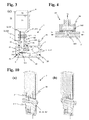
- FIG. 3(a) Another advantageous embodiment of a device according to the invention is schematically depicted in Figure 3(a) .
- the compartment unit 2 comprises two casing parts 21, 22 that are sealingly connected to form the evacuation chamber 24.
- one of the casing parts 21, 22 can be detached from the compartment unit 2, the flexible reservoir container is mounted, and the casing parts are reassembled.
- the adapter unit 3 is embodied as detachable unit that can be secured to the compartment unit 2 of the device, thereby establishing the necessary fluid connections between the port 51 of the flexible reservoir container, the separator 8 and transfer passage 31 of the adapter unit 3, and the evacuation chamber 24.
- a third hollow needle 313 is provided at the end of the transfer passage 31, which can penetrate a septum 511 arranged in the port 51 of the flexible reservoir container 5.
- the first hollow needle or pin 321 is longer than the second hollow needle 311, but does not reach the air phase 72.
- the distance of the tips of the needles 321, 311 is sufficient to prevent any air sucked directly from the vent passage 32 into the transfer passage, and air bubbles 73 flowing in through the first needle 322 ascend to the air phase 72.
- the entry into the venting conduit 322 is located above the maximum possible filling level of the vial 4. Thus no liquid 71 can emerge through the vent passage 32 even if no sucking pressure is applied to the transfer passage 31.
- the adapter unit 3 is designed such that when mounted to the compartment unit 2 a sealing 33 provided on the adapter unit 3 and/or the compartment unit 2 sealingly closes the evacuation chamber 24.
- a main valve 84 upstream of the separator 8 remains closed, and the inner volume of the flexible reservoir container 5 is evacuated via the temporary evacuation passage. Since there is a certain pressure drop over the two membranes of the separator 8, the pressure in the evacuation chamber 24 should advantageously be reduced slowly, in order to remain in a static regime where said pressure drop is irrelevant. Alternatively or additionally to a slow evacuation the pressure inside the evacuation chamber 24 may be increased again and the evacuation step repeated.
- the main valve 84 is opened. The liquid flows now from the supply container 4 through the transfer passage 31 to the flexible reservoir container 5.
- the liquid-permeable membrane 83 is wetted and becomes gas-impermeable.
- the temporary evacuation passage is now closed, and the primary function of the separator 8 is established.
- a main valve 84 is provided upstream of the separator 8, which allows to close the transfer passage 31.
- Such an embodiment does not only allow to stop the fluid transfer by closing the main valve, it also allows to delay the transfer of the liquid 71 in the supply container 4 to the flexible reservoir container 5. This feature eventually allows the evacuation of the flexible reservoir container 5 prior to the filling process, in order to reduce the amount of remaining air in the flexible reservoir container 5.
- a check valve 85 is provided, preventing any air or liquid in the transfer passage from flowing backwards.
- the two valves 84, 85 actually provide some redundancy.
- the check valve 85 ensures that even when a manipulation error with main valve 84 occurs, no liquid can flow back from the flexible reservoir container 5.
- the device would also work without the main valve 84 and only the check valve 85, although in such a case it would not be possible to evacuate the flexible reservoir container prior to the filling step.
- the above-mentioned embodiment is particularly advantageous in combination with a disposable adapter unit, in which after each filling procedure the detachable adapter unit, containing all potentially contaminated parts, is replaced.
- FIG. 3(b) An alternative embodiment of such a device 1 according to the invention is shown in Figure 3(b) .
- this embodiment comprises a flow restrictor 86.
- a flow restrictor can be realized e.g. as a meandering channel with a diameter of 50 to 250 micrometer, or a capillary. This allows an antecedent evacuation step without the need of an additional handling step of the user, as e.g. the actuation of the main valve 85 of the embodiment in Figure 3(a) .
- the evacuation chamber 24 has been evacuated with the pump mechanism 6, the liquid starts to flow from the supply container 4 into the transfer passage 31.
- the flow restrictor 86 the liquid stream is delayed for a certain time, which allows the remaining air in the flexible reservoir container 4 to be sucked into the evacuation chamber 24, before the liquid stream reaches the separator 8 and closes the temporary evacuation passage.
- FIG. 3(c) Yet another embodiment of a device 1 according to the invention is shown in Figure 3(c) .
- the user actuated main valve 84 of Figure 3(a) is replaced by a pressure controlled main valve 84', which is controlled by the pressure differential between the ambient atmosphere 75 and the evacuation chamber 24.
- a certain value for example -750 mbar.
- the main valve 84' opens automatically and the transfer process starts.
- the check valve 85 can be skipped. Since venting of the evacuation chamber 24 leads to a pressure drop, the pressure controlled valve 84' will automatically close, preventing the liquid from flowing backwards. Even if the supply container 4 is removed from the adapter unit 3 prior to venting the evacuation chamber 24, which does not immediately cause the valve 84' to close, ambient air will be sucked in into the evacuation chamber 24 via the needle 311, separator 8 and degassing conduit 82, preventing on one hand any liquid from flowing backwards and on the other hand slowly the venting the evacuation chamber 24. This finally causes the main valve 84' to close.
- FIG. 4 A possible embodiment of a pressure regulated valve 84' that can be used in the device shown in Figure 3(c) is given in Figure 4 .
- the valve 84' comprises a valve seat 843 arranged in a conduit of the transfer passage 31, and a valve member 842 in the form of a resilient elastic membrane arranged above the valve seat 843 and sealingly closing the conduit.
- the other side of the membrane 842 is in fluid communication 82 with the evacuation chamber 24 and thus subject to the pressure in the evacuation chamber.
- the resilient flexible membrane 842 is chosen such that when the pressure differential between the transfer passage 31 and the evacuation chamber 24 is below a certain value, the membrane 842 bulges and the liquid stream 74 can pass the valve 84'.
- FIG. 7 Yet another embodiment of a device 1 according to the invention is shown in an exploded view in Figure 7 .
- the device basically comprises a compartment unit 2 consisting of a first 21 and a second 22 casing part, and an adapter unit 3.
- the adapter unit 3 has an adapter casing 35 and an supply container receptacle 34, the latter being design to accommodate and secure a supply container 4 in the form of a vial, e.g. a standard insulin vial of 10 ml volume.
- a vial e.g. a standard insulin vial of 10 ml volume.
- a supply container 4 can be engaged to the adapter unit 3 with the neck 42 of the supply container 4 facing downwards.
- the neck is inserted into the supply container receptacle 34 in a generally linear fashion.
- the supply container 4 is centred and guided in the first part of the engagement movement.
- the first and second hollow needle (not visible) pierce the septum 41 of the supply container 4, thereby creating flow paths to the inside of the supply container 4.
- the supply container receptacle 34 may be provided with catches that engage with the neck of the supply container In the final part of the engagement movement.
- the casing 35 is essentially cylindrical in shape.
- the section oriented toward the compartment unit 2 forms a connector part 37, to be connected with a corresponding connector part 27 of the compartment unit 2.
- a circumferential sealing 33 provides an air tight connection between the adapter unit 3 and the compartment unit 2 when attached together.
- the sealing may for example be realized as an 0-ring or by two-component injection moulding, the sealing being made by the soft component.
- a first casing part 21 of the compartment unit 2 comprises a connector part 27 intended to interact with the adapter unit 3, in the form of an open cylinder into which the adapter connector part 37 can be inserted.
- a pump port 23 is provided for connecting the evacuation chamber 24 of the compartment unit 2 with an external pump mechanism 6, here embodied as a standard syringe 61. Syringes are inexpensive and thus provide a very suitable manually operated pump. Since no needle is needed, there is no risk of injuries.
- the pump port 23 can act as a venting valve 25, since when the syringe in inserted into the port, the chamber 24 is closed (venting valve 25 closed), and when the syringe is removed from the port, the chamber 24 communicates with the ambient atmosphere (venting valve 25 open).
- a second casing part 22 comprises a circumferential sealing 26. It also comprises a port 51 for connecting a flexible reservoir container (not shown) with the hollow pin 313 of the adapter unit 3. Simultaneously the port 51 is designed to secure the flexible reservoir container to the second casing part 22.
- the embodiment of a device 1 as shown in Figure 7 has several particular advantages. For hygienic reasons all parts of the device that come into contact with the liquid medicament advantageously are replaced after a single filling procedure. Since all these parts are located in the adapter unit 3, it is sufficient to design the adapter unit 3 as a disposable part, while the compartment unit 2 can be reused several times. This is particularly advantageous if the pump mechanism used is not a standard syringe but is somewhat more complicated, and thus more expensive.
- the second casing part 22 allows to mount of the flexible reservoir container 5 and to fluidly connect it 51 with the adapter unit 3. Thus at least the port 51 would have to be replaced together with the used disposable flexible reservoir container.
- the second casing part 22 then also acts as a part of the casing of the infusion pump device. After use, the casing part 22 and the emptied flexible reservoir container are disposed.
- a compartment unit 2 of a device 1 similar to the embodiment in Figure 7 is depicted in Figure 8 , in a perspective cross-sectional view with (a) a first casing part 21 and (b) a second casing part 22.
- the first 21 and second 22 casing parts each comprise a support structure 28, 28'.
- the support structure 28 is embodied as a curved wall with a plurality of venting conduits 281 in the form of holes.
- the wall 28 divides the evacuation chamber 24 formed by the two casing parts into two halves, a upper half above the wall 28, toward which the pump port 23 and the connector 27 are opening, and a lower half below the wall 28, in which the flexible reservoir container 5 is arranged.
- the surface of the wall facing the lower part of the evacuation chamber is concavely shaped.
- a similar hollow support structure 28' is provided in the second casing part 22, where the bottom of the casing wall is concave.
- a network of open channels 281' is provided on the support structure 28', which allows the communication of the negative pressure to the lower flexible reservoir container during all states of expansion.
- FIG 8(b) the completely empty flexible reservoir container 5 is shown, mounted to the second casing part 22.
- the flexible reservoir container 5 is clamped between the wall of the casing part 22 and an external port element 51.
- Said port element 51 is not an integral part of the flexible reservoir container 5 itself.
- the container is provided with holes in a peripheral sealing area (not visible), to prevent the screws from damaging the container hull.
- the port element 51 comprises a conduit 514 for fluidly connecting the transfer passage 31 of the adapter unit 3 with the flexible reservoir container.
- a septum 511 arranged in the conduit can be penetrated by a hollow needle or pin 313 of the transfer passage 31, thereby establishing a fluid connection.
- a circumferential sealing 512 provides a liquid-tight connection between the conduit 514 and an opening of the flexible reservoir container.
- the shown flexible reservoir container 5 is designed similar to the flexible container with a preformed fluid channel as known from the European patent application 08170627.7 of the applicants. Said applications also shows a clamp and connection system similar to the one formed by the casing part 22 and the port element 51.
- the outer rim 52 of the flexible reservoir container 5 lies on a circumferential edge of the bottom wall 28' of the casing part 22.
- the first casing part 21 is provided with a similar edge 282.
- the rim 52 of the flexible reservoir container is optionally secured between the edges of the support structures 28, 28'.
- the first casing part 21 is provided with a pump port 23 in fluid connection with the upper part of the evacuation chamber 24.
- the pump port comprises a check valve 251 to avoid venting of the evacuation chamber when the syringe 61 connected to the port 23 is removed.
- a second check valve may be provided that allows the exhaust of the air in the syringe 61 to the ambient atmosphere when the piston of the pump mechanism is pushed in. This would allow a user to perform several pumping strokes to evacuate the evacuation chamber 24, using a syringe with a smaller stroke volume.
- the support structure 28 may also be realized as a part of the second casing part 22. This has the advantage that when the first casing part is removed, the filled flexible reservoir container 5 is protected against accidental mechanical damages.
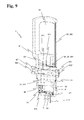
- FIG. 9 An advantageous embodiment of an adapter unit 3 of a device according to the invention is shown in a cross-section in Figure 9 .
- the supply container receptacle 34 has two access openings or windows 341 that allow a user to see the label of the inserted supply container.
- said windows 341 allow the user to easily grasp an inserted supply container and to remove it from the adapter unit 3.
- the hollow needles or pins 311, 321 of the vent passage 32 and the transfer passage 31 are arranged in a recess 342, thereby reducing the risk of an accidental injury by a user.
- the second needle 311 and the complete vent passage 32 are realized as metallic needles embedded in the body of the supply container receptacle 34, which is advantageously made of injection moulded plastic.
- the entry into the venting conduit 322 is located higher than the maximum possible liquid level of a supply container 4. Thus no liquid can flow out of the vent passage 32 even if no sucking pressure is applied to the transfer passage 31.
- the main valve 84 is realized as a slide valve mechanism 36 with a cylindrical slider 364 arranged in a bore of the adapter unit body.
- the valve is in a closed state.
- the needle 311 and the transfer conduit 312 are fluidly disconnected by a circumferential sealing 363.
- Two buttons 361, 361' are fastened to the slider 364 with screws 362, 362'. The two buttons act as stoppers for the slider that define the two working states (open and closed) of the main valve 84.
- FIG 10 schematically shows the adapter unit with a closed main valve 84 [ Figure 10(a) ] and with an open valve 84 [ Figure 10(b) ].
- the needle 311 and the transfer conduit 312 are fluidly connected via a conduit formed by a channel or groove (not visible) provided on the surface of the slider cylinder.
- the main valve may be provided with a biased spring element that automatically moves the slider back to a closed position when the user releases the valve.
- a check valve 85 is arranged in the transfer conduit 312.
- the transfer conduit then opens toward a separator 8, with a hydrophilic liquid-permeable membrane or filter 83 and a gas-permeable membrane 81, and finally ends in the third needle 313.
- the adapter unit 3 is built from a number of nested subunits. Sealing between the different subunits is achieved by circumferential sealings 314. The two membranes 81, 83 are mounted by sandwiching them between three subunits. In another variant the necessary sealings are achieved by welding the membranes to the adjacent subunits of the casing.
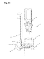
- a particularly suitable device 1 according to the invention is disclosed in Figure 11 , comprising the assembled compartment unit 2 of Figure 8 together with the adapter unit 3 in Figure 9 .
- a still empty flexible reservoir container 5 is mounted in the compartment unit 2.
- a syringe 61 is connected to the pump port 23 and acts as an external pumping mechanism 6.
- a first step the flexible reservoir container 5 is mounted in the second casing part 22 of the compartment unit 2, as shown in Figure 8(b) .
- a second step the first casing part 21 as shown in Figure 8(a) and the second casing part 22 are assembled, arriving at Figure 11 . It is irrelevant if the syringe 61 is connected to the compartment unit 2 before or after assembling the compartment unit 2.
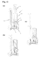
- the adapter unit 3 is inserted into the connector element 27 of the compartment unit 2, arriving at Figure 12(a) .
- the main valve 84 is closed.
- the vial 4 is inserted into the supply container receptacle 34, arriving at Figure 12(b) .
- the vial 4 may be inserted into the supply container receptacle 34 before the adapter unit 3 is secured to the compartment unit 2.
- a variant carries the risk that the user may accidentally actuate the main valve 84. Driven by gravity, the content of the vial could then flow along the transfer passage, prematurely wetting the separator, and finally being spilled.
- the piston of the syringe 61 is protracted. The main valve 84 remains closed. The pressure in the evacuation chamber 24 of the compartment unit is reduced, and any remaining air in the flexible reservoir container 5 is sucked into the evacuation chamber via the dry separator 8.
- the main valve 84 is opened by the user, which causes the liquid in the vial 4 to flow along the transfer passage 31 through the separator 8 into the flexible reservoir container 5. Simultaneously the vial 4 is vented through the venting passage 32.
- the flexible reservoir container 5 expands during the filling, and finally its wall sheets reach the support structures 28, 28' of the casing parts. Although there is still a remaining negative pressure, the expansion of the flexible reservoir container 5 is stopped, since its maximum volume is reached.
- the user then closes the valve 84, and removes adapter unit 3, thereby venting the evacuation chamber 24.
- the first, upper casing part 21 is removed.
- the filled flexible container may be detached from the second casing part 22 and inserted into an infusion pump system.
- the flexible reservoir container does not have an internal port.
- the flexible reservoir container 5 remains mounted to the second casing part 22 with is port 51, and is transferred together with the casing part 22 to the infusion pump system, where it is connected to the pump system via the port 51 of the second casing part 22.
- the second casing part 22 and port 51 can be reused as a casing part and connector port of the infusion pump system.
- FIG 13 a number of approaches for the design of the venting passage 32 and the transfer passage 31 of the adapter unit in interaction with a liquid filled vial 4 are shown.
- the tip of the first needle 321 is located in the liquid, while the tip of the venting conduit 322 is located equal or above the maximum surface level of the liquid in the vial 4.
- the liquid 71 cannot flow out of the vent passage 32 for hydrostatic reasons.
- This variant is similar to the one in Figures 3 and 9 .
- the tip of the first needle 321 is above the maximum surface level, similar to Figure 1 . Since no liquid can enter the needle 321, the venting conduit can be shorter, without restrictions to the position of the inlet of the venting conduit 322. This variant has the advantage that no air bubbles are produced. The longer needle, however, complicates the handling by a user.
- FIG. 13(c) A particularly advantageous variant is shown in Figure 13(c) .
- the first needle 321 is short, its tip being located in the liquid 71.
- a hydrophobic, gas-permeable membrane 323 is located at the inlet of the venting conduit. While air 72 can enter the inlet through the membrane 323, no liquid can flow out.
- a check valve 324 is located at the inlet of the of the venting conduit 322.
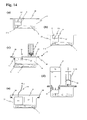
- FIG 14 Another embodiment of a device 1 according to the invention is disclosed in Figure 14 , in a simplified schematic way.
- the flexible reservoir container 5 is permanently mounted in a box-like second casing part 22.
- the flexible reservoir container 5 is equipped with an adapter unit 3 fluidly connected 313 to the flexible reservoir container 5.
- the needle 321 for the venting passage, the main valve 84, etc. are not shown.
- the adapter unit 3 and the empty flexible reservoir container 5 are sterilely packed in the casing part 22, which is covered by a removable cover 29.
- the casing part 22 may be provided with a peelable protective foil 29.
- the supply container / vial 4 with the liquid medicament 71 is inserted top-down into the adapter unit's supply container receptacle 34, and the user manually operates the piston pump 6 [ Figure 14(d) ].
- the negative pressure in the evacuation chamber 24 conveys the liquid 71 in the vial 24 through the adapter unit 3 into the flexible reservoir container 5.
- the evacuation chamber 24 is vented, and the durable elements 22, 6 of the device are removed for later use.
- the contaminated adapter unit 3 is disposed.
- the filled flexible reservoir container 5, still mounted in the second casing part 21, is then attached to an infusion pump system 9 [ Figure 14(e) ]. If the flexible reservoir container 5 is emptied, it is removed from the infusion pump device and disposed, together with the second casing part 22.
Landscapes
- Health & Medical Sciences (AREA)
- Engineering & Computer Science (AREA)
- Animal Behavior & Ethology (AREA)
- General Health & Medical Sciences (AREA)
- Biomedical Technology (AREA)
- Heart & Thoracic Surgery (AREA)
- Hematology (AREA)
- Life Sciences & Earth Sciences (AREA)
- Vascular Medicine (AREA)
- Anesthesiology (AREA)
- Public Health (AREA)
- Veterinary Medicine (AREA)
- Mechanical Engineering (AREA)
- Infusion, Injection, And Reservoir Apparatuses (AREA)
- Vacuum Packaging (AREA)
- Basic Packing Technique (AREA)
Abstract
Description
- The invention relates to devices for transferring a liquid medicament from a supply container to a flexible reservoir container for use in an infusion pump device, a kit with such a device, and methods for transferring a liquid medicament from a supply container to a flexible reservoir container, according to the preamble of the independent claims.
- Devices for the automated release of liquid medicaments are normally used with patients who have a continuous and in the course of the day typically varying need of a medicine that can be administered by subcutaneous infusion. Specific applications are, for example, certain pain therapies and the treatment of diabetes, in which computer controlled infusion pump devices are used, such as insulin pumps. Such devices can be carried by a patient on the body, and contain a certain amount of liquid medicament in a medicine reservoir in the form of a container. The medicine reservoir often comprises medicine sufficient for one or several days. The liquid medicament is supplied to the patient's body from the medicine reservoir by subcutaneous infusion of injection, through an infusion cannula or an injection needle.
- As used herein, the terms "medicament" and "liquid medicament" are meant to encompass any drug-containing liquid medicine, or therapeutic or diagnostic liquid, capable of being passed through a delivery element such as a hollow needle in a controlled manner, such as a liquid, solution, gel or fine suspension. Representative drugs include pharmaceuticals such as peptides, proteins, and hormones, biologically derived or active agents, hormonal and gene based agents, nutritional formulas and other substances in both solid (dispensed) or liquid form. In particular the term medicament encompasses insulin preparations ready for administration.
- The terms "subcutaneous infusion" and "subcutaneous injection" are meant to encompass any method in which a needle device is inserted at a selected site within the body of a patient for subcutaneous, intravenous, intramuscular or intradermal delivery of a liquid medicament to a subject. Further, the term needle defines a piercing member (including an array of micro needles) adapted to be introduced into or through the skin of a subject.
- Particularly in self-administration of liquid medicaments, for example insulin, the patients using the medicament in question and administering it themselves by means of an infusion pump are increasingly emphasizing convenience and discretion. As a consequence the dimensions of such infusion devices are limited, and particular the overall length, width and thickness should be as small as possible, in order not be evident through clothing and to be carried as comfortable as possible.
- While there are fully or partly disposable single-use infusion pump devices, such devices are typically non-disposable and are loaded with a disposable drug cartridge. Disposable cartridges are preferable for sterility and contamination prevention reasons. They may be delivered pre-filled with a certain liquid medicament, or empty, ready to be filled by a user. Said self-filling of containers has the advantage that also medicaments that are not readily available in pre-filled containers can be used for such infusion pump devices, thereby providing the patient with a larger choice of sources for his medicaments. Furthermore the stability of many medicaments in liquid form, particularly in plastic containers, can only be guaranteed by the manufacturer for some days.
- The standard infusion pump devices that are carried on or near the body have a medicine reservoir with a cylindrical ampoule and a displacement piston, which is pushed into the ampoule by a piston rod or threaded spindle in order to convey the liquid medicament. These known designs have the disadvantage of being longer and/or thicker than desired, the resulting dimensions being detrimental to the provision of compact infusion pumps.
- To reduce the overall volume of an infusion pump device the syringe-type dosing mechanism can be replaced by a downstream pump system. In such a device a miniaturized pump is arranged downstream of the main reservoir, and causes a suction pressure that conveys the product from the reservoir to its destination. An example for such a pump is
WO 2004/009162 A1 . Advantageously the reservoir in such a type of an infusion pump device is realized as a flexible container. Such a flexible container may for example have the form of two flexible wall sheets that are sealed together. Flexible containers have the advantage of a smaller volume surplus of the container in relation to its content, which reduces the manufacture costs and the achievable dimensions of an infusion pump device using such a flexible container. The volume of a flexible container for use in an infusion pump device may be up to 10 ml, for example. A typical range for diabetes therapy is 1.5 to 3.5 ml. For other therapies, e.g. pain therapy, which require other administration regimes, other volume ranges may be more preferable. - A common problem of flexible containers as they are known is air remaining in the container. If for example a flexible container is provided empty, and is filled with the appropriate liquid medicament by the user himself, there may be a certain amount of air in the container after the filling process. If said air remains in the container or in the fluidic system of a pump system, air bubbles may be administered instead of the liquid medicament, which leads to potentially dangerous dosing errors. Furthermore the administration of air into a patient's body should generally be avoided for medical reasons. Yet another negative effect of air present in the fluidic system of an infusion pump device is the reduced stiff ness of the fluidic system. Due to the high compressibility of gases such as air in relation to liquids such as water, it becomes difficult to detect blockages or occlusions in the fluidic system of an infusion pump device by measuring the fluidic pressure, because the air reduces the pressure increase that occurs in case of an occlusion.
- Filling a container with a liquid medicament with prior removal of air from the container and without having air bubbles getting into the container requires a considerable skill of a user. Said user is generally an untrained person, such as the patient himself or a relative. Reservoir containers can be filled by transferring the liquid medicament with a syringe. Syringes are typically inexpensive, but their proper use requires certain manual skills. Many patients with motor difficulties, such as diabetics with neuropathy or the elderly, have problems with the safely handling of syringes. In addition, accidental needle injuries and transferring the proper amount of medication are always a concern. Another problem is cross-contamination of medications between containers.
- Devices are known from the state of the art that should help a user to fill a container for infusion pump systems. Said devices, however, are intended for the use in syringe/ampoule type infusion pump systems, and cannot be properly used with flexible containers. Such filling devices are disclosed, among others, in
EP 1952837 A1 andEP 1820485 A1 . -
US 2009/0163866 A1 shows an infusion system with a flexible reservoir container arranged in a rigid casing and fluidly connected to a liquid in a supply container under ambient pressure. When a vacuum pump reduces the pressure inside of the rigid casing, the resulting pressure differential between the rigid casing and the supply container conveys the liquid into the flexible container. To avoid that air instead of liquid is sucked into the flexible container from the supply container, the user has to correctly orient the supply container. Since such a user regularly has no medical training, such a system is prone to incorrect operation and handling errors. Furthermore it is not possible to evacuate the flexible container prior to filling. - One object of the invention is to provide an advantageous device for filling a flexible reservoir container with a liquid, particularly a liquid medicament, from supply container, such as for example a vial or an injection pen ampoule. A device according to the invention should allow the efficient and reproducible filling of a flexible container with a liquid medicament.
- It is another object of this invention to provide an advantageous device that can be easily applied by users without medical training.
- Another object of the invention is to provide an advantageous device for filling a flexible reservoir container that is reusable to a large part.
- Yet another object of the invention is to provide an advantageous device for filling a flexible reservoir container that allows the removal of air that is already present in the flexible container.
- Furthermore such a device advantageously should prevent the entering of air bubbles into the flexible container.
- A device according to the invention should be producible with high quality at low costs in a large-scale manufacture.
- These and other objects are achieved by a device, a kit with such a device, and a method for transferring a liquid medicament from a supply container to a flexible reservoir container, according to the independent claims. Advantageous embodiments are given in the dependent claims.
- A device according to the invention for transferring a liquid medicament from a supply container to a flexible reservoir container has a compartment unit and an adapter unit. The compartment unit comprises a sealingly closable evacuation chamber, arranged for housing the flexible reservoir container and for being fluidly connected with a pump mechanism. The adapter unit comprises at least one transfer passage for transferring liquid from a supply container connected to the adapter unit to said flexible reservoir container. A separator is arranged in said transfer passage for separating gas bubbles from a liquid streaming through the transfer passage.
- The separation of the gas bubbles from the liquid stream in the separator is advantageously effected by a negative pressure in the chamber of the compartment unit. The separator can be fluidly connected to the chamber. It can comprise a liquid-impermeable, gas-permeable membrane that is on one side fluidly connected to the at least transfer passage and on the other side is fluidly connected to the chamber. Advantageously the separator comprises a liquid-permeable, hydrophilic membrane or filter arranged in the at least one transfer passage.
- An advantageous embodiment of the device according to the invention comprises at least one vent passage for venting ambient air into the supply container.
- The device advantageously comprises a main valve and/or a flow restrictor arranged in the transfer passage upstream of the separator. Optionally the main valve can be controlled by the pressure in the chamber.
- Advantageously the adapter unit of a device according to the invention is detachable and can be detachably secured and sealingly connected to the compartment unit.
- In another embodiment of such a device the compartment unit comprises two casing parts that can be detachably secured to each other, thereby forming the sealingly closed chamber. Advantageously the adapter unit can be detachably secured to one of the casing parts of the compartment unit. One of the casing parts may provide a fluid connection of a flexible reservoir container arranged in the chamber with the transfer passage of the adapter unit.
- The device according to the invention can be equipped with a pump port or connector for fluidly connecting the chamber with a pump mechanism. Advantageously the device also comprises a pump mechanism.
- In another advantageous embodiment a flexible reservoir container is mounted in the chamber.
- A kit according to the invention comprises a device according to the invention and one or more flexible reservoir containers. Advantageously such a kit comprises one or more casing parts, in which a flexible reservoir container can be mounted. In yet another embodiment the one or more flexible reservoir containers are provided mounted in the casing parts. The kit can comprise one or more syringes as a pump device.
- An advantageous method according to the invention for transferring a liquid medicament from a supply container to a flexible reservoir container (5) comprises the steps of: providing a fluid connection between the supply container and the flexible reservoir container; providing a separator arranged in the fluid connection for separating gas bubbles from the liquid; subjecting the flexible reservoir container to a reduced ambient pressure, thereby generating a negative pressure inside of the flexible reservoir container; sustaining normal ambient pressure inside of the supply container; subjecting the separator to said reduced ambient pressure, wherein the separation of the gas bubbles from the liquid in the separator is effected by the pressure difference between the liquid and the reduced ambient pressure; and conveying the liquid from the supply container to the flexible reservoir container, driven by the pressure difference between the inside of the supply container and the inside of the flexible reservoir container.
- In a variant to said method, prior to filling the flexible reservoir container is evacuated via the separator. The separator is designed in such a way that the flexible reservoir container is fluidly connected to its surroundings with its reduced ambient pressure as long as the separator has not yet come into contact with liquid.
- In order to facilitate a fuller understanding of the present invention, reference is now made to the appended drawings. These references should not be construed as limiting the present invention, but are intended to be exemplary only.
- Figure 1
- schematically shows a device according to the invention for transferring a liquid medica- ment from a supply container to a flexible reservoir container.
- Figure 2
- schematically shows an alternative device according to the invention for transferring a liquid medicament from a supply container to a flexible reservoir container.
- Figure 3
- schematically shows other embodiments of a device according to the invention with a detachable adapter unit.
- Figure 4
- shows a possible embodiment of a pressure controlled valve for use in a device according to
Figure 3(c) . - Figure 7
- shows a possible embodiment of a device according to the invention in an exploded view.
- Figure 8
- shows the casing part of a device similar to
Figure 7 , providing a hollow support structure limiting the expansion of a flexible reservoir container. - Figure 9
- shows an embodiment of an adapter unit of a device according to the invention in a cross- section.
- Figure 10
- schematically shows the adapter unit of
Figure 9 , in a closed state (a), and in an open state (b). - Figure 11
- shows a device according to the invention with the assembled compartment unit of
Figure 8 together with the adapter unit ofFigure 9 . - Figure 12
- shows in three consecutive steps the insertion of a vial into the assembled device of
Figure 11 and the evacuation of the chamber. - Figure 13
- shows different designs of the venting passage 32 and the
transfer passage 31 in interac- tion with a liquid filledvial 4. - Figure 14
- shows an alternative embodiment of a device according to the invention.
- A basic embodiment of a
device 1 according to the invention for transferring a liquid from asupply container 4 to aflexible reservoir container 5 is schematically shown inFigure 1 . Thesupply container 4, here a vial containing a liquid medicament such as e.g. insulin solution, is connected to anadapter unit 3 of thedevice 1, comprising a vent passage 32 and atransfer passage 31. - In the shown embodiment the vent passage 32 comprises a first
hollow needle 321 for penetrating aseptum 41 of thesupply container 4. The length of thefirst needle 321 is chosen such that in a bottom-orientation of thevial 4 the opening of the first needle is as high as possible, to reduce the generation of air bubbles whenambient air 72 is vented into thecontainer 4 during the liquid transfer process. Advantageously the tip of thefirst needle 321 is located above the liquid 71 phase also when the vial is yet completely filled. Thefirst needle 321 is in fluid communication with avent conduit 322 of the vent passage 32, opening towardambient atmosphere 75. To avoid any possible contamination of the vial content, a filter such as a gas permeable membrane can be provided at the entry of the vent passage 32. - The
transfer passage 31 comprises a secondhollow needle 311 for penetrating theseptum 41 of thecontainer 4. Said second needle is considerably shorter than thefirst needle 321, in order to ensure that in the applied bottom-up orientation the vial can be completely emptied. Furthermore a large distance between the openings of the first and second needle avoids the inadvertent transfer of vented air into the liquid transfer passage. - A
compartment unit 2 of thedevice 1 comprises a sealinglyclosed evacuation chamber 24, in which theflexible container 5 to be filled can be arranged and mounted. The initially empty flexible reservoir container 5 (dashed line) is connected with atransfer conduit 312 of thetransfer passage 31, via aport 51 of the flexible reservoir container or thecontainer 5 itself. - Particularly suitable and advantageous embodiments of flexible containers for use in such a device according to the invention are for example disclosed in European patent application No.
08167548.0 Figure 1 , ref. 51. However, any suitable type of flexible containers may be used. Particularly it is also possible to use flexible containers without an internal port that can be connected to an external connector acting as theport 51. Such solutions have been disclosed for example in European patent applications No.08170627.7 09155279.4 - To avoid the problems known from the state of the art, the
transfer passage 31 does not provide a direct connection between thesupply container 4 and theflexible reservoir container 5. To prevent the transfer of air bubbles or even larger amounts of air into theflexible reservoir container 5, a gas-liquid separator 8 is arranged in thetransfer passage 31 for separating gas bubbles from the stream of transferred liquid, and if necessary to branch off gas streaming through the transfer passage. In the simplest case such aseparator 8 comprises a gas-permeable membrane that is arranged in fluid connection to thetransfer passage 31. The drain of the gas bubbles through the membrane is driven by a pressure differential across the membrane between thetransfer passage 31 and the other side of the membrane, which for that purpose is influid connection 82 with theevacuation chamber 24. Saidchamber 24 always provides a negative pressure during the transfer process. The transfer passage can also comprise a bubble trap in order to retain air bubbles in the liquid stream and to give the bubbles enough time to pass through the gas permeable membrane. - Another possibility is the use of a gas-
liquid separator 8 as disclosed inWO 2006/047053 A1 , in which a gas-permeable membrane is arranged adjacent to a liquid-permeable membrane to allow the separation of liquid and gas. The gas-permeable membrane and the smaller liquid-permeable membrane are arranged in parallel, with a small gap separating them. The width of the gap is chosen in such a way that for energetic reasons air bubbles are prevented from entering the gap and covering the liquid-permeable membrane, in which case the mere suction force could urge the air bubble through the liquid-permeable membrane. - During normal use of the
device 1 according to the invention shown inFigure 1 , in a first step theflexible reservoir container 5 is mounted in theevacuation chamber 24 of thecompartment unit 2 and fluidly connected to thetransfer conduit 312 of thetransfer passage 31. Then subsequently asupply container 4, such as a vial with liquid medicament, is connected with theadapter unit 3, by penetrating theseptum 41 of the vial with the first 321 and second 311 hollow needle. Advantageously theadapter unit 3 is designed in such a way that theneedles septum 41 when thesupply container 4 is secured to theadapter unit 3, for example during insertion of the vial into a correspondingreceptacle 34. - If not yet happened the
evacuation chamber 24 is now sealingly closed and thechamber venting valve 25 is closed. Then thepump mechanism 6 is actuated, reducing the pressure inside of theevacuation chamber 24. The negative pressure can for example lie between about -250 mbar to about -850 mbar, and advantageously lies between -650 mbar and -750 mbar. The exact values depend on the particular embodiment of the device and the container to be filled, and may lie above or below the beforementioned values. - The
pump mechanism 6 can be embodied for example as a manually operated piston pump, or even simply as a syringe fluidly connected to theevacuation chamber 24. Alternatively the pump mechanism may be a motor-driven pump. As a result of the negative pressure inside of theevacuation chamber 24, the higher ambient pressure in the vial propels the liquid 71 via thetransfer passage 31 into theflexible container 5, while ambient air is constantly vented into the vial via the vent passage 32. Theliquid stream 74 enters thesecond needle 311, passes theseparator 8, where any air bubbles 73 carried along thestream 74 are diverted through the gas-permeable membrane 81 anddegassing conduit 82 to theevacuation chamber 24, and flows into theflexible reservoir container 5. During filling theflexible container 5 is inflated (black line). - To finish the transfer process, either the transfer passage is be blocked, for example by closing a valve arranged in the transfer passage, or the
chamber venting valve 25 may be opened, thereby venting theevacuation chamber 24 and reducing the pressure differential to zero. The filledflexible reservoir container 5 is then ready for use in an infusion pump system. - When the flexible reservoir container is filled, its walls are under a certain strain, which leads to certain over pressure in the flexible reservoir container. To prevent that any liquid may flow out of the filled
flexible reservoir container 5 though thetransfer passage 31 when the negative pressure in thechamber 24 is removed, a check valve (not shown) may be arranged in thetransfer passage 31, advantageously upstream of theseparator 8. - In some embodiment a mechanism is provided to inform a user when the negative pressure has reached the necessary value, particularly when the pump mechanism is actuated manually. Such a mechanism may for example give the user a visual or acoustical signal.
- An alternative device according to the invention is shown in
Figure 2 , suitable to work with an ampoule 4' withmovable plug 43. Such ampoules are intended for the use with injection pen systems, particularly for insulin injection pens, and comprise a certain volume (e.g. 3 ml) of liquid medicament between a septum and a movable plug. Ambient pressure in the ampoule 4' is automatically sustained, since themovable plug 43 constantly reduces the volume of the ampoule during the draining of the ampoule. As a result the venting passage 32 used in the embodiment of the device ofFigure 1 is not necessary. - Such an embodiment of a device according to the invention is particularly suitable because some manufacturers of liquid medicaments, particularly of insulin solutions, directly provide their products in such prefilled injection pen cartridges. Thus a user of a device according to the invention can fill a flexible reservoir container with any suitable medicament, without a restriction of their choice of the most suitable product.
- Another advantageous embodiment of a device according to the invention is schematically depicted in
Figure 3(a) . Thecompartment unit 2 comprises twocasing parts evacuation chamber 24. Thus for mounting theflexible reservoir container 5 one of thecasing parts compartment unit 2, the flexible reservoir container is mounted, and the casing parts are reassembled. - The
adapter unit 3 is embodied as detachable unit that can be secured to thecompartment unit 2 of the device, thereby establishing the necessary fluid connections between theport 51 of the flexible reservoir container, theseparator 8 and transferpassage 31 of theadapter unit 3, and theevacuation chamber 24. A thirdhollow needle 313 is provided at the end of thetransfer passage 31, which can penetrate aseptum 511 arranged in theport 51 of theflexible reservoir container 5. - The first hollow needle or
pin 321 is longer than the secondhollow needle 311, but does not reach theair phase 72. The distance of the tips of theneedles first needle 322 ascend to theair phase 72. The entry into the ventingconduit 322 is located above the maximum possible filling level of thevial 4. Thus no liquid 71 can emerge through the vent passage 32 even if no sucking pressure is applied to thetransfer passage 31. - The
adapter unit 3 is designed such that when mounted to the compartment unit 2 a sealing 33 provided on theadapter unit 3 and/or thecompartment unit 2 sealingly closes theevacuation chamber 24. - A liquid-permeable membrane or filter of a
separator 8 for use with aqueous solutions, as which liquid medicaments are normally provided, advantageously consists of a hydrophilic material that, when wetted, effectively prevents the passage or air bubbles due to interface tension. As long as such a liquid-permeable membrane of filter is still dry, however, it remains permeable for air. With such an embodiment of adevice 1 according to the invention thus an evacuation step can precede the liquid transfer step. Since the liquid-permeable membrane is not yet wetted and still gas-permeable, theflexible reservoir container 5 is in fluid communication with theevacuation chamber 24, via a temporary evacuation passage comprisingthird needle 313,transfer conduit 312,separator 8, and degassingconduit 82. - When
evacuation chamber 24 is evacuated with thepump mechanism 6, amain valve 84 upstream of theseparator 8 remains closed, and the inner volume of theflexible reservoir container 5 is evacuated via the temporary evacuation passage. Since there is a certain pressure drop over the two membranes of theseparator 8, the pressure in theevacuation chamber 24 should advantageously be reduced slowly, in order to remain in a static regime where said pressure drop is irrelevant. Alternatively or additionally to a slow evacuation the pressure inside theevacuation chamber 24 may be increased again and the evacuation step repeated. When theflexible reservoir container 5 is completely evacuated, themain valve 84 is opened. The liquid flows now from thesupply container 4 through thetransfer passage 31 to theflexible reservoir container 5. When the liquid passes theseparator 8 the liquid-permeable membrane 83 is wetted and becomes gas-impermeable. The temporary evacuation passage is now closed, and the primary function of theseparator 8 is established. - In the embodiment shown in
Figure 3(a) amain valve 84 is provided upstream of theseparator 8, which allows to close thetransfer passage 31. Such an embodiment does not only allow to stop the fluid transfer by closing the main valve, it also allows to delay the transfer of the liquid 71 in thesupply container 4 to theflexible reservoir container 5. This feature eventually allows the evacuation of theflexible reservoir container 5 prior to the filling process, in order to reduce the amount of remaining air in theflexible reservoir container 5. - In addition to the main valve 84 a
check valve 85 is provided, preventing any air or liquid in the transfer passage from flowing backwards. The twovalves check valve 85 ensures that even when a manipulation error withmain valve 84 occurs, no liquid can flow back from theflexible reservoir container 5. The device would also work without themain valve 84 and only thecheck valve 85, although in such a case it would not be possible to evacuate the flexible reservoir container prior to the filling step. - Since once the
separator 8 is wetted the temporary evacuation passage is irreversibly closed, the above-mentioned embodiment is particularly advantageous in combination with a disposable adapter unit, in which after each filling procedure the detachable adapter unit, containing all potentially contaminated parts, is replaced. - An alternative embodiment of such a
device 1 according to the invention is shown inFigure 3(b) . Instead of a main valve this embodiment comprises aflow restrictor 86. Such a flow restrictor can be realized e.g. as a meandering channel with a diameter of 50 to 250 micrometer, or a capillary. This allows an antecedent evacuation step without the need of an additional handling step of the user, as e.g. the actuation of themain valve 85 of the embodiment inFigure 3(a) . After theevacuation chamber 24 has been evacuated with thepump mechanism 6, the liquid starts to flow from thesupply container 4 into thetransfer passage 31. In theflow restrictor 86 the liquid stream is delayed for a certain time, which allows the remaining air in theflexible reservoir container 4 to be sucked into theevacuation chamber 24, before the liquid stream reaches theseparator 8 and closes the temporary evacuation passage. - Yet another embodiment of a
device 1 according to the invention is shown inFigure 3(c) . In that particular embodiment the user actuatedmain valve 84 ofFigure 3(a) is replaced by a pressure controlled main valve 84', which is controlled by the pressure differential between theambient atmosphere 75 and theevacuation chamber 24. When theflexible reservoir container 5 is sufficiently evacuated the negative pressure reaches a certain value, for example -750 mbar. The main valve 84' opens automatically and the transfer process starts. Such an embodiment thus reduces the handlings steps of a user to a minimum, while at the same time reproducibly controlling the evacuation and filling of the flexible reservoir container. - In an alternative variant the
check valve 85 can be skipped. Since venting of theevacuation chamber 24 leads to a pressure drop, the pressure controlled valve 84' will automatically close, preventing the liquid from flowing backwards. Even if thesupply container 4 is removed from theadapter unit 3 prior to venting theevacuation chamber 24, which does not immediately cause the valve 84' to close, ambient air will be sucked in into theevacuation chamber 24 via theneedle 311,separator 8 anddegassing conduit 82, preventing on one hand any liquid from flowing backwards and on the other hand slowly the venting theevacuation chamber 24. This finally causes the main valve 84' to close. - A possible embodiment of a pressure regulated valve 84' that can be used in the device shown in
Figure 3(c) is given inFigure 4 . The valve 84' comprises avalve seat 843 arranged in a conduit of thetransfer passage 31, and avalve member 842 in the form of a resilient elastic membrane arranged above thevalve seat 843 and sealingly closing the conduit. The other side of themembrane 842 is influid communication 82 with theevacuation chamber 24 and thus subject to the pressure in the evacuation chamber. The resilientflexible membrane 842 is chosen such that when the pressure differential between thetransfer passage 31 and theevacuation chamber 24 is below a certain value, themembrane 842 bulges and theliquid stream 74 can pass the valve 84'. - Yet another embodiment of a
device 1 according to the invention is shown in an exploded view inFigure 7 . The device basically comprises acompartment unit 2 consisting of a first 21 and a second 22 casing part, and anadapter unit 3. - The
adapter unit 3 has anadapter casing 35 and ansupply container receptacle 34, the latter being design to accommodate and secure asupply container 4 in the form of a vial, e.g. a standard insulin vial of 10 ml volume. - A
supply container 4 can be engaged to theadapter unit 3 with theneck 42 of thesupply container 4 facing downwards. The neck is inserted into thesupply container receptacle 34 in a generally linear fashion. Thesupply container 4 is centred and guided in the first part of the engagement movement. During engagement, the first and second hollow needle (not visible) pierce theseptum 41 of thesupply container 4, thereby creating flow paths to the inside of thesupply container 4. In addition thesupply container receptacle 34 may be provided with catches that engage with the neck of the supply container In the final part of the engagement movement. - The
casing 35 is essentially cylindrical in shape. The section oriented toward thecompartment unit 2 forms aconnector part 37, to be connected with acorresponding connector part 27 of thecompartment unit 2. A circumferential sealing 33 provides an air tight connection between theadapter unit 3 and thecompartment unit 2 when attached together. The sealing may for example be realized as an 0-ring or by two-component injection moulding, the sealing being made by the soft component. - A
first casing part 21 of thecompartment unit 2 comprises aconnector part 27 intended to interact with theadapter unit 3, in the form of an open cylinder into which theadapter connector part 37 can be inserted. Apump port 23 is provided for connecting theevacuation chamber 24 of thecompartment unit 2 with anexternal pump mechanism 6, here embodied as a standard syringe 61. Syringes are inexpensive and thus provide a very suitable manually operated pump. Since no needle is needed, there is no risk of injuries. - In interaction with the syringe 61 the
pump port 23 can act as a ventingvalve 25, since when the syringe in inserted into the port, thechamber 24 is closed (ventingvalve 25 closed), and when the syringe is removed from the port, thechamber 24 communicates with the ambient atmosphere (ventingvalve 25 open). - A
second casing part 22 comprises acircumferential sealing 26. It also comprises aport 51 for connecting a flexible reservoir container (not shown) with thehollow pin 313 of theadapter unit 3. Simultaneously theport 51 is designed to secure the flexible reservoir container to thesecond casing part 22. - The embodiment of a
device 1 as shown inFigure 7 has several particular advantages. For hygienic reasons all parts of the device that come into contact with the liquid medicament advantageously are replaced after a single filling procedure. Since all these parts are located in theadapter unit 3, it is sufficient to design theadapter unit 3 as a disposable part, while thecompartment unit 2 can be reused several times. This is particularly advantageous if the pump mechanism used is not a standard syringe but is somewhat more complicated, and thus more expensive. - In the shown embodiment the
second casing part 22 allows to mount of theflexible reservoir container 5 and to fluidly connect it 51 with theadapter unit 3. Thus at least theport 51 would have to be replaced together with the used disposable flexible reservoir container. However, it is advantageous to transfer the filledflexible reservoir container 5 to its destination in an infusion pump device while still mounted on thesecond casing part 22, since the rigid structure of thecasing 22 protects the flexible reservoir container and simplifies the handling for the user. In the infusion pump device thesecond casing part 22 then also acts as a part of the casing of the infusion pump device. After use, thecasing part 22 and the emptied flexible reservoir container are disposed. - A
compartment unit 2 of adevice 1 similar to the embodiment inFigure 7 is depicted inFigure 8 , in a perspective cross-sectional view with (a) afirst casing part 21 and (b) asecond casing part 22. In order to limit the expansion of aflexible reservoir container 5 during the filling process, thereby on one hand reproducibly defining a maximum filling volume and the other hand preventing an accidental damage of the flexible reservoir container due to overfilling, the first 21 and second 22 casing parts each comprise asupport structure 28, 28'. - In the
first casing part 21 thesupport structure 28 is embodied as a curved wall with a plurality of ventingconduits 281 in the form of holes. Thewall 28 divides theevacuation chamber 24 formed by the two casing parts into two halves, a upper half above thewall 28, toward which thepump port 23 and theconnector 27 are opening, and a lower half below thewall 28, in which theflexible reservoir container 5 is arranged. The surface of the wall facing the lower part of the evacuation chamber is concavely shaped. When the evacuation chamber is evacuated, the air in the lower half is sucked through theholes 281 into the upper half and from there to thepump mechanism 6. The volume of the upper half provides the necessary negative pressure reservoir when theflexible reservoir container 5 is filled, and finally the volume of the lower half of the evacuation chamber decreases to essentially zero. - A similar hollow support structure 28' is provided in the
second casing part 22, where the bottom of the casing wall is concave. In order to allow the complete expansion of theflexible reservoir container 5 towards the support structure 28', a network of open channels 281' is provided on the support structure 28', which allows the communication of the negative pressure to the lower flexible reservoir container during all states of expansion. - In
Figure 8(b) the completely emptyflexible reservoir container 5 is shown, mounted to thesecond casing part 22. Theflexible reservoir container 5 is clamped between the wall of thecasing part 22 and anexternal port element 51. Saidport element 51 is not an integral part of theflexible reservoir container 5 itself. Twoscrews 513, one of which is visible, secure theport element 51 to thecasing part 22, thereby clamping a corner of theflexible reservoir container 5. The container is provided with holes in a peripheral sealing area (not visible), to prevent the screws from damaging the container hull. - The
port element 51 comprises aconduit 514 for fluidly connecting thetransfer passage 31 of theadapter unit 3 with the flexible reservoir container. Aseptum 511 arranged in the conduit can be penetrated by a hollow needle or pin 313 of thetransfer passage 31, thereby establishing a fluid connection. A circumferential sealing 512 provides a liquid-tight connection between theconduit 514 and an opening of the flexible reservoir container. - The shown
flexible reservoir container 5 is designed similar to the flexible container with a preformed fluid channel as known from the European patent application08170627.7 casing part 22 and theport element 51. - When mounted to the
second casing part 22, theouter rim 52 of theflexible reservoir container 5 lies on a circumferential edge of the bottom wall 28' of thecasing part 22. Thefirst casing part 21 is provided with asimilar edge 282. When the two casing parts are assembled, therim 52 of the flexible reservoir container is optionally secured between the edges of thesupport structures 28, 28'. - The
first casing part 21 is provided with apump port 23 in fluid connection with the upper part of theevacuation chamber 24. The pump port comprises acheck valve 251 to avoid venting of the evacuation chamber when the syringe 61 connected to theport 23 is removed. - In addition a second check valve may be provided that allows the exhaust of the air in the syringe 61 to the ambient atmosphere when the piston of the pump mechanism is pushed in. This would allow a user to perform several pumping strokes to evacuate the
evacuation chamber 24, using a syringe with a smaller stroke volume. - In an alternative embodiment to the one shown in
Figure 8 , thesupport structure 28 may also be realized as a part of thesecond casing part 22. This has the advantage that when the first casing part is removed, the filledflexible reservoir container 5 is protected against accidental mechanical damages. - An advantageous embodiment of an
adapter unit 3 of a device according to the invention is shown in a cross-section inFigure 9 . Thesupply container receptacle 34 has two access openings orwindows 341 that allow a user to see the label of the inserted supply container. In addition saidwindows 341 allow the user to easily grasp an inserted supply container and to remove it from theadapter unit 3. - The hollow needles or pins 311, 321 of the vent passage 32 and the
transfer passage 31 are arranged in arecess 342, thereby reducing the risk of an accidental injury by a user. Thesecond needle 311 and the complete vent passage 32 are realized as metallic needles embedded in the body of thesupply container receptacle 34, which is advantageously made of injection moulded plastic. The entry into the ventingconduit 322 is located higher than the maximum possible liquid level of asupply container 4. Thus no liquid can flow out of the vent passage 32 even if no sucking pressure is applied to thetransfer passage 31. - The
main valve 84 is realized as aslide valve mechanism 36 with a cylindrical slider 364 arranged in a bore of the adapter unit body. InFigure 9 the valve is in a closed state. Theneedle 311 and thetransfer conduit 312 are fluidly disconnected by a circumferential sealing 363. Twobuttons 361, 361' are fastened to the slider 364 withscrews 362, 362'. The two buttons act as stoppers for the slider that define the two working states (open and closed) of themain valve 84. -
Figure 10 schematically shows the adapter unit with a closed main valve 84 [Figure 10(a) ] and with an open valve 84 [Figure 10(b) ]. When a user actuates thevalve 84 by pushing the slider 364, theneedle 311 and thetransfer conduit 312 are fluidly connected via a conduit formed by a channel or groove (not visible) provided on the surface of the slider cylinder. The main valve may be provided with a biased spring element that automatically moves the slider back to a closed position when the user releases the valve. - Downstream of the main valve 84 a
check valve 85 is arranged in thetransfer conduit 312. The transfer conduit then opens toward aseparator 8, with a hydrophilic liquid-permeable membrane or filter 83 and a gas-permeable membrane 81, and finally ends in thethird needle 313. - In the shown embodiment the
adapter unit 3 is built from a number of nested subunits. Sealing between the different subunits is achieved bycircumferential sealings 314. The twomembranes - A particularly
suitable device 1 according to the invention is disclosed inFigure 11 , comprising the assembledcompartment unit 2 ofFigure 8 together with theadapter unit 3 inFigure 9 . A still emptyflexible reservoir container 5 is mounted in thecompartment unit 2. A syringe 61 is connected to thepump port 23 and acts as anexternal pumping mechanism 6. - In the following the different steps for a proper preparation of the
device 1 shall be explained. In a first step theflexible reservoir container 5 is mounted in thesecond casing part 22 of thecompartment unit 2, as shown inFigure 8(b) . In a second step thefirst casing part 21 as shown inFigure 8(a) and thesecond casing part 22 are assembled, arriving atFigure 11 . It is irrelevant if the syringe 61 is connected to thecompartment unit 2 before or after assembling thecompartment unit 2. In a third step theadapter unit 3 is inserted into theconnector element 27 of thecompartment unit 2, arriving atFigure 12(a) . Themain valve 84 is closed. In a fourth step thevial 4 is inserted into thesupply container receptacle 34, arriving atFigure 12(b) . Alternatively thevial 4 may be inserted into thesupply container receptacle 34 before theadapter unit 3 is secured to thecompartment unit 2. However, such a variant carries the risk that the user may accidentally actuate themain valve 84. Driven by gravity, the content of the vial could then flow along the transfer passage, prematurely wetting the separator, and finally being spilled. In a fifth step, as shown inFigure 12(c) , the piston of the syringe 61 is protracted. Themain valve 84 remains closed. The pressure in theevacuation chamber 24 of the compartment unit is reduced, and any remaining air in theflexible reservoir container 5 is sucked into the evacuation chamber via thedry separator 8. - In a sixth step the
main valve 84 is opened by the user, which causes the liquid in thevial 4 to flow along thetransfer passage 31 through theseparator 8 into theflexible reservoir container 5. Simultaneously thevial 4 is vented through the venting passage 32. Theflexible reservoir container 5 expands during the filling, and finally its wall sheets reach thesupport structures 28, 28' of the casing parts. Although there is still a remaining negative pressure, the expansion of theflexible reservoir container 5 is stopped, since its maximum volume is reached. - The user then closes the
valve 84, and removesadapter unit 3, thereby venting theevacuation chamber 24. The first,upper casing part 21 is removed. Now the filled flexible container may be detached from thesecond casing part 22 and inserted into an infusion pump system. In the shown embodiment, however, the flexible reservoir container does not have an internal port. In this embodiment theflexible reservoir container 5 remains mounted to thesecond casing part 22 with isport 51, and is transferred together with thecasing part 22 to the infusion pump system, where it is connected to the pump system via theport 51 of thesecond casing part 22. Such an approach is particularly useful since thesecond casing part 22 andport 51 can be reused as a casing part and connector port of the infusion pump system. - In
Figure 13 a number of approaches for the design of the venting passage 32 and thetransfer passage 31 of the adapter unit in interaction with a liquid filledvial 4 are shown. InFigure 13(a) the tip of thefirst needle 321 is located in the liquid, while the tip of the ventingconduit 322 is located equal or above the maximum surface level of the liquid in thevial 4. Thus the liquid 71 cannot flow out of the vent passage 32 for hydrostatic reasons. This variant is similar to the one inFigures 3 and9 . - In the variant shown in
Figure 13(b) , the tip of thefirst needle 321 is above the maximum surface level, similar toFigure 1 . Since no liquid can enter theneedle 321, the venting conduit can be shorter, without restrictions to the position of the inlet of the ventingconduit 322. This variant has the advantage that no air bubbles are produced. The longer needle, however, complicates the handling by a user. - A particularly advantageous variant is shown in
Figure 13(c) . Thefirst needle 321 is short, its tip being located in the liquid 71. To prevent liquid 71 from flowing out of the ventingconduit 322, a hydrophobic, gas-permeable membrane 323 is located at the inlet of the venting conduit. Whileair 72 can enter the inlet through themembrane 323, no liquid can flow out. Such an approach simplifies the construction of the adapter unit, since the venting passage 32 can be considerably short. A similar advantageous variant is shown inFigure 13(d) , where acheck valve 324 is located at the inlet of the of the ventingconduit 322. - Another embodiment of a
device 1 according to the invention is disclosed inFigure 14 , in a simplified schematic way. A can be seen inFigure 14(a) theflexible reservoir container 5 is permanently mounted in a box-likesecond casing part 22. Theflexible reservoir container 5 is equipped with anadapter unit 3 fluidly connected 313 to theflexible reservoir container 5. For simplicity theneedle 321 for the venting passage, themain valve 84, etc. are not shown. - The
adapter unit 3 and the emptyflexible reservoir container 5 are sterilely packed in thecasing part 22, which is covered by a removable cover 29. For example thecasing part 22 may be provided with a peelable protective foil 29. The advantage of such an embodiment is the fact that thesecond casing part 22 and theadapter unit 3 of thedevice 1 according to the invention as well as the flexible reservoir container can be provided as a combined, disposable single-use product. - When a user wishes to fill a fresh
flexible reservoir container 5 with a liquid medicament, for example because the previous flexible reservoir container in his infusion pump system has been emptied, he removes the cover sheet 29 from the casing part / box 22 [Figure 14(b) ]. The user then attaches the durable part of thedevice 1 according to the invention, comprising thefirst casing part 21 with a manually operatedpiston pump mechanism 6, as shown inFigure 14(c) . A first sealing 26 provided on thefirst casing part 21 connects the twocasing parts first casing part 21 connects the connector parts of theadapter unit 3 and thecompartment unit 2. Since thedurable elements device 1, which contain the more complex mechanical parts such as thepiston pump 6, do not come into contact with the liquid at any time, they can be reused. - In a next step the supply container /
vial 4 with theliquid medicament 71 is inserted top-down into the adapter unit'ssupply container receptacle 34, and the user manually operates the piston pump 6 [Figure 14(d) ]. The negative pressure in theevacuation chamber 24 conveys the liquid 71 in thevial 24 through theadapter unit 3 into theflexible reservoir container 5. - After completion of the filling, the
evacuation chamber 24 is vented, and thedurable elements adapter unit 3 is disposed. The filledflexible reservoir container 5, still mounted in thesecond casing part 21, is then attached to an infusion pump system 9 [Figure 14(e) ]. If theflexible reservoir container 5 is emptied, it is removed from the infusion pump device and disposed, together with thesecond casing part 22. - While the invention has been illustrated and described in detail in the drawings and foregoing description, the same is to be considered as illustrative and not restrictive in character, it being understood that only the preferred embodiments have been shown and described and that all changes, equivalents, and modifications that come within the spirit of the inventions defined by following claims are desired to be protected.
-
- 1
- device for transferring a liquid medicament
- 2
- compartment unit
- 21
- first casing part
- 22
- second casing part
- 221
- clip
- 23
- pump port
- 24
- evacuation chamber
- 25
- chamber venting valve
- 251
- check valve
- 26
- sealing between two casing parts
- 27
- first connector part
- 28 28'
- support structure
- 281, 281'
- venting conduits, channels
- 282
- edge
- 29
- removable cover
- 3
- adapter unit
- 31
- liquid transfer passage
- 311
- second hollow needle or pin
- 312
- transfer conduit
- 313
- third hollow needle or pin
- 314
- sealing
- 32
- vent passage
- 321
- first hollow needle or pin
- 322
- vent conduit
- 323
- hydrophobic gas-permeable membrane
- 324
- check valve
- 33
- sealing between compartment unit and adapter unit
- 34
- supply container receptacle
- 341
- window, access opening
- 342
- recess
- 35
- adapter casing
- 36
- valve mechanism
- 361,361'
- button
- 362, 362'
- screw
- 363
- circumferential sealing
- 364
- slider
- 37
- second connector part
- 4, 4'
- supply container, vial
- 41
- septum
- 42
- neck
- 43
- piston
- 5
- flexible reservoir container
- 51
- reservoir port
- 511
- septum
- 512
- sealing
- 513
- screw
- 514
- conduit
- 52
- rim
- 6
- pump mechanism
- 61
- syringe
- 63, 63'
- check valve
- 64
- piston
- 65
- cylinder
- 71
- liquid
- 72
- air
- 73
- gas/air bubbles
- 74
- liquid stream
- 75
- ambient atmosphere
- 8
- separator for separating gas bubbles from a liquid stream
- 81
- gas-permeable membrane
- 82
- degassing conduit
- 83
- hydrophilic liquid-permeable membrane
- 84
- main valve
- 84'
- main valve, pressure controlled
- 841
- control connection
- 842
- resilient membrane, valve member
- 843
- valve seat
- 86
- flow restrictor
- 85
- check valve
- 9
- infusion pump device
- 91
- pump system
- 92
- control system
- 93
- infusion conduit
- 94
- sealing
Claims (15)
- A device (1) for transferring a liquid medicament (71) from a supply container (4) to a flexible reservoir container (5), with a compartment unit (2) and an adapter unit (3); wherein the compartment unit (2) comprises a sealingly closable evacuation chamber (24), arranged for housing the flexible reservoir container (5) and for being fluidly connected (23) with a pump mechanism (6); and wherein the adapter unit (3) comprises at least one transfer passage (31) for transferring liquid (71) from a supply container (4) connected to the adapter unit (3) to said flexible reservoir container (5), and a separator (8) arranged in said transfer passage (31) for separating gas bubbles (73) from a liquid streaming (74) through the transfer passage (31), the separator (8) being fluidly connected to the chamber (24).
- The device according to claim 1, characterized in that the separation of the gas bubbles (73) from the liquid stream (74) in the separator (8) can be effected by a negative pressure in the chamber (24).
- The device according to claim 1 or 2, characterized in that the separator (8) comprises a liquid-impermeable, gas-permeable membrane (81) that is on one side fluidly connected to the at least one transfer passage (31) and on the other side is fluidly connected (82, 85a) to the chamber (24).
- The device according to claim 3 characterized in that the separator (8) comprises a liquid-permeable, hydrophilic membrane (81) or filter arranged in the at least one transfer passage (31).
- The device according to any of the preceding claims characterized by a main valve (84, 84') and/or a flow restrictor (86) arranged in the transfer passage (31) upstream of the separator (8).
- The device according to claim 5 characterized in that the main valve (84') is controlled by the pressure in the chamber (24).
- The device according to any of the preceding claims characterized in that the adapter unit (3) is detachable and can be detachably secured and sealingly (33) connected to the compartment unit (2).
- The device according to any of the preceding claims characterized in that the compartment unit (2) comprises two casing parts (21, 22) that can be detachably secured to each other, thereby forming the sealingly (26) closed chamber (24).
- The device according to claim 8, characterized in that the adapter unit (3) can be detachably secured to a casing part (21, 22) of the compartment unit (2).
- The device according to any of the preceding claims characterized by a pump mechanism (6) and/or a pump port (23) or connector for fluidly connecting the chamber (24) with a pump mechanism (6).
- The device according to any of the preceding claims characterized by a flexible reservoir container (5) mounted in the chamber (24).
- A kit comprising a device (1) according to any of the preceding claims and one or more flexible reservoir containers (5).
- The kit according to claim 12, characterized by one or more casing parts (22) in which a flexible reservoir container (5) can be mounted, and/or one or more casing parts (22) in which a flexible reservoir container (5) is mounted.
- A method for transferring a liquid medicament (71) from a supply container (4) to a flexible reservoir container (5), comprising the steps of:providing a fluid connection (31) between the supply container (4) and the flexible reservoir container (5);providing a separator (8) arranged in the fluid connection (31) for separating gas bubbles (73) from the liquid (71, 74);subjecting the flexible reservoir container (5) to a reduced ambient pressure, thereby generating a negative pressure inside of the flexible reservoir container (5);sustaining normal ambient pressure inside of the supply container (4);subjecting the separator (8) to said reduced ambient pressure, wherein the separation of the gas bubbles (73) from the liquid (71, 74) in the separator (8) is effected by the pressure difference between the liquid and the reduced ambient pressure; andconveying the liquid (71, 74) from the supply container (4) to the flexible reservoir container (5),driven by the pressure difference between the inside of the supply container (4) and the inside of the flexible reservoir container (5).
- The method of claim 14, characterized in that prior to filling the flexible reservoir container (5) is evacuated via the separator (8), the separator (8) being designed in such a way that the flexible reservoir container (5) is fluidly connected to its surroundings (24) with its reduced ambient pressure as long as the separator (8) has not yet come into contact with liquid (71, 74).
Priority Applications (4)
| Application Number | Priority Date | Filing Date | Title |
|---|---|---|---|
| EP20090175262 EP2319477B1 (en) | 2009-11-06 | 2009-11-06 | Device for filing a flexible reservoir container in a negative pressure chamber |
| AT09175262T ATE538771T1 (en) | 2009-11-06 | 2009-11-06 | DEVICE FOR FILLING A FLEXIBLE STORAGE CONTAINER IN A NEGATIVE PRESSURE CHAMBER |
| DK09175262T DK2319477T3 (en) | 2009-11-06 | 2009-11-06 | Device for filling a flexible storage container in a vacuum chamber |
| US12/939,272 US8720496B2 (en) | 2009-11-06 | 2010-11-04 | Device, kit, and method for filling a flexible reservoir container in a negative pressure chamber |
Applications Claiming Priority (1)
| Application Number | Priority Date | Filing Date | Title |
|---|---|---|---|
| EP20090175262 EP2319477B1 (en) | 2009-11-06 | 2009-11-06 | Device for filing a flexible reservoir container in a negative pressure chamber |
Publications (2)
| Publication Number | Publication Date |
|---|---|
| EP2319477A1 true EP2319477A1 (en) | 2011-05-11 |
| EP2319477B1 EP2319477B1 (en) | 2011-12-28 |
Family
ID=42060897
Family Applications (1)
| Application Number | Title | Priority Date | Filing Date |
|---|---|---|---|
| EP20090175262 Active EP2319477B1 (en) | 2009-11-06 | 2009-11-06 | Device for filing a flexible reservoir container in a negative pressure chamber |
Country Status (4)
| Country | Link |
|---|---|
| US (1) | US8720496B2 (en) |
| EP (1) | EP2319477B1 (en) |
| AT (1) | ATE538771T1 (en) |
| DK (1) | DK2319477T3 (en) |
Cited By (8)
| Publication number | Priority date | Publication date | Assignee | Title |
|---|---|---|---|---|
| CN103263356A (en) * | 2013-06-07 | 2013-08-28 | 成都工业学院 | Medicine dispensing method and medicine dispensing device for ampoule bottle |
| WO2013150578A1 (en) * | 2012-04-02 | 2013-10-10 | 株式会社メディカルクリエーション | Drug delivery device |
| WO2013152197A1 (en) * | 2012-04-06 | 2013-10-10 | Baxter International Inc. | Container system |
| JP2015139625A (en) * | 2014-01-30 | 2015-08-03 | テルモ株式会社 | Chemical filling device |
| WO2016209255A1 (en) * | 2015-06-26 | 2016-12-29 | Transitions Optical, Inc. | Filling system for spin coater coating cartridges |
| JPWO2016047325A1 (en) * | 2014-09-25 | 2017-07-06 | テルモ株式会社 | Chemical liquid filling device |
| EP3323403A1 (en) | 2016-11-21 | 2018-05-23 | Roche Diabetes Care GmbH | Method and apparatus for transferring a liquid drug to a collapsible reservoir |
| WO2018095886A1 (en) * | 2016-11-23 | 2018-05-31 | Roche Diabetes Care Gmbh | Reservoir for storing a liquid medicament and method of producing a reservoir |
Families Citing this family (66)
| Publication number | Priority date | Publication date | Assignee | Title |
|---|---|---|---|---|
| US7547300B2 (en) | 2006-04-12 | 2009-06-16 | Icu Medical, Inc. | Vial adaptor for regulating pressure |
| US9485917B2 (en) | 2006-12-15 | 2016-11-08 | Ecovative Design, LLC | Method for producing grown materials and products made thereby |
| US8986253B2 (en) | 2008-01-25 | 2015-03-24 | Tandem Diabetes Care, Inc. | Two chamber pumps and related methods |
| WO2010022095A1 (en) | 2008-08-20 | 2010-02-25 | Icu Medical, Inc. | Anti-reflux vial adaptors |
| US8408421B2 (en) | 2008-09-16 | 2013-04-02 | Tandem Diabetes Care, Inc. | Flow regulating stopcocks and related methods |
| EP2334234A4 (en) | 2008-09-19 | 2013-03-20 | Tandem Diabetes Care Inc | Solute concentration measurement device and related methods |
| DK2196231T3 (en) * | 2008-12-12 | 2013-06-03 | Hoffmann La Roche | Outpatient drug infusion system with a flexible container filler |
| CN102724946B (en) | 2009-07-29 | 2015-06-10 | Icu医学有限公司 | Fluid transfer device and method of use |
| US8758323B2 (en) | 2009-07-30 | 2014-06-24 | Tandem Diabetes Care, Inc. | Infusion pump system with disposable cartridge having pressure venting and pressure feedback |
| PT2744469T (en) | 2011-08-18 | 2023-01-12 | Icu Medical Inc | Pressure-regulating vial adaptors |
| CA2859220C (en) | 2011-12-22 | 2020-05-05 | Icu Medical, Inc. | Fluid transfer devices and methods of use |
| AU2013207770B2 (en) | 2012-01-13 | 2017-09-14 | Icu Medical, Inc. | Pressure-regulating vial adaptors and methods |
| US9662621B2 (en) * | 2012-03-09 | 2017-05-30 | Sensile Pat Ag | Drug reconstitution system |
| AU2013204180B2 (en) | 2012-03-22 | 2016-07-21 | Icu Medical, Inc. | Pressure-regulating vial adaptors |
| US9180242B2 (en) | 2012-05-17 | 2015-11-10 | Tandem Diabetes Care, Inc. | Methods and devices for multiple fluid transfer |
| US9555186B2 (en) | 2012-06-05 | 2017-01-31 | Tandem Diabetes Care, Inc. | Infusion pump system with disposable cartridge having pressure venting and pressure feedback |
| RU2648446C1 (en) * | 2012-08-22 | 2018-03-26 | Ф.Хоффманн-Ля Рош Аг | Automatic fluid displacement device |
| US20140056653A1 (en) * | 2012-08-22 | 2014-02-27 | Christopher Scully | Method and Machine for Filling 3D Cavities with Bulk Material |
| WO2014046950A1 (en) | 2012-09-24 | 2014-03-27 | Enable Injections, Llc | Medication vial and injector assemblies and methods of use |
| EP3552595B1 (en) | 2013-01-23 | 2023-09-13 | ICU Medical, Inc. | Pressure-regulating vial adaptors |
| US9089475B2 (en) | 2013-01-23 | 2015-07-28 | Icu Medical, Inc. | Pressure-regulating vial adaptors |
| US9173998B2 (en) | 2013-03-14 | 2015-11-03 | Tandem Diabetes Care, Inc. | System and method for detecting occlusions in an infusion pump |
| US9603995B2 (en) | 2013-03-15 | 2017-03-28 | Tandem Diabetes Care. Inc. | Device and method for setting therapeutic parameters for an infusion device |
| EP2978470B1 (en) * | 2013-03-28 | 2021-04-28 | Sanofi-Aventis Deutschland GmbH | Filling device for a drug delivery device and system with a fillings device and drug delivery device |
| CA2910081A1 (en) | 2013-06-18 | 2014-12-24 | Enable Injections, Llc | Vial transfer and injection apparatus and method |
| CN110638645B (en) | 2013-07-19 | 2022-10-18 | 伊库医学有限公司 | Pressure regulated fluid delivery system and method |
| US11277979B2 (en) | 2013-07-31 | 2022-03-22 | Ecovative Design Llc | Mycological biopolymers grown in void space tooling |
| US20150101509A1 (en) | 2013-10-14 | 2015-04-16 | Gavin R. McIntyre | Method of Manufacturing a Stiff Engineered Composite |
| CA2931195C (en) | 2013-11-25 | 2019-09-24 | Icu Medical, Inc. | Methods and systems for filling iv bags with therapeutic fluid |
| DK3100711T3 (en) * | 2014-01-30 | 2018-10-22 | Terumo Corp | LIQUID MEDICINE FILLING UNIT, LIQUID MEDICINE RESERVOIR INSTRUMENTS, AND FILLING ADAPTERS |
| JP6612259B2 (en) * | 2014-04-02 | 2019-11-27 | メルク パテント ゲゼルシャフト ミット ベシュレンクテル ハフツング | Fluid transfer device and method for transferring fluid aseptically |
| CA2953229C (en) | 2014-06-20 | 2024-01-02 | Icu Medical, Inc. | Pressure-regulating vial adaptors |
| WO2016168563A1 (en) | 2015-04-15 | 2016-10-20 | Ecovative Design Llc | Process for production of mycelial composite surfaces in a roll-to-roll format |
| HUE056371T2 (en) * | 2015-11-11 | 2022-02-28 | Hoffmann La Roche | Transfilling device |
| AU2016365335B2 (en) | 2015-12-04 | 2021-10-21 | Icu Medical, Inc. | Systems methods and components for transferring medical fluids |
| CA3012733C (en) | 2016-01-29 | 2023-09-12 | Icu Medical, Inc. | Pressure-regulating vial adaptors |
| SG10201911178QA (en) | 2016-03-01 | 2020-01-30 | Sustainable Bioproducts Inc | Filamentous fungal biomats, methods of their production and methods of their use |
| US10729617B2 (en) | 2016-03-29 | 2020-08-04 | Phipps Innovations, Llc | System, apparatus, and method for extending the useful life of medicine |
| USD851745S1 (en) | 2016-07-19 | 2019-06-18 | Icu Medical, Inc. | Medical fluid transfer system |
| WO2018022640A1 (en) | 2016-07-25 | 2018-02-01 | Icu Medical, Inc. | Systems, methods, and components for trapping air bubbles in medical fluid transfer modules and systems |
| WO2018056050A1 (en) * | 2016-09-26 | 2018-03-29 | テルモ株式会社 | Liquid medicine filling device and liquid medicine filling method |
| ES3058184T3 (en) | 2016-09-30 | 2026-03-09 | Icu Medical Inc | Pressure-regulating vial access devices and methods |
| EP3599832A4 (en) | 2017-03-31 | 2021-01-27 | Ecovative Design LLC | POST-TREATMENT PROCESSES BASED ON SOLUTION (S) FOR MYCOLOGICAL BIOPOLYMERIC MATERIAL AND MYCOLOGICAL PRODUCT THUS OBTAINED |
| US11548665B2 (en) | 2017-09-22 | 2023-01-10 | Fresenius Kabi Deutschland Gmbh | Method for filling a medical packaging, filling device, and medical packaging formed as a pouch |
| US11266085B2 (en) | 2017-11-14 | 2022-03-08 | Ecovative Design Llc | Increased homogeneity of mycological biopolymer grown into void space |
| US11920126B2 (en) | 2018-03-28 | 2024-03-05 | Ecovative Design Llc | Bio-manufacturing process |
| US11293005B2 (en) | 2018-05-07 | 2022-04-05 | Ecovative Design Llc | Process for making mineralized mycelium scaffolding and product made thereby |
| US11944588B2 (en) * | 2018-05-11 | 2024-04-02 | Bristol-Myers Squibb Company | Devices and systems for delivery of combination therapies |
| US20190359931A1 (en) | 2018-05-24 | 2019-11-28 | Ecovative Design Llc | Process and Apparatus for Producing Mycelium Biomaterial |
| WO2019236490A1 (en) * | 2018-06-04 | 2019-12-12 | Pathway, Llc | Vacuum-controlled liquid delivery systems and methods for drawing a liquid into a syringe |
| CA3103406A1 (en) | 2018-06-14 | 2019-12-19 | Curium Us Llc | Evacuation/fill station for radioactive fluid container production |
| WO2020018687A1 (en) | 2018-07-17 | 2020-01-23 | Insulet Corporation | Semi-rigid and flexible elements for wearable drug delivery device reservoir |
| CN112512657A (en) | 2018-07-27 | 2021-03-16 | 豪夫迈·罗氏有限公司 | Method for filling a container with at least one degassed pharmaceutical product and device for filling a pharmaceutical product |
| WO2020072140A1 (en) | 2018-10-02 | 2020-04-09 | Ecovative Design Llc | A bioreactor paradigm for the production of secondary extra-particle hyphal matrices |
| US11590057B2 (en) | 2020-04-03 | 2023-02-28 | Icu Medical, Inc. | Systems, methods, and components for transferring medical fluids |
| DE102020118855A1 (en) | 2020-07-16 | 2022-01-20 | Sarstedt Ag & Co. Kg | contraption |
| WO2022119731A2 (en) * | 2020-12-02 | 2022-06-09 | Insulet Corporation | Drug delivery device including reservoir with flexible lining |
| JP7593856B2 (en) * | 2021-03-26 | 2024-12-03 | 理想科学工業株式会社 | Ink filling device and ink filling method |
| EP4334432A1 (en) | 2021-05-04 | 2024-03-13 | Ecovative Design LLC | Aerial mycelia and methods of making the same |
| CN117396242A (en) | 2021-05-21 | 2024-01-12 | 英赛罗公司 | Compact positive displacement pump for wearable drug delivery devices |
| US12636430B2 (en) | 2021-07-16 | 2026-05-26 | Insulet Corporation | Space-efficient free piston reservoir for a wearable drug delivery device |
| EP4384299B1 (en) | 2021-08-12 | 2026-07-29 | Siemens Healthcare Diagnostics Inc. | Apparatus and method for removing bubbles from fluid sample with slidable filter |
| US12090498B2 (en) | 2021-08-19 | 2024-09-17 | Insulet Corporation | Low-friction rolling plunger for a wearable drug delivery device |
| USD1024314S1 (en) | 2022-06-01 | 2024-04-23 | Insulet Corporation | Automated drug delivery device |
| CN119654174A (en) | 2022-08-04 | 2025-03-18 | 英赛罗公司 | Pump mechanism with dual reservoirs and fixed fluid ports |
| KR20250164313A (en) | 2023-04-05 | 2025-11-24 | 인슐렛 코포레이션 | Liquid detection sensor |
Citations (5)
| Publication number | Priority date | Publication date | Assignee | Title |
|---|---|---|---|---|
| WO2004009162A1 (en) | 2002-07-24 | 2004-01-29 | Disetronic Licensing Ag | Infusion pump, method, control program and semiconductor means for the dosed administration of a medicinal liquid |
| WO2006047053A1 (en) | 2004-10-22 | 2006-05-04 | Hewlett-Packard Development Company, L.P. | Fluid-gas separator |
| EP1820485A1 (en) | 2006-02-16 | 2007-08-22 | F.Hoffmann-La Roche Ag | System and apparatus for extracting drugs |
| EP1952837A1 (en) | 2007-01-30 | 2008-08-06 | F.Hoffmann-La Roche Ag | Device for siphoning a substance |
| US20090163866A1 (en) | 2007-12-19 | 2009-06-25 | Seattle Medical Technologies, Inc. | Disposable infusion device negative pressure filling apparatus and method |
Family Cites Families (22)
| Publication number | Priority date | Publication date | Assignee | Title |
|---|---|---|---|---|
| US3965946A (en) * | 1975-03-06 | 1976-06-29 | Abbott Laboratories | Vacuum device for an expandable container |
| SE437005B (en) * | 1983-06-27 | 1985-02-04 | Steridose Systems Ab | fillers |
| DE3602075C1 (en) * | 1986-01-24 | 1987-07-23 | Fresenius Ag | Method and device for producing mixtures of pharmaceutical liquids |
| US5437201A (en) * | 1994-03-30 | 1995-08-01 | Shell Oil Company | Negative pressure gas sampling device |
| WO1998038762A2 (en) | 1997-02-26 | 1998-09-03 | Siebel Systems, Inc. | Determining visibility to a remote database client |
| US6355024B1 (en) * | 1999-07-14 | 2002-03-12 | Mallinckrodt Inc. | Medical fluid delivery system |
| US20020087884A1 (en) | 2000-06-12 | 2002-07-04 | Hovav Shacham | Method and apparatus for enhancing network security protection server performance |
| US7254237B1 (en) | 2001-01-12 | 2007-08-07 | Slt Logic, Llc | System and method for establishing a secure connection |
| US7516325B2 (en) | 2001-04-06 | 2009-04-07 | Certicom Corp. | Device authentication in a PKI |
| GB2404126B (en) | 2002-01-17 | 2005-04-06 | Toshiba Res Europ Ltd | Data transmission links |
| EP1529390B1 (en) | 2002-08-15 | 2012-07-18 | Opentv, Inc. | Method and system for accelerated data encryption |
| JP4670270B2 (en) | 2004-06-28 | 2011-04-13 | ソニー株式会社 | Communication system and communication apparatus |
| EP1973265A1 (en) | 2007-03-21 | 2008-09-24 | Nokia Siemens Networks Gmbh & Co. Kg | Key refresh in SAE/LTE system |
| US8597243B2 (en) * | 2007-04-30 | 2013-12-03 | Medtronic Minimed, Inc. | Systems and methods allowing for reservoir air bubble management |
| US7963954B2 (en) * | 2007-04-30 | 2011-06-21 | Medtronic Minimed, Inc. | Automated filling systems and methods |
| EP2001188A1 (en) | 2007-06-08 | 2008-12-10 | F.Hoffmann-La Roche Ag | Method for authenticating a medical device and a remote device |
| DK2179755T3 (en) | 2008-10-24 | 2013-06-17 | Hoffmann La Roche | Flexible medicine container with an inner container connection |
| DK2193815T3 (en) | 2008-12-03 | 2013-05-21 | Hoffmann La Roche | Flexible container with a pre-formed fluid channel and infusion pump device utilizing such container |
| DK2196231T3 (en) * | 2008-12-12 | 2013-06-03 | Hoffmann La Roche | Outpatient drug infusion system with a flexible container filler |
| DK2229927T3 (en) | 2009-03-16 | 2013-09-16 | Hoffmann La Roche | Flexible container with insertable part |
| DK2229970T3 (en) * | 2009-03-16 | 2012-09-10 | Hoffmann La Roche | Bubble trap system for an infusion pump device |
| DK2258333T3 (en) * | 2009-06-02 | 2012-12-10 | Hoffmann La Roche | Apparatus for filling a flexible container |
-
2009
- 2009-11-06 DK DK09175262T patent/DK2319477T3/en active
- 2009-11-06 AT AT09175262T patent/ATE538771T1/en active
- 2009-11-06 EP EP20090175262 patent/EP2319477B1/en active Active
-
2010
- 2010-11-04 US US12/939,272 patent/US8720496B2/en active Active
Patent Citations (5)
| Publication number | Priority date | Publication date | Assignee | Title |
|---|---|---|---|---|
| WO2004009162A1 (en) | 2002-07-24 | 2004-01-29 | Disetronic Licensing Ag | Infusion pump, method, control program and semiconductor means for the dosed administration of a medicinal liquid |
| WO2006047053A1 (en) | 2004-10-22 | 2006-05-04 | Hewlett-Packard Development Company, L.P. | Fluid-gas separator |
| EP1820485A1 (en) | 2006-02-16 | 2007-08-22 | F.Hoffmann-La Roche Ag | System and apparatus for extracting drugs |
| EP1952837A1 (en) | 2007-01-30 | 2008-08-06 | F.Hoffmann-La Roche Ag | Device for siphoning a substance |
| US20090163866A1 (en) | 2007-12-19 | 2009-06-25 | Seattle Medical Technologies, Inc. | Disposable infusion device negative pressure filling apparatus and method |
Cited By (17)
| Publication number | Priority date | Publication date | Assignee | Title |
|---|---|---|---|---|
| WO2013150578A1 (en) * | 2012-04-02 | 2013-10-10 | 株式会社メディカルクリエーション | Drug delivery device |
| WO2013152197A1 (en) * | 2012-04-06 | 2013-10-10 | Baxter International Inc. | Container system |
| US9352095B2 (en) | 2012-04-06 | 2016-05-31 | Baxter International, Inc. | Container system |
| CN103263356A (en) * | 2013-06-07 | 2013-08-28 | 成都工业学院 | Medicine dispensing method and medicine dispensing device for ampoule bottle |
| CN103263356B (en) * | 2013-06-07 | 2015-04-15 | 成都工业学院 | Medicine dispensing method for ampoule bottle |
| JP2015139625A (en) * | 2014-01-30 | 2015-08-03 | テルモ株式会社 | Chemical filling device |
| JPWO2016047325A1 (en) * | 2014-09-25 | 2017-07-06 | テルモ株式会社 | Chemical liquid filling device |
| WO2016209255A1 (en) * | 2015-06-26 | 2016-12-29 | Transitions Optical, Inc. | Filling system for spin coater coating cartridges |
| EP3323403A1 (en) | 2016-11-21 | 2018-05-23 | Roche Diabetes Care GmbH | Method and apparatus for transferring a liquid drug to a collapsible reservoir |
| WO2018091700A1 (en) | 2016-11-21 | 2018-05-24 | Roche Diabetes Care Gmbh | Method and apparatus for transferring a liquid drug to a collapsible reservoir |
| US11324663B2 (en) | 2016-11-21 | 2022-05-10 | Roche Diabetes Care, Inc. | Method and apparatus for transferring a liquid drug to a collapsible reservoir |
| WO2018095886A1 (en) * | 2016-11-23 | 2018-05-31 | Roche Diabetes Care Gmbh | Reservoir for storing a liquid medicament and method of producing a reservoir |
| AU2017365285B2 (en) * | 2016-11-23 | 2019-12-05 | F. Hoffmann-La Roche Ag | Reservoir for storing a liquid medicament and method of producing a reservoir |
| AU2017365285A8 (en) * | 2016-11-23 | 2020-04-30 | F. Hoffmann-La Roche Ag | Reservoir for storing a liquid medicament and method of producing a reservoir |
| AU2017365285B8 (en) * | 2016-11-23 | 2020-04-30 | F. Hoffmann-La Roche Ag | Reservoir for storing a liquid medicament and method of producing a reservoir |
| RU2732978C1 (en) * | 2016-11-23 | 2020-09-25 | Ф. Хоффманн-Ля Рош Аг | Reservoir for liquid medicinal agent and method of reservoir manufacturing |
| US11337891B2 (en) | 2016-11-23 | 2022-05-24 | Roche Diabetes Care, Inc. | Reservoir for storing a liquid medicament and method of producing a reservoir |
Also Published As
| Publication number | Publication date |
|---|---|
| US8720496B2 (en) | 2014-05-13 |
| EP2319477B1 (en) | 2011-12-28 |
| ATE538771T1 (en) | 2012-01-15 |
| US20110108158A1 (en) | 2011-05-12 |
| DK2319477T3 (en) | 2012-04-23 |
Similar Documents
| Publication | Publication Date | Title |
|---|---|---|
| EP2319477B1 (en) | Device for filing a flexible reservoir container in a negative pressure chamber | |
| EP2258333B1 (en) | Device for filling a flexible reservoir | |
| JP7389162B2 (en) | Vial transfer and injection equipment and methods | |
| JP7356487B2 (en) | Storage device for single or multiple containers | |
| EP2229970B1 (en) | Bubble trap system for an infusion pump device | |
| JP6424407B2 (en) | Insertion mechanism with vented fluid path for drug delivery pump | |
| US5993421A (en) | Medicament dispenser | |
| CN110996876B (en) | Handheld Fluid Transfer Devices and Systems | |
| EP2179755A1 (en) | Flexible medicine reservoir with an internal reservoir port | |
| CN111032126B (en) | Multiple-use drug delivery device for drugs with reduced preservatives | |
| CN219230995U (en) | Medicine bottle adapter | |
| RU2809303C2 (en) | Pooling device for one or multiple medical containers | |
| CN121240898A (en) | Injection equipment and methods | |
| JPH0313908B2 (en) | ||
| JPH0547225B2 (en) |
Legal Events
| Date | Code | Title | Description |
|---|---|---|---|
| PUAI | Public reference made under article 153(3) epc to a published international application that has entered the european phase |
Free format text: ORIGINAL CODE: 0009012 |
|
| 17P | Request for examination filed |
Effective date: 20100512 |
|
| AK | Designated contracting states |
Kind code of ref document: A1 Designated state(s): AT BE BG CH CY CZ DE DK EE ES FI FR GB GR HR HU IE IS IT LI LT LU LV MC MK MT NL NO PL PT RO SE SI SK SM TR |
|
| AX | Request for extension of the european patent |
Extension state: AL BA RS |
|
| GRAP | Despatch of communication of intention to grant a patent |
Free format text: ORIGINAL CODE: EPIDOSNIGR1 |
|
| RIC1 | Information provided on ipc code assigned before grant |
Ipc: A61M 5/142 20060101ALI20110610BHEP Ipc: A61J 1/20 20060101AFI20110610BHEP |
|
| GRAS | Grant fee paid |
Free format text: ORIGINAL CODE: EPIDOSNIGR3 |
|
| GRAA | (expected) grant |
Free format text: ORIGINAL CODE: 0009210 |
|
| AK | Designated contracting states |
Kind code of ref document: B1 Designated state(s): AT BE BG CH CY CZ DE DK EE ES FI FR GB GR HR HU IE IS IT LI LT LU LV MC MK MT NL NO PL PT RO SE SI SK SM TR |
|
| REG | Reference to a national code |
Ref country code: GB Ref legal event code: FG4D |
|
| REG | Reference to a national code |
Ref country code: CH Ref legal event code: EP |
|
| REG | Reference to a national code |
Ref country code: AT Ref legal event code: REF Ref document number: 538771 Country of ref document: AT Kind code of ref document: T Effective date: 20120115 |
|
| REG | Reference to a national code |
Ref country code: IE Ref legal event code: FG4D |
|
| REG | Reference to a national code |
Ref country code: DE Ref legal event code: R096 Ref document number: 602009004356 Country of ref document: DE Effective date: 20120315 |
|
| REG | Reference to a national code |
Ref country code: NL Ref legal event code: T3 |
|
| REG | Reference to a national code |
Ref country code: DK Ref legal event code: T3 |
|
| PG25 | Lapsed in a contracting state [announced via postgrant information from national office to epo] |
Ref country code: LT Free format text: LAPSE BECAUSE OF FAILURE TO SUBMIT A TRANSLATION OF THE DESCRIPTION OR TO PAY THE FEE WITHIN THE PRESCRIBED TIME-LIMIT Effective date: 20111228 Ref country code: NO Free format text: LAPSE BECAUSE OF FAILURE TO SUBMIT A TRANSLATION OF THE DESCRIPTION OR TO PAY THE FEE WITHIN THE PRESCRIBED TIME-LIMIT Effective date: 20120328 |
|
| LTIE | Lt: invalidation of european patent or patent extension |
Effective date: 20111228 |
|
| PG25 | Lapsed in a contracting state [announced via postgrant information from national office to epo] |
Ref country code: SE Free format text: LAPSE BECAUSE OF FAILURE TO SUBMIT A TRANSLATION OF THE DESCRIPTION OR TO PAY THE FEE WITHIN THE PRESCRIBED TIME-LIMIT Effective date: 20111228 Ref country code: GR Free format text: LAPSE BECAUSE OF FAILURE TO SUBMIT A TRANSLATION OF THE DESCRIPTION OR TO PAY THE FEE WITHIN THE PRESCRIBED TIME-LIMIT Effective date: 20120329 Ref country code: HR Free format text: LAPSE BECAUSE OF FAILURE TO SUBMIT A TRANSLATION OF THE DESCRIPTION OR TO PAY THE FEE WITHIN THE PRESCRIBED TIME-LIMIT Effective date: 20111228 Ref country code: LV Free format text: LAPSE BECAUSE OF FAILURE TO SUBMIT A TRANSLATION OF THE DESCRIPTION OR TO PAY THE FEE WITHIN THE PRESCRIBED TIME-LIMIT Effective date: 20111228 Ref country code: SI Free format text: LAPSE BECAUSE OF FAILURE TO SUBMIT A TRANSLATION OF THE DESCRIPTION OR TO PAY THE FEE WITHIN THE PRESCRIBED TIME-LIMIT Effective date: 20111228 |
|
| PG25 | Lapsed in a contracting state [announced via postgrant information from national office to epo] |
Ref country code: CY Free format text: LAPSE BECAUSE OF FAILURE TO SUBMIT A TRANSLATION OF THE DESCRIPTION OR TO PAY THE FEE WITHIN THE PRESCRIBED TIME-LIMIT Effective date: 20111228 Ref country code: BE Free format text: LAPSE BECAUSE OF FAILURE TO SUBMIT A TRANSLATION OF THE DESCRIPTION OR TO PAY THE FEE WITHIN THE PRESCRIBED TIME-LIMIT Effective date: 20111228 |
|
| PG25 | Lapsed in a contracting state [announced via postgrant information from national office to epo] |
Ref country code: EE Free format text: LAPSE BECAUSE OF FAILURE TO SUBMIT A TRANSLATION OF THE DESCRIPTION OR TO PAY THE FEE WITHIN THE PRESCRIBED TIME-LIMIT Effective date: 20111228 Ref country code: SK Free format text: LAPSE BECAUSE OF FAILURE TO SUBMIT A TRANSLATION OF THE DESCRIPTION OR TO PAY THE FEE WITHIN THE PRESCRIBED TIME-LIMIT Effective date: 20111228 Ref country code: BG Free format text: LAPSE BECAUSE OF FAILURE TO SUBMIT A TRANSLATION OF THE DESCRIPTION OR TO PAY THE FEE WITHIN THE PRESCRIBED TIME-LIMIT Effective date: 20120328 Ref country code: IS Free format text: LAPSE BECAUSE OF FAILURE TO SUBMIT A TRANSLATION OF THE DESCRIPTION OR TO PAY THE FEE WITHIN THE PRESCRIBED TIME-LIMIT Effective date: 20120428 Ref country code: CZ Free format text: LAPSE BECAUSE OF FAILURE TO SUBMIT A TRANSLATION OF THE DESCRIPTION OR TO PAY THE FEE WITHIN THE PRESCRIBED TIME-LIMIT Effective date: 20111228 |
|
| PG25 | Lapsed in a contracting state [announced via postgrant information from national office to epo] |
Ref country code: RO Free format text: LAPSE BECAUSE OF FAILURE TO SUBMIT A TRANSLATION OF THE DESCRIPTION OR TO PAY THE FEE WITHIN THE PRESCRIBED TIME-LIMIT Effective date: 20111228 Ref country code: PT Free format text: LAPSE BECAUSE OF FAILURE TO SUBMIT A TRANSLATION OF THE DESCRIPTION OR TO PAY THE FEE WITHIN THE PRESCRIBED TIME-LIMIT Effective date: 20120430 Ref country code: PL Free format text: LAPSE BECAUSE OF FAILURE TO SUBMIT A TRANSLATION OF THE DESCRIPTION OR TO PAY THE FEE WITHIN THE PRESCRIBED TIME-LIMIT Effective date: 20111228 |
|
| REG | Reference to a national code |
Ref country code: AT Ref legal event code: MK05 Ref document number: 538771 Country of ref document: AT Kind code of ref document: T Effective date: 20111228 |
|
| PLBE | No opposition filed within time limit |
Free format text: ORIGINAL CODE: 0009261 |
|
| STAA | Information on the status of an ep patent application or granted ep patent |
Free format text: STATUS: NO OPPOSITION FILED WITHIN TIME LIMIT |
|
| PG25 | Lapsed in a contracting state [announced via postgrant information from national office to epo] |
Ref country code: IT Free format text: LAPSE BECAUSE OF FAILURE TO SUBMIT A TRANSLATION OF THE DESCRIPTION OR TO PAY THE FEE WITHIN THE PRESCRIBED TIME-LIMIT Effective date: 20111228 |
|
| 26N | No opposition filed |
Effective date: 20121001 |
|
| REG | Reference to a national code |
Ref country code: DE Ref legal event code: R097 Ref document number: 602009004356 Country of ref document: DE Effective date: 20121001 |
|
| PG25 | Lapsed in a contracting state [announced via postgrant information from national office to epo] |
Ref country code: AT Free format text: LAPSE BECAUSE OF FAILURE TO SUBMIT A TRANSLATION OF THE DESCRIPTION OR TO PAY THE FEE WITHIN THE PRESCRIBED TIME-LIMIT Effective date: 20111228 |
|
| PG25 | Lapsed in a contracting state [announced via postgrant information from national office to epo] |
Ref country code: ES Free format text: LAPSE BECAUSE OF FAILURE TO SUBMIT A TRANSLATION OF THE DESCRIPTION OR TO PAY THE FEE WITHIN THE PRESCRIBED TIME-LIMIT Effective date: 20120408 |
|
| PG25 | Lapsed in a contracting state [announced via postgrant information from national office to epo] |
Ref country code: FI Free format text: LAPSE BECAUSE OF FAILURE TO SUBMIT A TRANSLATION OF THE DESCRIPTION OR TO PAY THE FEE WITHIN THE PRESCRIBED TIME-LIMIT Effective date: 20111228 |
|
| REG | Reference to a national code |
Ref country code: IE Ref legal event code: MM4A |
|
| PG25 | Lapsed in a contracting state [announced via postgrant information from national office to epo] |
Ref country code: IE Free format text: LAPSE BECAUSE OF NON-PAYMENT OF DUE FEES Effective date: 20121106 |
|
| PG25 | Lapsed in a contracting state [announced via postgrant information from national office to epo] |
Ref country code: MT Free format text: LAPSE BECAUSE OF FAILURE TO SUBMIT A TRANSLATION OF THE DESCRIPTION OR TO PAY THE FEE WITHIN THE PRESCRIBED TIME-LIMIT Effective date: 20111228 |
|
| PG25 | Lapsed in a contracting state [announced via postgrant information from national office to epo] |
Ref country code: TR Free format text: LAPSE BECAUSE OF FAILURE TO SUBMIT A TRANSLATION OF THE DESCRIPTION OR TO PAY THE FEE WITHIN THE PRESCRIBED TIME-LIMIT Effective date: 20111228 Ref country code: MC Free format text: LAPSE BECAUSE OF NON-PAYMENT OF DUE FEES Effective date: 20121130 |
|
| PG25 | Lapsed in a contracting state [announced via postgrant information from national office to epo] |
Ref country code: SM Free format text: LAPSE BECAUSE OF FAILURE TO SUBMIT A TRANSLATION OF THE DESCRIPTION OR TO PAY THE FEE WITHIN THE PRESCRIBED TIME-LIMIT Effective date: 20111228 Ref country code: LU Free format text: LAPSE BECAUSE OF NON-PAYMENT OF DUE FEES Effective date: 20121106 |
|
| GBPC | Gb: european patent ceased through non-payment of renewal fee |
Effective date: 20131106 |
|
| PG25 | Lapsed in a contracting state [announced via postgrant information from national office to epo] |
Ref country code: HU Free format text: LAPSE BECAUSE OF FAILURE TO SUBMIT A TRANSLATION OF THE DESCRIPTION OR TO PAY THE FEE WITHIN THE PRESCRIBED TIME-LIMIT Effective date: 20091106 |
|
| PG25 | Lapsed in a contracting state [announced via postgrant information from national office to epo] |
Ref country code: GB Free format text: LAPSE BECAUSE OF NON-PAYMENT OF DUE FEES Effective date: 20131106 |
|
| PG25 | Lapsed in a contracting state [announced via postgrant information from national office to epo] |
Ref country code: MK Free format text: LAPSE BECAUSE OF FAILURE TO SUBMIT A TRANSLATION OF THE DESCRIPTION OR TO PAY THE FEE WITHIN THE PRESCRIBED TIME-LIMIT Effective date: 20111228 |
|
| REG | Reference to a national code |
Ref country code: FR Ref legal event code: PLFP Year of fee payment: 7 |
|
| REG | Reference to a national code |
Ref country code: FR Ref legal event code: PLFP Year of fee payment: 8 |
|
| REG | Reference to a national code |
Ref country code: FR Ref legal event code: PLFP Year of fee payment: 9 |
|
| REG | Reference to a national code |
Ref country code: FR Ref legal event code: PLFP Year of fee payment: 10 |
|
| REG | Reference to a national code |
Ref country code: DE Ref legal event code: R081 Ref document number: 602009004356 Country of ref document: DE Owner name: ROCHE DIABETES CARE GMBH, DE Free format text: FORMER OWNER: ROCHE DIAGNOSTICS GMBH, 68305 MANNHEIM, DE |
|
| PGFP | Annual fee paid to national office [announced via postgrant information from national office to epo] |
Ref country code: DK Payment date: 20221026 Year of fee payment: 14 |
|
| REG | Reference to a national code |
Ref country code: DK Ref legal event code: EBP Effective date: 20231130 |
|
| PG25 | Lapsed in a contracting state [announced via postgrant information from national office to epo] |
Ref country code: DK Free format text: LAPSE BECAUSE OF NON-PAYMENT OF DUE FEES Effective date: 20231130 |
|
| PG25 | Lapsed in a contracting state [announced via postgrant information from national office to epo] |
Ref country code: DK Free format text: LAPSE BECAUSE OF NON-PAYMENT OF DUE FEES Effective date: 20231130 |
|
| PGFP | Annual fee paid to national office [announced via postgrant information from national office to epo] |
Ref country code: NL Payment date: 20251022 Year of fee payment: 17 |
|
| REG | Reference to a national code |
Ref country code: CH Ref legal event code: U11 Free format text: ST27 STATUS EVENT CODE: U-0-0-U10-U11 (AS PROVIDED BY THE NATIONAL OFFICE) Effective date: 20251201 |
|
| PGFP | Annual fee paid to national office [announced via postgrant information from national office to epo] |
Ref country code: DE Payment date: 20251022 Year of fee payment: 17 |
|
| PGFP | Annual fee paid to national office [announced via postgrant information from national office to epo] |
Ref country code: FR Payment date: 20251022 Year of fee payment: 17 |
|
| PGFP | Annual fee paid to national office [announced via postgrant information from national office to epo] |
Ref country code: CH Payment date: 20251201 Year of fee payment: 17 |