EP2319306B1 - Teleskopisches Spritzgestänge für Feldspritzen mit Düsenschaltung - Google Patents
Teleskopisches Spritzgestänge für Feldspritzen mit Düsenschaltung Download PDFInfo
- Publication number
- EP2319306B1 EP2319306B1 EP10014331.2A EP10014331A EP2319306B1 EP 2319306 B1 EP2319306 B1 EP 2319306B1 EP 10014331 A EP10014331 A EP 10014331A EP 2319306 B1 EP2319306 B1 EP 2319306B1
- Authority
- EP
- European Patent Office
- Prior art keywords
- field
- nozzles
- sub
- nozzle
- rod assembly
- Prior art date
- Legal status (The legal status is an assumption and is not a legal conclusion. Google has not performed a legal analysis and makes no representation as to the accuracy of the status listed.)
- Active
Links
Images

Classifications
-
- A—HUMAN NECESSITIES
- A01—AGRICULTURE; FORESTRY; ANIMAL HUSBANDRY; HUNTING; TRAPPING; FISHING
- A01M—CATCHING, TRAPPING OR SCARING OF ANIMALS; APPARATUS FOR THE DESTRUCTION OF NOXIOUS ANIMALS OR NOXIOUS PLANTS
- A01M7/00—Special adaptations or arrangements of liquid-spraying apparatus for purposes covered by this subclass
- A01M7/005—Special arrangements or adaptations of the spraying or distributing parts, e.g. adaptations or mounting of the spray booms, mounting of the nozzles, protection shields
- A01M7/0071—Construction of the spray booms
- A01M7/0078—Construction of the spray booms including break-away devices
Definitions
- the invention relates to a spray boom for sprayer with nozzle circuit, which are associated with a plurality of nozzles, which are formed switchable separately via switching elements, wherein the switching elements of the nozzles are formed activatable via a serial data BUS system and that the spray boom is designed as a push rod with collision protection, which consists of several mutually displaceable sub-segments.
- Spray boom in which the nozzles are formed separately switchable via switching elements are known.
- the nozzles are usually switched together in groups or sections, resulting in addition to agricultural disadvantages and also to a higher consumption of sprays. In particular, a simple targeted nozzle-like circuit of the nozzles is not possible.
- a spray boom for sprayer known, which consists of a central part and retractable side panels.
- the folding side parts each consist of a sub-segment group with sub-segments, which are collapsible to form a package.
- the sub-segments are arranged axially parallel to one another and vertically displaceable.
- the pushed together as a package side part can be pivoted depending on the application.
- the switching elements of the nozzles can be activated via a serial data BUS system.
- this device has been found to be in need of improvement in terms of sizes such as fluid volume, droplet size or configuration of the spray cone.
- the present invention has the object to provide a spray boom for sprayer, in which the nozzles in a simple way individually and can be switched on and off selectively and independently of sections.
- the first nozzle which is arranged directly adjacent to a displaceable sub-segment, is designed such that the application rate of the nozzle and the spray cone during the displacement of the sub-segment with respect to width and angle changed be ensured that a uniform transverse distribution of the spray is guaranteed. So that when moving a sub-segment no areas remain untreated or treated with a larger amount of liquid, the nozzle, which is located at the outer end of the sub-segment which carries the movable sub-segment, set at the overlap of the spray cone so that as far as possible an exact transverse distribution is given ,
- the nozzles can be individually connected by BUS at no great effort anywhere in the spray boom.
- Each individual nozzle receives a unique address via a communication bus and can be addressed accordingly.
- the ability to change the working width of the sprayer boom infinitely or in stages, increases the field of application of a field spray considerably, but also poses special challenges to the nozzle circuit. These requirements are easily met by the special nozzle circuit with the data BUS system.
- a holder is provided with a plurality of different nozzles, which is arranged directly adjacent to a displaceable sub-segment and that when moving the sub-segment each of the nozzle is turned on, the width, angle and Ausbringmenge a uniform Cross distribution of the spray ensured.
- This embodiment does not require a complicated adjustable nozzle as previously mentioned.
- the nozzle is automatically brought into position and switched on, which comes closest to the sliding position achieved during the displacement of a sub-segment in the overlapping region of a uniform transverse distribution of the spray.
- the nozzle is automatically brought into position and switched on, which comes closest to the sliding position achieved during the displacement of a sub-segment in the overlapping region of a uniform transverse distribution of the spray.
- the invention further provides that the switching elements are formed electrically or pneumatically switchable or activatable.
- the individual switching elements are specifically addressed, they can then be changed by pneumatic or electrical auxiliary power in their switching position and so on the respective nozzle on or off.
- the invention also includes the feature that the field sprayer has a control that via a switching program according to the stored field data, the nozzles GPS-enabled on and off, both on reaching the headland as well as in the edge region of the field.
- the nozzles of the spray boom can be switched on and off automatically, as it is optimal or useful for the present field contour.
- control of the field sprayer GPS-supported detects already processed field surfaces and when driving over these field surfaces arranged in the field of these field surfaces nozzles individually or in groups is automatically switched off. Thanks to this embodiment of the control of the field sprayer ensures that each point of the field is treated only once with spray.
- FIG. 1 shows a schematic of the nozzle circuit.
- the switching elements 8 are electrically operated here.
- the power supply via the cable 21.
- the spray liquid or the spray agent 22, which is located in the line 23 is under pressure and reaches after addressing and switching the respective switching element 8 to the nozzle 6 and is sprayed in the field.
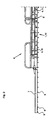
- FIG. 2 shows the rear view of the outer part 15 of the spray boom 1 with sub-segments 5 and the collision 7 in working position.
- the sub-segments 5 and the collision protection 7 are equipped with nozzles.
- the sub-segment 16 is inserted here in relation to the sub-segment 17 and belongs, inter alia, together with the sub-segment 17 and the collision protection 7 to a sub-segment group 4, which is indirectly connected via a frame, not shown, with the lifting system of the field sprayer.
Landscapes
- Life Sciences & Earth Sciences (AREA)
- Engineering & Computer Science (AREA)
- Insects & Arthropods (AREA)
- Pest Control & Pesticides (AREA)
- Wood Science & Technology (AREA)
- Zoology (AREA)
- Environmental Sciences (AREA)
- Special Spraying Apparatus (AREA)
- Catching Or Destruction (AREA)
Description
- Die Erfindung betrifft ein Spritzgestänge für Feldspritzen mit Düsenschaltung, dem mehrere Düsen zugeordnet sind, die über Schaltelemente separat schaltbar ausgebildet sind, wobei die Schaltelemente der Düsen über ein serielles Daten-BUS System aktivierbar ausgebildet sind und dass das Spritzgestänges als Schiebgestänge mit Anfahrschutz ausgebildet ist, das aus mehreren zueinander verschiebbaren Teilsegmenten besteht. Spritzgestänge, bei denen die Düsen über Schaltelemente separat schaltbar ausgebildet sind, sind bekannt. Allerdings werden die Düsen üblicherweise in Gruppen oder Teilbreiten zusammengefasst geschaltet, was neben ackerbaulichen Nachteilen auch zu einem höheren Verbrauch von Spritzmitteln führt. Insbesondere eine einfache gezielte düsenweise Schaltung der Düsen ist so nicht möglich. Aus der
EP 1 813 150 A2 ist ein Spritzgestänge für Feldspritzen bekannt, das aus einem Mittelteil und einklappbaren Seitenteilen besteht. Die einklappbaren Seitenteile bestehen jeweils aus einer Teilsegmentgruppe mit Teilsegmenten, welche zu einem Paket zusammenschiebbar sind. Dabei sind die Teilsegmente achsparallel zueinander und höhengleich verschiebbar angeordnet. Das als Paket zusammengeschobene Seitenteil kann je nach Einsatzfall verschwenkt werden. Die Schaltelemente der Düsen sind dabei über ein serielles Daten-BUS System aktivierbar. In der Praxis hat sich dieses Gerätes in Bezug auf Größen wie Flüssigkeitsmenge, Tröpfchengröße oder Ausbildung des Spritzkegels noch als verbesserungswürdig erwiesen. - Die vorliegende Erfindung hat die Aufgabe, ein Spritzgestänge für Feldspritzen zu schaffen, bei dem die Düsen auf einfache Weise individuell und gezielt sowie auch unabhängig von Teilbreiten ein- und abgeschaltet werden können.
- Diese Aufgabe wird nach einer ersten Ausführungsform der Erfindung dadurch gelöst, dass die erste Düse, die direkt benachbart zu einem verschiebbaren Teilsegment angeordnet ist, derart ausgebildet ist, dass die Ausbringmenge der Düse und der Spritzkegel während des Verschiebens des Teilsegmentes bezüglich Breite und Winkel so verändert werden, dass eine gleichmäßige Querverteilung des Spritzmittels gewährleistet ist. Damit beim Verschieben eines Teilsegmentes keine Flächen unbehandelt bleiben oder mit einer größeren Flüssigkeitsmenge behandelt werden, wird die Düse, die am äußeren Ende des Teilsegmentes angeordnet ist welches das verschiebbare Teilsegment trägt, bei der Überlappung der Spritzkegel so eingestellt, dass weitestgehend eine exakte Querverteilung gegeben ist.
- Durch diese Art der Aktivierung bzw. Schaltung der Schaltelemente der Düsen können die Düsen individuell per BUS ohne großen Aufwand an beliebiger Stelle im Spritzgestänge geschaltet werden. Jede einzelne Düse erhält dazu über einen Kommunikations-BUS eine eindeutige Adresse und kann entsprechend angesprochen werden. Die Möglichkeit, die Arbeitsbreite des Spritzgestänges stufenlos oder in Stufen zu verändern, vergrößert den Einsatzbereich einer Feldspritze erheblich, stellt aber auch besondere Herausforderungen an die Düsenschaltung. Diese Anforderungen werden durch die besondere Düsenschaltung mit dem Daten-BUS System in einfacher Weise erfüllt.
- Nach einer zweiten Ausführungsform der Erfindung ist daran gedacht, dass ein Halter mit mehreren unterschiedlichen Düsen vorgesehen ist, der direkt benachbart zu einem verschiebbaren Teilsegment angeordnet ist und dass beim Verschieben des Teilsegmentes jeweils die Düse eingeschaltet wird, die bezüglich Breite, Winkel und Ausbringmenge eine gleichmäßige Querverteilung des Spritzmittels gewährleistet.
- Diese Ausführungsform benötigt keine komplizierte einstellbare Düse wie zuvor erwähnt. Über einen Stellmotor wird zum Beispiel automatisch jeweils die Düse in Position gebracht und eingeschaltet, die für die erreichte Schiebestellung während des Verschiebens eines Teilsegmentes im Überlappungsbereich einer gleichmäßigen Querverteilung des Spritzmittels am nächsten kommt. Zur Aufrechterhaltung der gewünschten Flüssigkeitsmenge, Tröpfchengröße und Ausbildung des Spritzkegels werden dabei eine oder mehrere Düsen einer Mehrfachdüseneinheit über das BUS System aktivierbar ein- bzw. abgeschaltet
- Die Erfindung sieht weiter vor, dass die Schaltelemente elektrisch oder pneumatisch schaltbar bzw. aktivierbar ausgebildet sind. Per Daten-BUS werden die einzelnen Schaltelemente gezielt angesprochen, sie können dann per pneumatischer oder elektrischer Hilfsenergie in ihrer Schaltstellung verändert werden und so die jeweilige Düse ein- oder abschalten.
- Die Erfindung beinhaltet auch das Merkmal, dass die Feldspritze eine Steuerung aufweist, die über ein Schaltprogramm gemäß der eingespeicherten Felddaten die Düsen GPS-unterstützt ein- und abschaltet, sowohl bei Erreichen des Vorgewendes als auch im Randbereich des Feldes. Dem Stand der Technik entsprechend können die Düsen des Spritzgestänges automatisch so ein- und ausgeschaltet werden, wie es für die vorliegende Feldkontur optimal oder sinnvoll ist.
- Es ist weiterhin vorgesehen, dass die Steuerung der Feldspritze GPS-unterstützt bereits bearbeitete Feldflächen erkennt und bei Überfahren dieser Feldflächen die im Bereich dieser Feldflächen angeordneten Düsen einzeln oder in Gruppen automatisch abschaltbar ausgebildet ist. Dank dieser Ausführungsform der Steuerung der Feldspritze wird sichergestellt, dass jede Stelle des Feldes nur einmal mit Spritzmittel behandelt wird.
- Weitere Einzelheiten und Vorteile der Erfindung ergeben sich aus der nachfolgenden Beschreibung und den zugehörigen Zeichnungen, in denen der Erfindungsgegenstand skizzenhaft dargestellt ist. Es zeigen:
- Figur 1
- ein Schema der Düsenschaltung und
- Figur 2
- eine Rückansicht eines Teils eines Spritzgestänges
-
Figur 1 zeigt ein Schema der Düsenschaltung. Das Ansprechen der Schaltelemente 8 erfolgt über den Daten-BUS 20. Die Schaltelemente 8 werden hier elektrisch betätigt. Die Stromversorgung erfolgt über das Kabel 21. Die Spritzflüssigkeit bzw. das Spritzmittel 22, die sich in der Leitung 23 befindet steht unter Druck und gelangt nach Ansprechen und Schalten des jeweiligen Schaltelementes 8 zu den Düsen 6 und wird auf dem Feld versprüht. -
Figur 2 zeigt die Rückansicht des äußeren Teiles 15 des Spritzgestänges 1 mit Teilsegmenten 5 und dem Anfahrschutz 7 in Arbeitsstellung. Die Teilsegmente 5 und der Anfahrschutz 7 sind mit Düsen bestückt. Das Teilsegment 16 wird hier in Relation zum Teilsegment 17 eingeschoben und gehört unter anderem zusammen mit dem Teilsegment 17 und dem Anfahrschutz 7 zu einer Teilsegmentgruppe 4, die über einen nicht dargestellten Rahmen mittelbar mit dem Hubsystem der Feldspritze verbunden ist.
Claims (4)
- Spritzgestänge (1) für Feldspritzen mit Düsenschaltung, dem mehrere Düsen (6) zugeordnet sind, die über Schaltelemente (8) separat schaltbar ausgebildet sind, wobei die Schaltelemente (8) der Düsen (6) über ein serielles Daten-BUS System aktivierbar ausgebildet sind und das Spritzgestänge (1) als Schiebgestänge mit Anfahrschutz (7) ausgebildet ist, das aus mehreren zueinander verschiebbaren Teilsegmenten (5) besteht,
dadurch gekennzeichnet,
dass die erste Düse (13), die direkt benachbart zu einem verschiebbaren Teilsegment (5) angeordnet ist, derart ausgebildet ist, dass die Ausbringmenge der Düse (13) und der Spritzkegel während des Verschiebens des Teilsegmentes (5) bezüglich Breite und Winkel so verändert werden, dass eine gleichmäßige Querverteilung des Spritzmittels gewährleistet ist
oder
dass ein Halter mit mehreren unterschiedlichen Düsen vorgesehen ist, der direkt benachbart zu einem verschiebbaren Teilsegment (5) angeordnet ist und dass beim Verschieben des Teilsegmentes (5) jeweils die Düse eingeschaltet wird, die bezüglich Breite, Winkel und Ausbringmenge eine gleichmäßige Querverteilung des Spritzmittels gewährleistet. - Sprifizgestänge für Feldspritzen nach Anspruch 1,
dadurch gekennreichnet,
dass die Schaltelemente (8) elektrisch oder pneumatisch schaltbar bzwaktivierbar ausgebildet sind. - Sprüzgestänge für Feldspritzen nach Anspruch 1 oder 2,
dadurch gekennzeichnet,
dass die Feldspritze eine Steuerung aufweist, die über ein Schaltprogramm gemäß der eingespeicherten Felddaten die Düsen (6) GPS-unterstützt ein- und abschaltet, sowohl bei Erreichen des Vorgewendes als auch im Randbereich des Feldes. - Spritzgestänge für Feldspritzen nach Anspruch 3,
dadurch gekennzeichnet,
dass die Steuerung der Feldspritze GPS- unterstützt bereits bearbeitete Feldflächen erkennt und bei Überfahren dieser Feldflächen die im Bereich dieser Feldflächen angeordneten Düsen (6) einzeln oder in Gruppen automatisch abschaltbar ausgebildet ist
Priority Applications (1)
| Application Number | Priority Date | Filing Date | Title |
|---|---|---|---|
| PL10014331T PL2319306T3 (pl) | 2009-11-06 | 2010-11-05 | Teleskopowy zestaw belek opryskujących do opryskiwaczy polowych z układem połączeń dysz |
Applications Claiming Priority (2)
| Application Number | Priority Date | Filing Date | Title |
|---|---|---|---|
| DE102009053213A DE102009053213A1 (de) | 2009-11-06 | 2009-11-06 | Feldspritze mit Spritzgestänge |
| DE102009053212A DE102009053212A1 (de) | 2009-11-06 | 2009-11-06 | Spritzgestänge für Feldspritzen mit Düsenschaltung |
Publications (2)
| Publication Number | Publication Date |
|---|---|
| EP2319306A1 EP2319306A1 (de) | 2011-05-11 |
| EP2319306B1 true EP2319306B1 (de) | 2013-04-10 |
Family
ID=43530254
Family Applications (1)
| Application Number | Title | Priority Date | Filing Date |
|---|---|---|---|
| EP10014331.2A Active EP2319306B1 (de) | 2009-11-06 | 2010-11-05 | Teleskopisches Spritzgestänge für Feldspritzen mit Düsenschaltung |
Country Status (4)
| Country | Link |
|---|---|
| EP (1) | EP2319306B1 (de) |
| DK (1) | DK2319306T3 (de) |
| ES (1) | ES2417317T3 (de) |
| PL (1) | PL2319306T3 (de) |
Cited By (2)
| Publication number | Priority date | Publication date | Assignee | Title |
|---|---|---|---|---|
| EP2613628B1 (de) * | 2010-09-10 | 2019-07-10 | Exel Industries | Sprühvorrichtung für eine landwirtschaftsmaschine mit kartografischer steuerung |
| DE102019124182A1 (de) * | 2019-09-10 | 2021-03-11 | Amazonen-Werke H. Dreyer Gmbh & Co. Kg | Verfahren und Vorrichtung zur reihenweisen Applikation von Pflanzenschutzmitteln |
Family Cites Families (4)
| Publication number | Priority date | Publication date | Assignee | Title |
|---|---|---|---|---|
| GB2337984B (en) * | 1998-05-27 | 2003-07-02 | Matthew James Harold Rawlings | Sprayer controller and method |
| ES2171132B1 (es) * | 2000-11-16 | 2003-12-16 | Justribo Baradad Antonio | Dispositivo de regulacion de caudal de pulverizadores hidraulicos de productos fitosanitarios con control independiente en boquillas adaptado a la velocidad diferencial de desplazamiento. |
| DE102007001915A1 (de) * | 2006-01-26 | 2007-08-09 | Lemken Gmbh & Co. Kg | Spritzgestänge für Feldspritzen |
| DE102006038688A1 (de) * | 2006-08-17 | 2008-02-21 | Amazonen-Werke H. Dreyer Gmbh & Co. Kg | Spritzeinrichtung |
-
2010
- 2010-11-05 DK DK10014331.2T patent/DK2319306T3/da active
- 2010-11-05 PL PL10014331T patent/PL2319306T3/pl unknown
- 2010-11-05 ES ES10014331T patent/ES2417317T3/es active Active
- 2010-11-05 EP EP10014331.2A patent/EP2319306B1/de active Active
Cited By (3)
| Publication number | Priority date | Publication date | Assignee | Title |
|---|---|---|---|---|
| EP2613628B1 (de) * | 2010-09-10 | 2019-07-10 | Exel Industries | Sprühvorrichtung für eine landwirtschaftsmaschine mit kartografischer steuerung |
| DE102019124182A1 (de) * | 2019-09-10 | 2021-03-11 | Amazonen-Werke H. Dreyer Gmbh & Co. Kg | Verfahren und Vorrichtung zur reihenweisen Applikation von Pflanzenschutzmitteln |
| EP4027781A1 (de) * | 2019-09-10 | 2022-07-20 | Amazonen-Werke H. Dreyer SE & Co. KG | Verfahren und vorrichtung zur reihenweisen applikation von pflanzenschutzmittel |
Also Published As
| Publication number | Publication date |
|---|---|
| ES2417317T3 (es) | 2013-08-07 |
| PL2319306T3 (pl) | 2013-09-30 |
| DK2319306T3 (da) | 2013-06-03 |
| EP2319306A1 (de) | 2011-05-11 |
Similar Documents
| Publication | Publication Date | Title |
|---|---|---|
| EP2886717B1 (de) | Nachbehandlungsmaschine sowie Verfahren zum nachträglichen Bearbeiten einer frisch gefertigten Betonschicht | |
| EP2186405A1 (de) | Spritzgestänge und Verfahren zu dessen Steuerung | |
| EP3224095B1 (de) | Portalwaschanlage und verfahren zum reinigen eines kraftfahrzeuges | |
| EP4094577B1 (de) | Landwirtschaftliche feldspritze und spritzvorrichtung für eine landwirtschaftliche feldspritze sowie verfahren zur anpassung einer spritzvorrichtung für eine reihenbezogene ausbringung von spritzflüssigkeit | |
| EP2200802B1 (de) | Verfahren und vorrichtung zum steuern einer linear bewegten axe | |
| EP3372078A1 (de) | Steuersystem für einen landwirtschaftlichen sprüharm | |
| EP1813150A2 (de) | Spritzgestänge für Feldspritzen | |
| EP2567617B1 (de) | Landwirtschaftliche Feldspritze mit Mehrfachdüsenkörpern | |
| EP2319306B1 (de) | Teleskopisches Spritzgestänge für Feldspritzen mit Düsenschaltung | |
| EP2722262B1 (de) | Zentraleinheit für Rangierantrieb | |
| EP2989875B1 (de) | Gestänge eines landwirtschaftlichen gerätes | |
| DE2556707C3 (de) | Zerstäubungsgerät für Behandlungsmittel in der Landwirtschaft | |
| DE4229254C2 (de) | Spritzaggregat für eine Zweikomponentenspritzgießmaschine | |
| DE4013941A1 (de) | Anlage zum serienweisen beschichten von werkstuecken mit leitfaehigem beschichtungsmaterial | |
| EP3141668B1 (de) | Dusch-wc mit durchlauferhitzer und boiler | |
| DE4435935A1 (de) | Verfahren zum Einstellen des Walzenspaltes eines Walzwerks und Walzwerk | |
| DE102009053213A1 (de) | Feldspritze mit Spritzgestänge | |
| DE102012001185A1 (de) | Verfahren zum Betrieb eines ortsveränderbaren Arbeitsgerätes, sowie ein Arbeitsgerät zur Ausführung des Verfahrens | |
| EP3485728B1 (de) | Landwirtschaftliche verteilmaschine | |
| EP2191903B1 (de) | Verfahren zur Konstanthaltung der Markierungslinienbreite und Markierungsmaschine zur Durchführung des Verfahrens | |
| DE9203902U1 (de) | Straßenbaufahrzeug | |
| DE202009018458U1 (de) | Spritzgestänge für Feldspritzen mit Düsenschaltung | |
| EP3041679A1 (de) | Trockner zum trocknen einer materialbahn | |
| EP3544750B1 (de) | Stauchgerüst mit einer anstellzylinderschnellverstellung | |
| ヘルベルトウォルフガング | Üben nach Funakoshi |
Legal Events
| Date | Code | Title | Description |
|---|---|---|---|
| PUAI | Public reference made under article 153(3) epc to a published international application that has entered the european phase |
Free format text: ORIGINAL CODE: 0009012 |
|
| AK | Designated contracting states |
Kind code of ref document: A1 Designated state(s): AL AT BE BG CH CY CZ DE DK EE ES FI FR GB GR HR HU IE IS IT LI LT LU LV MC MK MT NL NO PL PT RO RS SE SI SK SM TR |
|
| AX | Request for extension of the european patent |
Extension state: BA ME |
|
| 17P | Request for examination filed |
Effective date: 20111111 |
|
| GRAP | Despatch of communication of intention to grant a patent |
Free format text: ORIGINAL CODE: EPIDOSNIGR1 |
|
| RIC1 | Information provided on ipc code assigned before grant |
Ipc: A01M 7/00 20060101AFI20121010BHEP |
|
| GRAS | Grant fee paid |
Free format text: ORIGINAL CODE: EPIDOSNIGR3 |
|
| GRAA | (expected) grant |
Free format text: ORIGINAL CODE: 0009210 |
|
| AK | Designated contracting states |
Kind code of ref document: B1 Designated state(s): AL AT BE BG CH CY CZ DE DK EE ES FI FR GB GR HR HU IE IS IT LI LT LU LV MC MK MT NL NO PL PT RO RS SE SI SK SM TR |
|
| REG | Reference to a national code |
Ref country code: GB Ref legal event code: FG4D Free format text: NOT ENGLISH |
|
| REG | Reference to a national code |
Ref country code: CH Ref legal event code: EP Ref country code: AT Ref legal event code: REF Ref document number: 605436 Country of ref document: AT Kind code of ref document: T Effective date: 20130415 |
|
| REG | Reference to a national code |
Ref country code: IE Ref legal event code: FG4D Free format text: LANGUAGE OF EP DOCUMENT: GERMAN |
|
| REG | Reference to a national code |
Ref country code: DK Ref legal event code: T3 |
|
| REG | Reference to a national code |
Ref country code: DE Ref legal event code: R096 Ref document number: 502010002894 Country of ref document: DE Effective date: 20130606 |
|
| REG | Reference to a national code |
Ref country code: SE Ref legal event code: TRGR |
|
| REG | Reference to a national code |
Ref country code: NL Ref legal event code: T3 |
|
| REG | Reference to a national code |
Ref country code: SK Ref legal event code: T3 Ref document number: E 14166 Country of ref document: SK |
|
| REG | Reference to a national code |
Ref country code: ES Ref legal event code: FG2A Ref document number: 2417317 Country of ref document: ES Kind code of ref document: T3 Effective date: 20130807 |
|
| REG | Reference to a national code |
Ref country code: NO Ref legal event code: T2 Effective date: 20130410 |
|
| PG25 | Lapsed in a contracting state [announced via postgrant information from national office to epo] |
Ref country code: SI Free format text: LAPSE BECAUSE OF FAILURE TO SUBMIT A TRANSLATION OF THE DESCRIPTION OR TO PAY THE FEE WITHIN THE PRESCRIBED TIME-LIMIT Effective date: 20130410 |
|
| REG | Reference to a national code |
Ref country code: LT Ref legal event code: MG4D |
|
| REG | Reference to a national code |
Ref country code: PL Ref legal event code: T3 |
|
| PG25 | Lapsed in a contracting state [announced via postgrant information from national office to epo] |
Ref country code: LT Free format text: LAPSE BECAUSE OF FAILURE TO SUBMIT A TRANSLATION OF THE DESCRIPTION OR TO PAY THE FEE WITHIN THE PRESCRIBED TIME-LIMIT Effective date: 20130410 Ref country code: GR Free format text: LAPSE BECAUSE OF FAILURE TO SUBMIT A TRANSLATION OF THE DESCRIPTION OR TO PAY THE FEE WITHIN THE PRESCRIBED TIME-LIMIT Effective date: 20130711 Ref country code: PT Free format text: LAPSE BECAUSE OF FAILURE TO SUBMIT A TRANSLATION OF THE DESCRIPTION OR TO PAY THE FEE WITHIN THE PRESCRIBED TIME-LIMIT Effective date: 20130812 Ref country code: IS Free format text: LAPSE BECAUSE OF FAILURE TO SUBMIT A TRANSLATION OF THE DESCRIPTION OR TO PAY THE FEE WITHIN THE PRESCRIBED TIME-LIMIT Effective date: 20130810 Ref country code: FI Free format text: LAPSE BECAUSE OF FAILURE TO SUBMIT A TRANSLATION OF THE DESCRIPTION OR TO PAY THE FEE WITHIN THE PRESCRIBED TIME-LIMIT Effective date: 20130410 |
|
| PG25 | Lapsed in a contracting state [announced via postgrant information from national office to epo] |
Ref country code: BG Free format text: LAPSE BECAUSE OF FAILURE TO SUBMIT A TRANSLATION OF THE DESCRIPTION OR TO PAY THE FEE WITHIN THE PRESCRIBED TIME-LIMIT Effective date: 20130710 Ref country code: HR Free format text: LAPSE BECAUSE OF FAILURE TO SUBMIT A TRANSLATION OF THE DESCRIPTION OR TO PAY THE FEE WITHIN THE PRESCRIBED TIME-LIMIT Effective date: 20130410 Ref country code: CY Free format text: LAPSE BECAUSE OF FAILURE TO SUBMIT A TRANSLATION OF THE DESCRIPTION OR TO PAY THE FEE WITHIN THE PRESCRIBED TIME-LIMIT Effective date: 20130410 Ref country code: RS Free format text: LAPSE BECAUSE OF FAILURE TO SUBMIT A TRANSLATION OF THE DESCRIPTION OR TO PAY THE FEE WITHIN THE PRESCRIBED TIME-LIMIT Effective date: 20130410 Ref country code: LV Free format text: LAPSE BECAUSE OF FAILURE TO SUBMIT A TRANSLATION OF THE DESCRIPTION OR TO PAY THE FEE WITHIN THE PRESCRIBED TIME-LIMIT Effective date: 20130410 |
|
| PG25 | Lapsed in a contracting state [announced via postgrant information from national office to epo] |
Ref country code: EE Free format text: LAPSE BECAUSE OF FAILURE TO SUBMIT A TRANSLATION OF THE DESCRIPTION OR TO PAY THE FEE WITHIN THE PRESCRIBED TIME-LIMIT Effective date: 20130410 |
|
| PLBE | No opposition filed within time limit |
Free format text: ORIGINAL CODE: 0009261 |
|
| STAA | Information on the status of an ep patent application or granted ep patent |
Free format text: STATUS: NO OPPOSITION FILED WITHIN TIME LIMIT |
|
| PG25 | Lapsed in a contracting state [announced via postgrant information from national office to epo] |
Ref country code: RO Free format text: LAPSE BECAUSE OF FAILURE TO SUBMIT A TRANSLATION OF THE DESCRIPTION OR TO PAY THE FEE WITHIN THE PRESCRIBED TIME-LIMIT Effective date: 20130410 |
|
| 26N | No opposition filed |
Effective date: 20140113 |
|
| REG | Reference to a national code |
Ref country code: HU Ref legal event code: AG4A Ref document number: E018591 Country of ref document: HU |
|
| REG | Reference to a national code |
Ref country code: DE Ref legal event code: R097 Ref document number: 502010002894 Country of ref document: DE Effective date: 20140113 |
|
| PG25 | Lapsed in a contracting state [announced via postgrant information from national office to epo] |
Ref country code: MC Free format text: LAPSE BECAUSE OF FAILURE TO SUBMIT A TRANSLATION OF THE DESCRIPTION OR TO PAY THE FEE WITHIN THE PRESCRIBED TIME-LIMIT Effective date: 20130410 |
|
| REG | Reference to a national code |
Ref country code: IE Ref legal event code: MM4A |
|
| PG25 | Lapsed in a contracting state [announced via postgrant information from national office to epo] |
Ref country code: IE Free format text: LAPSE BECAUSE OF NON-PAYMENT OF DUE FEES Effective date: 20131105 |
|
| PG25 | Lapsed in a contracting state [announced via postgrant information from national office to epo] |
Ref country code: SM Free format text: LAPSE BECAUSE OF FAILURE TO SUBMIT A TRANSLATION OF THE DESCRIPTION OR TO PAY THE FEE WITHIN THE PRESCRIBED TIME-LIMIT Effective date: 20130410 |
|
| PG25 | Lapsed in a contracting state [announced via postgrant information from national office to epo] |
Ref country code: TR Free format text: LAPSE BECAUSE OF FAILURE TO SUBMIT A TRANSLATION OF THE DESCRIPTION OR TO PAY THE FEE WITHIN THE PRESCRIBED TIME-LIMIT Effective date: 20130410 |
|
| REG | Reference to a national code |
Ref country code: CH Ref legal event code: PL |
|
| PG25 | Lapsed in a contracting state [announced via postgrant information from national office to epo] |
Ref country code: CH Free format text: LAPSE BECAUSE OF NON-PAYMENT OF DUE FEES Effective date: 20141130 Ref country code: LU Free format text: LAPSE BECAUSE OF NON-PAYMENT OF DUE FEES Effective date: 20131105 Ref country code: LI Free format text: LAPSE BECAUSE OF NON-PAYMENT OF DUE FEES Effective date: 20141130 Ref country code: MK Free format text: LAPSE BECAUSE OF FAILURE TO SUBMIT A TRANSLATION OF THE DESCRIPTION OR TO PAY THE FEE WITHIN THE PRESCRIBED TIME-LIMIT Effective date: 20130410 |
|
| PG25 | Lapsed in a contracting state [announced via postgrant information from national office to epo] |
Ref country code: MT Free format text: LAPSE BECAUSE OF FAILURE TO SUBMIT A TRANSLATION OF THE DESCRIPTION OR TO PAY THE FEE WITHIN THE PRESCRIBED TIME-LIMIT Effective date: 20130410 |
|
| REG | Reference to a national code |
Ref country code: FR Ref legal event code: PLFP Year of fee payment: 6 |
|
| REG | Reference to a national code |
Ref country code: FR Ref legal event code: PLFP Year of fee payment: 7 |
|
| REG | Reference to a national code |
Ref country code: FR Ref legal event code: PLFP Year of fee payment: 8 |
|
| PG25 | Lapsed in a contracting state [announced via postgrant information from national office to epo] |
Ref country code: AL Free format text: LAPSE BECAUSE OF FAILURE TO SUBMIT A TRANSLATION OF THE DESCRIPTION OR TO PAY THE FEE WITHIN THE PRESCRIBED TIME-LIMIT Effective date: 20130410 |
|
| PGFP | Annual fee paid to national office [announced via postgrant information from national office to epo] |
Ref country code: NL Payment date: 20181213 Year of fee payment: 15 Ref country code: PL Payment date: 20181024 Year of fee payment: 9 Ref country code: AT Payment date: 20181127 Year of fee payment: 9 Ref country code: CZ Payment date: 20181101 Year of fee payment: 9 Ref country code: SK Payment date: 20181102 Year of fee payment: 9 Ref country code: HU Payment date: 20181121 Year of fee payment: 9 Ref country code: DK Payment date: 20181126 Year of fee payment: 9 Ref country code: NO Payment date: 20181123 Year of fee payment: 9 |
|
| PGFP | Annual fee paid to national office [announced via postgrant information from national office to epo] |
Ref country code: GB Payment date: 20181130 Year of fee payment: 9 Ref country code: ES Payment date: 20181218 Year of fee payment: 9 Ref country code: BE Payment date: 20181121 Year of fee payment: 9 |
|
| REG | Reference to a national code |
Ref country code: DE Ref legal event code: R082 Ref document number: 502010002894 Country of ref document: DE |
|
| REG | Reference to a national code |
Ref country code: DK Ref legal event code: EBP Effective date: 20191130 Ref country code: NO Ref legal event code: MMEP |
|
| REG | Reference to a national code |
Ref country code: SE Ref legal event code: EUG |
|
| PG25 | Lapsed in a contracting state [announced via postgrant information from national office to epo] |
Ref country code: NO Free format text: LAPSE BECAUSE OF NON-PAYMENT OF DUE FEES Effective date: 20191130 Ref country code: CZ Free format text: LAPSE BECAUSE OF NON-PAYMENT OF DUE FEES Effective date: 20191105 |
|
| REG | Reference to a national code |
Ref country code: SK Ref legal event code: MM4A Ref document number: E 14166 Country of ref document: SK Effective date: 20191105 |
|
| REG | Reference to a national code |
Ref country code: AT Ref legal event code: MM01 Ref document number: 605436 Country of ref document: AT Kind code of ref document: T Effective date: 20191105 |
|
| REG | Reference to a national code |
Ref country code: BE Ref legal event code: MM Effective date: 20191130 |
|
| PG25 | Lapsed in a contracting state [announced via postgrant information from national office to epo] |
Ref country code: SE Free format text: LAPSE BECAUSE OF NON-PAYMENT OF DUE FEES Effective date: 20191106 Ref country code: HU Free format text: LAPSE BECAUSE OF NON-PAYMENT OF DUE FEES Effective date: 20191106 Ref country code: SK Free format text: LAPSE BECAUSE OF NON-PAYMENT OF DUE FEES Effective date: 20191105 |
|
| GBPC | Gb: european patent ceased through non-payment of renewal fee |
Effective date: 20191105 |
|
| PG25 | Lapsed in a contracting state [announced via postgrant information from national office to epo] |
Ref country code: DK Free format text: LAPSE BECAUSE OF NON-PAYMENT OF DUE FEES Effective date: 20191130 Ref country code: IT Free format text: LAPSE BECAUSE OF NON-PAYMENT OF DUE FEES Effective date: 20191105 Ref country code: GB Free format text: LAPSE BECAUSE OF NON-PAYMENT OF DUE FEES Effective date: 20191105 |
|
| PG25 | Lapsed in a contracting state [announced via postgrant information from national office to epo] |
Ref country code: AT Free format text: LAPSE BECAUSE OF NON-PAYMENT OF DUE FEES Effective date: 20191105 Ref country code: BE Free format text: LAPSE BECAUSE OF NON-PAYMENT OF DUE FEES Effective date: 20191130 |
|
| REG | Reference to a national code |
Ref country code: ES Ref legal event code: FD2A Effective date: 20210527 |
|
| PG25 | Lapsed in a contracting state [announced via postgrant information from national office to epo] |
Ref country code: ES Free format text: LAPSE BECAUSE OF NON-PAYMENT OF DUE FEES Effective date: 20191106 |
|
| PG25 | Lapsed in a contracting state [announced via postgrant information from national office to epo] |
Ref country code: PL Free format text: LAPSE BECAUSE OF NON-PAYMENT OF DUE FEES Effective date: 20191105 |
|
| P01 | Opt-out of the competence of the unified patent court (upc) registered |
Effective date: 20230518 |
|
| PGFP | Annual fee paid to national office [announced via postgrant information from national office to epo] |
Ref country code: FR Payment date: 20231123 Year of fee payment: 14 |
|
| REG | Reference to a national code |
Ref country code: DE Ref legal event code: R084 Ref document number: 502010002894 Country of ref document: DE |
|
| REG | Reference to a national code |
Ref country code: NL Ref legal event code: MM Effective date: 20241201 |
|
| PG25 | Lapsed in a contracting state [announced via postgrant information from national office to epo] |
Ref country code: NL Free format text: LAPSE BECAUSE OF NON-PAYMENT OF DUE FEES Effective date: 20241201 |
|
| PG25 | Lapsed in a contracting state [announced via postgrant information from national office to epo] |
Ref country code: FR Free format text: LAPSE BECAUSE OF NON-PAYMENT OF DUE FEES Effective date: 20241130 |
|
| PGFP | Annual fee paid to national office [announced via postgrant information from national office to epo] |
Ref country code: DE Payment date: 20251106 Year of fee payment: 16 |