EP2319231B1 - Portable communication device having a dual sliding flip hinge assembly - Google Patents
Portable communication device having a dual sliding flip hinge assembly Download PDFInfo
- Publication number
- EP2319231B1 EP2319231B1 EP09789466.1A EP09789466A EP2319231B1 EP 2319231 B1 EP2319231 B1 EP 2319231B1 EP 09789466 A EP09789466 A EP 09789466A EP 2319231 B1 EP2319231 B1 EP 2319231B1
- Authority
- EP
- European Patent Office
- Prior art keywords
- assembly
- hinge
- hinge plate
- portable communication
- communication device
- Prior art date
- Legal status (The legal status is an assumption and is not a legal conclusion. Google has not performed a legal analysis and makes no representation as to the accuracy of the status listed.)
- Not-in-force
Links
Images


Classifications
-
- H—ELECTRICITY
- H04—ELECTRIC COMMUNICATION TECHNIQUE
- H04M—TELEPHONIC COMMUNICATION
- H04M1/00—Substation equipment, e.g. for use by subscribers
- H04M1/02—Constructional features of telephone sets
- H04M1/0202—Portable telephone sets, e.g. cordless phones, mobile phones or bar type handsets
- H04M1/0206—Portable telephones comprising a plurality of mechanically joined movable body parts, e.g. hinged housings
- H04M1/0247—Portable telephones comprising a plurality of mechanically joined movable body parts, e.g. hinged housings comprising more than two body parts
-
- H—ELECTRICITY
- H04—ELECTRIC COMMUNICATION TECHNIQUE
- H04M—TELEPHONIC COMMUNICATION
- H04M1/00—Substation equipment, e.g. for use by subscribers
- H04M1/02—Constructional features of telephone sets
- H04M1/0202—Portable telephone sets, e.g. cordless phones, mobile phones or bar type handsets
- H04M1/0206—Portable telephones comprising a plurality of mechanically joined movable body parts, e.g. hinged housings
- H04M1/0208—Portable telephones comprising a plurality of mechanically joined movable body parts, e.g. hinged housings characterized by the relative motions of the body parts
- H04M1/0214—Foldable telephones, i.e. with body parts pivoting to an open position around an axis parallel to the plane they define in closed position
-
- H—ELECTRICITY
- H04—ELECTRIC COMMUNICATION TECHNIQUE
- H04M—TELEPHONIC COMMUNICATION
- H04M1/00—Substation equipment, e.g. for use by subscribers
- H04M1/02—Constructional features of telephone sets
- H04M1/0202—Portable telephone sets, e.g. cordless phones, mobile phones or bar type handsets
- H04M1/0206—Portable telephones comprising a plurality of mechanically joined movable body parts, e.g. hinged housings
- H04M1/0208—Portable telephones comprising a plurality of mechanically joined movable body parts, e.g. hinged housings characterized by the relative motions of the body parts
- H04M1/0235—Slidable or telescopic telephones, i.e. with a relative translation movement of the body parts; Telephones using a combination of translation and other relative motions of the body parts
- H04M1/0239—Sliding mechanism with two degree of freedom, e.g. translation in two different directions
-
- H—ELECTRICITY
- H04—ELECTRIC COMMUNICATION TECHNIQUE
- H04M—TELEPHONIC COMMUNICATION
- H04M2250/00—Details of telephonic subscriber devices
- H04M2250/16—Details of telephonic subscriber devices including more than one display unit
-
- H—ELECTRICITY
- H04—ELECTRIC COMMUNICATION TECHNIQUE
- H04M—TELEPHONIC COMMUNICATION
- H04M2250/00—Details of telephonic subscriber devices
- H04M2250/22—Details of telephonic subscriber devices including a touch pad, a touch sensor or a touch detector
Definitions
- the present invention relates generally to portable communication devices, and more particularly, to a portable communication device having a dual sliding flip hinge assembly.
- Portable communication devices and in particular mobile telephones, are used for a wide variety of applications.
- mobile phones are used not only for phone conversations and for sending/receiving messages, but also for browsing the internet, viewing multimedia content, such as movies or music, and for playing games, etc.
- the display screen on a mobile phone is limited by the size of the phone.
- the surface area available for the display screen, functional keys and a keypad is reduced.
- some mobile devices are designed with a base and a display that is movable relative to the base.
- the keypad often is incorporated into the base and exposed only after opening/moving the display.
- clamshell devices in which the display is connected to the base via a conventional rotational hinge
- slider devices in which the display is slidable with respect to the base, for example, on a rail or a track.
- US 2006/0135222 discloses a portable apparatus having a display device adapted to be watched in the horizontal position and retained with a slant for convenient key operation using both hands.
- the portable apparatus includes a first housing; a second housing adapted to fold on and unfold from the first housing; a hinge device adapted to connect the first and second housings about a first hinge axis; a third housing positioned between the first and second housings and adapted to rotate from the first housing about a second hinge axis, which is spaced from and perpendicular to the first hinge axis, in a direction moving away from the hinge device to be placed parallel to the longitudinal direction of the first and second housings; and a swing hinge device positioned on the first housing to connect the first and third housings in such a manner that they can rotate about the second hinge axis.
- US 2006/105824 discloses a sliding-folding type portable communication apparatus that provides advantages of both sliding type and folding type portable communication apparatuses.
- the sliding-folding type portable communication apparatus has a soft cover having a folding section, a hinge unit provided in the folding section, and a body coupled to the soft cover while facing one surface of the soft cover, the body sliding lengthwise along the soft cover and being opened/closed when the soft cover is extended/folded.
- a portable communication device is provided with a dual sliding hinge assembly.
- the dual sliding hinge assembly is configured to couple an intermediate assembly to a base assembly and a flip assembly such that the intermediate portion can slide relative to the base assembly and the flip assembly along a first direction and along a second direction perpendicular to the first direction.
- the dual sliding hinge assembly also is configured to facilitate rotation of the intermediate assembly when the intermediate assembly is slid along the second direction.
- the base assembly, intermediate assembly and/or flip assembly may be configured to include touch-input devices and/or display devices.
- a portable communication device that includes a base assembly; a flip assembly coupled to the base assembly such that the flip assembly is rotatable relative to the base assembly; and an intermediate assembly operatively coupled to the base assembly and the flip assembly by a dual sliding hinge assembly, wherein the dual sliding hinge assembly is configured to facilitate sliding movement between the intermediate assembly and the base assembly along a first direction and along a second direction perpendicular to the first direction.
- the dual sliding hinge assembly is configured to facilitate rotational movement between the intermediate assembly and the base assembly.
- the dual sliding hinge assembly is configured to facilitate rotational movement between the intermediate assembly and the base assembly when the intermediate assembly is slid along the second direction.
- the dual sliding hinge assembly includes a first hinge plate coupled to a second hinge plate and configured for sliding movement between the second hinge plate and the first hinge plate along the first direction.
- the dual sliding hinge assembly includes a third hinge plate coupled to the second hinge plate and configured for sliding motion between the third hinge plate and the second hinge plate along a second direction perpendicular to the first direction.
- the dual sliding hinge assembly includes a fourth hinge plate coupled to the third hinge plate and configured for rotational movement between the fourth hinge plate and the third hinge plate.
- the fourth hinge plate is coupled to the third hinge plate by a spring hinge.
- the fourth hinge plate is rotatable to an angle of up to about 90 degrees.
- the intermediate assembly includes at least one display.
- the intermediate assembly includes a touch-input device that is revealed when a portion of the intermediate assembly is slid along the second direction.
- the base assembly and the flip assembly each comprise a touch-sensitive input device.
- each touch-sensitive input device is a touch-sensitive display.
- the portable communication device is a mobile telephone.
- a portable communication device that includes a base assembly; a flip assembly; and an intermediate assembly; wherein the base assembly, the intermediate assembly and the top assembly are operatively coupled by a dual hinge assembly, wherein the dual hinge assembly is configured to facilitate rotational movement between the base assembly and the flip assembly, sliding movement between the base assembly and the intermediate assembly along a first direction and along a second direction perpendicular to the first direction, and rotational movement of the intermediate assembly relative to the base assembly when the intermediate assembly is slid along the second direction.
- a dual sliding hinge assembly for use in connection with a portable communication device, where the dual sliding hinge assembly includes a first hinge plate coupled to a second hinge plate and configured for sliding movement between the second hinge plate and the first hinge plate along a first direction; a third hinge plate coupled to the second hinge plate and configured for sliding motion between the third hinge plate and the second hinge plate along a second direction perpendicular to the first direction; and a fourth hinge plate coupled to the third hinge plate and configured for rotational movement between the fourth hinge plate and the third hinge plate.
- the dual sliding hinge assembly is configured to facilitate rotation of the fourth hinge plate of about 90 degrees relative to the third hinge plate.
- a portable communication device that includes a first assembly; and a second assembly coupled to the first assembly by a dual sliding hinge assembly; wherein the dual sliding hinge assembly is configured to facilitate sliding movement between the base assembly and the intermediate assembly along a first direction and along a second direction perpendicular to the first direction, and rotational movement of the intermediate assembly relative to the base assembly when the intermediate assembly is slid along the second direction
- the term “portable communication device” includes portable radio communication equipment.
- portable radio communication equipment which herein after is referred to as a mobile phone, a mobile device, a mobile radio terminal or a mobile terminal, includes all electronic equipment, including, but not limited to, mobile telephones, pagers, communicators, i.e., electronic organizers, smartphones, personal digital assistants (PDAs), or the like.
- the portable communication device is primarily referred to as a mobile telephone or a mobile phone.
- the description and illustrations of the mobile telephone are intended to serve as a non-limiting exemplary environment for the inventive concepts described herein, and it will be appreciated that the invention is not intended to be limited to a mobile telephone, but rather can be any type of electronic equipment.
- Mobile phones with slider hinges typically include a keypad on the base that is exposed by sliding the display relative to the base.
- Functional keys typically located on the same surface as the display, are used for navigating menus and for initiating various functions on the device. Due to the location of the functional keys, the surface area available for the display screen is reduced, thus requiring the display screen to also be reduced in size. Furthermore, when the display is slid open, the functional keys are slid away from the user's hands, making them generally difficult to reach and/or inconvenient to use.
- the present disclosure recognizes shortcomings with conventional portable communication devices, including slider mobile phones and clamshell phones, as well as larger phones., and provides a portable communication device (e.g., a mobile phone) having a dual sliding hinge assembly.
- the dual sliding hinge assembly may be configured to slidingly couple an intermediate assembly to a base assembly and a flip assembly such that the intermediate assembly may be slid along a first direction and along a second direction perpendicular to the first direction.
- the dual sliding hinge assembly is configured to facilitate rotation of the intermediate assembly after the intermediate assembly is slid along the second direction.
- the provision of a dual sliding flip hinge assembly allows for a mobile phone that has the look and feel of a larger phone with more display area and/or control area and greater versatility and configurability with the smaller footprint often associated with slider and/or clamshell phones.
- the mobile phone 10 includes a dual sliding hinge assembly 12 (also referred to as a dual hinge assembly or simply as a hinge assembly).
- the dual sliding hinge assembly is configured to couple a base assembly 14 and a flip assembly 16 to an intermediate assembly 18 such that the intermediate assembly is slidable relative to the base assembly 14 and the flip assembly 16 along a first direction, a along a second direction perpendicular to the first direction and rotatable when slid along the second direction.
- FIG. 1 shows a top portion of the flip assembly 16 that would be exposed when the mobile phone is in a closed configuration.
- the top portion 20 of the flip assembly 16 includes an outer display 22, for example, a display that may be viewed when the phone is in a closed position and/or in a standby mode.
- the top portion 20 of the flip assembly 16 may include or otherwise define a touch-sensitive input area 24 (e.g., a touch-input display or other touch-input control area).
- the touch-sensitive area 24 is configured to provide functional and/or navigational keys 26.
- the top portion of the first assembly may be equipped without an outer display and/or without a touch-sensitive input area without departing from the scope of the present invention.
- the functional and/or navigational keys 26 may provide for a variety of user input operations.
- the functional keys 26 typically include special function keys, such as a "call send” key for initiating or answering a call, and a "call end” key for ending or “hanging up” a call.
- Special function keys also may include menu navigation keys, for example, for navigating through a menu displayed on the display(s) to select different telephone functions, profiles, settings, etc., as is conventional.
- Other navigational keys or controls may include directional keys (e.g., up, down, left, and right) to highlight different links, or icons, or to navigate text or other documents, etc.
- the navigational controls 24 also may be in the form of a roller ball or navigational ball, as will be appreciated.
- Other keys associated with the mobile telephone may include a volume key, an audio mute key, an on/off power key, a web browser launch key, a camera key and the like.
- the navigational keys may be embodied as "hard keys” or “soft keys” implemented on a touch-sensitive input device.
- the outer display 22 (e.g., a touch screen) is configured to display information to a user, such as, operating state, time, telephone numbers, contact information, menus, etc.
- the user also can view and utilize various features and functions related to the various operating states of the mobile phone 10 on the display 22.
- the display 22 also may be used to visually display content received by the mobile telephone 10 and/or retrieved from a memory of the mobile telephone 10. For example, the user can watch movies, play video games, and browse the internet, etc., on the screen.
- Such audio/video materials may be stored on memory within the phone or accessed from remote servers, as will be appreciated.
- the mobile phone 10 includes a base assembly 14 and a flip assembly 16 that are rotationally coupled together (e.g., by a spring hinge or by a portion of the dual sliding hinge assembly 12), such that the flip assembly 16 may be rotated relative to the base assembly 14 (e.g., such that the flip assembly may be opened or closed).
- the base assembly 14 and the flip assembly 16 are operatively coupled to the intermediate assembly 18 by the dual sliding hinge assembly 12 such that the intermediate assembly 18 may be slid or otherwise laterally translated relative to the base assembly 14 and the flip assembly 16 when the flip assembly is rotated to a completely open position (e.g., a position where the flip assembly is at an angle of about 180 degrees relative to the base assembly).
- the dual sliding hinge assembly 12 is configured such that the intermediate assembly 18 may be slid or otherwise translated along a first direction as well as being slid or otherwise laterally translated along a second direction in a direction perpendicular to the first direction.
- the dual sliding hinge assembly facilitates sliding of the intermediate assembly from a position substantially over the flip assembly 16 to a position partially over the flip assembly and partially over the base assembly.
- the dual sliding hinge assembly facilitates sliding or lateral motion of the intermediate assembly along the second direction.
- the mobile phone is configured such that the intermediate assembly includes or otherwise houses an auxiliary assembly 30 (e.g., a dedicated keypad or a touch-sensitive input device, such as a dynamic keypad).
- the dual sliding hinge assembly 12 is configured to facilitate rotation of the intermediate assembly 18 (or at least a portion of the intermediate assembly) once the intermediate assembly has been slid or otherwise laterally translated along the second direction.
- the intermediate assembly may be rotated with sliding of the intermediate assembly along the second direction.
- the intermediate assembly may then by rotated into a relatively upright position (e.g., rotated about an angle of up to about 90 degrees relative to the plane of the base assembly and the flip assembly when the base assembly and the flip assembly are in a fully open position).
- the auxiliary area 30 may also be revealed and/or utilized by a user of the phone. As can be seen in FIG.
- the provision of a dual sliding hinge assembly that also facilitates rotation of the intermediate assembly allows the phone to be configured into a laptop-like configuration, which a user may find useful for a variety of applications, such as web browsing, text entry, messaging, gaming and the like.
- the flip assembly includes a first touch-sensitive input device 32 (e.g., a touch-sensitive display or touch screen).
- the base assembly may be configured to include another touch-sensitive input device 34 (e.g., a touch-sensitive display or touch screen).
- the intermediate assembly 18 may also include or otherwise house a touch-sensitive display or touch screen 36. Alternatively, the intermediate assembly 18 may simply include a conventional display.
- touch-sensitive input devices 32, 34 and 36 each are touch-sensitive displays or touch screens.
- Exemplary touch screens include thin film transistor (TFT) LCD screens. It will be appreciated that different screens, such as larger or smaller screens, or other thin screen technology may be utilized without departing from the scope of the present invention.
- TFT thin film transistor
- the screens may be navigated by using a stylus or by otherwise touching the surface of the screen to select various functions and/or to input information or data into the phone.
- keys or key-like functionality also may be embodied as a touch screen on the display screen, and it will be appreciated that in such embodiments, the functional and/or navigational keys may be incorporated into the touch screen to incorporate a larger screen on the display.
- the base assembly 14 also houses a battery 50 operatively coupled to a main printed circuit board assembly (PCBA), which includes the electronics, memory, and circuitry, etc., necessary for operating the mobile phone 10, including conventional call circuitry that enables the mobile telephone 10 to establish a call or otherwise exchange signals other devices, such as other mobile devices, internet web servers, media servers, or the like.
- the call circuitry also may be responsible for transmitting and receiving text messages, emails, or text documents.
- the mobile phone 10 may include circuitry for browsing the internet, playing or viewing audio/visual materials, such as picture, music or video files and for gaming operations. Circuitry that controls the touch-sensitive input devices 32, 34 and 36 also is included.
- the display control circuitry dynamically adapts the displayed output of the touch-sensitive input devices 32, 34 and 36 depending upon the mode in which the phone is operating.
- the mobile phone 10 can be configured to operate in both portrait and landscape orientations depending upon the relative positions of the flip assembly 16 and the intermediate assembly 16.
- the main PCBA is housed within the base assembly 14 and electrically connected to the battery 50, which provides the necessary power for operating the mobile phone 10.
- a connector establishes an electrical connection between the battery 50 and the adjacent PCBA.
- the PCBA may be connected to the various touch-sensitive input devices and/or displays with suitable flex circuitry.
- the PCBA may be connected to auxiliary PCBAs associated with the flip and intermediate assemblies by suitable flex circuitry.
- the dual sliding hinge assembly 12 includes a first hinge plate 40, a second hinge plate 42, a third hinge plate 44, and a fourth hinge plate 46. Further, as is described more fully below, the dual sliding hinge assembly also includes a flip hinge portion 48, for example, rotationally coupling the third hinge plate 44 to the fourth hinge plate 46.
- the dual sliding hinge assembly 12 may also include an additional flip hinge portion (e.g., a spring hinge) that is operative to rotationally couple the flip assembly to the base assembly.
- the base assembly and the flip assembly may be rotationally coupled by a separate hinge mechanism (e.g., a spring hinge).
- a separate hinge mechanism e.g., a spring hinge
- the exemplary hinge plates 40, 42, 44 and 46 may include any suitable sliding hinge plates or sliding hinge components, such as cooperative rail assemblies or the like.
- the various hinge plates illustrated in FIGS. 7-12 are not intended to be limited to a particular geometry (e.g., not intended to be limited to a plate-type geometry).
- the dual sliding hinge assembly (and the various portions of the hinge assembly) may be made of any suitable material, including, but not limited to, steel or another metal or plastic.
- the first hinge plate may be formed integrally with the base assembly or the flip assembly and the fourth hinge plate may be formed integrally with the intermediate assembly.
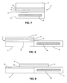
- FIG. 7 shows the dual sliding hinge assembly 12 with the mobile phone in a closed configuration
- FIGS. 8-12 show the dual sliding hinge assembly 12 with the mobile phone in an open configuration.
- the intermediate assembly may be moved relative to the base assembly and the flip assembly along a first direction as shown in figure 9 .
- the sliding motion along the first direction may be facilitated by the cooperative sliding relationship between the first hinge plates 40 and the second hinge plate 42.
- first and second hinge plates cooperate to facilitate sliding motion of the intermediate assembly from a position completely over the flip assembly to a position partially over the flip assembly and partially over the base assembly (e.g., in a position relatively centered over the flip assembly and the base assembly).
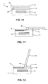
- FIGS. 10-12 show exemplary end views of the mobile phone and the associated dual sliding hinge assembly 12.
- the dual sliding hinge assembly may facilitate further sliding motion along a direction perpendicular to the first direction (as shown in FIG. 11 ).
- the second hinge plate 42 and the third hinge plate 44 cooperate to facilitate sliding of the intermediate assembly along the second direction.
- sliding of the intermediate assembly along the second direction may reveal an auxiliary area 30 such as a keypad, a display or a touch-sensitive input device, then it is housed on top of, adjacent to, or with in the second hinge plate such that the auxiliary assembly 30 is revealed once the intermediate assembly is slid along the second direction.
- an auxiliary area 30 such as a keypad, a display or a touch-sensitive input device
- the fourth hinge plate may be rotated relative to the third hinge plate by way of a rotational hinge element 48 that rotationally couples the third hinge plate 44 to the fourth hinge plate 46. It will be appreciated that it is not required for the intermediate assembly to be slid along the second direction before the intermediate assembly is rotated in a relatively upright position relative to the flip assembly and the base assembly. As shown in FIG. 12 , when the intermediate assembly is slid along the second direction and further rotated into a relatively upright position, the user of the user of the mobile phone may be able to enter data via the auxiliary device 30 while viewing a relatively upright display coupled to be fourth hinge plate in a laptop-like configuration.
- the various components of the dual sliding hinge assembly may be incorporated within the housings of the base assembly, the flip assembly and/or the intermediate assembly such that the dual sliding hinge assembly is not readily viewable by a user of the phone.
- the various components of the dual sliding hinge assembly may be integrated into suitable cosmetic plastics.
- the various hinge plates of the dual sliding hinge assembly may include a spring or other resilient member that requires an initial force before allowing relative movement between the various cooperative hinge plates.
- the phone may include three distinct displays 32, 34 and 36 on the "inside" of the mobile phone, each with a touch-sensitive input portion so that they may be used or otherwise configured as input devices.
- the mobile phone may be configured to include an auxiliary display or input area 30 that is exposed when the intermediate assembly is slid along the second direction, optionally, with the display 36 rotated in a relatively upright position.
- display 36 within the intermediate assembly may be configured to function as a typical keypad (e.g., alphanumeric keypad and/or QWERTY keypad), and display 36 within the base is hidden.
- the mobile phone When the mobile phone is transitioned to a web/multimedia mode (e.g., by opening the flip assembly and sliding the intermediate assembly relative to the base) all three touch-sensitive input surfaces 32, 34 and 36 are exposed (as well as possibly auxiliary area 30), and display 36 may switch to function as the main display, while displays 32 and 34 are configured to operate as input devices.
- the transition of display 36 from keypad mode to main display mode may be triggered by an electromechanical switch is activated upon sliding movement of the intermediate assembly into a relatively centralized position.
- the user may hold the mobile device in both hands in a landscape mode as the user navigates/operates the device with his/her thumbs.
- other use cases and configurations may be realized without departing from the scope of the present invention.
- a mobile phone having a base assembly, and intermediate assembly and a flip assembly coupled by a dual sliding hinge assembly provides a mobile phone having enhanced functionality and versatility.
- the provision of a dual sliding hinge assembly provides the conveniently sized form factor or footprint on the phone along with the enhanced control space/features and/or display space/features found in phones having larger form factors.
- the above-describe mobile phone provides the look and feel of a larger phone with more display area and/or control area with a smaller footprint often associated with clamshell and/or slider phones.
- the phone may be configured to have the look and feel of a mini laptop computer.
- a dual sliding hinge assembly that couples a base assembly, intermediate assembly and flip assembly (with the base assembly, intermediate assembly and flip assembly having touch-input devices) provides for a versatile mobile phone that may be operated in a first mode (e.g., in a portrait orientation) for calling and simple messaging operations, and a second mode (e.g., in a landscape orientation) for web surfing, gaming and/or other multimedia operations.
- a first mode e.g., in a portrait orientation
- second mode e.g., in a landscape orientation
- the flip assembly may be opened and the intermediate assembly may be slid to reveal touch-sensitive input device (and possibly triggering a transition to a multimedia mode), whereby touch-sensitive device 36 functions as the main display and touch-sensitive devices 32 and 34 (as well as any touch-sensitive input device within the auxiliary area 30) are configured as touch-sensitive control interfaces.
- touch-sensitive device 36 functions as the main display
- touch-sensitive devices 32 and 34 are configured as touch-sensitive control interfaces.
- the phone can operate in a "balanced mode" where a user can hold the device with both hands in a landscape mode having control areas on both sides of a relatively-centered main display.
- Other modes of operation may be realized without departing from the scope of the present invention.
Description
- The present invention relates generally to portable communication devices, and more particularly, to a portable communication device having a dual sliding flip hinge assembly.
- Portable communication devices, and in particular mobile telephones, are used for a wide variety of applications. For example, mobile phones are used not only for phone conversations and for sending/receiving messages, but also for browsing the internet, viewing multimedia content, such as movies or music, and for playing games, etc.
- In general, the display screen on a mobile phone is limited by the size of the phone. As mobile phones are reduced in size, the surface area available for the display screen, functional keys and a keypad is reduced. In order to maximize the size of the display screen, some mobile devices are designed with a base and a display that is movable relative to the base. In these mobile phones, the keypad often is incorporated into the base and exposed only after opening/moving the display. Known mobile devices of this variety include clamshell devices, in which the display is connected to the base via a conventional rotational hinge, and slider devices, in which the display is slidable with respect to the base, for example, on a rail or a track.
-
US 2006/0135222 discloses a portable apparatus having a display device adapted to be watched in the horizontal position and retained with a slant for convenient key operation using both hands. The portable apparatus includes a first housing; a second housing adapted to fold on and unfold from the first housing; a hinge device adapted to connect the first and second housings about a first hinge axis; a third housing positioned between the first and second housings and adapted to rotate from the first housing about a second hinge axis, which is spaced from and perpendicular to the first hinge axis, in a direction moving away from the hinge device to be placed parallel to the longitudinal direction of the first and second housings; and a swing hinge device positioned on the first housing to connect the first and third housings in such a manner that they can rotate about the second hinge axis. -
US 2006/105824 discloses a sliding-folding type portable communication apparatus that provides advantages of both sliding type and folding type portable communication apparatuses. The sliding-folding type portable communication apparatus has a soft cover having a folding section, a hinge unit provided in the folding section, and a body coupled to the soft cover while facing one surface of the soft cover, the body sliding lengthwise along the soft cover and being opened/closed when the soft cover is extended/folded. - To enhance functionality and versatility, a portable communication device is provided with a dual sliding hinge assembly. The dual sliding hinge assembly is configured to couple an intermediate assembly to a base assembly and a flip assembly such that the intermediate portion can slide relative to the base assembly and the flip assembly along a first direction and along a second direction perpendicular to the first direction. The dual sliding hinge assembly also is configured to facilitate rotation of the intermediate assembly when the intermediate assembly is slid along the second direction. The base assembly, intermediate assembly and/or flip assembly may be configured to include touch-input devices and/or display devices. The provision of a dual sliding hinge assembly allows for a mobile phone that has the look and feel of a larger phone with more display area and/or control area with a smaller footprint.
- One aspect of the disclosed technology relates to a portable communication device that includes a base assembly; a flip assembly coupled to the base assembly such that the flip assembly is rotatable relative to the base assembly; and an intermediate assembly operatively coupled to the base assembly and the flip assembly by a dual sliding hinge assembly, wherein the dual sliding hinge assembly is configured to facilitate sliding movement between the intermediate assembly and the base assembly along a first direction and along a second direction perpendicular to the first direction.
- According to another aspect, the dual sliding hinge assembly is configured to facilitate rotational movement between the intermediate assembly and the base assembly.
- According to another aspect, the dual sliding hinge assembly is configured to facilitate rotational movement between the intermediate assembly and the base assembly when the intermediate assembly is slid along the second direction.
- According to another aspect, the dual sliding hinge assembly includes a first hinge plate coupled to a second hinge plate and configured for sliding movement between the second hinge plate and the first hinge plate along the first direction.
- According to another aspect, the dual sliding hinge assembly includes a third hinge plate coupled to the second hinge plate and configured for sliding motion between the third hinge plate and the second hinge plate along a second direction perpendicular to the first direction.
- According to another aspect, the dual sliding hinge assembly includes a fourth hinge plate coupled to the third hinge plate and configured for rotational movement between the fourth hinge plate and the third hinge plate.
- According to another aspect, the fourth hinge plate is coupled to the third hinge plate by a spring hinge.
- According to another aspect, the fourth hinge plate is rotatable to an angle of up to about 90 degrees.
- According to another aspect, the intermediate assembly includes at least one display.
- According to another aspect, the intermediate assembly includes a touch-input device that is revealed when a portion of the intermediate assembly is slid along the second direction.
- According to another aspect, the base assembly and the flip assembly each comprise a touch-sensitive input device.
- According to another aspect, each touch-sensitive input device is a touch-sensitive display.
- According to another aspect, the portable communication device is a mobile telephone.
- Another aspect of the disclosed technology relates to a portable communication device that includes a base assembly; a flip assembly; and an intermediate assembly; wherein the base assembly, the intermediate assembly and the top assembly are operatively coupled by a dual hinge assembly, wherein the dual hinge assembly is configured to facilitate rotational movement between the base assembly and the flip assembly, sliding movement between the base assembly and the intermediate assembly along a first direction and along a second direction perpendicular to the first direction, and rotational movement of the intermediate assembly relative to the base assembly when the intermediate assembly is slid along the second direction.
- Another aspect of the disclosed technology relates to a dual sliding hinge assembly for use in connection with a portable communication device, where the dual sliding hinge assembly includes a first hinge plate coupled to a second hinge plate and configured for sliding movement between the second hinge plate and the first hinge plate along a first direction; a third hinge plate coupled to the second hinge plate and configured for sliding motion between the third hinge plate and the second hinge plate along a second direction perpendicular to the first direction; and a fourth hinge plate coupled to the third hinge plate and configured for rotational movement between the fourth hinge plate and the third hinge plate.
- According to another aspect, the dual sliding hinge assembly is configured to facilitate rotation of the fourth hinge plate of about 90 degrees relative to the third hinge plate.
- Another aspect of the disclosed technology relates to a portable communication device that includes a first assembly; and a second assembly coupled to the first assembly by a dual sliding hinge assembly; wherein the dual sliding hinge assembly is configured to facilitate sliding movement between the base assembly and the intermediate assembly along a first direction and along a second direction perpendicular to the first direction, and rotational movement of the intermediate assembly relative to the base assembly when the intermediate assembly is slid along the second direction
- These and further features of the present invention will be apparent with reference to the following description and attached drawings. In the description and drawings, particular embodiments of the invention have been disclosed in detail as being indicative of some of the ways in which the principles of the invention may be employed, but it is understood that the invention is not limited correspondingly in scope.
- Features that are described and/or illustrated with respect to one embodiment may be used in the same way or in a similar way in one or more other embodiments and/or in combination with or instead of the features of the other embodiments.
- It should be emphasized that the term "comprises/comprising" when used in this specification is taken to specify the presence of stated features, integers, steps or components but does not preclude the presence or addition of one or more other features, integers, steps, components or groups thereof.
- Many aspects of the invention can be better understood with reference to the following drawings. The components in the drawings are not necessarily to scale, emphasis instead being placed upon clearly illustrating the principles of the present invention. Likewise, elements and features depicted in one drawing may be combined with elements and features depicted in additional drawings. Moreover, in the drawings, like reference numerals designate corresponding parts throughout the several views.
-
FIG. 1 is a top view of an exemplary portable communication device, such as a mobile telephone in a closed position; -
FIG. 2 is a top perspective view of the mobile telephone ofFIG. 1 in an open position; -
FIG. 3 is a top perspective view of the mobile telephone ofFIG. 2 in an open position with the intermediate assembly slid along a first direction; -
FIG. 4 is a top perspective view of the mobile telephone ofFIG. 3 with the intermediate assembly slid along a second direction; -
FIG. 5 is a perspective view of the mobile telephone ofFIG. 3 with the intermediate assembly slid along a second direction; -
FIG. 6 is a perspective view of the mobile telephone ofFIG. 5 with the intermediate assembly slid along a second direction and rotated; -
FIG. 7 is a sectional schematic view of a mobile telephone in a closed position; -
FIG. 8 is a sectional schematic view of the mobile telephone ofFIG. 7 in an open position; -
FIG. 9 is a sectional schematic view of the mobile telephone ofFIG. 8 with an intermediate assembly slid along a first direction; -
FIG. 10 is an end schematic view of the mobile telephone ofFIG. 9 ; -
FIG. 11 is an end schematic view of the mobile telephone ofFIG. 10 with the intermediate assembly slid along a second direction; and -
FIG. 12 is an end schematic view of the mobile telephone ofFIG. 11 with the intermediate assembly rotated relative to the base and flip assemblies. - In the detailed description that follows, like components have been given the same reference numerals regardless of whether they are shown in different embodiments of the present invention. To illustrate the present invention in a clear and concise manner, the drawings may not necessarily be to scale and certain features may be shown in somewhat schematic form.
- As referred to herein, the term "portable communication device" includes portable radio communication equipment. The term "portable radio communication equipment", which herein after is referred to as a mobile phone, a mobile device, a mobile radio terminal or a mobile terminal, includes all electronic equipment, including, but not limited to, mobile telephones, pagers, communicators, i.e., electronic organizers, smartphones, personal digital assistants (PDAs), or the like.
- In the context of the illustrated embodiments, the portable communication device is primarily referred to as a mobile telephone or a mobile phone. The description and illustrations of the mobile telephone, however, are intended to serve as a non-limiting exemplary environment for the inventive concepts described herein, and it will be appreciated that the invention is not intended to be limited to a mobile telephone, but rather can be any type of electronic equipment.
- Mobile phone designers struggle with phone size over function and convenience. In one respect, mobile phones having smaller footprints are desirable for their portability. Examples of such phones include phones having a clamshell form factor in which a top portion of the phone rotates between open and closed positions relative to the base, which typically includes a keypad. Another example of a phone having a smaller form factor is a "slider phone." Mobile phones with slider hinges typically include a keypad on the base that is exposed by sliding the display relative to the base. Functional keys, typically located on the same surface as the display, are used for navigating menus and for initiating various functions on the device. Due to the location of the functional keys, the surface area available for the display screen is reduced, thus requiring the display screen to also be reduced in size. Furthermore, when the display is slid open, the functional keys are slid away from the user's hands, making them generally difficult to reach and/or inconvenient to use.
- The smaller footprint associated with slider phones and clamshell phones often limits the phone's utility for multimedia applications, such as text messaging, surfing the web and/or gaming operations. Larger phones (e.g., phones having larger display areas and/or control areas) provide better functionality for multimedia applications, but are more cumbersome for user's to carry around.
- The present disclosure recognizes shortcomings with conventional portable communication devices, including slider mobile phones and clamshell phones, as well as larger phones., and provides a portable communication device (e.g., a mobile phone) having a dual sliding hinge assembly. The dual sliding hinge assembly may be configured to slidingly couple an intermediate assembly to a base assembly and a flip assembly such that the intermediate assembly may be slid along a first direction and along a second direction perpendicular to the first direction. In addition, the dual sliding hinge assembly is configured to facilitate rotation of the intermediate assembly after the intermediate assembly is slid along the second direction. The provision of a dual sliding flip hinge assembly allows for a mobile phone that has the look and feel of a larger phone with more display area and/or control area and greater versatility and configurability with the smaller footprint often associated with slider and/or clamshell phones.
- Referring initially to
FIG. 1 and FIG. 2 , an exemplary embodiment of a portable communication device 10 (e.g., a mobile phone, mobile terminal or the like) is shown as it would appear when operating in what is conventionally referred to as a "standby" mode. As is described more fully below, themobile phone 10 includes a dual sliding hinge assembly 12 (also referred to as a dual hinge assembly or simply as a hinge assembly). The dual sliding hinge assembly is configured to couple abase assembly 14 and aflip assembly 16 to anintermediate assembly 18 such that the intermediate assembly is slidable relative to thebase assembly 14 and theflip assembly 16 along a first direction, a along a second direction perpendicular to the first direction and rotatable when slid along the second direction. - In the illustrated exemplary embodiment,
FIG. 1 shows a top portion of theflip assembly 16 that would be exposed when the mobile phone is in a closed configuration. As shown, thetop portion 20 of theflip assembly 16 includes anouter display 22, for example, a display that may be viewed when the phone is in a closed position and/or in a standby mode. In addition, thetop portion 20 of theflip assembly 16 may include or otherwise define a touch-sensitive input area 24 (e.g., a touch-input display or other touch-input control area). In the illustrated exemplary embodiment, the touch-sensitive area 24 is configured to provide functional and/ornavigational keys 26. It will be appreciated, that in an alternative embodiment, the top portion of the first assembly may be equipped without an outer display and/or without a touch-sensitive input area without departing from the scope of the present invention. - The functional and/or
navigational keys 26 may provide for a variety of user input operations. For example, thefunctional keys 26 typically include special function keys, such as a "call send" key for initiating or answering a call, and a "call end" key for ending or "hanging up" a call. Special function keys also may include menu navigation keys, for example, for navigating through a menu displayed on the display(s) to select different telephone functions, profiles, settings, etc., as is conventional. Other navigational keys or controls may include directional keys (e.g., up, down, left, and right) to highlight different links, or icons, or to navigate text or other documents, etc. The navigational controls 24 also may be in the form of a roller ball or navigational ball, as will be appreciated. Other keys associated with the mobile telephone may include a volume key, an audio mute key, an on/off power key, a web browser launch key, a camera key and the like. The navigational keys may be embodied as "hard keys" or "soft keys" implemented on a touch-sensitive input device. - The outer display 22 (e.g., a touch screen) is configured to display information to a user, such as, operating state, time, telephone numbers, contact information, menus, etc. The user also can view and utilize various features and functions related to the various operating states of the
mobile phone 10 on thedisplay 22. Thedisplay 22 also may be used to visually display content received by themobile telephone 10 and/or retrieved from a memory of themobile telephone 10. For example, the user can watch movies, play video games, and browse the internet, etc., on the screen. Such audio/video materials may be stored on memory within the phone or accessed from remote servers, as will be appreciated. - As shown in
FIGS. 2-6 , an described more fully below, themobile phone 10 includes abase assembly 14 and aflip assembly 16 that are rotationally coupled together (e.g., by a spring hinge or by a portion of the dual sliding hinge assembly 12), such that theflip assembly 16 may be rotated relative to the base assembly 14 (e.g., such that the flip assembly may be opened or closed). In addition, thebase assembly 14 and theflip assembly 16 are operatively coupled to theintermediate assembly 18 by the dual slidinghinge assembly 12 such that theintermediate assembly 18 may be slid or otherwise laterally translated relative to thebase assembly 14 and theflip assembly 16 when the flip assembly is rotated to a completely open position (e.g., a position where the flip assembly is at an angle of about 180 degrees relative to the base assembly). More particularly, as is shown inFIG. 3 and FIG. 4 , the dual slidinghinge assembly 12 is configured such that theintermediate assembly 18 may be slid or otherwise translated along a first direction as well as being slid or otherwise laterally translated along a second direction in a direction perpendicular to the first direction. As shown inFIG. 3 and FIG. 4 , the dual sliding hinge assembly facilitates sliding of the intermediate assembly from a position substantially over theflip assembly 16 to a position partially over the flip assembly and partially over the base assembly. Further, once the intermediate assembly is relatively centered over the flip assembly and the base assembly, the dual sliding hinge assembly facilitates sliding or lateral motion of the intermediate assembly along the second direction. In one exemplary embodiment, the mobile phone is configured such that the intermediate assembly includes or otherwise houses an auxiliary assembly 30 (e.g., a dedicated keypad or a touch-sensitive input device, such as a dynamic keypad). - Referring now to
FIG.5 and FIG. 6 , the dual slidinghinge assembly 12 is configured to facilitate rotation of the intermediate assembly 18 (or at least a portion of the intermediate assembly) once the intermediate assembly has been slid or otherwise laterally translated along the second direction. Alternatively, the intermediate assembly may be rotated with sliding of the intermediate assembly along the second direction. As shown inFIG. 6 , the intermediate assembly may then by rotated into a relatively upright position (e.g., rotated about an angle of up to about 90 degrees relative to the plane of the base assembly and the flip assembly when the base assembly and the flip assembly are in a fully open position). In this embodiment, theauxiliary area 30 may also be revealed and/or utilized by a user of the phone. As can be seen inFIG. 6 , the provision of a dual sliding hinge assembly that also facilitates rotation of the intermediate assembly allows the phone to be configured into a laptop-like configuration, which a user may find useful for a variety of applications, such as web browsing, text entry, messaging, gaming and the like. - In the exemplary embodiment illustrated in
FIGS. 2-6 , the flip assembly includes a first touch-sensitive input device 32 (e.g., a touch-sensitive display or touch screen). Similarly, the base assembly may be configured to include another touch-sensitive input device 34 (e.g., a touch-sensitive display or touch screen). In one embodiment, theintermediate assembly 18 may also include or otherwise house a touch-sensitive display ortouch screen 36. Alternatively, theintermediate assembly 18 may simply include a conventional display. - In one embodiment, touch-
sensitive input devices - If the mobile phone includes touch screens, the screens may be navigated by using a stylus or by otherwise touching the surface of the screen to select various functions and/or to input information or data into the phone. As is described more fully below, keys or key-like functionality also may be embodied as a touch screen on the display screen, and it will be appreciated that in such embodiments, the functional and/or navigational keys may be incorporated into the touch screen to incorporate a larger screen on the display.
- In the illustrated embodiment, the
base assembly 14 also houses abattery 50 operatively coupled to a main printed circuit board assembly (PCBA), which includes the electronics, memory, and circuitry, etc., necessary for operating themobile phone 10, including conventional call circuitry that enables themobile telephone 10 to establish a call or otherwise exchange signals other devices, such as other mobile devices, internet web servers, media servers, or the like. The call circuitry also may be responsible for transmitting and receiving text messages, emails, or text documents. Additionally, themobile phone 10 may include circuitry for browsing the internet, playing or viewing audio/visual materials, such as picture, music or video files and for gaming operations. Circuitry that controls the touch-sensitive input devices sensitive input devices mobile phone 10 can be configured to operate in both portrait and landscape orientations depending upon the relative positions of theflip assembly 16 and theintermediate assembly 16. - In one embodiment, the main PCBA is housed within the
base assembly 14 and electrically connected to thebattery 50, which provides the necessary power for operating themobile phone 10. A connector establishes an electrical connection between thebattery 50 and the adjacent PCBA. The PCBA may be connected to the various touch-sensitive input devices and/or displays with suitable flex circuitry. Alternatively, the PCBA may be connected to auxiliary PCBAs associated with the flip and intermediate assemblies by suitable flex circuitry. - Turning now to
FIGS. 7-12 , and with continued reference toFIGS. 2-6 , an exemplary embodiment of the dual slidinghinge assembly 12 is provided. In the simplified diagrams shown infigure 7-12 , the dual slidinghinge assembly 12 will be described in terms of a number of cooperative hinge plates. In this exemplary discussion, the dual sliding his assembly includes afirst hinge plate 40, asecond hinge plate 42, athird hinge plate 44, and afourth hinge plate 46. Further, as is described more fully below, the dual sliding hinge assembly also includes aflip hinge portion 48, for example, rotationally coupling thethird hinge plate 44 to thefourth hinge plate 46. In accordance with one embodiment, the dual slidinghinge assembly 12 may also include an additional flip hinge portion (e.g., a spring hinge) that is operative to rotationally couple the flip assembly to the base assembly. Alternatively, the base assembly and the flip assembly may be rotationally coupled by a separate hinge mechanism (e.g., a spring hinge). It will be appreciated that theexemplary hinge plates FIGS. 7-12 are not intended to be limited to a particular geometry (e.g., not intended to be limited to a plate-type geometry). Further, the dual sliding hinge assembly (and the various portions of the hinge assembly) may be made of any suitable material, including, but not limited to, steel or another metal or plastic. In one embodiment, the first hinge plate may be formed integrally with the base assembly or the flip assembly and the fourth hinge plate may be formed integrally with the intermediate assembly. - For purposes of explanation,
FIG. 7 shows the dual slidinghinge assembly 12 with the mobile phone in a closed configuration, whileFIGS. 8-12 show the dual slidinghinge assembly 12 with the mobile phone in an open configuration. Once the mobile phone is in a fully open configuration, for example, with the flip assembly open to an angle of about 180 degrees relative to the base assembly (as shown inFIG. 8 ), and the intermediate assembly may be moved relative to the base assembly and the flip assembly along a first direction as shown infigure 9 . The sliding motion along the first direction may be facilitated by the cooperative sliding relationship between thefirst hinge plates 40 and thesecond hinge plate 42. For example, the first and second hinge plates cooperate to facilitate sliding motion of the intermediate assembly from a position completely over the flip assembly to a position partially over the flip assembly and partially over the base assembly (e.g., in a position relatively centered over the flip assembly and the base assembly). -
FIGS. 10-12 show exemplary end views of the mobile phone and the associated dual slidinghinge assembly 12. As shown inFIG.10 and FIG. 11 , once the intermediate assembly has been slid to a position relatively centered over the flip assembly and the base assembly, the dual sliding hinge assembly may facilitate further sliding motion along a direction perpendicular to the first direction (as shown inFIG. 11 ). In this manner, thesecond hinge plate 42 and thethird hinge plate 44 cooperate to facilitate sliding of the intermediate assembly along the second direction. As shown inFIG. 11 , sliding of the intermediate assembly along the second direction may reveal anauxiliary area 30 such as a keypad, a display or a touch-sensitive input device, then it is housed on top of, adjacent to, or with in the second hinge plate such that theauxiliary assembly 30 is revealed once the intermediate assembly is slid along the second direction. - Once the intermediate assembly has been slid along the second direction (e.g., by cooperative sliding engagement of the second and third hinge plates, the fourth hinge plate may be rotated relative to the third hinge plate by way of a
rotational hinge element 48 that rotationally couples thethird hinge plate 44 to thefourth hinge plate 46. It will be appreciated that it is not required for the intermediate assembly to be slid along the second direction before the intermediate assembly is rotated in a relatively upright position relative to the flip assembly and the base assembly. As shown inFIG. 12 , when the intermediate assembly is slid along the second direction and further rotated into a relatively upright position, the user of the user of the mobile phone may be able to enter data via theauxiliary device 30 while viewing a relatively upright display coupled to be fourth hinge plate in a laptop-like configuration. - It will be appreciated that the various components of the dual sliding hinge assembly may be incorporated within the housings of the base assembly, the flip assembly and/or the intermediate assembly such that the dual sliding hinge assembly is not readily viewable by a user of the phone. For example, the various components of the dual sliding hinge assembly may be integrated into suitable cosmetic plastics. The various hinge plates of the dual sliding hinge assembly may include a spring or other resilient member that requires an initial force before allowing relative movement between the various cooperative hinge plates.
- It will be appreciated that multiple use cases (and associated phone configurations) may be achieved by the design described above. In one embodiment, the phone may include three
distinct displays input area 30 that is exposed when the intermediate assembly is slid along the second direction, optionally, with thedisplay 36 rotated in a relatively upright position. When in a normal flip-open mode,display 36 within the intermediate assembly may be configured to function as a typical keypad (e.g., alphanumeric keypad and/or QWERTY keypad), anddisplay 36 within the base is hidden. When the mobile phone is transitioned to a web/multimedia mode (e.g., by opening the flip assembly and sliding the intermediate assembly relative to the base) all three touch-sensitive input surfaces 32, 34 and 36 are exposed (as well as possibly auxiliary area 30), anddisplay 36 may switch to function as the main display, whiledisplays display 36 from keypad mode to main display mode may be triggered by an electromechanical switch is activated upon sliding movement of the intermediate assembly into a relatively centralized position. In this embodiment, the user may hold the mobile device in both hands in a landscape mode as the user navigates/operates the device with his/her thumbs. Of course, other use cases and configurations may be realized without departing from the scope of the present invention. - The provision of a mobile phone having a base assembly, and intermediate assembly and a flip assembly coupled by a dual sliding hinge assembly provides a mobile phone having enhanced functionality and versatility. For example, the provision of a dual sliding hinge assembly provides the conveniently sized form factor or footprint on the phone along with the enhanced control space/features and/or display space/features found in phones having larger form factors. Stated differently, the above-describe mobile phone provides the look and feel of a larger phone with more display area and/or control area with a smaller footprint often associated with clamshell and/or slider phones. Further, in a configuration where the intermediate assembly is slid along the first and second directions and rotated into a relatively upright position, the phone may be configured to have the look and feel of a mini laptop computer.
- In addition, the provision of a dual sliding hinge assembly that couples a base assembly, intermediate assembly and flip assembly (with the base assembly, intermediate assembly and flip assembly having touch-input devices) provides for a versatile mobile phone that may be operated in a first mode (e.g., in a portrait orientation) for calling and simple messaging operations, and a second mode (e.g., in a landscape orientation) for web surfing, gaming and/or other multimedia operations. For example, in one embodiment, the flip assembly may be opened and the intermediate assembly may be slid to reveal touch-sensitive input device (and possibly triggering a transition to a multimedia mode), whereby touch-
sensitive device 36 functions as the main display and touch-sensitive devices 32 and 34 (as well as any touch-sensitive input device within the auxiliary area 30) are configured as touch-sensitive control interfaces. In this configuration, the phone can operate in a "balanced mode" where a user can hold the device with both hands in a landscape mode having control areas on both sides of a relatively-centered main display. Other modes of operation may be realized without departing from the scope of the present invention. - Although the invention has been shown and described with respect to a certain preferred embodiment or embodiments, it is obvious that equivalent alterations and modifications will occur to others skilled in the art upon the reading and understanding of this specification and the annexed drawings. In particular regard to the various functions performed by the above described elements (components, assemblies, devices, compositions, etc.), the terms (including a reference to a "means") used to describe such elements are intended to correspond, unless otherwise indicated, to any element which performs the specified function of the described element (i.e., that is functionally equivalent), even though not structurally equivalent to the disclosed structure which performs the function in the herein illustrated exemplary embodiment or embodiments of the invention. In addition, while a particular feature of the invention may have been described above with respect to only one or more of several illustrated embodiments, such feature may be combined with one or more other features of the other embodiments, as may be desired and advantageous for any given or particular application.
Claims (14)
- A portable communication device (10) comprising:a base assembly (14);a flip assembly (16) coupled to the base assembly (14) such that the flip assembly (16) is rotatable relative to the base assembly (14);an intermediate assembly (18) operatively coupled to the base assembly (14) and the flip assembly (16) by a dual sliding hinge assembly (12), characterized in thatthe dual sliding hinge assembly (12) is configured so that the intermediate assembly (18) is slidable relative to the base assembly (14) and the flip assembly (16) along a first direction and along a second direction perpendicular to the first direction.
- The portable communication device of claim 1, wherein the dual sliding hinge assembly is further configured so that the intermediate assembly is rotatable relative to the base assembly.
- The portable communication device of claim 1 or claim 2, wherein the dual sliding hinge assembly is further configured so that the intermediate assembly is rotatable relative to the base assembly when the intermediate assembly is slid along the second direction.
- The portable communication device of any of claims 1-3, wherein the dual sliding hinge assembly includes a first hinge plate coupled to a second hinge plate and configured for sliding movement between the second hinge plate and the first hinge plate along the first direction.
- The portable communication device of claim 4, wherein the dual sliding hinge assembly includes a third hinge plate coupled to the second hinge plate and configured for sliding motion between the third hinge plate and the second hinge plate along a second direction perpendicular to the first direction.
- The portable communication device of claim 5, wherein the dual sliding hinge assembly includes a fourth hinge plate coupled to the third hinge plate and configured for rotational movement between the fourth hinge plate and the third hinge plate.
- The portable communication device of claim 6, wherein the fourth hinge plate is coupled to the third hinge plate by a spring hinge.
- The portable communication device of claim 6, wherein the fourth hinge plate is rotatable to an angle of up to about 90 degrees.
- The portable communication device of any of claims 1-8, wherein the intermediate assembly includes at least one display.
- The portable communication device of any of claims 1-9, wherein the intermediate assembly includes a touch-input device that is revealed when a portion of the intermediate assembly is slid along the second direction.
- The portable communication device of any of claims 1-10, wherein the base assembly and the flip assembly each comprise a touch-sensitive input device, and wherein each touch-sensitive input device is a touch-sensitive display.
- The portable communication device of any of claims 1-11, wherein the portable communication device is a mobile telephone.
- A dual sliding hinge assembly (12) for use in connection with a portable communication device (10), the dual sliding hinge assembly (12) comprising:a first hinge plate (40) coupled to a second hinge plate (42) and configured for sliding movement between the second hinge plate (42) and the first hinge plate (40) along a first direction;a third hinge plate (44) coupled to the second hinge plate (42) and configured for sliding motion between the third hinge plate (44) and the second hinge plate (42) along a second direction perpendicular to the first direction; anda fourth hinge plate (46) coupled to the third hinge plate (44) and configured for rotational movement between the fourth hinge plate (46) and the third hinge plate (44).
- The dual sliding hinge assembly of claim 13, wherein the dual sliding hinge assembly is configured to facilitate rotation of the fourth hinge plate of about 90 degrees relative to the third hinge plate.
Applications Claiming Priority (2)
| Application Number | Priority Date | Filing Date | Title |
|---|---|---|---|
| US12/192,211 US8108016B2 (en) | 2008-08-15 | 2008-08-15 | Portable communication device having a dual sliding flip hinge assembly |
| PCT/US2009/034063 WO2010019280A1 (en) | 2008-08-15 | 2009-02-13 | Portable communication device having a dual sliding flip hinge assembly |
Publications (2)
| Publication Number | Publication Date |
|---|---|
| EP2319231A1 EP2319231A1 (en) | 2011-05-11 |
| EP2319231B1 true EP2319231B1 (en) | 2015-03-25 |
Family
ID=40535578
Family Applications (1)
| Application Number | Title | Priority Date | Filing Date |
|---|---|---|---|
| EP09789466.1A Not-in-force EP2319231B1 (en) | 2008-08-15 | 2009-02-13 | Portable communication device having a dual sliding flip hinge assembly |
Country Status (3)
| Country | Link |
|---|---|
| US (1) | US8108016B2 (en) |
| EP (1) | EP2319231B1 (en) |
| WO (1) | WO2010019280A1 (en) |
Families Citing this family (14)
| Publication number | Priority date | Publication date | Assignee | Title |
|---|---|---|---|---|
| TWI413037B (en) * | 2007-06-15 | 2013-10-21 | Creator Technology Bv | Electronic device with a variable angulation of a flexible display |
| KR20100128702A (en) * | 2009-05-29 | 2010-12-08 | 삼성전자주식회사 | A mobile terminal having two touch screen display panels |
| KR101578430B1 (en) * | 2009-07-13 | 2015-12-18 | 엘지전자 주식회사 | Portable terminal |
| US8379377B2 (en) * | 2010-01-20 | 2013-02-19 | Creator Technology B.V. | Electronic device with at least one extendable display section |
| EP2387208B1 (en) * | 2010-05-10 | 2014-03-05 | BlackBerry Limited | Handheld electronic communication device |
| TWI536791B (en) * | 2011-12-07 | 2016-06-01 | 緯創資通股份有限公司 | Portable electronic device |
| USD735175S1 (en) * | 2013-01-30 | 2015-07-28 | Htc Corporation | Display module for an electronic device |
| USD735176S1 (en) * | 2013-01-30 | 2015-07-28 | Htc Corporation | Display module for an electronic device |
| US9880800B1 (en) * | 2016-10-26 | 2018-01-30 | Dell Products L. P. | Routing content in a dual-display computing device |
| US9843657B1 (en) * | 2016-10-27 | 2017-12-12 | W. Jason Guzek | Mobile computing/communicating attachment device |
| US10228839B2 (en) | 2016-11-10 | 2019-03-12 | Dell Products L.P. | Auto-scrolling input in a dual-display computing device |
| US10514844B2 (en) | 2016-11-16 | 2019-12-24 | Dell Products L.P. | Automatically modifying an input area based on a proximity to one or more edges |
| US10170061B2 (en) | 2016-11-30 | 2019-01-01 | Dell Products L.P. | Backlight compensation for a computing device with two or more display devices |
| US11720147B2 (en) * | 2020-12-01 | 2023-08-08 | Samsung Electronics Co., Ltd. | Electronic device including flexible display |
Family Cites Families (16)
| Publication number | Priority date | Publication date | Assignee | Title |
|---|---|---|---|---|
| JP3576900B2 (en) * | 1999-11-16 | 2004-10-13 | Necアクセステクニカ株式会社 | Mobile phone |
| US7187363B2 (en) * | 2001-11-30 | 2007-03-06 | Palm, Inc. | Integrated handheld data processing device having a sliding form factor |
| US7283852B2 (en) * | 2003-09-10 | 2007-10-16 | Nokia Corporation | Movable functional elements for mobile communication device |
| US7269450B2 (en) * | 2003-10-09 | 2007-09-11 | Samsung Electronics Co., Ltd. | Sliding/swing-type portable digital communication apparatus |
| JP4650997B2 (en) * | 2003-11-14 | 2011-03-16 | ユーエムイー・インシュアランス・インク | Multi-function mobile phone |
| KR100704031B1 (en) * | 2004-04-29 | 2007-04-04 | 삼성전자주식회사 | Double sliding-type portable communication device |
| TWI254199B (en) * | 2004-08-31 | 2006-05-01 | Benq Corp | Slidable and automatic rotatable apparatus |
| KR100678162B1 (en) | 2004-11-15 | 2007-02-02 | 삼성전자주식회사 | Sliding and folding combination type portable communication device |
| KR100663422B1 (en) | 2004-12-21 | 2007-01-02 | 삼성전자주식회사 | Portable communication device |
| US7492891B2 (en) * | 2005-03-03 | 2009-02-17 | Nokia Corporation | Mobile electronic device having relocatable display element |
| KR100842530B1 (en) * | 2005-08-23 | 2008-07-01 | 삼성전자주식회사 | Portable electronic device |
| KR100743093B1 (en) * | 2005-12-21 | 2007-07-27 | 주식회사 팬택 | Personal portable device including display part and key pad part |
| KR100713499B1 (en) | 2006-04-12 | 2007-05-02 | 삼성전자주식회사 | Portable terminal with sliding module |
| EP1887762A2 (en) | 2006-08-08 | 2008-02-13 | Samsung Electronics Co., Ltd. | Portable terminal having game function |
| KR100800769B1 (en) | 2007-01-29 | 2008-02-01 | 삼성전자주식회사 | Portable communication device for multimedia |
| TWI384835B (en) * | 2007-04-23 | 2013-02-01 | Lg Electronics Inc | Mobile communication terminal |
-
2008
- 2008-08-15 US US12/192,211 patent/US8108016B2/en not_active Expired - Fee Related
-
2009
- 2009-02-13 EP EP09789466.1A patent/EP2319231B1/en not_active Not-in-force
- 2009-02-13 WO PCT/US2009/034063 patent/WO2010019280A1/en active Application Filing
Also Published As
| Publication number | Publication date |
|---|---|
| US8108016B2 (en) | 2012-01-31 |
| US20100037428A1 (en) | 2010-02-18 |
| EP2319231A1 (en) | 2011-05-11 |
| WO2010019280A1 (en) | 2010-02-18 |
Similar Documents
| Publication | Publication Date | Title |
|---|---|---|
| EP2319231B1 (en) | Portable communication device having a dual sliding flip hinge assembly | |
| EP2314054B1 (en) | Portable communication device having an open channel hinge assembly | |
| US8108014B2 (en) | Portable communication device including a spring lift assembly | |
| EP2242237B1 (en) | Portable electronic device | |
| EP1806909B1 (en) | Portable communication terminal for games and user interfacing device thereof | |
| KR100993065B1 (en) | Folding portable electronic device | |
| KR100993095B1 (en) | Foldable portable device | |
| EP1594290B1 (en) | Two-way folder-type terminal | |
| FI118621B (en) | Portable, foldable electronic device with open and closed operating position and handle arrangement | |
| KR100800769B1 (en) | Portable communication device for multimedia | |
| WO2008145266A2 (en) | Pivot display | |
| US8275121B2 (en) | Portable communication device having a combined slider and flip hinge assembly | |
| US20090181733A1 (en) | Portable communication device having a multi-axis hinge assembly | |
| KR101501771B1 (en) | Portable type electronic apparatus | |
| US7729492B2 (en) | Portable communication device having a multi-axis hinge assembly | |
| JP5099753B2 (en) | Mobile device | |
| EP1887762A2 (en) | Portable terminal having game function | |
| JP2009086793A (en) | Portable terminal and its display control method | |
| JP4695661B2 (en) | Electronics | |
| KR100883452B1 (en) | Multi mode structure | |
| GB2434275A (en) | Electronic device with rotary and linear movement between two parts | |
| WO2007129470A1 (en) | Portable information terminal device | |
| KR20080108771A (en) | Input device for portable terminal |
Legal Events
| Date | Code | Title | Description |
|---|---|---|---|
| PUAI | Public reference made under article 153(3) epc to a published international application that has entered the european phase |
Free format text: ORIGINAL CODE: 0009012 |
|
| 17P | Request for examination filed |
Effective date: 20110314 |
|
| AK | Designated contracting states |
Kind code of ref document: A1 Designated state(s): AT BE BG CH CY CZ DE DK EE ES FI FR GB GR HR HU IE IS IT LI LT LU LV MC MK MT NL NO PL PT RO SE SI SK TR |
|
| AX | Request for extension of the european patent |
Extension state: AL BA RS |
|
| DAX | Request for extension of the european patent (deleted) | ||
| 17Q | First examination report despatched |
Effective date: 20140131 |
|
| GRAP | Despatch of communication of intention to grant a patent |
Free format text: ORIGINAL CODE: EPIDOSNIGR1 |
|
| INTG | Intention to grant announced |
Effective date: 20141022 |
|
| GRAS | Grant fee paid |
Free format text: ORIGINAL CODE: EPIDOSNIGR3 |
|
| GRAA | (expected) grant |
Free format text: ORIGINAL CODE: 0009210 |
|
| AK | Designated contracting states |
Kind code of ref document: B1 Designated state(s): AT BE BG CH CY CZ DE DK EE ES FI FR GB GR HR HU IE IS IT LI LT LU LV MC MK MT NL NO PL PT RO SE SI SK TR |
|
| REG | Reference to a national code |
Ref country code: GB Ref legal event code: FG4D |
|
| REG | Reference to a national code |
Ref country code: CH Ref legal event code: EP |
|
| REG | Reference to a national code |
Ref country code: IE Ref legal event code: FG4D |
|
| REG | Reference to a national code |
Ref country code: DE Ref legal event code: R096 Ref document number: 602009030228 Country of ref document: DE Effective date: 20150507 |
|
| REG | Reference to a national code |
Ref country code: AT Ref legal event code: REF Ref document number: 718449 Country of ref document: AT Kind code of ref document: T Effective date: 20150515 |
|
| PG25 | Lapsed in a contracting state [announced via postgrant information from national office to epo] |
Ref country code: LT Free format text: LAPSE BECAUSE OF FAILURE TO SUBMIT A TRANSLATION OF THE DESCRIPTION OR TO PAY THE FEE WITHIN THE PRESCRIBED TIME-LIMIT Effective date: 20150325 Ref country code: NO Free format text: LAPSE BECAUSE OF FAILURE TO SUBMIT A TRANSLATION OF THE DESCRIPTION OR TO PAY THE FEE WITHIN THE PRESCRIBED TIME-LIMIT Effective date: 20150625 Ref country code: HR Free format text: LAPSE BECAUSE OF FAILURE TO SUBMIT A TRANSLATION OF THE DESCRIPTION OR TO PAY THE FEE WITHIN THE PRESCRIBED TIME-LIMIT Effective date: 20150325 Ref country code: SE Free format text: LAPSE BECAUSE OF FAILURE TO SUBMIT A TRANSLATION OF THE DESCRIPTION OR TO PAY THE FEE WITHIN THE PRESCRIBED TIME-LIMIT Effective date: 20150325 Ref country code: FI Free format text: LAPSE BECAUSE OF FAILURE TO SUBMIT A TRANSLATION OF THE DESCRIPTION OR TO PAY THE FEE WITHIN THE PRESCRIBED TIME-LIMIT Effective date: 20150325 |
|
| REG | Reference to a national code |
Ref country code: AT Ref legal event code: MK05 Ref document number: 718449 Country of ref document: AT Kind code of ref document: T Effective date: 20150325 |
|
| REG | Reference to a national code |
Ref country code: LT Ref legal event code: MG4D |
|
| PG25 | Lapsed in a contracting state [announced via postgrant information from national office to epo] |
Ref country code: LV Free format text: LAPSE BECAUSE OF FAILURE TO SUBMIT A TRANSLATION OF THE DESCRIPTION OR TO PAY THE FEE WITHIN THE PRESCRIBED TIME-LIMIT Effective date: 20150325 Ref country code: GR Free format text: LAPSE BECAUSE OF FAILURE TO SUBMIT A TRANSLATION OF THE DESCRIPTION OR TO PAY THE FEE WITHIN THE PRESCRIBED TIME-LIMIT Effective date: 20150626 |
|
| PG25 | Lapsed in a contracting state [announced via postgrant information from national office to epo] |
Ref country code: NL Free format text: LAPSE BECAUSE OF FAILURE TO SUBMIT A TRANSLATION OF THE DESCRIPTION OR TO PAY THE FEE WITHIN THE PRESCRIBED TIME-LIMIT Effective date: 20150325 |
|
| PG25 | Lapsed in a contracting state [announced via postgrant information from national office to epo] |
Ref country code: RO Free format text: LAPSE BECAUSE OF FAILURE TO SUBMIT A TRANSLATION OF THE DESCRIPTION OR TO PAY THE FEE WITHIN THE PRESCRIBED TIME-LIMIT Effective date: 20150325 Ref country code: PT Free format text: LAPSE BECAUSE OF FAILURE TO SUBMIT A TRANSLATION OF THE DESCRIPTION OR TO PAY THE FEE WITHIN THE PRESCRIBED TIME-LIMIT Effective date: 20150727 Ref country code: EE Free format text: LAPSE BECAUSE OF FAILURE TO SUBMIT A TRANSLATION OF THE DESCRIPTION OR TO PAY THE FEE WITHIN THE PRESCRIBED TIME-LIMIT Effective date: 20150325 Ref country code: ES Free format text: LAPSE BECAUSE OF FAILURE TO SUBMIT A TRANSLATION OF THE DESCRIPTION OR TO PAY THE FEE WITHIN THE PRESCRIBED TIME-LIMIT Effective date: 20150325 Ref country code: SK Free format text: LAPSE BECAUSE OF FAILURE TO SUBMIT A TRANSLATION OF THE DESCRIPTION OR TO PAY THE FEE WITHIN THE PRESCRIBED TIME-LIMIT Effective date: 20150325 Ref country code: CZ Free format text: LAPSE BECAUSE OF FAILURE TO SUBMIT A TRANSLATION OF THE DESCRIPTION OR TO PAY THE FEE WITHIN THE PRESCRIBED TIME-LIMIT Effective date: 20150325 |
|
| PG25 | Lapsed in a contracting state [announced via postgrant information from national office to epo] |
Ref country code: IS Free format text: LAPSE BECAUSE OF FAILURE TO SUBMIT A TRANSLATION OF THE DESCRIPTION OR TO PAY THE FEE WITHIN THE PRESCRIBED TIME-LIMIT Effective date: 20150725 Ref country code: AT Free format text: LAPSE BECAUSE OF FAILURE TO SUBMIT A TRANSLATION OF THE DESCRIPTION OR TO PAY THE FEE WITHIN THE PRESCRIBED TIME-LIMIT Effective date: 20150325 Ref country code: PL Free format text: LAPSE BECAUSE OF FAILURE TO SUBMIT A TRANSLATION OF THE DESCRIPTION OR TO PAY THE FEE WITHIN THE PRESCRIBED TIME-LIMIT Effective date: 20150325 |
|
| REG | Reference to a national code |
Ref country code: DE Ref legal event code: R097 Ref document number: 602009030228 Country of ref document: DE |
|
| PG25 | Lapsed in a contracting state [announced via postgrant information from national office to epo] |
Ref country code: DK Free format text: LAPSE BECAUSE OF FAILURE TO SUBMIT A TRANSLATION OF THE DESCRIPTION OR TO PAY THE FEE WITHIN THE PRESCRIBED TIME-LIMIT Effective date: 20150325 |
|
| PLBE | No opposition filed within time limit |
Free format text: ORIGINAL CODE: 0009261 |
|
| STAA | Information on the status of an ep patent application or granted ep patent |
Free format text: STATUS: NO OPPOSITION FILED WITHIN TIME LIMIT |
|
| 26N | No opposition filed |
Effective date: 20160105 |
|
| PG25 | Lapsed in a contracting state [announced via postgrant information from national office to epo] |
Ref country code: IT Free format text: LAPSE BECAUSE OF FAILURE TO SUBMIT A TRANSLATION OF THE DESCRIPTION OR TO PAY THE FEE WITHIN THE PRESCRIBED TIME-LIMIT Effective date: 20150325 |
|
| PG25 | Lapsed in a contracting state [announced via postgrant information from national office to epo] |
Ref country code: BE Free format text: LAPSE BECAUSE OF NON-PAYMENT OF DUE FEES Effective date: 20160229 Ref country code: SI Free format text: LAPSE BECAUSE OF FAILURE TO SUBMIT A TRANSLATION OF THE DESCRIPTION OR TO PAY THE FEE WITHIN THE PRESCRIBED TIME-LIMIT Effective date: 20150325 |
|
| PG25 | Lapsed in a contracting state [announced via postgrant information from national office to epo] |
Ref country code: BE Free format text: LAPSE BECAUSE OF FAILURE TO SUBMIT A TRANSLATION OF THE DESCRIPTION OR TO PAY THE FEE WITHIN THE PRESCRIBED TIME-LIMIT Effective date: 20150325 |
|
| REG | Reference to a national code |
Ref country code: DE Ref legal event code: R119 Ref document number: 602009030228 Country of ref document: DE |
|
| PG25 | Lapsed in a contracting state [announced via postgrant information from national office to epo] |
Ref country code: LU Free format text: LAPSE BECAUSE OF FAILURE TO SUBMIT A TRANSLATION OF THE DESCRIPTION OR TO PAY THE FEE WITHIN THE PRESCRIBED TIME-LIMIT Effective date: 20160213 Ref country code: MC Free format text: LAPSE BECAUSE OF FAILURE TO SUBMIT A TRANSLATION OF THE DESCRIPTION OR TO PAY THE FEE WITHIN THE PRESCRIBED TIME-LIMIT Effective date: 20150325 |
|
| REG | Reference to a national code |
Ref country code: CH Ref legal event code: PL |
|
| GBPC | Gb: european patent ceased through non-payment of renewal fee |
Effective date: 20160213 |
|
| PG25 | Lapsed in a contracting state [announced via postgrant information from national office to epo] |
Ref country code: LI Free format text: LAPSE BECAUSE OF NON-PAYMENT OF DUE FEES Effective date: 20160229 Ref country code: CH Free format text: LAPSE BECAUSE OF NON-PAYMENT OF DUE FEES Effective date: 20160229 |
|
| REG | Reference to a national code |
Ref country code: FR Ref legal event code: ST Effective date: 20161028 |
|
| REG | Reference to a national code |
Ref country code: IE Ref legal event code: MM4A |
|
| PG25 | Lapsed in a contracting state [announced via postgrant information from national office to epo] |
Ref country code: IE Free format text: LAPSE BECAUSE OF NON-PAYMENT OF DUE FEES Effective date: 20160213 Ref country code: GB Free format text: LAPSE BECAUSE OF NON-PAYMENT OF DUE FEES Effective date: 20160213 Ref country code: DE Free format text: LAPSE BECAUSE OF NON-PAYMENT OF DUE FEES Effective date: 20160901 Ref country code: FR Free format text: LAPSE BECAUSE OF NON-PAYMENT OF DUE FEES Effective date: 20160229 |
|
| PG25 | Lapsed in a contracting state [announced via postgrant information from national office to epo] |
Ref country code: MT Free format text: LAPSE BECAUSE OF FAILURE TO SUBMIT A TRANSLATION OF THE DESCRIPTION OR TO PAY THE FEE WITHIN THE PRESCRIBED TIME-LIMIT Effective date: 20150325 |
|
| PG25 | Lapsed in a contracting state [announced via postgrant information from national office to epo] |
Ref country code: CY Free format text: LAPSE BECAUSE OF FAILURE TO SUBMIT A TRANSLATION OF THE DESCRIPTION OR TO PAY THE FEE WITHIN THE PRESCRIBED TIME-LIMIT Effective date: 20150325 Ref country code: HU Free format text: LAPSE BECAUSE OF FAILURE TO SUBMIT A TRANSLATION OF THE DESCRIPTION OR TO PAY THE FEE WITHIN THE PRESCRIBED TIME-LIMIT; INVALID AB INITIO Effective date: 20090213 |
|
| PG25 | Lapsed in a contracting state [announced via postgrant information from national office to epo] |
Ref country code: MT Free format text: LAPSE BECAUSE OF FAILURE TO SUBMIT A TRANSLATION OF THE DESCRIPTION OR TO PAY THE FEE WITHIN THE PRESCRIBED TIME-LIMIT Effective date: 20160229 Ref country code: MK Free format text: LAPSE BECAUSE OF FAILURE TO SUBMIT A TRANSLATION OF THE DESCRIPTION OR TO PAY THE FEE WITHIN THE PRESCRIBED TIME-LIMIT Effective date: 20150325 Ref country code: TR Free format text: LAPSE BECAUSE OF FAILURE TO SUBMIT A TRANSLATION OF THE DESCRIPTION OR TO PAY THE FEE WITHIN THE PRESCRIBED TIME-LIMIT Effective date: 20150325 |
|
| PG25 | Lapsed in a contracting state [announced via postgrant information from national office to epo] |
Ref country code: BG Free format text: LAPSE BECAUSE OF FAILURE TO SUBMIT A TRANSLATION OF THE DESCRIPTION OR TO PAY THE FEE WITHIN THE PRESCRIBED TIME-LIMIT Effective date: 20150325 |