EP2319161B1 - Stator oder läufer einer elektrischen dreh- oder wanderfeldmaschine - Google Patents
Stator oder läufer einer elektrischen dreh- oder wanderfeldmaschine Download PDFInfo
- Publication number
- EP2319161B1 EP2319161B1 EP09780690A EP09780690A EP2319161B1 EP 2319161 B1 EP2319161 B1 EP 2319161B1 EP 09780690 A EP09780690 A EP 09780690A EP 09780690 A EP09780690 A EP 09780690A EP 2319161 B1 EP2319161 B1 EP 2319161B1
- Authority
- EP
- European Patent Office
- Prior art keywords
- permanent
- rotor
- recess
- magnet
- electrical
- Prior art date
- Legal status (The legal status is an assumption and is not a legal conclusion. Google has not performed a legal analysis and makes no representation as to the accuracy of the status listed.)
- Not-in-force
Links
- 230000005291 magnetic effect Effects 0.000 claims description 40
- 230000004907 flux Effects 0.000 claims description 38
- 239000004020 conductor Substances 0.000 claims description 21
- 239000012530 fluid Substances 0.000 claims description 11
- 238000004519 manufacturing process Methods 0.000 claims description 8
- 238000000034 method Methods 0.000 claims description 4
- 230000005489 elastic deformation Effects 0.000 claims description 2
- 238000003892 spreading Methods 0.000 claims description 2
- 230000007480 spreading Effects 0.000 claims description 2
- 230000005284 excitation Effects 0.000 claims 11
- 239000000853 adhesive Substances 0.000 description 6
- 230000001070 adhesive effect Effects 0.000 description 6
- 230000006698 induction Effects 0.000 description 5
- 239000002184 metal Substances 0.000 description 4
- 229910052751 metal Inorganic materials 0.000 description 4
- 230000008901 benefit Effects 0.000 description 3
- 238000009826 distribution Methods 0.000 description 3
- XEEYBQQBJWHFJM-UHFFFAOYSA-N Iron Chemical compound [Fe] XEEYBQQBJWHFJM-UHFFFAOYSA-N 0.000 description 2
- 230000004888 barrier function Effects 0.000 description 2
- 238000010586 diagram Methods 0.000 description 2
- 238000003780 insertion Methods 0.000 description 2
- 230000037431 insertion Effects 0.000 description 2
- 238000004590 computer program Methods 0.000 description 1
- 239000002826 coolant Substances 0.000 description 1
- 230000001419 dependent effect Effects 0.000 description 1
- 238000011161 development Methods 0.000 description 1
- 230000018109 developmental process Effects 0.000 description 1
- 230000000694 effects Effects 0.000 description 1
- 239000003302 ferromagnetic material Substances 0.000 description 1
- 239000003292 glue Substances 0.000 description 1
- 239000012212 insulator Substances 0.000 description 1
- 229910052742 iron Inorganic materials 0.000 description 1
- 239000000463 material Substances 0.000 description 1
- 238000003825 pressing Methods 0.000 description 1
- 230000001172 regenerating effect Effects 0.000 description 1
- 229910001220 stainless steel Inorganic materials 0.000 description 1
- 239000010935 stainless steel Substances 0.000 description 1
- 230000003068 static effect Effects 0.000 description 1
- 239000010409 thin film Substances 0.000 description 1
- 238000004804 winding Methods 0.000 description 1
Images


Classifications
-
- H—ELECTRICITY
- H02—GENERATION; CONVERSION OR DISTRIBUTION OF ELECTRIC POWER
- H02K—DYNAMO-ELECTRIC MACHINES
- H02K1/00—Details of the magnetic circuit
- H02K1/06—Details of the magnetic circuit characterised by the shape, form or construction
- H02K1/22—Rotating parts of the magnetic circuit
- H02K1/27—Rotor cores with permanent magnets
- H02K1/2706—Inner rotors
- H02K1/272—Inner rotors the magnetisation axis of the magnets being perpendicular to the rotor axis
- H02K1/274—Inner rotors the magnetisation axis of the magnets being perpendicular to the rotor axis the rotor consisting of two or more circumferentially positioned magnets
- H02K1/2753—Inner rotors the magnetisation axis of the magnets being perpendicular to the rotor axis the rotor consisting of two or more circumferentially positioned magnets the rotor consisting of magnets or groups of magnets arranged with alternating polarity
- H02K1/276—Magnets embedded in the magnetic core, e.g. interior permanent magnets [IPM]
-
- H—ELECTRICITY
- H02—GENERATION; CONVERSION OR DISTRIBUTION OF ELECTRIC POWER
- H02K—DYNAMO-ELECTRIC MACHINES
- H02K1/00—Details of the magnetic circuit
- H02K1/06—Details of the magnetic circuit characterised by the shape, form or construction
- H02K1/22—Rotating parts of the magnetic circuit
- H02K1/27—Rotor cores with permanent magnets
- H02K1/2706—Inner rotors
- H02K1/272—Inner rotors the magnetisation axis of the magnets being perpendicular to the rotor axis
- H02K1/274—Inner rotors the magnetisation axis of the magnets being perpendicular to the rotor axis the rotor consisting of two or more circumferentially positioned magnets
- H02K1/2746—Inner rotors the magnetisation axis of the magnets being perpendicular to the rotor axis the rotor consisting of two or more circumferentially positioned magnets the rotor consisting of magnets arranged with the same polarity, e.g. consequent pole type
-
- H—ELECTRICITY
- H02—GENERATION; CONVERSION OR DISTRIBUTION OF ELECTRIC POWER
- H02K—DYNAMO-ELECTRIC MACHINES
- H02K2213/00—Specific aspects, not otherwise provided for and not covered by codes H02K2201/00 - H02K2211/00
- H02K2213/03—Machines characterised by numerical values, ranges, mathematical expressions or similar information
Definitions
- the present invention relates to a stator or rotor of an electric rotary or traveling field machine, an electric rotary or traveling field machine and a method for manufacturing a stator or a rotor of a rotary electric or traveling field machine. Furthermore, the present invention relates to a permanent-magnet-excited rotary electric machine and an electric fluid pump.
- Motorized and / or regenerative electric machines with a rotating rotor or rotor or in a linear design find numerous applications.
- Different designs have permanent magnets in the stator or stator or in the rotor. These permanent magnets are designed, for example, as surface magnets, ring magnets or buried magnets.
- buried magnet refers to a magnet which is arranged in a recess, a pocket or a gap of a magnetic flux conductor.
- the permanent magnet is inserted into the recess, pocket or gap and fixed there, for example, with adhesive or sheet metal nose.
- a disadvantage of this Mounting is that the recess, pocket or gap must be so large that the permanent magnet can be introduced in any case. Since manufacturing tolerances must be taken into account both in the recess and in the permanent magnet, a gap always remains between the permanent magnet and the magnetic flux conductor. Although the gap can be filled with adhesive, but forms a resistance to the magnetic flux.
- a minimum detent torque, a minimum torque ripple, and a maximum average torque are desired.
- a minimum cogging torque and a minimum torque ripple are achieved with a sinusoidal flux density distribution in the air gap between stator and rotor.
- the flux density distribution in the air gap is decisively determined by the shape, in particular the contour, of the poles or pole shoes.
- the JP20000197292 shows a rotor of an electric machine in which magnets are arranged within recesses in the rotor.
- the rotor has a variable diameter with respect to its circumference, wherein in the region of the magnetic poles the rotor has a larger diameter than in the region between the magnetic poles.
- contour center offset sheet contour As a simple implementable alternative contour center offset sheet contour is used.
- the contour of the rotor pole shoe is circular arc-shaped, but the center of the circular arc is not located on the axis of the rotor, but is radially offset relative to this.
- An object of the present invention is to provide an improved permanent magnet-excited rotary electric machine, a method of manufacturing such and an improved electric fluid pump.
- the present invention is based on the idea of a permanent magnet-excited electric rotary field machine according to the preamble of claim 1 an air gap between the inner contour of the stator and the outer contour of the rotor between two poles a maximum width and near a center of a pole to provide a minimum width of the air gap so that the quotient of the maximum width and the minimum width is in the range of 2.2 to 2.4, and a quotient of a width of a first pole and a width of a permanent magnet buried in the first pole ranges from 0.74 to 0, 76 is located.
- the width of the first pole and the width of the permanent magnet are preferably measured in the direction of a chord perpendicular to the axis of the rotor.
- the permanent magnet is clamped by the restoring force of an elastic deformation of the magnetic flux conductor in the recess.
- the permanent magnet and the recess each have the shape of a flat cuboid whose surface comprises six substantially rectangular and substantially planar sections.
- the two largest planar sections of the surface of the permanent magnet may be arranged perpendicular to the magnetic flux and substantially parallel to the pole face, at which the magnetic flux leaves the magnetic flux guide, or to the apex of the pole face.
- the shape of the recess may differ significantly from the cuboid shape, especially at the edges.
- One or more elastic portions of the magnetic flux guide may be disposed at or near the edges of the permanent magnet.
- two elastic portions are disposed near two small flat portions of the surface of the permanent magnet.
- the one or more elastic sections of the magnetic flux guide are formed for example by straight or curved webs.
- One or more elastic portions may be disposed between two poles of the rotor.
- one or more engagement portions may be provided at the edge of the recess or near the same. In the or the engaging portions can engage a spreading tool for elastic expansion of the recess.
- one or more flux barriers may be provided in the magnetic flux guide. Engagement sections and flow barriers may be identical.
- An advantage of clamping a permanent magnet in a magnetic flux conductor is that no gap remains between the permanent magnet and the magnetic flux conductor. This reduces the magnetic resistance of the device and increases the magnetic flux in the device. This comes to the achievable with an electric machine with the stator or rotor torque or the recoverable force to good.
- Another advantage of the clamping is that no adhesive is required and no sheet metal nose must be bent. However, additional glue can be used. The effect of the elastic restoring force, however, the adhesive can be displaced except for a very thin film from the space between the permanent magnet and magnetic flux conductor. The amount of adhesive required is thereby reduced.
- the nominal dimensions of the permanent magnet and the recess and - so far arbitrary - the tolerance intervals of these dimensions chosen so that the minimum thickness within a tolerance interval of the thickness of the permanent magnet is greater than or equal to a maximum thickness within a tolerance interval of Thickness of the recess with relaxed elastic portion.
- the thickness is measured in the direction in which the geometry of the recess is elastically changeable. In some embodiments, the same is the direction of the magnetic field. This design ensures that the thickness of the permanent magnet is greater than or equal to the thickness of the recess.
- the surfaces of the recess are thus at least on the permanent magnet or even exert a pressing force on this.
- the induction machine is particularly suitable as a wet-rotor machine for driving a coolant pump or other fluid pump in a motor vehicle or for another application.
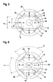
- the Fig. 1 to 6 each show a schematic representation of a rotor 10 of a permanent magnet-excited electric induction machine. Shown is in each case a section along a plane perpendicular to the axis 11 of the rotor 10. In addition to the rotor 10, in each case the circular inner contour 25 of a stator is shown. In each of the Fig. 1 to 6 are the axis 11 (perpendicular to the plane) of the rotor 10, a shaft 12 and a magnetic flux conductor 13 with a plurality of poles 14 are shown. Each pole 14 has an outer contour 15. In the vicinity of at least one pole 15, the magnetic flux conductor 13 has a recess 16 and two elastic sections 17.
- each have a permanent magnet 18 is arranged in a recess 16 only at each second pole 14.
- a permanent magnet 18 is provided in a recess 16 only at each second pole 14.
- the poles 19 are referred to without a permanent magnet and without recess as a follower poles.
- the magnetic flux guide 13 comprises, for example, a magnetically soft iron or other low-hysteresis ferromagnetic material. If the material of the magnetic flux conductor 13 has an electrical conductivity, the magnetic flux conductor 13 can be constructed from a stack of thin sheets, which are separated from one another by thin insulator layers, in order to avoid eddy current losses.
- the outer contour 15 of each pole 14 is circular arc-shaped or substantially circular arc-shaped.
- the tangent of the outer contour 15 is in the middle of each pole 14, 19 perpendicular or substantially perpendicular to the direction of the magnetic flux. As the distance to the center of the pole 14 increases, the magnetic flux on the outer contour 15 deviates from the perpendicular to the tangent of the outer contour 15.
- the recesses 16 and the permanent magnets 18 arranged therein each have essentially the shape of flat cuboids in the illustrated examples.
- at least two parallel, large, substantially planar sections of the outer surface of a magnet 18 can abut against two essentially parallel sections of a surface of the recess 16.
- These substantially planar portions of the surfaces of the permanent magnets 18 and the recesses 16 are each substantially perpendicular to the local direction of the magnetic flux.
- the elastic portions 17 of the magnetic flux guide 13 are in the in the Fig. 1 to 6 shown examples in pairs on both sides of each pole 14 and have the form of narrow straight or slightly curved ridges.
- Fig. 1 and 2 show schematic representations of a rotor 10 in two different phases or states in the production.
- Fig. 1 shows a state in which the recess 16 is widened.
- the recess 16 is for example by a in the Fig. 1 and 2 not shown tool widened, which engages in engaging portions 31 on both sides of the pole 14 and there exerts an indicated by arrows 40 expanding force.
- the thickness of the flared recess 16 is greater than or equal to the thickness of the permanent magnet 18 Fig. 1 this is indicated by a gap between the permanent magnet 18 and a wall of the recess 16.
- the permanent magnet 18 can be inserted into the widened recess 16.
- the expanding force 40 is removed.
- the expansion of the recess 16 is reversed by elastic restoring forces of the elastic portions 17 of the magnetic flux conductor 13.
- the thickness or height of the recess 16, the thickness of the permanent magnet 18 and - so far freely selectable - whose tolerance intervals or tolerance ranges are selected so that the minimum thickness within the tolerance interval of the thickness of the permanent magnet 18 is greater than or equal to the maximum thickness or Height within the tolerance interval of the thickness or height of the recess 16 is.
- the permanent magnet 18 is held in the recess 16 by the magnetic attraction force between the permanent magnet 18 and the magnetic flux guide 13 and / or by the forces exerted by the elastic portions 17 and by the resulting static friction between the permanent magnet 18 and the magnetic flux guide 13.
- a backup by means of adhesive or sheet metal nose is not required, but can be done in addition.
- the centers of the outer contours 15 of the poles 14, 19 are each spaced from the axis 11 of the rotor 10.
- the air gap 29 between the outer contours of the poles 14 of the rotor 10 and the inner contour 25 of the stator therefore varies as a function of the angle. This is called a center offset arc contour.
- the width m of the permanent magnet 18, the width p of the pole 14, the minimum distance d and the maximum distance q of the outer contour 15 of the rotor 10 from the inner contour 25 of the stator are shown.
- the ratios p / m and q / d can be found below using the FIGS. 5 and 6 have values described in order to achieve the advantages also described there.
- the 3 and 4 show rotors 10, each with four permanent magnets 18 in corresponding recesses 16.
- the outer contours 15 of the poles 14 are each circular arc-shaped. However, the centers of these arcs are in contrast to the above based on the Fig. 1 and illustrated embodiments on the axis 11 of the rotor 10th
- Fig. 3 are in addition to those already above based on the Fig. 1 and 2 described in pairs laterally of the pole 14 arranged engaging portions 31 on each pole alternative engaging portions 32 and alternative engaging portions 33 shown.
- the engagement portions 32 are arranged on the edge of the recess 16, the engagement portions 33 are arranged as bores in the poles 14. It is advantageous to attach the same engaging portions on all poles 14 in order to use all permanent magnets 18 with the same tools can.
- Fig. 3 the recesses 16 are shown in the expanded state, in which between the permanent magnet 18 and the magnetic flux conductor 13 in each case a gap can be seen.
- Fig. 4 is the situation shown above on the basis of Fig. 2 has been described.
- the restoring forces of the elastic portions 17 make the widening of the recesses 16 completely or partially undone.
- the permanent magnets 18 are clamped in the recesses 16 and prevented at least by stiction from falling out.
- Fig. 5 shows a schematic representation of a rotor 10 similar to the above with reference to Fig. 1 and 2 represented rotor.
- the rotor 10 has a permanent magnet 18 in each case at each pole 14 in a recess 16.
- the polarity of the permanent magnets 18 is indicated by the letters "N" and "S".
- the quotient q / d of the maximum thickness q (between two adjacent poles 14) and the minimum thickness d (at the apex of a pole 14) of the air gap between the outer contours 15 of the poles 14 on the one hand and the inner contour 25 of the stator on the other hand has a value in the interval from 2.2 to 2.4, in particular 2.3.
- the quotient p / m of the width p of a pole 14 and the width m of a permanent magnet 18 has a value in the interval from 0.74 to 0.76, in particular the value 0.75.
- Fig. 6 shows a schematic representation of a rotor 10 similar to the above with reference to Fig. 1 and 2 represented rotor.
- the quotients q / d and p / m have the same values as in the above based on the Fig. 5 represented rotor.
- the quotient ⁇ / ⁇ of the angular width ⁇ of a following pole 19 and the angular distance ⁇ between two adjacent points with maximum width q of the air gap has a value in the range of 0.58 to 0.64, in particular 0.62.
- the angular width ⁇ is the angle at which the two points at which the elastic portions 17 adjoin the follower pole 19 appear from the axis 11 of the rotor 10.
- Fig. 7 shows a schematic representation of an electrical machine 50 in a fluid pump 60.
- the electric machine 50 has a stator or a rotor, in which a permanent magnet as above with reference to Fig. 1 to 4 represented clamped by an elasticity of a magnetic flux conductor or at least inserted gap-free.
- the electric machine 50 has a rotor with the above based on the FIGS. 5 and 6 displayed parameters.
- electric machine 50 may be formed as a wet rotor.
- the rotor rotates in the fluid pumped by the fluid pump 60.
- the rotor may be enclosed, for example, in a thin-walled non-magnetic stainless steel tube.
- a plastic pipe may be arranged on the inner contour of the stator, for example, which at the same time forms part of the actual pump housing or of the fluid container.
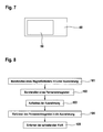
- Fig. 8 shows a schematic flow diagram of a method for producing a stator or a rotor of an electric machine. Although this method is applicable to other than the above-described machines, the reference numerals will be exemplified in the following for ease of understanding Fig. 1 to 6 used.
- a magnetic flux conductor 13 is provided with a recess 16.
- a permanent magnet 18 is provided in a second step 102.
- the recess 16 is widened by applying an expanding force 40.
- the permanent magnet is inserted into the flared recess.
- the expanding force is removed after insertion 104 of the permanent magnet 18 into the widened recess 16.
Landscapes
- Engineering & Computer Science (AREA)
- Power Engineering (AREA)
- Permanent Field Magnets Of Synchronous Machinery (AREA)
- Iron Core Of Rotating Electric Machines (AREA)
Description
- Die vorliegende Erfindung bezieht sich auf einen Stator oder Läufer einer elektrischen Dreh- oder Wanderfeldmaschine, eine elektrische Dreh- oder Wanderfeldmaschine und ein Verfahren zum Herstellen eines Stators oder eines Läufers einer elektrischen Dreh- oder Wanderfeldmaschine. Ferner bezieht sich die vorliegende Erfindung auf eine permanentmagneterregte elektrische Drehfeldmaschine und eine elektrische Fluidpumpe.
- Motorisch und/oder generatorisch betreibbare elektrische Maschinen mit rotierendem Läufer bzw. Rotor oder in linearer Bauform finden zahlreiche Anwendungen. Verschiedene Bauformen weisen Permanentmagneten im Stator bzw. Ständer oder im Läufer auf. Diese Permanentmagneten sind beispielsweise als Oberflächenmagneten, Ringmagneten oder vergrabene Magneten ausgeführt.
- Der Begriff "vergrabener Magnet" bezeichnet einen Magneten, der in einer Ausnehmung, einer Tasche oder einer Lücke eines Magnetflussleiters angeordnet ist. Der Permanentmagnet wird in die Ausnehmung, Tasche oder Lücke eingeschoben und dort beispielsweise mit Klebstoff oder Blechnasen fixiert. Ein Nachteil dieser Montage ist, dass die Ausnehmung, Tasche oder Lücke so groß sein muss, dass der Permanentmagnet auf jeden Fall eingeführt werden kann. Da sowohl bei der Ausnehmung als auch bei dem Permanentmagneten fertigungstechnisch begründete Toleranzen berücksichtigt werden müssen, verbleibt immer ein Spalt zwischen dem Permanentmagneten und dem Magnetflussleiter. Der Spalt kann zwar mit Klebstoff aufgefüllt werden, bildet jedoch einen Widerstand für den Magnetfluss.
- Aus der
DE 10 2007 029 719 ist eine elektrische Maschine bekannt geworden, bei der ein Rotor Aussparungen aufweist, in die Magnete axial eingeschoben werden. Dabei sind an der Innenwand der Aussparung federnde Ansätze angeformt, die die Magnete radial und tangential positionieren. - Für viele Anwendungen einer permanentmagneterregten elektrischen Drehfeldmaschine sind ein minimales Rastmoment, eine minimale Welligkeit des Drehmoments und ein maximales mittleres Drehmoment erwünscht. Ein minimales Rastmoment und eine minimale Welligkeit des Drehmoments werden bei einer sinusförmigen Flussdichteverteilung im Luftspalt zwischen Stator und Rotor erzielt. Die Flussdichteverteilung im Luftspalt wird maßgeblich durch die Form, insbesondere die Kontur, der Pole bzw. Polschuhe bestimmt.
- Die
JP20000197292 - Bei der von R. Richter gefundenen und nach ihm benannten Kontur des Rotorpolschuhs ist die Breite des Luftspalts zwischen Rotor und dem zylindrischen Stator eine inverse Kosinusfunktion. Die Richter-Kontur erzeugt in sehr guter Näherung die erwünschte sinusförmige Flussdichteverteilung im Luftspalt, ihre Implementierung in moderne Computerprogramme zur elektromagnetischen und mechanischen Auslegung ist jedoch aufwendig und zeitintensiv.
- Als einfacher implementierbare alternative Kontur wird die zentrumsversetzte Bogenkontur verwendet. Die Kontur des Rotorpolschuhs ist kreisbogenförmig, wobei jedoch der Mittelpunkt des Kreisbogens nicht auf der Achse des Rotors liegt, sondern gegenüber dieser radial versetzt ist.
- Eine Aufgabe der vorliegenden Erfindung besteht darin, eine verbesserte permanentmagneterregte elektrische Drehfeldmaschine ein Verfahren zum Herstellen einer solchen und eine verbesserte elektrische Fluidpumpe zu schaffen.
- Diese Aufgaben werden durch die Gegenstände der unabhängigen Ansprüche gelöst. Weiterbildungen der vorliegenden Erfindung sind in den abhängigen Ansprüchen definiert.
- Die vorliegende Erfindung beruht auf der Idee bei einer permanentmagneterregten elektrischen Drehfeldmaschine gemäss dem Oberbegriff des Anspruchs 1 einem Luftspalt zwischen der Innenkontur des Stators und der Außenkontur des Rotors zwischen zwei Polen eine maximale Breite und nahe einer Mitte eines Pols eine minimale Breite des Luftspalts so vorzusehen, dass der Quotient aus der maximalen Breite und der minimalen Breite im Bereich von 2,2 bis 2,4 liegt und ein Quotient aus einer Breite eines ersten Pols und einer Breite eines in dem ersten Pol vergrabenen Permanentmagneten im Bereich von 0,74 bis 0,76 liegt. Die Breite des ersten Pols und die Breite des Permanent-magneten werden dabei vorzugsweise in Richtung einer Sehne senkrecht zur Achse des Rotors gemessen.
- Der Permanent-magnet wird durch die Rückstellkraft einer elastischen Verformung des Magnetflussleiters in der Ausnehmung geklemmt.
- Der Permanentmagnet und die Ausnehmung weisen beispielsweise jeweils die Form eines flachen Quaders auf, dessen Oberfläche sechs im Wesentlichen rechteckige und im Wesentlichen ebene Abschnitte umfasst. Die beiden größten ebenen Abschnitte der Oberfläche des Permanentmagneten können senkrecht zum Magnetfluss und im Wesentlichen parallel zur Polfläche, an der der magnetische Fluss den Magnetflussleiter verlässt, oder zum Scheitel der Polfläche angeordnet sein. Insbesondere die Form der Ausnehmung kann von der Quaderform vor Allem an den Rändern deutlich abweichen.
- Anstelle einer jeweils im Wesentlichen quaderförmigen Gestalt können der Permanentmagnet und die Ausnehmung aber auch jeweils eine andere Form aufweisen. Dabei gibt es zumindest einen Bereich, in dem zumindest bei elastisch verformtem elastischen Abschnitt die dreidimensionalen Gestalten des Permanentmagneten und der Ausnehmung einander näherungsweise entsprechen.
- Einer oder mehrere elastische Abschnitte des Magnetflussleiters können an oder nahe bei den Rändern des Permanentmagneten angeordnet sein. Im Fall des erwähnten quaderförmigen Permanentmagneten sind beispielsweise zwei elastische Abschnitte nahe zwei kleinen ebenen Abschnitten der Oberfläche des Permanentmagneten angeordnet.
- Der oder die elastischen Abschnitte des Magnetflussleiters werden beispielsweise durch gerade oder gebogene Stege gebildet. Einer oder mehrere elastische Abschnitte können zwischen zwei Polen des Läufers angeordnet sein.
- Ferner können am Rand der Ausnehmung oder nahe derselben einer oder mehre Eingreifabschnitte vorgesehen sein. In den oder die Eingriffabschnitte kann ein Spreizwerkzeug zum elastischen Aufweiten der Ausnehmung eingreifen. Ferner können eine oder mehrere Flussbarrieren in dem Magnetflussleiter vorgesehen sein. Eingriffabschnitte und Flussbarrieren können identisch sein.
- Ein Vorteil einer Klemmung eines Permanentmagneten in einem Magnetflussleiter besteht darin, dass kein Spalt zwischen dem Permanentmagneten und dem Magnetflussleiter verbleibt. Damit wird der magnetische Widerstand der Anordnung reduziert und der magnetische Fluss in der Anordnung erhöht. Dies kommt dem mit einer elektrischen Maschine mit dem Stator oder Läufer erzielbaren Drehmoment bzw. der erzielbaren Kraft zu Gute.
- Ein weiterer Vorteil der Klemmung besteht darin, dass kein Klebstoff erforderlich ist und keine Blechnase gebogen werden muss. Allerdings kann zusätzlich Klebstoff verwendet werden. Durch die Wirkung der elastischen Rückstellkraft kann der Klebstoff jedoch bis auf einen sehr dünnen Film aus dem Zwischenraum zwischen Permanentmagnet und Magnetflussleiter verdrängt werden. Die Menge des erforderlichen Klebstoffs wird dadurch reduziert.
- Um die beschriebene Klemmung zu erzielen, werden die nominalen Abmessungen des Permanentmagneten und der Ausnehmung und - insoweit frei wählbar - die Toleranzintervalle dieser Abmessungen so gewählt, dass die minimale Dicke innerhalb eines Toleranzintervalls der Dicke des Permanentmagneten größer oder gleich einer maximalen Dicke innerhalb eines Toleranzintervalls der Dicke der Ausnehmung bei entspanntem elastischem Abschnitt ist. Die Dicke wird dabei in der Richtung gemessen, in der die Geometrie der Ausnehmung elastisch veränderbar ist. Bei einigen Ausführungsformen ist die gleichzeitig die Richtung des Magnetfelds. Durch diese Auslegung wird sichergestellt, dass die Dicke des Permanentmagneten größer oder gleich der Dicke der Ausnehmung ist. Die Oberflächen der Ausnehmung liegen damit zumindest an dem Permanentmagneten an oder üben sogar eine pressende Kraft auf diese aus.
- Insbesondere bei einer minimalen Breite des Luftspalts im Bereich von 2,0 mm bis 2,5 mm und einem maximalen Rotordurchmesser im Bereich von 30 mm bis 50 mm hat sich herausgestellt, dass mit diesen Parametern nicht nur ein überraschend geringes Rastmoment und eine überraschend geringe Welligkeit des Drehmoments, sondern auch ein hohes mittleres Drehmoment erzielbar sind. Das erzielbare mittlere Drehmoment liegt sogar über dem, das mit einem Rotor mit Richter-Kontur erzielbar wäre.
- Wenn der Rotor der Drehfeldmaschine eine Folgepolanordnung mit zwei Permanentmagnetpolen und zwei Folgepolen aufweist, ist eine Breite des Folgepols zwischen 0,58 x π elektrische rad und 0,64 x π elektrische rad optimal. Mit den genannten Parametern eignet sich die Drehfeldmaschine besonders als Nassläufermaschine zum Antreiben einer Kühlmittelpumpe oder einer anderen Fluidpumpe in einem Kraftfahrzeug oder für eine andere Anwendung.
- Ausführungsbeispiele werden nachfolgend mit Bezug auf die Figuren näher erläutert. Es zeigen:
- Fig. 1
- eine schematische Darstellung eines Rotors einer elektrischen Drehfeldmaschine bei der Montage eines Permanentmagneten;
- Fig. 2
- eine schematische Darstellung des Rotors aus
Fig. 1 nach der Montage; - Fig. 3
- eine schematische Darstellung eines Rotors einer weiteren elektrischen Drehfeldmaschine bei der Montage von Permanentmagneten;
- Fig. 4
- eine schematische Darstellung des Rotors aus
Fig. 3 nach der Montage; - Fig. 5
- eine schematische Darstellung eines Rotors einer elektrischen Drehfeldmaschine;
- Fig. 6
- eine schematische Darstellung eines Rotors einer elektrischen Drehfeldmaschine in Folgpolanordnung;
- Fig. 7
- eine schematische Darstellung einer Fluidpumpe mit einer permanentmagneterregten elektrischen Drehfeldmaschine; und
- Fig. 8
- ein schematisches Flussdiagramm eines Verfahrens zum Herstellen eines Stators oder Läufers einer elektrischen Maschine.
- Die
Fig. 1 bis 6 zeigen jeweils eine schematische Darstellung eines Rotors 10 einer permanentmagneterregten elektrischen Drehfeldmaschine. Dargestellt ist jeweils ein Schnitt entlang einer Ebene senkrecht zur Achse 11 des Rotors 10. Neben dem Rotor 10 ist jeweils auch die kreisförmige Innenkontur 25 eines Stators dargestellt. In jeder derFig. 1 bis 6 sind die Achse 11 (senkrecht zur Zeichenebene) des Rotors 10, eine Welle 12 und ein Magnetflussleiter 13 mit mehreren Polen 14 dargestellt. Jeder Pol 14 weist eine Außenkontur 15 auf. In der Nähe mindestens eines Pols 15 weist der Magnetflussleiter 13 eine Ausnehmung 16 und zwei elastische Abschnitte 17 auf. In einer Ausnehmung 16 ist jeweils ein Permanent-magnet 18 angeordnet. Bei den in denFig. 1, 2 und6 dargestellten Rotoren 10 ist nur an jedem zweiten Pol 14 ein Permanentmagnet 18 in einer Ausnehmung 16 vorgesehen. In diesem Fall werden die Pole 19 ohne Permanentmagnet und ohne Ausnehmung als Folgepole bezeichnet. - Der Magnetflussleiter 13 weist beispielsweise ein magnetisch weiches Eisen oder ein anderes ferromagnetisches Material mit geringer Hysterese auf. Wenn das Material des Magnetflussleiters 13 eine elektrische Leitfähigkeit aufweist, kann der Magnetflussleiter 13 aus einem Stapel dünner Bleche bzw. Schichten aufgebaut sein, die jeweils durch dünne Isolatorschichten voneinander getrennt sind, um Wirbelstromverluste zu vermeiden.
- Die Außenkontur 15 jedes Pols 14 ist kreisbogenförmig oder im Wesentlichen kreisbogenförmig. Die Tangente der Außenkontur 15 ist in der Mitte jedes Pols 14, 19 senkrecht oder im Wesentlichen senkrecht zur Richtung des Magnetflusses. Mit zunehmendem Abstand zur Mitte des Pols 14 weicht der Magnetfluss an der Außenkontur 15 von der Senkrechten auf die Tangente der Außenkontur 15 ab.
- Die Ausnehmungen 16 und die darin angeordneten Permanentmagneten 18 weisen bei den dargestellten Beispielen jeweils im Wesentlichen die Form flacher Quader auf. Dabei können zumindest zwei parallele, große im Wesentlichen ebene Abschnitte der Außenfläche eines Magnets 18 an zwei im Wesentlichen parallelen Abschnitten einer Oberfläche der Ausnehmung 16 anliegen. Diese im Wesentlichen ebenen Abschnitte der Oberflächen der Permanentmagneten 18 und der Ausnehmungen 16 sind jeweils im Wesentlichen senkrecht zur lokalen Richtung des Magnetflusses.
- Die elastischen Abschnitte 17 des Magnetflussleiters 13 sind bei den in den
Fig. 1 bis 6 dargestellten Beispielen jeweils paarweise zu beiden Seiten jedes Pols 14 angeordnet und weisen die Form schmaler gerader oder leicht gekrümmter Stege auf. - Die
Fig. 1 und 2 zeigen schematische Darstellungen eines Rotors 10 in zwei verschiedenen Phasen bzw. Zuständen bei der Herstellung.Fig. 1 zeigt einen Zustand, in dem die Ausnehmung 16 aufgeweitet ist. Die Ausnehmung 16 wird beispielsweise durch ein in denFig. 1 und 2 nicht dargestelltes Werkzeug aufgeweitet, das in Eingreifabschnitte 31 zu beiden Seiten des Pols 14 eingreift und dort eine durch Pfeile 40 angedeutete aufweitende Kraft ausübt. Die Dicke der aufgeweiteten Ausnehmung 16 ist größer oder gleich der Dicke des Permanentmagneten 18. InFig. 1 wird dies durch einen Spalt zwischen dem Permanentmagneten 18 und einer Wand der Ausnehmung 16 angedeutet. Der Permanentmagnet 18 kann in die aufgeweitete Ausnehmung 16 eingesetzt werden. - Nach dem Einsetzen des Permanentmagneten 18 in die Ausnehmung 16 wird die aufweitende Kraft 40 entfernt. Die Aufweitung der Ausnehmung 16 wird durch elastische Rückstellkräfte der elastischen Abschnitte 17 des Magnetflussleiters 13 rückgängig gemacht. Wie in
Fig. 2 dargestellt, liegen die Wände der Ausnehmung 16 dann an den entsprechenden Oberflächen des Permanentmagneten 18 an oder üben sogar eine Kraft auf diese aus. Dazu werden die Dicke bzw. Höhe der Ausnehmung 16, die Dicke des Permanentmagneten 18 und - soweit frei wählbar - deren Toleranzintervalle bzw. Toleranzbereiche so gewählt, dass die minimale Dicke innerhalb des Toleranzintervalls der Dicke des Permanentmagneten 18 größer oder gleich der maximalen Dicke bzw. Höhe innerhalb des Toleranzintervalls der Dicke bzw. Höhe der Ausnehmung 16 ist. - Bei dem in
Fig. 2 dargestellten Zustand wird der Permanentmagnet 18 durch die magnetische Anziehungskraft zwischen dem Permanentmagneten 18 und dem Magnetflussleiter 13 und/oder durch die von den elastischen Abschnitten 17 ausgeübten Kräfte sowie durch die resultierende Haftreibung zwischen dem Permanentmagneten 18 und dem Magnetflussleiter 13 in der Ausnehmung 16 gehalten. Eine Sicherung mittels Klebstoff oder Blechnasen ist nicht erforderlich, kann jedoch zusätzlich erfolgen. - Bei dem oben anhand der
Fig. 1 und 2 dargestellten Beispiel sind die Mittelpunkte der Außenkonturen 15 der Pole 14, 19 jeweils von der Achse 11 des Rotors 10 beabstandet. Der Luftspalt 29 zwischen den Außenkonturen der Pole 14 des Rotors 10 und der Innenkontur 25 des Stators variiert deshalb als Funktion des Winkels. Dies wird als zentrumsversetzte Kreisbogenkontur bezeichnet. InFig. 2 sind die Breite m des Permanentmagneten 18, die Breite p des Pols 14, der minimale Abstand d und der maximale Abstand q der Außenkontur 15 des Rotors 10 von der Innenkontur 25 des Stators dargestellt. Die Verhältnisse p/m und q/d können die unten anhand derFig. 5 und 6 beschriebenen Werte aufweisen, um die ebenfalls dort beschriebenen Vorteile zu erzielen. - Die
Fig. 3 und 4 zeigen Rotoren 10 mit jeweils vier Permanentmagneten 18 in entsprechenden Ausnehmungen 16. Die Außenkonturen 15 der Pole 14 sind jeweils kreisbogenförmig. Die Mittelpunkte dieser Kreisbögen liegen jedoch im Gegensatz zu den oben anhand derFig. 1 und dargestellten Ausführungsbeispiele auf der Achse 11 des Rotors 10. - In
Fig. 3 sind neben den bereits oben anhand derFig. 1 und 2 beschriebenen paarweise seitlich der Pole 14 angeordneten Eingreifabschnitten 31 an jeweils einem Pol alternative Eingreifabschnitte 32 und alternative Eingreifabschnitte 33 dargestellt. Die Eingreifabschnitte 32 sind am Rand der Ausnehmung 16 angeordnet, die Eingreifabschnitte 33 sind als Bohrungen in den Polen 14 angeordnet. Vorteilhaft ist eine Anbringung gleicher Eingreifabschnitte an allen Polen 14, um alle Permanentmagneten 18 mit gleichen Werkzeugen einsetzen zu können. - In
Fig. 3 sind die Ausnehmungen 16 im aufgeweiteten Zustand dargestellt, in dem zwischen dem Permanentmagneten 18 und dem Magnetflussleiter 13 jeweils ein Spalt erkennbar ist. InFig. 4 ist die Situation dargestellt, die bereits oben anhand derFig. 2 beschrieben wurde. Die Rückstellkräfte der elastischen Abschnitte 17 machen die Aufweitung der Ausnehmungen 16 ganz oder teilweise rückgängig. Die Permanentmagneten 18 sind in den Ausnehmungen 16 geklemmt und zumindest durch Haftreibung am Herausfallen gehindert. -
Fig. 5 zeigt eine schematische Darstellung eines Rotors 10 ähnlich dem oben anhand derFig. 1 und 2 dargestellten Rotor. Im Gegensatz zu letzterem weist der Rotor 10 hier jedoch an jedem Pol 14 einen Permanentmagneten 18 in einer Ausnehmung 16 auf. Die Polung der Permanentmagneten 18 ist durch die Buchstaben "N" und "S" gekennzeichnet. Der Quotient q/d der maximalen Dicke q (zwischen zwei benachbarten Polen 14) und der minimalen Dicke d (am Scheitel eines Pols 14) des Luftspalts zwischen den Außenkonturen 15 der Pole 14 einerseits und der Innenkontur 25 des Stators andererseits weist einen Wert im Intervall von 2,2 bis 2,4, insbesondere den Wert 2,3 auf. Der Quotient p/m der Breite p eines Pols 14 und der Breite m eines Permanentmagneten 18 weist einen Wert im Intervall von 0,74 bis 0,76, insbesondere den Wert 0,75 auf. -
Fig. 6 zeigt eine schematische Darstellung eines Rotors 10 ähnlich dem oben anhand derFig. 1 und 2 dargestellten Rotor. Die Quotienten q/d und p/m weisen die gleichen Werte auf wie bei dem oben anhand derFig. 5 dargestellten Rotor. Der Quotient α/β der Winkelbreite α eines Folgepols 19 und dem Winkelabstand β zwischen zwei benachbarten Punkten mit maximaler Breite q des Luftspalts weist einen Wert im Bereich von 0,58 bis 0,64, insbesondere den Wert 0,62 auf. Dabei gilt bei insgesamt vier Polen 14, 19 beispielsweise β = π/2 = 90°. Die Winkelbreite α ist der Winkel unter dem die beiden Punkte, an denen die elastischen Abschnitte 17 an den Folgepol 19 grenzen, von der Achse 11 des Rotors 10 aus erscheinen. - Es hat sich gezeigt, dass bei den anhand der
Fig. 5 und 6 dargestellten Quotienten q/d, p/m, α/β ein besonders geringes Rastmoment, eine besonders geringe Welligkeit des Drehmoments und ein besonders hohes mittleres Drehmoment erzielbar sind. Dies gilt insbesondere bei einer minimalen Breite d des Luftspalts von d = 2,3 mm und bei einem Durchmesser des Rotors 10 im Bereich von 30 mm bis 50 mm. Das Rastmoment und die Welligkeit des Drehmoments liegen im Bereich einer permanentmagneterregten elektrischen Drehfeldmaschine mit Richter-Kontur, das mittlere Drehmoment ist sogar höher als im Fall einer Richter-Kontur. Bei den anhand derFig. 5 und 6 dargestellten Rotoren müssen die Permanentmagneten 18 nicht wie oben anhand derFig. 1 bis 4 dargestellt, geklemmt, sondern können auch nur geklebt oder mit Blechnasen oder auf andere Weise fixiert sein. - Die oben anhand der
Fig. 1 bis 4 dargestellte Klemmung eines Permanentmagneten in einer Ausnehmung eines Magnetflussleiters ist nicht nur bei einer permanentmagneterregten elektrischen Drehfeldmaschine, sondern beispielsweise auch am Stator bzw. Ständer eines Gleichstrommotors oder -generators und an einer permanentmagneterregten elektrischen Wanderfeldmaschine bzw. einem Linearmotor oder -generator anwendbar. -
Fig. 7 zeigt eine schematische Darstellung einer elektrischen Maschine 50 in einer Fluidpumpe 60. Die elektrische Maschine 50 weist einen Stator oder einen Rotor auf, bei dem ein Permanentmagnet wie oben anhand derFig. 1 bis 4 dargestellt durch eine Elastizität eines Magnetflussleiters geklemmt oder zumindest spaltfrei eingesetzt ist. Alternativ oder zusätzlich weist die elektrische Maschine 50 einen Rotor mit den oben anhand derFig. 5 und 6 dargestellten Parametern auf. - Die in
Fig. 7 dargestellte elektrische Maschine 50 kann als Nassläufer ausgebildet sein. Dabei rotiert der Rotor in dem von der Fluidpumpe 60 geförderten Fluid. Zum Schutz des Magnetflussleiters und/oder der Permanentmagneten vor dem Fluid kann der Rotor beispielsweise in eine dünnwandiges nichtmagnetisches Edelstahlrohr eingeschlossen sein. Zum Schutz des Stators und/oder von dessen Wicklungen vor dem Fluid kann an der Innenkontur des Stators beispielsweise ein Kunststoffrohr angeordnet sein, das gleichzeitig einen Teil des eigentlichen Pumpengehäuses oder des Fluidbehälters bildet. -
Fig. 8 zeigt ein schematisches Flussdiagramm eines Verfahrens zum Herstellen eines Stators oder eines Läufers einer elektrischen Maschine. Obwohl dieses Verfahren auch auf andere als die oben dargestellten Maschinen anwendbar ist, werden nachfolgend zur Vereinfachung des Verständnisses beispielhaft die Bezugszeichen aus denFig. 1 bis 6 verwendet. - Bei einem ersten Schritt 101 wird ein Magnetflussleiter 13 mit einer Ausnehmung 16 bereitgestellt. Bei einem zweiten Schritt 102 wird ein Permanentmagnet 18 bereitgestellt. Bei einem dritten Schritt 103 wird die Ausnehmung 16 durch Anlegen einer aufweitenden Kraft 40 aufgeweitet. Bei einem vierten Schritt 104 wird der Permanentmagnet in die aufgeweitete Ausnehmung eingeführt. Bei einem fünften Schritt 105 wird die aufweitende Kraft nach dem Einführen 104 des Permanentmagneten 18 in die aufgeweitete Ausnehmung 16 entfernt.
- Alle oben anhand der
Fig. 1 bis 7 dargestellten Maschinen können motorisch und/oder generatorisch betrieben werden und für einen motorischen und/oder generatorischen Betrieb ausgebildet sein. Gleiches gilt für elektrische Maschinen, die nach dem anhand derFig. 8 dargestellten Herstellungsverfahren hergestellt sind.
Claims (13)
- Permanentmagneterregte elektrische Drehfeldmaschine (50), mit:einem Stator mit kreisförmiger Innenkontur (25):- einem Rotor (10) mit mehreren Polen (14, 19), deren Außenkonturen (15) kreisbogenförmig sind:- Permanentmagnete (18), die zum Erzeugen eines magnetischen Flusses in Polen (14) des Rotors (10) angeordnet sind; mit:einem Magnetflussleiter (13) zum Leiten des magnetischen Flusses;- einer Ausnehmung (16) in dem Magnetflussleiter (13), zum Aufnehmen des Permanentmagneten (18);- elastischen Abschnitten (17) des Magnetflussleiters (13),wobei die Ausnehmung (16) bei entspannten elastischen Abschnitten (17) zumindest in einer Richtung kleiner als der Permanentmagnet (18) ist gekennzeichnet durch :- einem Luftspalt (29) zwischen der Innenkontur (25) des Stators und der Außenkontur (15) des Rotors (10),wobei der Luftspalt (29) zwischen zwei Polen (14, 19) im Bereich eines Abschnitts (17) eine maximale Breite (g) und nahe einer Mitte eines Pols eine minimalen Breite (d) aufweist,wobei der Quotient (g/d) aus der maximalen Breite (g) und der minimalen Breite (d) im Bereich von 2,2 bis 2,4 liegt,wobei ein Quotient (p/m) aus einer Breite (p) des ersten Pols und einer Breite (m) des Permanentmagneten (18) im Bereich von 0,74 bis 0,76 liegt, und p in Richtung einer Sehne senkrecht zur Achse des Rotors (10) radial außerhalb des Permanentmagneten (18) gemessen wird.
- Permanentmagneterregte elektrische Drehfeldmaschine (50) nach dem vorangehenden Anspruch, bei dem der elastische Abschnitt (17) zwei gegenüberliegende Oberflächenabschnitte der Ausnehmung (16) an zwei gegenüberliegende Oberflächenabschnitte des Permanentmagneten (18) presst.
- Permanentmagneterregte elektrische Drehfeldmaschine (50) nach einem der vorangehenden Ansprüche, bei dem der elastische Abschnitt (17) stegförmig ist.
- Permanentmagneterregte elektrische Drehfeldmaschine (50) nach einem der vorangehenden Ansprüche, wobei die elastischen Abschnitte (17) zwischen zwei Polen (14, 19) angeordnet sind.
- Permanentmagneterregte elektrische Drehfeldmaschine (50) nach einem der vorangehenden Ansprüche, ferner mit:- einem Eingreifabschnitt (31, 32, 33) zum Ansetzen eines Spreizwerkzeugs zum elastischen Aufweiten der Ausnehmung (16).
- Permanentmagneterregte elektrische Drehfeldmaschine (50)) nach einem der vorangehenden Ansprüche, wobei die minimale Breite (d) des Luftspalts im Bereich von 2,0 mm bis 2,5 mm liegt.
- Permanentmagneterregte elektrische Drehfeldmaschine (50)) nach einem der vorangehenden Ansprüche, wobei der Rotor (10) einen Durchmesser im Bereich von 30 mm bis 50 mm aufweist.
- Permanentmagneterregte elektrische Drehfeldmaschine (50) nach einem der vorangehenden Ansprüche, wobei die Drehfeldmaschine einen Rotor (10) mit Folgepolanordnung mit zwei Permanentmagnetpolen (14) und zwei Folgepolen (19) aufweist, und wobei der Quotient (α/β) aus der Winkelbreite (α) eines Folgepols (19) und dem Winkelabstand (β) zwischen zwei Orten mit maximaler Breite (q) des Luftspalts (29) im Bereich von 0,58 und 0,64 liegt.
- Permanentmagneterregte elektrische Drehfeldmaschine (50) nach einem der vorangehenden Ansprüche, wobei die Drehfeldmaschine eine Nassläufermaschine ist.
- Elektrische Fluidpumpe (60) mit einer permanentmagneterregten elektrischen Drehfeldmaschine (50) nach einem der vorangehenden Ansprüche.
- Verfahren zum Herstellen einer permanentmagneterregten elektrischen Drehfeldmaschine (50) nach einem der vorangehenden Ansprüche mit folgenden Schritten:- Bereitstellen (101) eines Magnetflussleiters (13) mit einer Ausnehmung (16);- Bereitstellen (102) eines Permanentmagneten (18);- elastisch Aufweiten (103) der Ausnehmung (16) durch Anlegen einer aufweitenden Kraft (40);- Einführen (104) des Permanentmagneten (18) in die aufgeweitete Ausnehmung (16);- Entfernen (105) der aufweitenden Kraft nach dem Einführen (104) des Permanentmagneten (18).
- Verfahren nach dem vorangehenden Anspruch bei dem das elastische Aufweiten (103) der Ausnehmung (16) ein elastisches Verformen eines elastischen Abschnitts (17) des Magnetflussleiters (13) umfasst.
- Verfahren nach Anspruch 11 oder 12, bei dem eine nominale Dicke des Permanentmagneten (18) und eine nominale Dicke der Ausnehmung (16) so gewählt werden, dass eine minimale Dicke innerhalb eines Toleranzintervalls der Dicke des Permanentmagneten (18) größer oder gleich einer maximalen Dicke innerhalb eines Toleranzintervalls der Dicke der Ausnehmung (16) bei entspanntem elastischem Abschnitt (17) ist.
Applications Claiming Priority (2)
| Application Number | Priority Date | Filing Date | Title |
|---|---|---|---|
| DE200810041660 DE102008041660A1 (de) | 2008-08-28 | 2008-08-28 | Stator oder Läufer einer elektrischen Dreh- oder Wanderfeldmaschine |
| PCT/EP2009/059130 WO2010023029A2 (de) | 2008-08-28 | 2009-07-16 | Stator oder läufer einer elektrischen dreh- oder wanderfeldmaschine |
Publications (2)
| Publication Number | Publication Date |
|---|---|
| EP2319161A2 EP2319161A2 (de) | 2011-05-11 |
| EP2319161B1 true EP2319161B1 (de) | 2013-04-03 |
Family
ID=41571291
Family Applications (1)
| Application Number | Title | Priority Date | Filing Date |
|---|---|---|---|
| EP09780690A Not-in-force EP2319161B1 (de) | 2008-08-28 | 2009-07-16 | Stator oder läufer einer elektrischen dreh- oder wanderfeldmaschine |
Country Status (3)
| Country | Link |
|---|---|
| EP (1) | EP2319161B1 (de) |
| DE (1) | DE102008041660A1 (de) |
| WO (1) | WO2010023029A2 (de) |
Families Citing this family (7)
| Publication number | Priority date | Publication date | Assignee | Title |
|---|---|---|---|---|
| CA2734602C (en) * | 2008-08-28 | 2016-01-05 | Seabased Ab | A wave-power unit, and a use of a such |
| DE102010029251A1 (de) * | 2010-05-25 | 2011-12-01 | Robert Bosch Gmbh | Komponente für eine elektriche Maschine sowie Verfahren und Blechlamelle zum Aufbau einer solchen Komponente |
| DE102011101730A1 (de) * | 2010-06-04 | 2011-12-08 | Ebm-Papst St. Georgen Gmbh & Co. Kg | Elektromotor |
| DE102010041015A1 (de) | 2010-09-20 | 2012-03-22 | Robert Bosch Gmbh | Maschinenkomponente für eine elektrische Maschine |
| DE102012016927A1 (de) | 2012-08-27 | 2014-02-27 | Volkswagen Aktiengesellschaft | Rotor einer elektrischen Maschine mit darin angeordneten Permanentmagneten sowie Montageverfahren zur Fixierung von Permanentmagneten in dem Rotor einer elektrischen Maschine |
| KR102647099B1 (ko) * | 2018-06-08 | 2024-03-14 | 삼성전자주식회사 | 내부 영구자석 모터 |
| CN112953154A (zh) * | 2021-04-26 | 2021-06-11 | 东南大学 | 一种用于直驱式波浪发电的定子永磁横向磁通直线发电机 |
Family Cites Families (7)
| Publication number | Priority date | Publication date | Assignee | Title |
|---|---|---|---|---|
| JPH06133479A (ja) * | 1992-09-02 | 1994-05-13 | Toshiba Corp | 永久磁石ロータ及びその製造装置 |
| JP3308828B2 (ja) * | 1996-10-18 | 2002-07-29 | 株式会社日立製作所 | 永久磁石回転電機及びそれを用いた電動車両 |
| JP2000197292A (ja) * | 1998-10-21 | 2000-07-14 | Mitsubishi Electric Corp | 永久磁石型電動機の永久磁石型回転子 |
| JP3659055B2 (ja) * | 1999-03-26 | 2005-06-15 | 日産自動車株式会社 | 電動機のロータ |
| JP2004289905A (ja) * | 2003-03-20 | 2004-10-14 | Isuzu Motors Ltd | 回転電機 |
| DE102005002332A1 (de) * | 2005-01-18 | 2006-07-27 | Daimlerchrysler Ag | Rotor für eine permanenterregte elektrische Maschine |
| DE102007029719A1 (de) * | 2007-02-01 | 2008-08-07 | Robert Bosch Gmbh | Elektrische Maschine |
-
2008
- 2008-08-28 DE DE200810041660 patent/DE102008041660A1/de not_active Withdrawn
-
2009
- 2009-07-16 EP EP09780690A patent/EP2319161B1/de not_active Not-in-force
- 2009-07-16 WO PCT/EP2009/059130 patent/WO2010023029A2/de not_active Ceased
Also Published As
| Publication number | Publication date |
|---|---|
| DE102008041660A1 (de) | 2010-03-04 |
| EP2319161A2 (de) | 2011-05-11 |
| WO2010023029A3 (de) | 2010-12-23 |
| WO2010023029A2 (de) | 2010-03-04 |
Similar Documents
| Publication | Publication Date | Title |
|---|---|---|
| DE68921721T2 (de) | Elektronisch kommutierter Motor und dafür feststehender Anker mit Schlitzen aufweisenden Zähnen und mit einer Schräge zwischen den Nuten und dem permanenten Magnetfeld zum Abschwächen des pulsierenden Drehmoments. | |
| DE19507233C2 (de) | Transversalflußmaschine mit Permanenterregung und mehrsträngiger Ankerwicklung | |
| DE112013006500B4 (de) | Drehender elektrischer Mechanismus der Permanentmagnetbauart | |
| DE112015001725T5 (de) | Drehende elektrische Maschine mit eingebetteten Permanentmagneten | |
| DE19936361A1 (de) | Permanentmagnetmotor | |
| DE19633209A1 (de) | Verfahren und Vorrichtung zur Reduzierung des sogenannten Nutruckens bei einem Elektromotor | |
| DE112008001226T5 (de) | Rotor einer rotierenden elektrischen Maschine und Fertigungsverfahren dafür | |
| EP2192670A1 (de) | Permanenterregte Synchronmaschine mit 10 Polen, 12 Nuten und optimierter Läufergeometrie | |
| EP2319161A2 (de) | Stator oder läufer einer elektrischen dreh- oder wanderfeldmaschine | |
| DE102008018724A1 (de) | Sekundärteil für eine permanentmagneterregte Synchronmaschine | |
| DE102019214623B4 (de) | Synchronmaschine, elektrische Antriebseinrichtung umfassend eine Synchronmaschine, sowie Ansteuerverfahren für eine Synchronmaschine | |
| EP1657801A2 (de) | Rotoranordnung für eine elektrische Maschine und Verfahren zur Herstellung einer Rotoranordnung | |
| EP1916754A2 (de) | Transversalflussmaschine und Verfahren zur Herstellung derselben | |
| WO2014040893A2 (de) | Rotor für eine permanenterregte elektrische maschine sowie dessen verwendung | |
| WO2013131795A2 (de) | Rotor und elektrische maschine | |
| DE102013200476A1 (de) | Permanenterregte Synchronmaschine mit einem Rotor mit Permanentmagneten und Verfahren zur Herstellung derartiger Maschinen bzw. Rotoren | |
| WO2013087412A1 (de) | Transversalflussmaschine mit halbach-arrays | |
| EP3404804B1 (de) | Elektrischer antriebsmotor mit verringerter geräuschentwicklung sowie diesen enthaltendes haushaltsgerät | |
| DE102016212022A1 (de) | Rotor | |
| WO2014049007A1 (de) | Aktivteil einer elektrischen maschine, radialmagnetlager und verfahren zur herstellung eines radialmagnetlagers | |
| EP2131475A2 (de) | Rotor für eine elektrische Maschine | |
| EP2704294A1 (de) | Rotor einer permanenterregten Synchronmaschine | |
| DE102017201029A1 (de) | Rotor für elektrische Maschine | |
| DE102019214434A1 (de) | Rotor einer elektrischen Maschine | |
| DE19781789B4 (de) | Selbststartender bürstenloser Elektromotor |
Legal Events
| Date | Code | Title | Description |
|---|---|---|---|
| PUAI | Public reference made under article 153(3) epc to a published international application that has entered the european phase |
Free format text: ORIGINAL CODE: 0009012 |
|
| AK | Designated contracting states |
Kind code of ref document: A2 Designated state(s): AT BE BG CH CY CZ DE DK EE ES FI FR GB GR HR HU IE IS IT LI LT LU LV MC MK MT NL NO PL PT RO SE SI SK SM TR |
|
| AX | Request for extension of the european patent |
Extension state: AL BA RS |
|
| 17P | Request for examination filed |
Effective date: 20110624 |
|
| RBV | Designated contracting states (corrected) |
Designated state(s): AT BE BG CH CY CZ DE DK EE ES FI FR GB GR HR HU IE IS IT LI LT LU LV MC MK MT NL NO PL PT RO SE SI SK SM TR |
|
| DAX | Request for extension of the european patent (deleted) | ||
| GRAP | Despatch of communication of intention to grant a patent |
Free format text: ORIGINAL CODE: EPIDOSNIGR1 |
|
| GRAS | Grant fee paid |
Free format text: ORIGINAL CODE: EPIDOSNIGR3 |
|
| GRAA | (expected) grant |
Free format text: ORIGINAL CODE: 0009210 |
|
| AK | Designated contracting states |
Kind code of ref document: B1 Designated state(s): AT BE BG CH CY CZ DE DK EE ES FI FR GB GR HR HU IE IS IT LI LT LU LV MC MK MT NL NO PL PT RO SE SI SK SM TR |
|
| REG | Reference to a national code |
Ref country code: GB Ref legal event code: FG4D Free format text: NOT ENGLISH |
|
| REG | Reference to a national code |
Ref country code: CH Ref legal event code: EP Ref country code: AT Ref legal event code: REF Ref document number: 605244 Country of ref document: AT Kind code of ref document: T Effective date: 20130415 |
|
| REG | Reference to a national code |
Ref country code: IE Ref legal event code: FG4D Free format text: LANGUAGE OF EP DOCUMENT: GERMAN |
|
| REG | Reference to a national code |
Ref country code: DE Ref legal event code: R096 Ref document number: 502009006731 Country of ref document: DE Effective date: 20130529 |
|
| PG25 | Lapsed in a contracting state [announced via postgrant information from national office to epo] |
Ref country code: SI Free format text: LAPSE BECAUSE OF FAILURE TO SUBMIT A TRANSLATION OF THE DESCRIPTION OR TO PAY THE FEE WITHIN THE PRESCRIBED TIME-LIMIT Effective date: 20130403 |
|
| REG | Reference to a national code |
Ref country code: NL Ref legal event code: VDEP Effective date: 20130403 |
|
| REG | Reference to a national code |
Ref country code: LT Ref legal event code: MG4D |
|
| PG25 | Lapsed in a contracting state [announced via postgrant information from national office to epo] |
Ref country code: FI Free format text: LAPSE BECAUSE OF FAILURE TO SUBMIT A TRANSLATION OF THE DESCRIPTION OR TO PAY THE FEE WITHIN THE PRESCRIBED TIME-LIMIT Effective date: 20130403 Ref country code: NO Free format text: LAPSE BECAUSE OF FAILURE TO SUBMIT A TRANSLATION OF THE DESCRIPTION OR TO PAY THE FEE WITHIN THE PRESCRIBED TIME-LIMIT Effective date: 20130703 Ref country code: NL Free format text: LAPSE BECAUSE OF FAILURE TO SUBMIT A TRANSLATION OF THE DESCRIPTION OR TO PAY THE FEE WITHIN THE PRESCRIBED TIME-LIMIT Effective date: 20130403 Ref country code: ES Free format text: LAPSE BECAUSE OF FAILURE TO SUBMIT A TRANSLATION OF THE DESCRIPTION OR TO PAY THE FEE WITHIN THE PRESCRIBED TIME-LIMIT Effective date: 20130714 Ref country code: LT Free format text: LAPSE BECAUSE OF FAILURE TO SUBMIT A TRANSLATION OF THE DESCRIPTION OR TO PAY THE FEE WITHIN THE PRESCRIBED TIME-LIMIT Effective date: 20130403 Ref country code: PT Free format text: LAPSE BECAUSE OF FAILURE TO SUBMIT A TRANSLATION OF THE DESCRIPTION OR TO PAY THE FEE WITHIN THE PRESCRIBED TIME-LIMIT Effective date: 20130805 Ref country code: IS Free format text: LAPSE BECAUSE OF FAILURE TO SUBMIT A TRANSLATION OF THE DESCRIPTION OR TO PAY THE FEE WITHIN THE PRESCRIBED TIME-LIMIT Effective date: 20130803 Ref country code: GR Free format text: LAPSE BECAUSE OF FAILURE TO SUBMIT A TRANSLATION OF THE DESCRIPTION OR TO PAY THE FEE WITHIN THE PRESCRIBED TIME-LIMIT Effective date: 20130704 Ref country code: SE Free format text: LAPSE BECAUSE OF FAILURE TO SUBMIT A TRANSLATION OF THE DESCRIPTION OR TO PAY THE FEE WITHIN THE PRESCRIBED TIME-LIMIT Effective date: 20130403 |
|
| PG25 | Lapsed in a contracting state [announced via postgrant information from national office to epo] |
Ref country code: BG Free format text: LAPSE BECAUSE OF FAILURE TO SUBMIT A TRANSLATION OF THE DESCRIPTION OR TO PAY THE FEE WITHIN THE PRESCRIBED TIME-LIMIT Effective date: 20130703 Ref country code: HR Free format text: LAPSE BECAUSE OF FAILURE TO SUBMIT A TRANSLATION OF THE DESCRIPTION OR TO PAY THE FEE WITHIN THE PRESCRIBED TIME-LIMIT Effective date: 20130403 Ref country code: LV Free format text: LAPSE BECAUSE OF FAILURE TO SUBMIT A TRANSLATION OF THE DESCRIPTION OR TO PAY THE FEE WITHIN THE PRESCRIBED TIME-LIMIT Effective date: 20130403 Ref country code: PL Free format text: LAPSE BECAUSE OF FAILURE TO SUBMIT A TRANSLATION OF THE DESCRIPTION OR TO PAY THE FEE WITHIN THE PRESCRIBED TIME-LIMIT Effective date: 20130403 Ref country code: CY Free format text: LAPSE BECAUSE OF FAILURE TO SUBMIT A TRANSLATION OF THE DESCRIPTION OR TO PAY THE FEE WITHIN THE PRESCRIBED TIME-LIMIT Effective date: 20130403 |
|
| BERE | Be: lapsed |
Owner name: ROBERT BOSCH G.M.B.H. Effective date: 20130731 |
|
| PG25 | Lapsed in a contracting state [announced via postgrant information from national office to epo] |
Ref country code: DK Free format text: LAPSE BECAUSE OF FAILURE TO SUBMIT A TRANSLATION OF THE DESCRIPTION OR TO PAY THE FEE WITHIN THE PRESCRIBED TIME-LIMIT Effective date: 20130403 Ref country code: EE Free format text: LAPSE BECAUSE OF FAILURE TO SUBMIT A TRANSLATION OF THE DESCRIPTION OR TO PAY THE FEE WITHIN THE PRESCRIBED TIME-LIMIT Effective date: 20130403 Ref country code: SK Free format text: LAPSE BECAUSE OF FAILURE TO SUBMIT A TRANSLATION OF THE DESCRIPTION OR TO PAY THE FEE WITHIN THE PRESCRIBED TIME-LIMIT Effective date: 20130403 Ref country code: CZ Free format text: LAPSE BECAUSE OF FAILURE TO SUBMIT A TRANSLATION OF THE DESCRIPTION OR TO PAY THE FEE WITHIN THE PRESCRIBED TIME-LIMIT Effective date: 20130403 |
|
| PLBE | No opposition filed within time limit |
Free format text: ORIGINAL CODE: 0009261 |
|
| STAA | Information on the status of an ep patent application or granted ep patent |
Free format text: STATUS: NO OPPOSITION FILED WITHIN TIME LIMIT |
|
| PG25 | Lapsed in a contracting state [announced via postgrant information from national office to epo] |
Ref country code: IT Free format text: LAPSE BECAUSE OF FAILURE TO SUBMIT A TRANSLATION OF THE DESCRIPTION OR TO PAY THE FEE WITHIN THE PRESCRIBED TIME-LIMIT Effective date: 20130403 Ref country code: MC Free format text: LAPSE BECAUSE OF FAILURE TO SUBMIT A TRANSLATION OF THE DESCRIPTION OR TO PAY THE FEE WITHIN THE PRESCRIBED TIME-LIMIT Effective date: 20130403 Ref country code: RO Free format text: LAPSE BECAUSE OF FAILURE TO SUBMIT A TRANSLATION OF THE DESCRIPTION OR TO PAY THE FEE WITHIN THE PRESCRIBED TIME-LIMIT Effective date: 20130403 |
|
| REG | Reference to a national code |
Ref country code: CH Ref legal event code: PL |
|
| 26N | No opposition filed |
Effective date: 20140106 |
|
| GBPC | Gb: european patent ceased through non-payment of renewal fee |
Effective date: 20130716 |
|
| REG | Reference to a national code |
Ref country code: DE Ref legal event code: R097 Ref document number: 502009006731 Country of ref document: DE Effective date: 20140106 |
|
| REG | Reference to a national code |
Ref country code: IE Ref legal event code: MM4A |
|
| PG25 | Lapsed in a contracting state [announced via postgrant information from national office to epo] |
Ref country code: CH Free format text: LAPSE BECAUSE OF NON-PAYMENT OF DUE FEES Effective date: 20130731 Ref country code: BE Free format text: LAPSE BECAUSE OF NON-PAYMENT OF DUE FEES Effective date: 20130731 Ref country code: GB Free format text: LAPSE BECAUSE OF NON-PAYMENT OF DUE FEES Effective date: 20130716 Ref country code: LI Free format text: LAPSE BECAUSE OF NON-PAYMENT OF DUE FEES Effective date: 20130731 |
|
| PG25 | Lapsed in a contracting state [announced via postgrant information from national office to epo] |
Ref country code: IE Free format text: LAPSE BECAUSE OF NON-PAYMENT OF DUE FEES Effective date: 20130716 |
|
| PG25 | Lapsed in a contracting state [announced via postgrant information from national office to epo] |
Ref country code: SM Free format text: LAPSE BECAUSE OF FAILURE TO SUBMIT A TRANSLATION OF THE DESCRIPTION OR TO PAY THE FEE WITHIN THE PRESCRIBED TIME-LIMIT Effective date: 20130403 |
|
| PG25 | Lapsed in a contracting state [announced via postgrant information from national office to epo] |
Ref country code: TR Free format text: LAPSE BECAUSE OF FAILURE TO SUBMIT A TRANSLATION OF THE DESCRIPTION OR TO PAY THE FEE WITHIN THE PRESCRIBED TIME-LIMIT Effective date: 20130403 Ref country code: MT Free format text: LAPSE BECAUSE OF FAILURE TO SUBMIT A TRANSLATION OF THE DESCRIPTION OR TO PAY THE FEE WITHIN THE PRESCRIBED TIME-LIMIT Effective date: 20130403 |
|
| PG25 | Lapsed in a contracting state [announced via postgrant information from national office to epo] |
Ref country code: HU Free format text: LAPSE BECAUSE OF FAILURE TO SUBMIT A TRANSLATION OF THE DESCRIPTION OR TO PAY THE FEE WITHIN THE PRESCRIBED TIME-LIMIT; INVALID AB INITIO Effective date: 20090716 Ref country code: MK Free format text: LAPSE BECAUSE OF FAILURE TO SUBMIT A TRANSLATION OF THE DESCRIPTION OR TO PAY THE FEE WITHIN THE PRESCRIBED TIME-LIMIT Effective date: 20130403 Ref country code: LU Free format text: LAPSE BECAUSE OF NON-PAYMENT OF DUE FEES Effective date: 20130716 |
|
| REG | Reference to a national code |
Ref country code: AT Ref legal event code: MM01 Ref document number: 605244 Country of ref document: AT Kind code of ref document: T Effective date: 20140716 |
|
| PG25 | Lapsed in a contracting state [announced via postgrant information from national office to epo] |
Ref country code: AT Free format text: LAPSE BECAUSE OF NON-PAYMENT OF DUE FEES Effective date: 20140716 |
|
| REG | Reference to a national code |
Ref country code: FR Ref legal event code: PLFP Year of fee payment: 8 |
|
| PGFP | Annual fee paid to national office [announced via postgrant information from national office to epo] |
Ref country code: DE Payment date: 20160927 Year of fee payment: 8 |
|
| PGFP | Annual fee paid to national office [announced via postgrant information from national office to epo] |
Ref country code: FR Payment date: 20160722 Year of fee payment: 8 |
|
| REG | Reference to a national code |
Ref country code: DE Ref legal event code: R119 Ref document number: 502009006731 Country of ref document: DE |
|
| REG | Reference to a national code |
Ref country code: FR Ref legal event code: ST Effective date: 20180330 |
|
| PG25 | Lapsed in a contracting state [announced via postgrant information from national office to epo] |
Ref country code: DE Free format text: LAPSE BECAUSE OF NON-PAYMENT OF DUE FEES Effective date: 20180201 |
|
| PG25 | Lapsed in a contracting state [announced via postgrant information from national office to epo] |
Ref country code: FR Free format text: LAPSE BECAUSE OF NON-PAYMENT OF DUE FEES Effective date: 20170731 |