EP2319132B1 - Multispur fieldbus barrier arrangement - Google Patents
Multispur fieldbus barrier arrangement Download PDFInfo
- Publication number
- EP2319132B1 EP2319132B1 EP09785565A EP09785565A EP2319132B1 EP 2319132 B1 EP2319132 B1 EP 2319132B1 EP 09785565 A EP09785565 A EP 09785565A EP 09785565 A EP09785565 A EP 09785565A EP 2319132 B1 EP2319132 B1 EP 2319132B1
- Authority
- EP
- European Patent Office
- Prior art keywords
- arrangement
- trunk
- barrier
- connection
- spur
- Prior art date
- Legal status (The legal status is an assumption and is not a legal conclusion. Google has not performed a legal analysis and makes no representation as to the accuracy of the status listed.)
- Active
Links
Images
Classifications
-
- H—ELECTRICITY
- H02—GENERATION; CONVERSION OR DISTRIBUTION OF ELECTRIC POWER
- H02H—EMERGENCY PROTECTIVE CIRCUIT ARRANGEMENTS
- H02H9/00—Emergency protective circuit arrangements for limiting excess current or voltage without disconnection
- H02H9/008—Intrinsically safe circuits
-
- H—ELECTRICITY
- H01—ELECTRIC ELEMENTS
- H01R—ELECTRICALLY-CONDUCTIVE CONNECTIONS; STRUCTURAL ASSOCIATIONS OF A PLURALITY OF MUTUALLY-INSULATED ELECTRICAL CONNECTING ELEMENTS; COUPLING DEVICES; CURRENT COLLECTORS
- H01R13/00—Details of coupling devices of the kinds covered by groups H01R12/70 or H01R24/00 - H01R33/00
- H01R13/46—Bases; Cases
- H01R13/53—Bases or cases for heavy duty; Bases or cases for high voltage with means for preventing corona or arcing
-
- H—ELECTRICITY
- H01—ELECTRIC ELEMENTS
- H01R—ELECTRICALLY-CONDUCTIVE CONNECTIONS; STRUCTURAL ASSOCIATIONS OF A PLURALITY OF MUTUALLY-INSULATED ELECTRICAL CONNECTING ELEMENTS; COUPLING DEVICES; CURRENT COLLECTORS
- H01R12/00—Structural associations of a plurality of mutually-insulated electrical connecting elements, specially adapted for printed circuits, e.g. printed circuit boards [PCB], flat or ribbon cables, or like generally planar structures, e.g. terminal strips, terminal blocks; Coupling devices specially adapted for printed circuits, flat or ribbon cables, or like generally planar structures; Terminals specially adapted for contact with, or insertion into, printed circuits, flat or ribbon cables, or like generally planar structures
- H01R12/70—Coupling devices
- H01R12/7076—Coupling devices for connection between PCB and component, e.g. display
-
- H—ELECTRICITY
- H02—GENERATION; CONVERSION OR DISTRIBUTION OF ELECTRIC POWER
- H02H—EMERGENCY PROTECTIVE CIRCUIT ARRANGEMENTS
- H02H7/00—Emergency protective circuit arrangements specially adapted for specific types of electric machines or apparatus or for sectionalised protection of cable or line systems, and effecting automatic switching in the event of an undesired change from normal working conditions
- H02H7/22—Emergency protective circuit arrangements specially adapted for specific types of electric machines or apparatus or for sectionalised protection of cable or line systems, and effecting automatic switching in the event of an undesired change from normal working conditions for distribution gear, e.g. bus-bar systems; for switching devices
-
- H—ELECTRICITY
- H02—GENERATION; CONVERSION OR DISTRIBUTION OF ELECTRIC POWER
- H02H—EMERGENCY PROTECTIVE CIRCUIT ARRANGEMENTS
- H02H9/00—Emergency protective circuit arrangements for limiting excess current or voltage without disconnection
- H02H9/04—Emergency protective circuit arrangements for limiting excess current or voltage without disconnection responsive to excess voltage
Definitions
- the present invention relates to a fieldbus isolated coupler better known as a fieldbus barrier forming part of an Intrinsically Safe (IS) system for supplying power and/or signals into hazardous areas, and in particular to a multispur fieldbus barrier arrangement for supply of power and/or signals to a variety of different devices within an IS environment.
- IS Intrinsically Safe
- multispur fieldbus barrier arrangements are known having a trunk connection means for the connection of a trunk connection bus, and offering a plurality of spur outlets through which any appropriate number and variety of remote field devices can be supplied and/or addressed.
- Document DE-C-19907846 discloses a flame proof plug-in connection for a wire to a PCB.
- the present invention seeks to provide for a multispur fieldbus barrier arrangement having advantages over known such arrangements.
- a multispur fieldbus barrier arrangement having trunk connection means and in which each of a plurality of spurs is connected to the trunk by barrier and surge protector devices, wherein each barrier device comprises a removably mounted modular unit arranged for plug-in connection to the trunk by means of a flameproof connection so as to provide for a non-hazardous connection.
- the barrier device in the form of a removably mounted modular unit assists greatly in reducing the wiring, and overall size of the arrangement and, in particular, use of the aforementioned flameproof connectors in connecting to the trunk allows for the advantageous use of a multispur arrangement within a potentially hazardous environment.
- trunk connection, modular barrier units and surge protectors are disposed to be mounted onto the support means of the system.
- the support means can comprise a back plane, advantageously, the surge protectors can be removably mounted within the arrangement and without requiring neither removal of power from the trunk nor removal of power to the spur on which the surge protector is mounted.
- the multispur arrangement can include redundant modular barrier device units arranged for interconnection to spur outlets associated with a failed unit.
- the redundant modular barrier device can be arranged for interconnection to such spur outlets of the failed unit in a manner responsive to an indication of failure of the failed unit.
- the invention can further provide control means for configuring the connection of the redundant modular barrier device units to the spur outlets.
- each modular barrier unit can be arranged to provide protection for a plurality of spur outlets.
- removably mounted trunk surge protector devices and/or removably mounted terminator devices can be provided and including flameproof connectors.
- a fieidbus barrier device arranged to be removably mounted in a multispur fieldbus barrier system and between a trunk connector and spur outlets, and comprising flameproof connector means for connection to the said trunk of the system.
- the flameproof connector means comprise plug-connectors arranged for the removable mounting of the fieldbus barrier device.
- the fieldbus barrier device can include plug connector means for connection with surge protectors of the multispur fieldbus barrier system.
- the fieldbus barrier device can be arranged to be mounted by said flameproof connectors to support means of the multispur fieldbus barrier system which can comprise a back plane.
- the fieldbus barrier device can comprise a modular readily removable plug-in device.
- the present invention can therefore advantageously allow for an effective "plug and play” solution to the provision of an appropriate number of fieldbus barrier devices within a multispur fieldbus barrier arrangement and which can readily provide for redundancy within the arrangement.
- the modular plug-in fieldbus barrier devices can be easily and quickly mounted as required and so maintenance of the device, and likewise the overall system arrangement, is likewise enhanced.
- the multispur unit As regards the location of the multispur unit within hazardous areas, it is considered that it can be readily mounted within a Zone 1 environment whilst still allowing for live disconnection/reconnection. Also, when compared with the current art, the overall volume of the enclosure, and indeed the number of enclosures required, is vastly reduced having advantageous cost implications.
- any spur surge protector insertion/replacement/removal, and/or any trunk surge protector insertion/replacement/removal, and/or any terminator insertion/replacement/removal can be achieved while the system remains working.
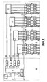
- Fig. 1 there is provided a plan view of a typical conventional sixteen spur fieldbus barrier system arranged for connection to an input trunk, and for provision of output signals on sixteen spurs.
- the sixteen spurs are divided into groups of four, each of which is provided with a signal from a four-spur barrier.
- Fig. 1 there is provided an Exe terminal block 1 and associated trunk surge protector 2, and Exde safety flameproof switches 3 each of which feeds to a respective one of the four-spur barriers which in turn have outputs connected to four spur outlets which are also fed by way of respective surge protectors 5 and terminal blocks 6.
- Each of the four-spur barriers 4 is associated with a security cover 7 serving to prevent access to, and removal of, the connection without deactivating the flameproof switches 3. Also provided connected to the terminal block 1 is a terminator unit 8.
- the actual external wiring to the spurs for the remote devices 10 leads from the respective terminal blocks 6.
- internal wiring and trunking 11 is provided for connection between external wiring 13 to the trunk and the terminal block 1 and wiring 11 is likewise provided for connection between the terminal block 1 and the safety flameproof switches 3.
- Further internal wiring 12 is provided for feeding from the flameproof switches 3 to the barriers 4 and internal wiring 14, 15 provides for connection between the barriers 4 and the terminal blocks 6 and also the surge protectors 5 and the terminal blocks 6. Also, each of the surge protectors 5 is fed directly by the external wiring 13 as illustrated.
- terminal block 8 the terminal block 8
- trunk surge protector 2 flameproof switches 3 and associated wiring connections 11 as illustrated are provided within a separate enclosure 20.
- the remainder of the system comprising the four-spur barriers 4 and associated surge protectors 5 and terminal blocks 6, and of course the associated internal wiring and elements of the external wiring 13 and internal wiring 12 as illustrated, is provided within a separate main enclosure 21.
- the extensive internal wiring and trunking 12, 13, 14, 15 disadvantageously necessitates the employment of wire, cable, two-ferrules per wire, and associated heatshrinking, trunking support, rows of terminal blocks, din rails and din rail supports which all serve to exaggerate the complexity and size of known arrangements.
- High labour costs are experienced in fitting the various mechanical parts of the system, in particular the din rails, and for stripping the wires, crimping the ferrules, heat shrinking the cable protectors that are all associated with the extensive wiring as illustrated in Fig. 1 .
- any required changes cannot all be achieved on a live basis and the fieldbus has to be powered-down, which will effectively stop the plant in which the hazardous environment is found. Any required replacement of the surge protectors 5 will require disconnection of the spur and create a risk of adjacent-channel shorts. Further, any required replacement of the trunk surge protector 2 will require either gas clearance or disconnection of the power.
- trunk-to-barrier connections 7 are changed by different personnel as compared with the remainder of the wiring and this leads to additional cost, and complexity and possibly down-time for the system.
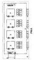
- FIG. 2 there is provided a schematic block diagram of a multispur fieldbus barrier system according to an embodiment of the present invention.
- a trunk surge protector 22 is provided along with four-spur barrier devices 24, each associated with four surge protectors 25 from which extends external wiring of spur outlets 210 to the remote located field devices on each of the sixteen spurs.
- a terminator 28 is provided, and external wiring 23 from the trunk arrives within the system, by way of the trunk surge protector 22.
- each of the trunk surge protector 22, the four-spur barrier devices 24, spur surge protectors 25 and terminator 28 are provided in a removably mounted by way of plug-in connectors to a carrier 32 which can comprise a backplane for the whole system.
- the backplane 32 includes the predefined electrical connection between the components as illustrated and thereby removes the need for the extensive wiring found in conventional systems.
- the trunk surge protector 22, and terminator 28 can likewise be provided in a plug-in fashion by way of the flameproof connectors 29 illustrated to the carrier 32 without compromising the required level of at least "Zone 1" safety.
- the terminator 28 can be provided as an integral part of the backplane carrier 32.
- the overall size of the enclosure 30 of the embodiment of Fig. 2 can therefore be greatly reduced as compared with that employed in conventional systems such as illustrated in Fig. 1 .
- Figs. 1 and 2 are connected to the connector 1 by way of jumpers or other appropriate means, in order to provide for yet further trunks 11 which, in turn, are connected to the Exed switches 3.
- the switchable trunks 12 are then, likewise in turn, connected to the barriers 5 by way of the intermediate Exe trunk connection 7.
- trunk surge protector 22 and its flame proof connectors 29 advantageously provide for the sole interface to the trunk 23 that is required for feeding all of the barrier devices 24 illustrated in Fig.2 .
- barrier devices 24 and indeed the surge protector 25, trunk surge protector 22 and terminator 28 can likewise be readily removed and replaced in a plug-in/plug-out manner whilst maintaining the required degree of safety and without requiring any down-time for the system, nor gas clearance, and without requiring only specific manual operations other than removal and replacement of the modular barrier units 24.
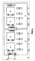
- Fig. 3 there is provided a plan view of a further embodiment of the present invention and similar reference numerals to those found previously are employed.
- two (or it readily could be more) separate carriers 32 are provided each arranged for the removable mounting of two or more multi-spur barrier devices 24 and their associated spur surge protectors 25.
- a flameproof jumper 30 which is arranged for grouping connection by way of flameproof connectors 29 engaging with sockets within the carrier 32 and which could otherwise be occupied by a terminator 28; one of which is illustrated in the right side carrier 32.
- Any appropriate number of carriers 32 can then be connected in series so as to provide for any appropriate number of spur outlets from the fieldbus barrier system of the present invention.
- an appropriate degree of redundancy can be introduced into the system by operation of a selection of one of the modular fieldbus barrier units 24 as a redundant unit.
- the failed modular barrier unit 24 can then be readily and simply unplugged without requiring power down or gas clearance for thereby simple replacement by way of a replacement barrier unit.
- surge protectors 22, 25 of the invention can be readily replaced without effecting the whole operation of the system and the terminators 28 can be introduced, removed or replaced as appropriate during commission of the system whilst the system is live.
- the modular nature of the barrier units 24 allows for replacement without the requirement for disconnecting any other barrier devices and the "plug and play" solution of the present invention greatly reduces the time that personnel need to be present on-site and any further extension to the system such as illustrated with reference to Fig. 3 , can be performed without requiring power down or gas clearance, and the ready introduction of an appropriate degree of redundancy likewise allows for live repair relevant within the system.
- the invention advantageously employs the use of flameproof connectors 29 rather than screw terminals as found in conventional systems, and indeed rather than the use of flameproof switches 3 as currently known.
- the carrier 32 provides a simplified and secure alternative option as compared with the large amount of wiring arising in the current systems and the use of live pluggable surge devices without disturbance of the functionality of the system provides a further advantage as does the use of the carrier board or back plane device for the redundancy functionality of the system.
Landscapes
- Details Of Connecting Devices For Male And Female Coupling (AREA)
- Emergency Protection Circuit Devices (AREA)
- Patch Boards (AREA)
- Respiratory Apparatuses And Protective Means (AREA)
- Connector Housings Or Holding Contact Members (AREA)
Applications Claiming Priority (2)
| Application Number | Priority Date | Filing Date | Title |
|---|---|---|---|
| GBGB0816121.8A GB0816121D0 (en) | 2008-09-04 | 2008-09-04 | Multispur fieldbus barrier arrangement |
| PCT/GB2009/051106 WO2010026419A1 (en) | 2008-09-04 | 2009-09-02 | Multispur fieldbus barrier arrangement |
Publications (2)
| Publication Number | Publication Date |
|---|---|
| EP2319132A1 EP2319132A1 (en) | 2011-05-11 |
| EP2319132B1 true EP2319132B1 (en) | 2011-11-02 |
Family
ID=39888764
Family Applications (1)
| Application Number | Title | Priority Date | Filing Date |
|---|---|---|---|
| EP09785565A Active EP2319132B1 (en) | 2008-09-04 | 2009-09-02 | Multispur fieldbus barrier arrangement |
Country Status (8)
| Country | Link |
|---|---|
| US (2) | US20110149527A1 (enExample) |
| EP (1) | EP2319132B1 (enExample) |
| JP (1) | JP5592373B2 (enExample) |
| CN (1) | CN102144340B (enExample) |
| AT (1) | ATE532234T1 (enExample) |
| ES (1) | ES2376822T3 (enExample) |
| GB (1) | GB0816121D0 (enExample) |
| WO (1) | WO2010026419A1 (enExample) |
Families Citing this family (4)
| Publication number | Priority date | Publication date | Assignee | Title |
|---|---|---|---|---|
| GB0514906D0 (en) * | 2005-07-21 | 2005-08-24 | Rogoll Gunther | Modular segment protector |
| ES2867228T3 (es) * | 2014-10-15 | 2021-10-20 | Phoenix Contact Development And Mfg Inc | Aislamiento de línea de derivación en una red de bus de campo |
| GB201603207D0 (en) * | 2016-02-24 | 2016-04-06 | Cooper Technologies Co | Electronic device configuration |
| GB201608819D0 (en) * | 2016-05-19 | 2016-07-06 | Cooper Technologies Co | Electronic device and surge handling |
Family Cites Families (10)
| Publication number | Priority date | Publication date | Assignee | Title |
|---|---|---|---|---|
| JP2525319Y2 (ja) * | 1993-05-14 | 1997-02-12 | 鹿島建設株式会社 | 無停電分電盤 |
| DE19907846C1 (de) * | 1999-02-24 | 2000-09-21 | Abb Patent Gmbh | Steckverbinder |
| US7236342B2 (en) * | 2003-07-28 | 2007-06-26 | Rockwell Automation Technologies, Inc. | In-line passive barrier for intrinsically safe communication network |
| DE10356985A1 (de) * | 2003-12-05 | 2005-07-07 | Cooper Crouse-Hinds Gmbh | Datenübertragungseinrichtung |
| JP4674855B2 (ja) * | 2005-06-29 | 2011-04-20 | 日東工業株式会社 | 筐体への電線引込構造 |
| GB0514906D0 (en) * | 2005-07-21 | 2005-08-24 | Rogoll Gunther | Modular segment protector |
| JP2007048601A (ja) * | 2005-08-10 | 2007-02-22 | Mitsubishi Electric Corp | 回路遮断器 |
| US7884495B2 (en) * | 2006-05-16 | 2011-02-08 | Honeywell International Inc. | Method and apparatus for hot swap of line replaceable modules for AC and DC electric power systems |
| JP4308276B2 (ja) * | 2007-02-05 | 2009-08-05 | レノボ・シンガポール・プライベート・リミテッド | 電子機器の接続構造および機能拡張装置 |
| US8797830B2 (en) | 2011-02-02 | 2014-08-05 | General Monitors, Inc. | Explosion-proof acoustic source for hazardous locations |
-
2008
- 2008-09-04 GB GBGB0816121.8A patent/GB0816121D0/en not_active Ceased
-
2009
- 2009-09-02 US US13/062,004 patent/US20110149527A1/en not_active Abandoned
- 2009-09-02 EP EP09785565A patent/EP2319132B1/en active Active
- 2009-09-02 JP JP2011525622A patent/JP5592373B2/ja active Active
- 2009-09-02 ES ES09785565T patent/ES2376822T3/es active Active
- 2009-09-02 AT AT09785565T patent/ATE532234T1/de active
- 2009-09-02 WO PCT/GB2009/051106 patent/WO2010026419A1/en not_active Ceased
- 2009-09-02 CN CN2009801350048A patent/CN102144340B/zh active Active
-
2015
- 2015-03-03 US US14/636,279 patent/US9755424B2/en not_active Expired - Fee Related
Also Published As
| Publication number | Publication date |
|---|---|
| EP2319132A1 (en) | 2011-05-11 |
| JP5592373B2 (ja) | 2014-09-17 |
| WO2010026419A1 (en) | 2010-03-11 |
| JP2012502609A (ja) | 2012-01-26 |
| CN102144340A (zh) | 2011-08-03 |
| US20110149527A1 (en) | 2011-06-23 |
| ES2376822T3 (es) | 2012-03-20 |
| US9755424B2 (en) | 2017-09-05 |
| CN102144340B (zh) | 2013-08-28 |
| ATE532234T1 (de) | 2011-11-15 |
| US20150180226A1 (en) | 2015-06-25 |
| GB0816121D0 (en) | 2008-10-15 |
Similar Documents
| Publication | Publication Date | Title |
|---|---|---|
| US7215535B2 (en) | Modular power distribution system for use in computer equipment racks | |
| EP1964222B1 (en) | Power distribution system with individually isolatable functional zones | |
| US8500465B1 (en) | Adaptive cable connection system | |
| EP3235103B1 (en) | Modular uninterruptible power supply and power distribution system | |
| US9755424B2 (en) | Multispur fieldbus isolator arrangement | |
| CN101854033B (zh) | 一种配电模块和配电盒 | |
| CN105932550A (zh) | 一种配电柜或配电箱的多断路器排布方法 | |
| EP1905056B1 (en) | Modular fieldbus segment protector | |
| US5638255A (en) | Power protection and distribution module | |
| CN215934516U (zh) | 用于机架的供电系统 | |
| EP3273758B1 (en) | Motor control center | |
| CA2814108C (en) | Telecommunications equipment | |
| CN113541301A (zh) | 用于机架的供电系统 | |
| WO2001067253A2 (en) | Replacement of control system i/o modules | |
| JP2018081926A (ja) | コンセントモジュール | |
| CN101782775A (zh) | 一种带有浪涌保护器的信号隔离配电器 | |
| HK1121592A (en) | Power distribution system with individually isolatable functional zones | |
| HK1121592B (en) | Power distribution system with individually isolatable functional zones | |
| KR20080113973A (ko) | 원터치 모선 부스바 | |
| CZ8192U1 (cs) | Uspořádání reléových jednotek elektronického zabezpečovacího zařízení do přístrojové skříně |
Legal Events
| Date | Code | Title | Description |
|---|---|---|---|
| PUAI | Public reference made under article 153(3) epc to a published international application that has entered the european phase |
Free format text: ORIGINAL CODE: 0009012 |
|
| 17P | Request for examination filed |
Effective date: 20110224 |
|
| AK | Designated contracting states |
Kind code of ref document: A1 Designated state(s): AT BE BG CH CY CZ DE DK EE ES FI FR GB GR HR HU IE IS IT LI LT LU LV MC MK MT NL NO PL PT RO SE SI SK SM TR |
|
| AX | Request for extension of the european patent |
Extension state: AL BA RS |
|
| GRAP | Despatch of communication of intention to grant a patent |
Free format text: ORIGINAL CODE: EPIDOSNIGR1 |
|
| GRAS | Grant fee paid |
Free format text: ORIGINAL CODE: EPIDOSNIGR3 |
|
| DAX | Request for extension of the european patent (deleted) | ||
| GRAA | (expected) grant |
Free format text: ORIGINAL CODE: 0009210 |
|
| AK | Designated contracting states |
Kind code of ref document: B1 Designated state(s): AT BE BG CH CY CZ DE DK EE ES FI FR GB GR HR HU IE IS IT LI LT LU LV MC MK MT NL NO PL PT RO SE SI SK SM TR |
|
| REG | Reference to a national code |
Ref country code: GB Ref legal event code: FG4D |
|
| REG | Reference to a national code |
Ref country code: CH Ref legal event code: EP |
|
| REG | Reference to a national code |
Ref country code: IE Ref legal event code: FG4D |
|
| REG | Reference to a national code |
Ref country code: DE Ref legal event code: R096 Ref document number: 602009003525 Country of ref document: DE Effective date: 20120126 |
|
| REG | Reference to a national code |
Ref country code: NL Ref legal event code: T3 |
|
| REG | Reference to a national code |
Ref country code: ES Ref legal event code: FG2A Ref document number: 2376822 Country of ref document: ES Kind code of ref document: T3 Effective date: 20120320 |
|
| LTIE | Lt: invalidation of european patent or patent extension |
Effective date: 20111102 |
|
| PG25 | Lapsed in a contracting state [announced via postgrant information from national office to epo] |
Ref country code: LT Free format text: LAPSE BECAUSE OF FAILURE TO SUBMIT A TRANSLATION OF THE DESCRIPTION OR TO PAY THE FEE WITHIN THE PRESCRIBED TIME-LIMIT Effective date: 20111102 Ref country code: NO Free format text: LAPSE BECAUSE OF FAILURE TO SUBMIT A TRANSLATION OF THE DESCRIPTION OR TO PAY THE FEE WITHIN THE PRESCRIBED TIME-LIMIT Effective date: 20120202 Ref country code: IS Free format text: LAPSE BECAUSE OF FAILURE TO SUBMIT A TRANSLATION OF THE DESCRIPTION OR TO PAY THE FEE WITHIN THE PRESCRIBED TIME-LIMIT Effective date: 20120302 |
|
| PG25 | Lapsed in a contracting state [announced via postgrant information from national office to epo] |
Ref country code: PL Free format text: LAPSE BECAUSE OF FAILURE TO SUBMIT A TRANSLATION OF THE DESCRIPTION OR TO PAY THE FEE WITHIN THE PRESCRIBED TIME-LIMIT Effective date: 20111102 Ref country code: PT Free format text: LAPSE BECAUSE OF FAILURE TO SUBMIT A TRANSLATION OF THE DESCRIPTION OR TO PAY THE FEE WITHIN THE PRESCRIBED TIME-LIMIT Effective date: 20120302 Ref country code: SI Free format text: LAPSE BECAUSE OF FAILURE TO SUBMIT A TRANSLATION OF THE DESCRIPTION OR TO PAY THE FEE WITHIN THE PRESCRIBED TIME-LIMIT Effective date: 20111102 Ref country code: LV Free format text: LAPSE BECAUSE OF FAILURE TO SUBMIT A TRANSLATION OF THE DESCRIPTION OR TO PAY THE FEE WITHIN THE PRESCRIBED TIME-LIMIT Effective date: 20111102 Ref country code: GR Free format text: LAPSE BECAUSE OF FAILURE TO SUBMIT A TRANSLATION OF THE DESCRIPTION OR TO PAY THE FEE WITHIN THE PRESCRIBED TIME-LIMIT Effective date: 20120203 Ref country code: SE Free format text: LAPSE BECAUSE OF FAILURE TO SUBMIT A TRANSLATION OF THE DESCRIPTION OR TO PAY THE FEE WITHIN THE PRESCRIBED TIME-LIMIT Effective date: 20111102 Ref country code: HR Free format text: LAPSE BECAUSE OF FAILURE TO SUBMIT A TRANSLATION OF THE DESCRIPTION OR TO PAY THE FEE WITHIN THE PRESCRIBED TIME-LIMIT Effective date: 20111102 |
|
| PG25 | Lapsed in a contracting state [announced via postgrant information from national office to epo] |
Ref country code: CY Free format text: LAPSE BECAUSE OF FAILURE TO SUBMIT A TRANSLATION OF THE DESCRIPTION OR TO PAY THE FEE WITHIN THE PRESCRIBED TIME-LIMIT Effective date: 20111102 |
|
| PG25 | Lapsed in a contracting state [announced via postgrant information from national office to epo] |
Ref country code: CZ Free format text: LAPSE BECAUSE OF FAILURE TO SUBMIT A TRANSLATION OF THE DESCRIPTION OR TO PAY THE FEE WITHIN THE PRESCRIBED TIME-LIMIT Effective date: 20111102 Ref country code: SK Free format text: LAPSE BECAUSE OF FAILURE TO SUBMIT A TRANSLATION OF THE DESCRIPTION OR TO PAY THE FEE WITHIN THE PRESCRIBED TIME-LIMIT Effective date: 20111102 Ref country code: DK Free format text: LAPSE BECAUSE OF FAILURE TO SUBMIT A TRANSLATION OF THE DESCRIPTION OR TO PAY THE FEE WITHIN THE PRESCRIBED TIME-LIMIT Effective date: 20111102 Ref country code: BG Free format text: LAPSE BECAUSE OF FAILURE TO SUBMIT A TRANSLATION OF THE DESCRIPTION OR TO PAY THE FEE WITHIN THE PRESCRIBED TIME-LIMIT Effective date: 20120202 Ref country code: EE Free format text: LAPSE BECAUSE OF FAILURE TO SUBMIT A TRANSLATION OF THE DESCRIPTION OR TO PAY THE FEE WITHIN THE PRESCRIBED TIME-LIMIT Effective date: 20111102 |
|
| PG25 | Lapsed in a contracting state [announced via postgrant information from national office to epo] |
Ref country code: RO Free format text: LAPSE BECAUSE OF FAILURE TO SUBMIT A TRANSLATION OF THE DESCRIPTION OR TO PAY THE FEE WITHIN THE PRESCRIBED TIME-LIMIT Effective date: 20111102 |
|
| PLBE | No opposition filed within time limit |
Free format text: ORIGINAL CODE: 0009261 |
|
| STAA | Information on the status of an ep patent application or granted ep patent |
Free format text: STATUS: NO OPPOSITION FILED WITHIN TIME LIMIT |
|
| REG | Reference to a national code |
Ref country code: AT Ref legal event code: MK05 Ref document number: 532234 Country of ref document: AT Kind code of ref document: T Effective date: 20111102 |
|
| 26N | No opposition filed |
Effective date: 20120803 |
|
| REG | Reference to a national code |
Ref country code: DE Ref legal event code: R097 Ref document number: 602009003525 Country of ref document: DE Effective date: 20120803 |
|
| PG25 | Lapsed in a contracting state [announced via postgrant information from national office to epo] |
Ref country code: AT Free format text: LAPSE BECAUSE OF FAILURE TO SUBMIT A TRANSLATION OF THE DESCRIPTION OR TO PAY THE FEE WITHIN THE PRESCRIBED TIME-LIMIT Effective date: 20111102 |
|
| PG25 | Lapsed in a contracting state [announced via postgrant information from national office to epo] |
Ref country code: MC Free format text: LAPSE BECAUSE OF NON-PAYMENT OF DUE FEES Effective date: 20120930 |
|
| REG | Reference to a national code |
Ref country code: IE Ref legal event code: MM4A |
|
| PG25 | Lapsed in a contracting state [announced via postgrant information from national office to epo] |
Ref country code: FI Free format text: LAPSE BECAUSE OF FAILURE TO SUBMIT A TRANSLATION OF THE DESCRIPTION OR TO PAY THE FEE WITHIN THE PRESCRIBED TIME-LIMIT Effective date: 20111102 |
|
| PG25 | Lapsed in a contracting state [announced via postgrant information from national office to epo] |
Ref country code: IE Free format text: LAPSE BECAUSE OF NON-PAYMENT OF DUE FEES Effective date: 20120902 |
|
| PG25 | Lapsed in a contracting state [announced via postgrant information from national office to epo] |
Ref country code: MT Free format text: LAPSE BECAUSE OF FAILURE TO SUBMIT A TRANSLATION OF THE DESCRIPTION OR TO PAY THE FEE WITHIN THE PRESCRIBED TIME-LIMIT Effective date: 20111102 |
|
| PG25 | Lapsed in a contracting state [announced via postgrant information from national office to epo] |
Ref country code: TR Free format text: LAPSE BECAUSE OF FAILURE TO SUBMIT A TRANSLATION OF THE DESCRIPTION OR TO PAY THE FEE WITHIN THE PRESCRIBED TIME-LIMIT Effective date: 20111102 |
|
| REG | Reference to a national code |
Ref country code: CH Ref legal event code: PL |
|
| PG25 | Lapsed in a contracting state [announced via postgrant information from national office to epo] |
Ref country code: SM Free format text: LAPSE BECAUSE OF FAILURE TO SUBMIT A TRANSLATION OF THE DESCRIPTION OR TO PAY THE FEE WITHIN THE PRESCRIBED TIME-LIMIT Effective date: 20111102 |
|
| PG25 | Lapsed in a contracting state [announced via postgrant information from national office to epo] |
Ref country code: CH Free format text: LAPSE BECAUSE OF NON-PAYMENT OF DUE FEES Effective date: 20130930 Ref country code: HU Free format text: LAPSE BECAUSE OF FAILURE TO SUBMIT A TRANSLATION OF THE DESCRIPTION OR TO PAY THE FEE WITHIN THE PRESCRIBED TIME-LIMIT Effective date: 20090902 Ref country code: LI Free format text: LAPSE BECAUSE OF NON-PAYMENT OF DUE FEES Effective date: 20130930 |
|
| REG | Reference to a national code |
Ref country code: FR Ref legal event code: PLFP Year of fee payment: 7 |
|
| PG25 | Lapsed in a contracting state [announced via postgrant information from national office to epo] |
Ref country code: MK Free format text: LAPSE BECAUSE OF FAILURE TO SUBMIT A TRANSLATION OF THE DESCRIPTION OR TO PAY THE FEE WITHIN THE PRESCRIBED TIME-LIMIT Effective date: 20111102 |
|
| REG | Reference to a national code |
Ref country code: FR Ref legal event code: PLFP Year of fee payment: 8 |
|
| REG | Reference to a national code |
Ref country code: FR Ref legal event code: PLFP Year of fee payment: 9 |
|
| REG | Reference to a national code |
Ref country code: FR Ref legal event code: PLFP Year of fee payment: 10 |
|
| REG | Reference to a national code |
Ref country code: GB Ref legal event code: 732E Free format text: REGISTERED BETWEEN 20181206 AND 20181212 |
|
| REG | Reference to a national code |
Ref country code: BE Ref legal event code: PD Owner name: EATON INTELLIGENT POWER LIMITED; IE Free format text: DETAILS ASSIGNMENT: CHANGE OF OWNER(S), CESSION; FORMER OWNER NAME: COOPER TECHNOLOGIES COMPANY Effective date: 20190205 |
|
| REG | Reference to a national code |
Ref country code: DE Ref legal event code: R082 Ref document number: 602009003525 Country of ref document: DE Ref country code: DE Ref legal event code: R081 Ref document number: 602009003525 Country of ref document: DE Owner name: EATON INTELLIGENT POWER LIMITED, IE Free format text: FORMER OWNER: COOPER TECHNOLOGIES COMPANY, HOUSTON, TEX., US |
|
| P01 | Opt-out of the competence of the unified patent court (upc) registered |
Effective date: 20230521 |
|
| PGFP | Annual fee paid to national office [announced via postgrant information from national office to epo] |
Ref country code: LU Payment date: 20230822 Year of fee payment: 15 |
|
| PGFP | Annual fee paid to national office [announced via postgrant information from national office to epo] |
Ref country code: NL Payment date: 20240820 Year of fee payment: 16 |
|
| PGFP | Annual fee paid to national office [announced via postgrant information from national office to epo] |
Ref country code: DE Payment date: 20240820 Year of fee payment: 16 |
|
| PGFP | Annual fee paid to national office [announced via postgrant information from national office to epo] |
Ref country code: GB Payment date: 20240822 Year of fee payment: 16 |
|
| PGFP | Annual fee paid to national office [announced via postgrant information from national office to epo] |
Ref country code: BE Payment date: 20240820 Year of fee payment: 16 |
|
| PGFP | Annual fee paid to national office [announced via postgrant information from national office to epo] |
Ref country code: FR Payment date: 20240820 Year of fee payment: 16 |
|
| PGFP | Annual fee paid to national office [announced via postgrant information from national office to epo] |
Ref country code: IT Payment date: 20240820 Year of fee payment: 16 |
|
| PGFP | Annual fee paid to national office [announced via postgrant information from national office to epo] |
Ref country code: ES Payment date: 20241001 Year of fee payment: 16 |
|
| PG25 | Lapsed in a contracting state [announced via postgrant information from national office to epo] |
Ref country code: LU Free format text: LAPSE BECAUSE OF NON-PAYMENT OF DUE FEES Effective date: 20240902 |