EP2319089B1 - Procédé et dispositif pour fabriquer une feuille à partir d'un bain fondu - Google Patents
Procédé et dispositif pour fabriquer une feuille à partir d'un bain fondu Download PDFInfo
- Publication number
- EP2319089B1 EP2319089B1 EP09807242A EP09807242A EP2319089B1 EP 2319089 B1 EP2319089 B1 EP 2319089B1 EP 09807242 A EP09807242 A EP 09807242A EP 09807242 A EP09807242 A EP 09807242A EP 2319089 B1 EP2319089 B1 EP 2319089B1
- Authority
- EP
- European Patent Office
- Prior art keywords
- sheet
- melt
- thickness
- thinning
- silicon
- Prior art date
- Legal status (The legal status is an assumption and is not a legal conclusion. Google has not performed a legal analysis and makes no representation as to the accuracy of the status listed.)
- Active
Links
- 239000000155 melt Substances 0.000 title claims description 155
- 238000000034 method Methods 0.000 title claims description 52
- 238000001816 cooling Methods 0.000 claims description 54
- XUIMIQQOPSSXEZ-UHFFFAOYSA-N Silicon Chemical compound [Si] XUIMIQQOPSSXEZ-UHFFFAOYSA-N 0.000 claims description 30
- 229910052710 silicon Inorganic materials 0.000 claims description 30
- 239000010703 silicon Substances 0.000 claims description 30
- 239000000463 material Substances 0.000 claims description 19
- 239000002699 waste material Substances 0.000 claims description 7
- 229910052732 germanium Inorganic materials 0.000 claims description 5
- GNPVGFCGXDBREM-UHFFFAOYSA-N germanium atom Chemical compound [Ge] GNPVGFCGXDBREM-UHFFFAOYSA-N 0.000 claims description 5
- 229910002601 GaN Inorganic materials 0.000 claims description 4
- GYHNNYVSQQEPJS-UHFFFAOYSA-N Gallium Chemical compound [Ga] GYHNNYVSQQEPJS-UHFFFAOYSA-N 0.000 claims description 4
- JMASRVWKEDWRBT-UHFFFAOYSA-N Gallium nitride Chemical compound [Ga]#N JMASRVWKEDWRBT-UHFFFAOYSA-N 0.000 claims description 4
- 229910052733 gallium Inorganic materials 0.000 claims description 4
- 238000009499 grossing Methods 0.000 claims description 2
- 210000004027 cell Anatomy 0.000 description 17
- 235000012431 wafers Nutrition 0.000 description 16
- 239000013078 crystal Substances 0.000 description 12
- 230000008014 freezing Effects 0.000 description 12
- 238000007710 freezing Methods 0.000 description 12
- 239000007788 liquid Substances 0.000 description 11
- 239000012530 fluid Substances 0.000 description 10
- 230000008569 process Effects 0.000 description 10
- 230000015572 biosynthetic process Effects 0.000 description 9
- 238000002425 crystallisation Methods 0.000 description 8
- 230000008025 crystallization Effects 0.000 description 8
- 238000000746 purification Methods 0.000 description 8
- 230000035882 stress Effects 0.000 description 8
- 238000000926 separation method Methods 0.000 description 7
- 210000001787 dendrite Anatomy 0.000 description 6
- 239000012535 impurity Substances 0.000 description 6
- 238000005204 segregation Methods 0.000 description 6
- 239000007787 solid Substances 0.000 description 6
- 238000002844 melting Methods 0.000 description 5
- 230000008018 melting Effects 0.000 description 5
- 229910021421 monocrystalline silicon Inorganic materials 0.000 description 5
- 230000032258 transport Effects 0.000 description 5
- 238000000605 extraction Methods 0.000 description 4
- 230000033001 locomotion Effects 0.000 description 4
- 238000004519 manufacturing process Methods 0.000 description 4
- 230000005855 radiation Effects 0.000 description 4
- 125000004429 atom Chemical group 0.000 description 3
- 230000008859 change Effects 0.000 description 3
- 229910021419 crystalline silicon Inorganic materials 0.000 description 3
- 230000000694 effects Effects 0.000 description 3
- 239000011261 inert gas Substances 0.000 description 3
- 229910021420 polycrystalline silicon Inorganic materials 0.000 description 3
- OKTJSMMVPCPJKN-UHFFFAOYSA-N Carbon Chemical compound [C] OKTJSMMVPCPJKN-UHFFFAOYSA-N 0.000 description 2
- XEEYBQQBJWHFJM-UHFFFAOYSA-N Iron Chemical compound [Fe] XEEYBQQBJWHFJM-UHFFFAOYSA-N 0.000 description 2
- 238000000137 annealing Methods 0.000 description 2
- 238000013459 approach Methods 0.000 description 2
- 230000007547 defect Effects 0.000 description 2
- 238000005516 engineering process Methods 0.000 description 2
- 230000004907 flux Effects 0.000 description 2
- 230000004927 fusion Effects 0.000 description 2
- 239000007789 gas Substances 0.000 description 2
- 229910002804 graphite Inorganic materials 0.000 description 2
- 239000010439 graphite Substances 0.000 description 2
- 230000005484 gravity Effects 0.000 description 2
- 238000010438 heat treatment Methods 0.000 description 2
- 239000001257 hydrogen Substances 0.000 description 2
- 229910052739 hydrogen Inorganic materials 0.000 description 2
- 238000005468 ion implantation Methods 0.000 description 2
- 230000007246 mechanism Effects 0.000 description 2
- 238000012986 modification Methods 0.000 description 2
- 230000004048 modification Effects 0.000 description 2
- 239000010453 quartz Substances 0.000 description 2
- HBMJWWWQQXIZIP-UHFFFAOYSA-N silicon carbide Chemical compound [Si+]#[C-] HBMJWWWQQXIZIP-UHFFFAOYSA-N 0.000 description 2
- 229910010271 silicon carbide Inorganic materials 0.000 description 2
- VYPSYNLAJGMNEJ-UHFFFAOYSA-N silicon dioxide Inorganic materials O=[Si]=O VYPSYNLAJGMNEJ-UHFFFAOYSA-N 0.000 description 2
- 238000012546 transfer Methods 0.000 description 2
- 229910052582 BN Inorganic materials 0.000 description 1
- PZNSFCLAULLKQX-UHFFFAOYSA-N Boron nitride Chemical compound N#B PZNSFCLAULLKQX-UHFFFAOYSA-N 0.000 description 1
- ZOKXTWBITQBERF-UHFFFAOYSA-N Molybdenum Chemical compound [Mo] ZOKXTWBITQBERF-UHFFFAOYSA-N 0.000 description 1
- 230000008901 benefit Effects 0.000 description 1
- 238000009749 continuous casting Methods 0.000 description 1
- PMHQVHHXPFUNSP-UHFFFAOYSA-M copper(1+);methylsulfanylmethane;bromide Chemical compound Br[Cu].CSC PMHQVHHXPFUNSP-UHFFFAOYSA-M 0.000 description 1
- 238000002109 crystal growth method Methods 0.000 description 1
- 230000007423 decrease Effects 0.000 description 1
- 230000003247 decreasing effect Effects 0.000 description 1
- 230000001419 dependent effect Effects 0.000 description 1
- 238000009792 diffusion process Methods 0.000 description 1
- 230000006355 external stress Effects 0.000 description 1
- 238000007667 floating Methods 0.000 description 1
- 239000001307 helium Substances 0.000 description 1
- 229910052734 helium Inorganic materials 0.000 description 1
- SWQJXJOGLNCZEY-UHFFFAOYSA-N helium atom Chemical compound [He] SWQJXJOGLNCZEY-UHFFFAOYSA-N 0.000 description 1
- 125000004435 hydrogen atom Chemical class [H]* 0.000 description 1
- -1 hydrogen ions Chemical class 0.000 description 1
- 238000005286 illumination Methods 0.000 description 1
- 150000002500 ions Chemical class 0.000 description 1
- 229910052742 iron Inorganic materials 0.000 description 1
- 238000005259 measurement Methods 0.000 description 1
- 239000000289 melt material Substances 0.000 description 1
- 230000005499 meniscus Effects 0.000 description 1
- 229910052751 metal Inorganic materials 0.000 description 1
- 239000002184 metal Substances 0.000 description 1
- 229910052750 molybdenum Inorganic materials 0.000 description 1
- 239000011733 molybdenum Substances 0.000 description 1
- 229910052756 noble gas Inorganic materials 0.000 description 1
- 230000003534 oscillatory effect Effects 0.000 description 1
- 238000004886 process control Methods 0.000 description 1
- 238000005086 pumping Methods 0.000 description 1
- 230000009467 reduction Effects 0.000 description 1
- 230000004044 response Effects 0.000 description 1
- 239000004065 semiconductor Substances 0.000 description 1
- 230000035939 shock Effects 0.000 description 1
- 239000000126 substance Substances 0.000 description 1
- 239000000758 substrate Substances 0.000 description 1
- 238000004781 supercooling Methods 0.000 description 1
- 239000010409 thin film Substances 0.000 description 1
- WFKWXMTUELFFGS-UHFFFAOYSA-N tungsten Chemical compound [W] WFKWXMTUELFFGS-UHFFFAOYSA-N 0.000 description 1
- 229910052721 tungsten Inorganic materials 0.000 description 1
- 239000010937 tungsten Substances 0.000 description 1
- 238000011144 upstream manufacturing Methods 0.000 description 1
Images

Classifications
-
- C—CHEMISTRY; METALLURGY
- C30—CRYSTAL GROWTH
- C30B—SINGLE-CRYSTAL GROWTH; UNIDIRECTIONAL SOLIDIFICATION OF EUTECTIC MATERIAL OR UNIDIRECTIONAL DEMIXING OF EUTECTOID MATERIAL; REFINING BY ZONE-MELTING OF MATERIAL; PRODUCTION OF A HOMOGENEOUS POLYCRYSTALLINE MATERIAL WITH DEFINED STRUCTURE; SINGLE CRYSTALS OR HOMOGENEOUS POLYCRYSTALLINE MATERIAL WITH DEFINED STRUCTURE; AFTER-TREATMENT OF SINGLE CRYSTALS OR A HOMOGENEOUS POLYCRYSTALLINE MATERIAL WITH DEFINED STRUCTURE; APPARATUS THEREFOR
- C30B11/00—Single-crystal growth by normal freezing or freezing under temperature gradient, e.g. Bridgman-Stockbarger method
- C30B11/001—Continuous growth
-
- C—CHEMISTRY; METALLURGY
- C30—CRYSTAL GROWTH
- C30B—SINGLE-CRYSTAL GROWTH; UNIDIRECTIONAL SOLIDIFICATION OF EUTECTIC MATERIAL OR UNIDIRECTIONAL DEMIXING OF EUTECTOID MATERIAL; REFINING BY ZONE-MELTING OF MATERIAL; PRODUCTION OF A HOMOGENEOUS POLYCRYSTALLINE MATERIAL WITH DEFINED STRUCTURE; SINGLE CRYSTALS OR HOMOGENEOUS POLYCRYSTALLINE MATERIAL WITH DEFINED STRUCTURE; AFTER-TREATMENT OF SINGLE CRYSTALS OR A HOMOGENEOUS POLYCRYSTALLINE MATERIAL WITH DEFINED STRUCTURE; APPARATUS THEREFOR
- C30B11/00—Single-crystal growth by normal freezing or freezing under temperature gradient, e.g. Bridgman-Stockbarger method
- C30B11/003—Heating or cooling of the melt or the crystallised material
-
- C—CHEMISTRY; METALLURGY
- C30—CRYSTAL GROWTH
- C30B—SINGLE-CRYSTAL GROWTH; UNIDIRECTIONAL SOLIDIFICATION OF EUTECTIC MATERIAL OR UNIDIRECTIONAL DEMIXING OF EUTECTOID MATERIAL; REFINING BY ZONE-MELTING OF MATERIAL; PRODUCTION OF A HOMOGENEOUS POLYCRYSTALLINE MATERIAL WITH DEFINED STRUCTURE; SINGLE CRYSTALS OR HOMOGENEOUS POLYCRYSTALLINE MATERIAL WITH DEFINED STRUCTURE; AFTER-TREATMENT OF SINGLE CRYSTALS OR A HOMOGENEOUS POLYCRYSTALLINE MATERIAL WITH DEFINED STRUCTURE; APPARATUS THEREFOR
- C30B28/00—Production of homogeneous polycrystalline material with defined structure
- C30B28/04—Production of homogeneous polycrystalline material with defined structure from liquids
- C30B28/06—Production of homogeneous polycrystalline material with defined structure from liquids by normal freezing or freezing under temperature gradient
-
- C—CHEMISTRY; METALLURGY
- C30—CRYSTAL GROWTH
- C30B—SINGLE-CRYSTAL GROWTH; UNIDIRECTIONAL SOLIDIFICATION OF EUTECTIC MATERIAL OR UNIDIRECTIONAL DEMIXING OF EUTECTOID MATERIAL; REFINING BY ZONE-MELTING OF MATERIAL; PRODUCTION OF A HOMOGENEOUS POLYCRYSTALLINE MATERIAL WITH DEFINED STRUCTURE; SINGLE CRYSTALS OR HOMOGENEOUS POLYCRYSTALLINE MATERIAL WITH DEFINED STRUCTURE; AFTER-TREATMENT OF SINGLE CRYSTALS OR A HOMOGENEOUS POLYCRYSTALLINE MATERIAL WITH DEFINED STRUCTURE; APPARATUS THEREFOR
- C30B29/00—Single crystals or homogeneous polycrystalline material with defined structure characterised by the material or by their shape
- C30B29/02—Elements
- C30B29/06—Silicon
-
- C—CHEMISTRY; METALLURGY
- C30—CRYSTAL GROWTH
- C30B—SINGLE-CRYSTAL GROWTH; UNIDIRECTIONAL SOLIDIFICATION OF EUTECTIC MATERIAL OR UNIDIRECTIONAL DEMIXING OF EUTECTOID MATERIAL; REFINING BY ZONE-MELTING OF MATERIAL; PRODUCTION OF A HOMOGENEOUS POLYCRYSTALLINE MATERIAL WITH DEFINED STRUCTURE; SINGLE CRYSTALS OR HOMOGENEOUS POLYCRYSTALLINE MATERIAL WITH DEFINED STRUCTURE; AFTER-TREATMENT OF SINGLE CRYSTALS OR A HOMOGENEOUS POLYCRYSTALLINE MATERIAL WITH DEFINED STRUCTURE; APPARATUS THEREFOR
- C30B29/00—Single crystals or homogeneous polycrystalline material with defined structure characterised by the material or by their shape
- C30B29/10—Inorganic compounds or compositions
- C30B29/40—AIIIBV compounds wherein A is B, Al, Ga, In or Tl and B is N, P, As, Sb or Bi
- C30B29/403—AIII-nitrides
- C30B29/406—Gallium nitride
-
- C—CHEMISTRY; METALLURGY
- C30—CRYSTAL GROWTH
- C30B—SINGLE-CRYSTAL GROWTH; UNIDIRECTIONAL SOLIDIFICATION OF EUTECTIC MATERIAL OR UNIDIRECTIONAL DEMIXING OF EUTECTOID MATERIAL; REFINING BY ZONE-MELTING OF MATERIAL; PRODUCTION OF A HOMOGENEOUS POLYCRYSTALLINE MATERIAL WITH DEFINED STRUCTURE; SINGLE CRYSTALS OR HOMOGENEOUS POLYCRYSTALLINE MATERIAL WITH DEFINED STRUCTURE; AFTER-TREATMENT OF SINGLE CRYSTALS OR A HOMOGENEOUS POLYCRYSTALLINE MATERIAL WITH DEFINED STRUCTURE; APPARATUS THEREFOR
- C30B29/00—Single crystals or homogeneous polycrystalline material with defined structure characterised by the material or by their shape
- C30B29/10—Inorganic compounds or compositions
- C30B29/52—Alloys
-
- C—CHEMISTRY; METALLURGY
- C30—CRYSTAL GROWTH
- C30B—SINGLE-CRYSTAL GROWTH; UNIDIRECTIONAL SOLIDIFICATION OF EUTECTIC MATERIAL OR UNIDIRECTIONAL DEMIXING OF EUTECTOID MATERIAL; REFINING BY ZONE-MELTING OF MATERIAL; PRODUCTION OF A HOMOGENEOUS POLYCRYSTALLINE MATERIAL WITH DEFINED STRUCTURE; SINGLE CRYSTALS OR HOMOGENEOUS POLYCRYSTALLINE MATERIAL WITH DEFINED STRUCTURE; AFTER-TREATMENT OF SINGLE CRYSTALS OR A HOMOGENEOUS POLYCRYSTALLINE MATERIAL WITH DEFINED STRUCTURE; APPARATUS THEREFOR
- C30B29/00—Single crystals or homogeneous polycrystalline material with defined structure characterised by the material or by their shape
- C30B29/60—Single crystals or homogeneous polycrystalline material with defined structure characterised by the material or by their shape characterised by shape
- C30B29/64—Flat crystals, e.g. plates, strips or discs
-
- H—ELECTRICITY
- H01—ELECTRIC ELEMENTS
- H01L—SEMICONDUCTOR DEVICES NOT COVERED BY CLASS H10
- H01L31/00—Semiconductor devices sensitive to infrared radiation, light, electromagnetic radiation of shorter wavelength or corpuscular radiation and specially adapted either for the conversion of the energy of such radiation into electrical energy or for the control of electrical energy by such radiation; Processes or apparatus specially adapted for the manufacture or treatment thereof or of parts thereof; Details thereof
- H01L31/18—Processes or apparatus specially adapted for the manufacture or treatment of these devices or of parts thereof
- H01L31/1804—Processes or apparatus specially adapted for the manufacture or treatment of these devices or of parts thereof comprising only elements of Group IV of the Periodic System
- H01L31/182—Special manufacturing methods for polycrystalline Si, e.g. Si ribbon, poly Si ingots, thin films of polycrystalline Si
-
- Y—GENERAL TAGGING OF NEW TECHNOLOGICAL DEVELOPMENTS; GENERAL TAGGING OF CROSS-SECTIONAL TECHNOLOGIES SPANNING OVER SEVERAL SECTIONS OF THE IPC; TECHNICAL SUBJECTS COVERED BY FORMER USPC CROSS-REFERENCE ART COLLECTIONS [XRACs] AND DIGESTS
- Y02—TECHNOLOGIES OR APPLICATIONS FOR MITIGATION OR ADAPTATION AGAINST CLIMATE CHANGE
- Y02E—REDUCTION OF GREENHOUSE GAS [GHG] EMISSIONS, RELATED TO ENERGY GENERATION, TRANSMISSION OR DISTRIBUTION
- Y02E10/00—Energy generation through renewable energy sources
- Y02E10/50—Photovoltaic [PV] energy
- Y02E10/546—Polycrystalline silicon PV cells
-
- Y—GENERAL TAGGING OF NEW TECHNOLOGICAL DEVELOPMENTS; GENERAL TAGGING OF CROSS-SECTIONAL TECHNOLOGIES SPANNING OVER SEVERAL SECTIONS OF THE IPC; TECHNICAL SUBJECTS COVERED BY FORMER USPC CROSS-REFERENCE ART COLLECTIONS [XRACs] AND DIGESTS
- Y02—TECHNOLOGIES OR APPLICATIONS FOR MITIGATION OR ADAPTATION AGAINST CLIMATE CHANGE
- Y02P—CLIMATE CHANGE MITIGATION TECHNOLOGIES IN THE PRODUCTION OR PROCESSING OF GOODS
- Y02P70/00—Climate change mitigation technologies in the production process for final industrial or consumer products
- Y02P70/50—Manufacturing or production processes characterised by the final manufactured product
-
- Y—GENERAL TAGGING OF NEW TECHNOLOGICAL DEVELOPMENTS; GENERAL TAGGING OF CROSS-SECTIONAL TECHNOLOGIES SPANNING OVER SEVERAL SECTIONS OF THE IPC; TECHNICAL SUBJECTS COVERED BY FORMER USPC CROSS-REFERENCE ART COLLECTIONS [XRACs] AND DIGESTS
- Y10—TECHNICAL SUBJECTS COVERED BY FORMER USPC
- Y10T—TECHNICAL SUBJECTS COVERED BY FORMER US CLASSIFICATION
- Y10T117/00—Single-crystal, oriented-crystal, and epitaxy growth processes; non-coating apparatus therefor
- Y10T117/10—Apparatus
- Y10T117/1024—Apparatus for crystallization from liquid or supercritical state
Definitions
- This invention relates to sheet formation from a melt and, more particularly, to reducing the thickness of a sheet formed from a melt.
- Silicon wafers or sheets may be used in, for example, the integrated circuit or solar cell industry.
- Demand for solar cells continues to increase as the demand for renewable energy sources increases.
- the majority of solar cells are made from silicon wafers, such as single crystal silicon wafers.
- a major cost of a crystalline silicon solar cell is the wafer on which the solar cell is made.
- the efficiency of the solar cell, or the amount of power produced under standard illumination, is limited, in part, by the quality of this wafer.
- one goal of the solar cell industry is to lower the cost/power ratio. Any reduction in the cost of manufacturing a wafer without decreasing quality will lower the cost/power ratio and enable the wider availability of this clean energy technology.
- the highest efficiency silicon solar cells may have an efficiency of greater than 20%. These are made using electronics-grade monocrystalline silicon wafers. Such wafers may be made by sawing thin slices from a monocrystalline silicon cylindrical boule grown using the Czochralski method. These slices may be less than 200 ⁇ m thick. To maintain single crystal growth, the boule must be grown slowly, such as less than 10 ⁇ m/s, from a crucible containing a melt. The subsequent sawing process leads to approximately 200 ⁇ m of kerf loss, or loss due to the width of a saw blade, per wafer. The cylindrical boule or wafer also may need to be squared off to make a square solar cell. Both the squaring and kerf losses lead to material waste and increased material costs. As solar cells become thinner, the percent of silicon waste per cut increases. Limits to ingot slicing technology may hinder the ability to obtain thinner solar cells.
- Another solution that may reduce silicon waste is cleaving a wafer from a silicon ingot after ion implantation.
- hydrogen, helium, or other noble gas ions are implanted beneath the surface of the silicon ingot to form an implanted region.
- a thermal, physical, or chemical treatment to cleave the wafer from the ingot along this implanted region. While cleaving through ion implantation can produce wafers without kerf losses, it has yet to be proven that this method can be employed to produce silicon wafers economically.
- Yet another solution is to pull a thin ribbon of silicon vertically from a melt and then allow the pulled silicon to cool and solidify into a sheet.
- the pull rate of this method may be limited to less than approximately 18 mm/minute.
- the removed latent heat during cooling and solidifying of the silicon must be removed along the vertical ribbon. This results in a large temperature gradient along the ribbon. This temperature gradient stresses the crystalline silicon ribbon and may result in poor quality multi-grain silicon.
- the width and thickness of the ribbon also may be limited due to this temperature gradient. For example, the width may be limited to less than 80 mm and the thickness may be limited to 180 ⁇ m.
- Horizontal ribbons of silicon that are physically pulled from a melt also have been tested.
- a seed attached to a rod is inserted into the melt and the rod and resulting sheet are pulled at a low angle over the edge of the crucible.
- the angle and surface tension are balanced to prevent the melt from spilling over the crucible. It is difficult, however, to initiate and control such a pulling process. Access must be given to the crucible and melt to insert the seed, which may result in heat loss. Additional heat may be added to the crucible to compensate for this heat loss. This additional heat may cause vertical temperature gradients in the melt that may cause non-laminar fluid flow. Also, a possibly difficult angle of inclination adjustment to balance gravity and surface tension of the meniscus formed at the crucible edge must be performed.
- US-A-3681033 discloses an apparatus and method for forming crystalline silicon ribbons from a melt with predetermined thickness.
- EP-A-0443268 discloses an apparatus and method for the horizontal continuous casting of metal strips from a melt.
- Producing sheets horizontally from a melt by separation may be less expensive than silicon sliced from an ingot and may eliminate kerf loss or loss due to squaring. Sheets produced horizontally from a melt by separation also may be less expensive than silicon cleaved from an ingot using hydrogen ions or other pulled silicon ribbon methods. Furthermore, separating a sheet horizontally from a melt may improve the crystal quality of the sheet compared to pulled ribbons. A crystal growth method such as this that can reduce material costs would be a major enabling step to reduce the cost of silicon solar cells. The sheet, however, may be of an incorrect thickness or may have impurities or solutes included within its crystal lattice. Accordingly, there is a need in the art for an improved method of sheet formation from a melt and, more particularly, a method of reducing the thickness of a sheet formed from a melt.
- a method of forming a sheet is provide as set forth in claim 1.
- the method comprises cooling a melt of a material and forming the sheet of the material in the melt.
- the sheet has a first thickness.
- the sheet is thinned from the first thickness to a second thickness.
- the second thickness is smaller than the first thickness.
- an apparatus for forming a sheet is provide as set forth in claim 9
- the apparatus comprises a vessel defining a channel configured to hold a melt of a material.
- a cooling plate is disposed proximate the melt.
- the cooling plate is configured to form the sheet of the material on the melt.
- the apparatus also has a radiative heater.
- method of forming a sheet comprises cooling a melt of a material in a first stage.
- the cooling in the first stage has a first parameter.
- a first layer of the sheet of the material is formed in the melt.
- the first layer of the sheet has a first thickness and a first solute concentration.
- the melt is cooled in a second stage.
- the cooling in the second stage has a second parameter different from the first parameter.
- the sheet is increased from a first thickness to a second thickness and a second layer of the sheet is formed.
- the second layer between the first thickness and the second thickness has a second solute concentration higher than the first solute concentration.
- the sheet is thinned from the second thickness to the first thickness.
- the embodiments of the apparatus and methods herein are described in connection with solar cells. However, these also may be used to produce, for example, integrated circuits, flat panels, or other substrates known to those skilled in the art.
- the melt is described herein as being silicon, the melt may contain germanium, silicon and germanium, gallium, gallium nitride, other semiconductor materials, or other materials known to those skilled in the art.
- the invention is not limited to the specific embodiments described below.
- FIG. 1 is a cross-sectional side view of an embodiment of an apparatus that separates a sheet from a melt.
- the sheet-forming apparatus 21 has a vessel 16 and panels 15 and 20.
- the vessel 16 and panels 15 and 20 may be, for example, tungsten, boron nitride, aluminum nitride, molybdenum, graphite, silicon carbide, or quartz.
- the vessel 16 is configured to contain a melt 10.
- the melt 10 may be silicon.
- the melt 10 may be replenished through the feed 11 in one embodiment.
- the feed 11 may contain solid silicon.
- the melt 10 may be pumped into the vessel 16 in another embodiment.
- a sheet 13 will be formed on the melt 10. In one instance, the sheet 13 will at least partly float within the melt 10. While the sheet 13 is illustrated in FIG. 1 as floating in the melt 10, the sheet 13 may be at least partially submerged in the melt 10 or may float on top of the melt 10. In one instance, only 10% of the sheet 13 protrudes from above the top
- This vessel 16 defines at least one channel 17.
- This channel 17 is configured to hold the melt 10 and the melt 10 flows from a first point 18 to a second point 19 of the channel 17. In one instance, the environment within the channel 17 is still to prevent ripples in the melt 10.
- the melt 10 may flow due to, for example, a pressure difference, gravity, a magnetohydrodynamic drive, a screw pump, an impeller pump, a wheel, or other methods of transport.
- the melt 10 then flows over the spillway 12.
- This spillway 12 may be a ramp, a weir, a small dam, or a corner and is not limited to the embodiment illustrated in FIG. 1 .
- the spillway 12 may be any shape that allows a sheet 13 to be separated from the melt 10.
- the panel 15 is configured in this particular embodiment to extend in part below the surface of the melt 10. This may prevent waves or ripples from disturbing the sheet 13 as it forms on the melt 10. These waves or ripples may form due to addition of melt material from the feed 11, pumping, or other causes known to those skilled in the art.
- the vessel 16 and panels 15 and 20 may be maintained at a temperature slightly above approximately 1687 K.
- 1687 K represents the freezing temperature or interface temperature.
- the cooling plate 14 may function using radiation cooling to obtain the desired freezing rate of the sheet 13 on or in the melt 10.
- the cooling plate 14 in this particular embodiment is composed of a single segment or section but may include multiple segments or sections in another embodiment.
- the bottom of the channel 17 may be heated above the melting temperature of the melt 10 to create a small vertical temperature gradient in the melt 10 at the interface to prevent constitutional supercooling or the formation of dendrites, or branching projections, on the sheet 13.
- the vessel 16 and panels 15 and 20 may be any temperature above the melting temperature of the melt 10. This prevents the melt 10 from solidifying on the vessel 16 and panels 15 and 20.
- the apparatus 21 may be maintained at a temperature slightly above the freezing temperature of the melt 10 by at least partially or totally enclosing the apparatus 21 within an enclosure. If the enclosure maintains the apparatus 21 at a temperature above the freezing temperature of the melt 10, the need to heat the apparatus 21 may be avoided or reduced and heaters in or around the enclosure may compensate for any heat loss. This enclosure may be isothermal with non-isotropic conductivity. In another particular embodiment, the heaters are not disposed on or in the enclosure and are rather in the apparatus 21. In one instance, different regions of the vessel 16 may be heated to different temperatures by imbedding heaters within the vessel 16 and using multi-zone temperature control.
- the enclosure may control the environment where the apparatus 21 is disposed.
- the enclosure contains an inert gas. This inert gas may be maintained at above the freezing temperature of the melt 10. The inert gas may reduce the addition of solutes into the melt 10 that may cause constitutional instabilities during the sheet 13 formation process.
- the apparatus 21 includes a cooling plate 14.
- the cooling plate 14 allows heat extraction as the sheet 13 forms on the melt 10.
- the cooling plate 14 may cause the sheet 13 to freeze on or in the melt 10 when the temperature of the cooling plate 14 is lowered below the freezing temperature of the melt 10.
- This cooling plate 14 may use radiation cooling and may be fabricated of, for example, graphite, quartz, or silicon carbide.
- the cooling plate 14 may remove heat from the liquid melt 10 quickly, uniformly, and in controlled amounts. Disturbances to the melt 10 may be reduced while the sheet 13 forms to prevent imperfections in the sheet 13.
- the heat extraction of the heat of fusion and heat from the melt 10 over the surface of the melt 10 may enable faster production of the sheet 13 compared to other ribbon pulling methods while maintaining a sheet 13 with low defect density. Cooling a sheet 13 on the surface of the melt 10 or a sheet 13 that floats on the melt 10 allows the latent heat of fusion to be removed slowly and over a large area while having a large sheet 13 extraction rate.
- the dimensions of the cooling plate 14 may be increased, both in length and width. Increasing the length may allow a faster sheet 13 extraction rate for the same vertical growth rate and resulting sheet 13 thickness. Increasing the width of the cooling plate 14 may result in a wider sheet 13. Unlike the vertical sheet pulling method, there is no inherent physical limitation on the width of the sheet 13 produced using embodiments of the apparatus and method described in FIG. 1 .
- the melt 10 and sheet 13 flow at a rate of approximately 1 cm/s.
- the cooling plate 14 is approximately 20 cm in length and approximately 25 cm in width.
- a sheet 13 may be grown to approximately 100 ⁇ m in thickness in approximately 20 seconds. Thus, the sheet may grow in thickness at a rate of approximately 5 ⁇ m/s.
- a sheet 13 of approximately 100 ⁇ m in thickness may be produced at a rate of approximately 10 m 2 /hour.
- Thermal gradients in the melt 10 may be minimized in one embodiment. This may allow the melt 10 flow to be steady and laminar. It also may allow the sheet 13 to be formed via radiation cooling using the cooling plate 14. A temperature difference of approximately 300 K between the cooling plate 14 and the melt 10 may form the sheet 13 on or in the melt 10 at a rate of approximately 7 ⁇ m/s in one particular instance.
- the region of the channel 17 downstream from the cooling plate 14 and the under the panel 20 may be isothermal. This isothermal region may allow annealing of the sheet 13.
- the sheet 13 is separated from the melt 10 using the spillway 12.
- the melt 10 flows from the first point 18 to the second point 19 of the channel 17.
- the sheet 13 will flow with the melt 10.
- This transport of the sheet 13 may be a continuous motion. In one instance, the sheet 13 may flow at approximately the same speed that the melt 10 flows. Thus, the sheet 13 may form and be transported while at rest with respect to the melt 10.
- the shape of the spillway 12 or orientation of the spillway 12 may be altered to change the velocity profile of the melt 10 or sheet 13.
- the melt 10 is separated from the sheet 13 at the spillway 12.
- the flow of the melt 10 transports the melt 10 over the spillway 12 and may, at least in part, transport the sheet 13 over the spillway 12. This may minimize or prevent breaking a single crystal sheet 13 because no external stress is applied to the sheet 13.
- the melt 10 will flow over the spillway 12 away from the sheet 13 in this particular embodiment. Cooling may not be applied at the spillway 12 to prevent thermal shock to the sheet 13.
- the separation at the spillway 12 occurs in near-isothermal conditions.
- the sheet 13 may be formed faster in the apparatus 21 than by being pulled normal to the melt because the melt 10 may flow at a speed configured to allow for proper cooling and crystallization of the sheet 13 on the melt 10.
- the sheet 13 will flow approximately as fast as the melt 10 flows. This reduces stress on the sheet 13. Pulling a ribbon normal to a melt is limited in speed because of the stresses placed on the ribbon due to the pulling.
- the sheet 13 in the apparatus 21 may lack any such pulling stresses in one embodiment. This may increase the quality of the sheet 13 and the production speed of the sheet 13.
- the sheet 13 may tend to go straight beyond the spillway 12 in one embodiment. This sheet 13 may be supported after going over the spillway 12 in some instances to prevent breakage.
- a support device 22 is configured to support the sheet 13.
- the support device 22 may provide a gas pressure differential to support the sheet 13 using, for example, a gas or air blower. After the sheet 13 is separated from the melt 10, the temperature of the environment where the sheet 13 is located may slowly be changed. In one instance, the temperature is lowered as the sheet 13 moves farther from the spillway 12.
- the growth of the sheet 13, annealing of the sheet 13, and separation of the sheet 13 from the melt 10 using the spillway 12 may take place in an isothermal environment.
- the separation using the spillway 12 and the approximately equal flow rates of the sheet 13 and melt 10 minimize stress or mechanical strain on the sheet 13. This increases the possibility of producing a single crystal sheet 13.
- a magnetic field is applied to the melt 10 and sheet 13 in the sheet-forming apparatus 21. This may dampen oscillatory flows within the melt 10 and may improve crystallization of the sheet 13.
- FIG. 2 is a cross-sectional side view of an embodiment of an apparatus that pulls a sheet from a melt.
- the sheet-forming apparatus 23 pulls the sheet 13 from the melt 10.
- the melt 10 may not be circulating in a channel 17 in this embodiment and the sheet 13 may be pulled using a seed.
- a sheet 13 may be formed through cooling by the cooling plate 14 and the resulting sheet may be drawn out of the melt 10.
- Both the embodiments of FiGs. 1-2 use a cooling plate 14. Different cooling temperatures across the length of the cooling plate 14, different flow rates of the melt 10 or pull speeds of the sheet 13, the length of the various sections of the sheet-forming apparatus 21 or sheet-forming apparatus 23, or the timing within the sheet-forming apparatus 21 or sheet-forming apparatus 23 may be used for process control. If the melt 10 is silicon, a polycrystalline sheet 13 or single crystal sheet 13 may be formed in the sheet-forming apparatus 21. In either the embodiment of FIG. 1 or FIG. 2 , the sheet-forming apparatus 21 or sheet-forming apparatus 23 may be contained in an enclosure.
- FIG. 1 and FIG. 2 are only two examples of sheet-forming apparatuses that can form sheets 13 from a melt 10.
- Other apparatuses or methods of vertical or horizontal sheet 13 growth are possible.
- the embodiments of the methods and apparatuses described herein may be applied to any vertical or horizontal sheet 13 growth method or apparatus and are not limited solely to the specific embodiments of FiGs. 1-2 .
- the sheet 13 formed using the embodiments of FiGs. 1-2 may be too thick or have incorrect dimensions.
- the sheet 13 also may not have a smooth surface. Thus, the sheet 13 may be thinned to, for example, the correct thickness or to smooth its surface.
- FIG. 3 is a cross-sectional side view of thinning within a melt using the apparatus of FIG. 1 .
- the melt 10 flows over the spillway 12.
- the sheet 13 forms in the melt 10 when the melt 10 freezes using the cooling plate 14.
- the sheet 13 is thinned downstream of the cooling plate 14 but upstream of the spillway 12 in the region 30. This thinning will change the dimensions of the sheet 13 from a first thickness to a second thickness prior to the spillway 12.
- the heat from the melt 10 will melt at least a portion of the sheet 13 back into the melt 10 as the sheet 13 flows toward the spillway 12.
- the melt 10 or sheet 13 flow speed is approximately 1 cm/s.
- a laminar flow may be used in this particular embodiment.
- the temperature of the vessel 16 may be approximately 2 K above the freezing temperature of the sheet 13.
- the difference between the temperature of the cooling plate 14 and the temperature of the melt 10 may be approximately 300 K.
- the melt 10 in the region 30 is approximately 1 cm in depth.
- the rate that the sheet 13 is thinned back to the melt 10 in the region 30 is approximately 1 ⁇ m/s.
- the thinning rate of the sheet 13 along the direction of the melt 10 or sheet 13 flow between the first point 18 to the second point 19 is approximately 1 ⁇ m/cm.
- the region 30 may have a length of approximately 0.5 m in the direction of the melt 10 or sheet 13 flow to thin the sheet 13 from a thickness of approximately 150 ⁇ m to a thickness of approximately 100 ⁇ m. This length of the region 30 may be reduced by increasing the temperature of the vessel 16, but this may require the cooling plate 14 to operate at a lower temperature.
- the sheet 13 is thinned from a thickness of approximately 200 ⁇ m to a thickness of approximately 100 ⁇ m.
- temperature gradients should be sufficiently low to avoid nonuniform or unsteady buoyancy-driven convection to the sheet 13.
- Unsteady convection is a nonuniform heat flux and, therefore, overall energy transport is difficult to control in a uniform manner. This may lead to a nonuniform thickness in the sheet 13.
- the depth of the melt 10 in the region 30 may be, for example, less than approximately 1.22 cm or may be approximately 0.97 cm.
- convection in the melt 10 may be acceptable in some embodiments. Other conditions or parameters are possible and this is only one example of a thinning process. This embodiment is not solely limited to the conditions listed in the example above.
- FIG. 4 is a cross-sectional side view of thinning within a melt using the apparatus of FIG. 2 .
- Thinning a sheet 13 in the region 30 also can be applied to sheet-forming apparatus 23 as well as the sheet-forming apparatus 21 of FIG. 3 .
- the sheet 13 is thinned from a first thickness to a second thickness after being formed using the cooling plate 14 and prior to the sheet 13 being pulled from the melt 10.
- FIG. 5 is a cross-sectional side view of thinning with a heater using the apparatus of FIG. 1 .
- the sheet-forming apparatus 21 includes a heater 50 and a fluid bearing 51. Both the heater 50 and fluid bearing 51 are inclined with respect to the formation of the sheet 13 on the melt 10 in this particular embodiment.
- the sheet 13 flows from a first point 18 to a second point 19 and over the spillway 12. After the sheet 13 goes over the spillway 12, the sheet 13 is thinned using the heater 50.
- the sheet 13 is thinned from a first thickness to a second thickness.
- the sheet 13 may be thinned from approximately 200 ⁇ m to approximately 100 ⁇ m.
- Separating the forming of the sheet 13 with the cooling plate 14 and the thinning the sheet 13 with the heater 50 may allow freezing of the sheet 13 with small temperature gradients. Any portion of the sheet 13 that is melted from the sheet 13 using the heater 50 may flow back along the sheet 13 and into the melt 10 or may drip into a collection device. This is at least partly due to the angle of the sheet 13. The portion of the sheet 13 that is melted from the sheet 13 may be solute-rich in one specific embodiment.
- the heater 50 is a radiative heater. Other heaters or a radiative heater with a convective component also may be used.
- the heater 50 may allow uniform thinning of the sheet 13 and may only supply the latent heat of melting without altering the temperature of other parts of the sheet-forming apparatus 21.
- the fluid bearing 51 inclines the sheet 13 at an angle in this particular embodiment.
- the angle may be shallow to prevent stress to the sheet 13.
- a fluid bearing 51 is illustrated, an air bearing, roller, or another sheet 13 movement mechanism may be used.
- the sheet 13 remains level and the fluid bearing 51 does not incline the sheet 13 at an angle. Any melted portion of the sheet 13 in this instance drips off.
- the cooling plate 14 may be placed in close proximity to the spillway 12. Rather than allowing the melt 10 to thin the sheet 13 after formation, the heater 50 can predominantly thin the sheet 13. In another embodiment, though, the heater 50 works in conjunction with the melt 10 to thin the sheet 13.
- FIG. 6 is a cross-sectional side view of thinning with a heater using the apparatus of FIG. 2 .
- Thinning a sheet 13 with a heater 50 also can be applied to sheet-forming apparatus 23 as well as the sheet-forming apparatus 21 of FIG. 5 .
- the sheet 13 is thinned from a first thickness to a second thickness after being formed using the cooling plate 14 and after the sheet 13 is pulled from the melt 10.
- the sheet 13 is thinned and the melt 10 is purified or has a solute level reduced.
- This is related to the segregation coefficient of the solutes, which provides the relationship between the concentration of impurity atoms (solutes) in the growing crystal sheet 13 and the melt 10.
- Many solutes have a segregation coefficient of less than one, which results in a solid sheet 13 with a lower concentration of solutes than the liquid melt 10.
- the solute concentration in the melt 10 increases because the solutes preferentially stay in the melt 10. This may cause constitutional instabilities during the crystallization process of the sheet 13 and may result in a poor-quality sheet 13 or a sheet 13 with dendrites, or branching projections, on its surfaces.
- purification of the melt 10 is accomplished during the sheet 13 formation and thinning process.
- This purification may allow the use of a less pure melt 10 feedstock or less melt 10 feedstock overall because the melt 10 is purified while the sheet 13 is formed.
- FIG. 7 represents a concentration profile over time in the melt and solid near the sheet-melt interface. Solute segregation is dependent in part on the freezing process of the sheet 13 being performed slowly enough for the solutes to diffuse in the melt 10. However, if crystallization of the sheet 13 is performed quickly, then the segregated solute has no time to diffuse into the melt 10. Thus, the solutes can be captured in the solid sheet 13.
- the sheet 13 may be formed in at least two stages.
- the stages are labeled as stage 70 and stage 71.
- the stage 70 may be referred to as "slow” and the stage 71 may be referred to as "fast.”
- the growth of the sheet 13 in the stage 70 occurs slower than the stage 71 or at, for example, a normal speed to produce a purified or high-quality crystal sheet 13.
- the stage 70 may grow the sheet 13 at a rate of between approximately 5 ⁇ m/s and approximately 10 ⁇ m/s in one example.
- the growth of the sheet 13 in the stage 71 occurs faster than the stage 70 to capture solutes rejected in the stage 70.
- the stage 71 may be configured to prevent stress to the sheet 13.
- the stages 70, 71 may be different lengths or to operate at different temperatures.
- the temperature at in the stage 70 may operate at approximately 100 K below the crystallization temperature of the sheet 13 and the stage 71 may operate at approximately 500 K below the crystallization temperature of the sheet 13.
- k eff takes into account the higher concentration near the freezing edge of the sheet 13. k eff approaches k as interface velocity approaches zero.
- C SL is the concentration of the solute in solid
- C LS is the concentration of the solute in liquid.
- the flow of the sheet 13 or melt 10 is represented by y.
- the first 50 ⁇ m of the sheet 13 is formed during the stage 70. This allows an effective segregation coefficient of less than 1, meaning that the diffusion of the solute, such as iron, in the liquid melt 10 is faster than the freeze velocity.
- the next 150 ⁇ m of the sheet 13 is formed during the stage 71.
- a high concentration layer of solutes is captured in the sheet 13. To avoid an increase of solute concentration in the melt 10, this captured layer is melted off the sheet 13 after the sheet goes over a spillway 12 in one embodiment.
- the stage 70 forms a sheet 13 with a first thickness of 100 ⁇ m and the stage 71 adds another 100 ⁇ m thickness to the sheet 13 to form a second thickness of 200 ⁇ m. Other thicknesses also are possible.
- FIG. 8 is a cross-sectional side view of thinning and purification using the apparatus of FIG. 1 .
- the cooling plate 14 has at least two segments: first segment 80 and second segment 81.
- the first segment 80 and second segment 81 correspond to the stages 70, 71.
- the first segment 80 and second segment 81 are different lengths with respect to the flow of the sheet 13 and melt 10.
- the first segment 80 and second segment 81 operate at different temperatures.
- the sheet 13 flows from a first point 18 to a second point 19 and over the spillway 12.
- the sheet 13 is thinned using the heater 50.
- the sheet 13 is thinned from a first thickness to a second thickness.
- the heater 50 may be, for example, a radiative heater. Other heaters or a radiative heater with a convective component also may be used.
- the heater 50 may allow uniform thinning of the sheet 13 and may only supply the latent heat of melting without altering the temperature of other parts of the sheet-forming apparatus 21.
- the fluid bearing 51 inclines the sheet 13 at an angle in this particular embodiment.
- the angle may be shallow to prevent stress to the sheet 13.
- the sheet 13 is angled by the fluid bearing 51 so that the angle 82 is external the melt 10. While a fluid bearing 51 is illustrated, an air bearing, roller, or another sheet 13 movement mechanism may be used. In another embodiment, the sheet 13 remains level and the fluid bearing 51 does not incline the sheet 13 at an angle. Any melted portion of the sheet 13 in this instance drips off.
- any of the sheet 13 that is thinned and melted from the sheet 13 by the heater 50 will flow back along the sheet 13 to the angle 82. There this melted sheet 13, or waste melt, will drip into, for example, a bilge 83. This collects and separates the melted sheet 13 and prevents the melted sheet 13 from returning to the melt 10.
- This bilge 83 may be connected to a melt 10 circulation or purification system. In one embodiment, the contents of the bilge 83 are purified and this purified melt 10 is recycled back to the melt 10. This prevents the solute-rich bilge 83 contents from contaminating the melt 10. This thinning of the sheet 13 combined with purification will remove solutes, maintain a high-purity melt 10, and maintain a high-efficiency of melt 10 feedstock while lowering melt 10 waste.
- the apparatus of FIG. 8 will take a sheet 13 formed by the cooling plate 14 with a thickness greater than 200 ⁇ m and thin it to a thickness of 100 ⁇ m or less.
- the removed or thinned portion of the sheet 13 may be returned to the melt 10 to avoid material losses or the equivalent to "kerf loss.”
- the thinning method of FIG. 8 also may smooth any protuberances on the surface of the sheet 13 besides removing impurities or solutes from the sheet 13.
- FIG. 9 is a cross-sectional side view of thinning and purification using the apparatus of FIG. 2 .
- Use of a cooling plate with a first segment 80 and second segment 81 and thinning a sheet 13 with a heater 50 also can be applied to sheet-forming apparatus 23 as well as the sheet-forming apparatus 21 of FIG. 8 .
- the sheet 13 is thinned from a first thickness to a second thickness after being formed using the cooling plate 14 and after the sheet 13 is pulled from the melt 10.
- FIG. 10 is a cross-sectional side view of capturing impurities during sheet growth. This is a close-up view better illustrating the process involved in FIGs. 7-9 .
- the cooling plate 14 has a first segment 80 and a second segment 81 that correspond to the stages 70 and 71.
- the sheet 13 formed will have a first layer 90 and a second layer 91.
- the first layer 90 corresponds to a first thickness and the second layer 91 with the first layer 90 combined correspond to a second thickness.
- the first layer 90 is primarily formed using the first segment 80 and has a relatively low solute concentration.
- the second layer 91 is primarily formed using the second segment 81 and has a higher solute concentration compared to the first layer 90.
- the second layer 91 may capture the solutes and impurities.
- the solute concentration in the first layer 90 may be approximately 10 -10 atoms/cc and the concentration of solutes in the second layer 91 may be approximately 10 -8 atoms/cc.
- the second layer 91 is removed or thinned using the heater 50 of FiGs. 8-9 .
- the first segment 80 and second segment 81 have different operating parameters, such as lengths or temperatures.
- a horizontal sheet 13 growth method may benefit from the thinning methods illustrated in FIGs. 3-10 for an additional reason.
- Some data suggest that there may be a limit to how thin a sheet 13 may be produced horizontally. If it is pulled or grown too thin, the sheet 13 may "cut" off or break apart. This may be due to instability in the melt 10 or the sheet 13. Another suggestion is that this may be caused by the high surface tension and low viscosity of the melt 10. Thus, it is possible that the melt 10 may be prone to the Marangoni effect.
- the Marangoni effect is mass transfer along an interface due to surface tension. A liquid with a high surface tension will pull more strongly on the surrounding liquid than a liquid with a low surface tension.
- a thicker sheet 13 may be more stable or less prone to breakage or being "cut" off. By growing a sheet 13 with a thickness of approximately 200 ⁇ m or more and then thinning the sheet 13 to a thickness of approximately 100 ⁇ m or less, the Marangoni effect or other growth problems may be avoided. If the thinned portion of the sheet 13 is returned to the melt 10, there is no loss of material.
- FIGs. 3-10 The methods and apparatuses for thinning illustrated in FIGs. 3-10 may be combined together or used separately. Additionally, other thicknesses of the sheet 13 are possible than those listed in the embodiments disclosed herein.
- the thinning illustrated in FIGs. 3-10 may be controlled by altering parameters. These parameters may be, for example, the temperature of the cooling plate 14, the temperature of the melt 10, the operating temperature of the heater 50, the temperature of the vessel 16, or the flow or pull speed of the sheet 13 or melt 10. The parameters may be altered by a controller in response to signals from measurement devices.
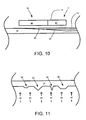
- FIG. 11 is a cross-sectional view of heating a sheet.
- smoothing of a sheet 13 may occur using, for example, a heater 50 or the heat from the melt 10 that melts the sheet 13.
- the local absorbed heat is proportional to the local surface area of the sheet 13, thereby preferentially melting protuberances, dendrites, or other irregularities 92 that form on the surface of the sheet 13.
- the heat flux 93 which may be from the melt 10 or radiation, melts the protuberances, dendrites, or other irregularities 92 prior to the rest of the sheet 13.
- thinning the sheet 13 will form a smoother sheet 13 with smaller or no protuberances, dendrites, or other irregularities 92.
- the uniformity of the surface of the sheet 13 may be relative to the size of the protuberances, dendrites, or other irregularities 92.
Claims (19)
- Procédé de formation d'une feuille (13) comprenant :le refroidissement d'une masse fondue (10) d'un matériau ;la formation d'une feuille (13) dudit matériau dans ladite masse fondue (10), ladite feuille (13) ayant une première épaisseur ;l'amincissement de ladite feuille (13) de ladite première épaisseur à une seconde épaisseur dans ladite masse fondue (10), ladite seconde épaisseur étant plus fine que ladite première épaisseur ; etla séparation de ladite feuille (13) de ladite masse fondue (10) après ledit amincissement.
- Procédé selon la revendication 1, dans lequel ladite matière fondue (10) est choisie dans le groupe constitué par le silicium, le silicium et le germanium, le gallium et le nitrure de gallium.
- Procédé selon la revendication 1, dans lequel ledit amincissement se produit à une vitesse d'au moins 1 µm/s.
- Procédé selon la revendication 1, comprenant en outre un second amincissement après ladite séparation en utilisant un élément chauffant radiatif (50).
- Procédé selon la revendication 1, dans lequel ladite séparation comprend l'utilisation d'un déversoir (12).
- Procédé selon la revendication 1, dans lequel ladite première épaisseur est de 200 µm et ladite seconde épaisseur est de 100 µm.
- Procédé selon la revendication 1, comprenant en outre le polissage d'une surface de ladite feuille (13) par ledit amincissement.
- Procédé selon la revendication 1, comprenant en outre le contrôle de ladite seconde épaisseur en modifiant un paramètre dudit amincissement.
- Appareil (21) pour former une feuille comprenant :un récipient (16) définissant un canal (17) configuré pour contenir une masse fondue (10) d'un matériau ;une plaque de refroidissement (14) située à proximité de ladite masse fondue (10), ladite plaque de refroidissement (14) étant configurée pour former une feuille (13) dudit matériau sur ladite masse fondue (10) ; etun élément chauffant radiatif (50) situé à une certaine distance dudit récipient (16) en aval d'une région où ladite feuille est séparée de ladite masse fondue (10).
- Appareil (21) selon la revendication 9, dans lequel ladite masse fondue (10) est choisie dans le groupe constitué par le silicium, le silicium et le germanium, le gallium et le nitrure de gallium.
- Appareil (21) selon la revendication 9, comprenant en outre un déversoir (12) situé dans ledit canal (17), ledit déversoir (12) étant situé dans ladite masse fondue (10) et configuré pour séparer ladite feuille (13) de ladite masse fondue (10), dans lequel ladite masse fondue (10) s'écoule séparément de ladite feuille (13).
- Procédé de formation d'une feuille (13) comprenant :le refroidissement d'une masse fondue (10) d'un matériau dans une première étape, ledit refroidissement dans ladite première étape possédant un premier paramètre ;la formation d'une première couche (90) d'une feuille (13) dudit matériau dans ladite masse fondue (10), ladite première couche (90) de ladite feuille (13) ayant une première épaisseur et une première concentration en soluté ;le refroidissement de ladite masse fondue (10) dans une seconde étape, ledit refroidissement dans ladite seconde étape possédant un second paramètre différent dudit premier paramètre ;l'augmentation de ladite feuille (13) d'une première épaisseur à une seconde épaisseur et la formation d'une seconde couche (91) de ladite feuille (13), ladite seconde couche (91) entre ladite première épaisseur et ladite seconde épaisseur ayant une seconde concentration en soluté supérieure à ladite première concentration en soluté ; etl'amincissement de ladite feuille (13) de ladite seconde épaisseur à ladite première épaisseur.
- Procédé selon la revendication 12, dans lequel ladite masse fondue (10) est choisie dans le groupe constitué par le silicium, le silicium et le germanium, le gallium et le nitrure de gallium.
- Procédé selon la revendication 12, dans lequel ladite première épaisseur est comprise entre 50 µm et 100 µm et ladite seconde épaisseur est comprise entre 150 µm et 200 µm.
- Procédé selon la revendication 12, comprenant en outre la réduction de la concentration en soluté dans ladite masse fondue par ladite augmentation et ledit amincissement.
- Procédé selon la revendication 15, dans lequel une masse fondue résiduaire provenant dudit amincissement est recueillie et séparée de ladite masse fondue (10).
- Procédé selon la revendication 15, dans lequel une masse fondue résiduaire provenant dudit amincissement est recueillie, puis purifiée et recyclée.
- Procédé selon la revendication 12, dans lequel ledit amincissement se produit après ladite formation et ladite augmentation en utilisant un élément chauffant radiatif (50).
- Procédé selon la revendication 12, dans lequel ledit premier paramètre et ledit second paramètre sont choisis dans le groupe constitué par une longueur et une température.
Applications Claiming Priority (3)
| Application Number | Priority Date | Filing Date | Title |
|---|---|---|---|
| US8928908P | 2008-08-15 | 2008-08-15 | |
| US12/539,125 US8475591B2 (en) | 2008-08-15 | 2009-08-11 | Method of controlling a thickness of a sheet formed from a melt |
| PCT/US2009/053588 WO2010019695A2 (fr) | 2008-08-15 | 2009-08-12 | Contrôle de l'épaisseur d'une feuille |
Publications (3)
| Publication Number | Publication Date |
|---|---|
| EP2319089A2 EP2319089A2 (fr) | 2011-05-11 |
| EP2319089A4 EP2319089A4 (fr) | 2011-10-26 |
| EP2319089B1 true EP2319089B1 (fr) | 2012-12-12 |
Family
ID=41669653
Family Applications (1)
| Application Number | Title | Priority Date | Filing Date |
|---|---|---|---|
| EP09807242A Active EP2319089B1 (fr) | 2008-08-15 | 2009-08-12 | Procédé et dispositif pour fabriquer une feuille à partir d'un bain fondu |
Country Status (7)
| Country | Link |
|---|---|
| US (1) | US8475591B2 (fr) |
| EP (1) | EP2319089B1 (fr) |
| JP (1) | JP5733830B2 (fr) |
| KR (1) | KR101681658B1 (fr) |
| CN (1) | CN102150283B (fr) |
| TW (1) | TWI463043B (fr) |
| WO (1) | WO2010019695A2 (fr) |
Families Citing this family (13)
| Publication number | Priority date | Publication date | Assignee | Title |
|---|---|---|---|---|
| US7955433B2 (en) * | 2007-07-26 | 2011-06-07 | Calisolar, Inc. | Method and system for forming a silicon ingot using a low-grade silicon feedstock |
| US7855087B2 (en) * | 2008-03-14 | 2010-12-21 | Varian Semiconductor Equipment Associates, Inc. | Floating sheet production apparatus and method |
| US9050652B2 (en) * | 2008-11-14 | 2015-06-09 | Carnegie Mellon University | Methods for casting by a float process and associated apparatuses |
| US8685162B2 (en) * | 2010-05-06 | 2014-04-01 | Varian Semiconductor Equipment Associates, Inc. | Removing a sheet from the surface of a melt using gas jets |
| US9057146B2 (en) * | 2010-08-24 | 2015-06-16 | Varian Semiconductor Equipment Associates, Inc. | Eddy current thickness measurement apparatus |
| US9970125B2 (en) * | 2012-02-17 | 2018-05-15 | Varian Semiconductor Equipment Associates, Inc. | Method for achieving sustained anisotropic crystal growth on the surface of a silicon melt |
| US20130213296A1 (en) * | 2012-02-17 | 2013-08-22 | Varian Semiconductor Equipment Associates, Inc. | Method for achieving sustained anisotropic crystal growth on the surface of a melt |
| EP3194850B1 (fr) | 2014-09-09 | 2019-12-11 | Siemens Aktiengesellschaft | Amortisseur acoustique pour chambre de combustion de turbine à gaz |
| US9556051B2 (en) | 2014-09-22 | 2017-01-31 | Corning Incorporated | Methods for controlling the thickness wedge in a glass ribbon |
| US10030317B2 (en) | 2014-10-17 | 2018-07-24 | Varian Semiconductor Equipment Associates, Inc. | Apparatus and method for controlling thickness of a crystalline sheet grown on a melt |
| TW201940875A (zh) * | 2014-10-17 | 2019-10-16 | 美商瓦里安半導體設備公司 | 薄片形成設備、用於測量熔體表面的薄片的厚度的系統及用於在薄片形成設備中測定材料界面的位置的方法 |
| US9574285B2 (en) | 2014-12-10 | 2017-02-21 | Varian Semiconductor Equipment Associates, Inc. | Apparatus and method for monitoring and controlling thickness of a crystalline layer |
| JP2022543358A (ja) * | 2019-08-09 | 2022-10-12 | リーディング エッジ イクウィップメント テクノロジーズ インコーポレイテッド | 酸素濃度の低い領域を有するリボンまたはウェハの製造 |
Family Cites Families (39)
| Publication number | Priority date | Publication date | Assignee | Title |
|---|---|---|---|---|
| US3430680A (en) * | 1966-06-16 | 1969-03-04 | George R Leghorn | Method of forming structural shapes from molten material by stream casting |
| US3681033A (en) * | 1969-01-31 | 1972-08-01 | Gen Motors Corp | Horizontal growth of crystal ribbons |
| US3607115A (en) * | 1969-10-29 | 1971-09-21 | Gen Motors Corp | Crystal pulling from molten melts including solute introduction means below the seed-melt interface |
| US3759671A (en) * | 1971-10-15 | 1973-09-18 | Gen Motors Corp | Horizontal growth of crystal ribbons |
| DE2633961C2 (de) * | 1975-07-28 | 1986-01-02 | Mitsubishi Kinzoku K.K. | Verfahren zum Ziehen eines dünnen Halbleiter-Einkristallbandes |
| JPS5261180A (en) * | 1975-11-14 | 1977-05-20 | Toyo Shirikon Kk | Horizontal growth of crystal ribbons |
| US4121965A (en) * | 1976-07-16 | 1978-10-24 | The United States Of America As Represented By The Administrator Of The National Aeronautics & Space Administration | Method of controlling defect orientation in silicon crystal ribbon growth |
| JPS5580798A (en) * | 1978-12-09 | 1980-06-18 | Agency Of Ind Science & Technol | Ribbon crystal growing method by lateral pulling |
| JPS5580797A (en) * | 1978-12-09 | 1980-06-18 | Agency Of Ind Science & Technol | Ribbon crystal growing method by lateral pulling accompanied by circulating melt convection |
| US4289571A (en) * | 1979-06-25 | 1981-09-15 | Energy Materials Corporation | Method and apparatus for producing crystalline ribbons |
| US4661200A (en) * | 1980-01-07 | 1987-04-28 | Sachs Emanuel M | String stabilized ribbon growth |
| US4417944A (en) * | 1980-07-07 | 1983-11-29 | Jewett David N | Controlled heat sink for crystal ribbon growth |
| DE3049376A1 (de) * | 1980-12-29 | 1982-07-29 | Heliotronic Forschungs- und Entwicklungsgesellschaft für Solarzellen-Grundstoffe mbH, 8263 Burghausen | Verfahren zur herstellung vertikaler pn-uebergaenge beim ziehen von siliciumscheiben aus einer siliciumschmelze |
| US4594229A (en) * | 1981-02-25 | 1986-06-10 | Emanuel M. Sachs | Apparatus for melt growth of crystalline semiconductor sheets |
| DE3132776A1 (de) * | 1981-08-19 | 1983-03-03 | Heliotronic Gmbh | Verfahren zur herstellung grob- bis einkristalliner folien aus halbleitermaterial |
| DE3338335A1 (de) * | 1983-10-21 | 1985-05-09 | Siemens AG, 1000 Berlin und 8000 München | Verfahren zum herstellen von grossflaechigen siliziumkristallkoerpern fuer solarzellen |
| US4599244A (en) * | 1984-07-11 | 1986-07-08 | Siemens Aktiengesellschaft | Method large-area silicon bodies |
| US4599132A (en) * | 1985-01-18 | 1986-07-08 | Energy Materials Corporation | Guidance system for low angle silicon ribbon growth |
| US4873063A (en) * | 1986-01-06 | 1989-10-10 | Bleil Carl E | Apparatus for zone regrowth of crystal ribbons |
| US5229083A (en) * | 1990-02-05 | 1993-07-20 | Bleil Carl E | Method and apparatus for crystal ribbon growth |
| US5055157A (en) * | 1990-02-05 | 1991-10-08 | Bleil Carl E | Method of crystal ribbon growth |
| US5069742A (en) * | 1990-02-05 | 1991-12-03 | Bleil Carl E | Method and apparatus for crystal ribbon growth |
| JPH0688106B2 (ja) | 1990-02-19 | 1994-11-09 | 株式会社オー・シー・シー | 帯状金属鋳塊の水平式連続鋳造法及びその装置 |
| JPH04104989A (ja) * | 1990-08-25 | 1992-04-07 | Sumitomo Electric Ind Ltd | 液相エピタキシャル成長方法および装置 |
| US5394825A (en) * | 1992-02-28 | 1995-03-07 | Crystal Systems, Inc. | Method and apparatus for growing shaped crystals |
| JP2642031B2 (ja) * | 1992-05-19 | 1997-08-20 | 住友電気工業株式会社 | 化合物半導体の液相エピタキシャル成長方法及び化合物半導体単結晶基板 |
| JPH06137814A (ja) * | 1992-10-27 | 1994-05-20 | Hitachi Ltd | 微小変位測定方法およびその装置 |
| JP2000182978A (ja) * | 1998-12-14 | 2000-06-30 | Sharp Corp | 液相エピタキシャル成長方法及び装置 |
| US6090199A (en) * | 1999-05-03 | 2000-07-18 | Evergreen Solar, Inc. | Continuous melt replenishment for crystal growth |
| JP4121697B2 (ja) * | 1999-12-27 | 2008-07-23 | シャープ株式会社 | 結晶シートの製造方法およびその製造装置 |
| US20060102078A1 (en) * | 2004-11-18 | 2006-05-18 | Intevac Inc. | Wafer fab |
| KR20060071957A (ko) | 2004-12-22 | 2006-06-27 | 주식회사 실트론 | 실리콘 기판의 제조 방법 |
| US20060213589A1 (en) * | 2005-03-23 | 2006-09-28 | Fuji Photo Film Co., Ltd. | Method of manufacturing a support for a lithographic printing plate |
| US8105434B2 (en) * | 2005-08-05 | 2012-01-31 | Faris Sadeg M | Si ribbon, SiO2 ribbon and ultra pure ribbons of other substances |
| EP1974076A2 (fr) * | 2006-01-20 | 2008-10-01 | BP Corporation North America Inc. | Procédés et appareils destinés à fabriquer du silicium coulé multicristallin géométrique et des corps de silicium coulé multicristallin géométrique pour des applications photovoltaïques |
| WO2007093082A1 (fr) | 2006-02-16 | 2007-08-23 | Yonggang Jin | Procédé de production de tranche de silicium utilisant la méthode du flottage et appareil correspondant |
| JP5433154B2 (ja) * | 2007-02-23 | 2014-03-05 | 株式会社半導体エネルギー研究所 | 半導体装置の作製方法 |
| US8064071B2 (en) * | 2008-03-14 | 2011-11-22 | Varian Semiconductor Equipment Associates, Inc. | Floating sheet measurement apparatus and method |
| US7855087B2 (en) * | 2008-03-14 | 2010-12-21 | Varian Semiconductor Equipment Associates, Inc. | Floating sheet production apparatus and method |
-
2009
- 2009-08-11 US US12/539,125 patent/US8475591B2/en active Active
- 2009-08-12 CN CN2009801355840A patent/CN102150283B/zh active Active
- 2009-08-12 WO PCT/US2009/053588 patent/WO2010019695A2/fr active Application Filing
- 2009-08-12 EP EP09807242A patent/EP2319089B1/fr active Active
- 2009-08-12 KR KR1020117005784A patent/KR101681658B1/ko active IP Right Grant
- 2009-08-12 JP JP2011523145A patent/JP5733830B2/ja active Active
- 2009-08-13 TW TW098127282A patent/TWI463043B/zh active
Also Published As
| Publication number | Publication date |
|---|---|
| WO2010019695A3 (fr) | 2010-04-15 |
| CN102150283B (zh) | 2013-06-05 |
| TW201012979A (en) | 2010-04-01 |
| EP2319089A2 (fr) | 2011-05-11 |
| EP2319089A4 (fr) | 2011-10-26 |
| JP5733830B2 (ja) | 2015-06-10 |
| WO2010019695A2 (fr) | 2010-02-18 |
| TWI463043B (zh) | 2014-12-01 |
| US8475591B2 (en) | 2013-07-02 |
| CN102150283A (zh) | 2011-08-10 |
| US20100038826A1 (en) | 2010-02-18 |
| JP2012500172A (ja) | 2012-01-05 |
| KR101681658B1 (ko) | 2016-12-01 |
| KR20110044784A (ko) | 2011-04-29 |
Similar Documents
| Publication | Publication Date | Title |
|---|---|---|
| EP2319089B1 (fr) | Procédé et dispositif pour fabriquer une feuille à partir d'un bain fondu | |
| US9112064B2 (en) | Floating sheet production apparatus and method | |
| US7816153B2 (en) | Method and apparatus for producing a dislocation-free crystalline sheet | |
| JP2012500172A5 (fr) | ||
| JP5961303B2 (ja) | ガスジェットを用いる融液の表面からのシートの取り出し | |
| US8226903B2 (en) | Removal of a sheet from a production apparatus | |
| EP2567001B1 (fr) | Procédé pour la production d'une feuille et son enlèvement de la surface d'un bain de fusion en utilisant l'élasticité et la flottabilité | |
| US20100080905A1 (en) | Solute stabilization of sheets formed from a melt |
Legal Events
| Date | Code | Title | Description |
|---|---|---|---|
| PUAI | Public reference made under article 153(3) epc to a published international application that has entered the european phase |
Free format text: ORIGINAL CODE: 0009012 |
|
| 17P | Request for examination filed |
Effective date: 20110214 |
|
| AK | Designated contracting states |
Kind code of ref document: A2 Designated state(s): AT BE BG CH CY CZ DE DK EE ES FI FR GB GR HR HU IE IS IT LI LT LU LV MC MK MT NL NO PL PT RO SE SI SK SM TR |
|
| AX | Request for extension of the european patent |
Extension state: AL BA RS |
|
| A4 | Supplementary search report drawn up and despatched |
Effective date: 20110926 |
|
| RIC1 | Information provided on ipc code assigned before grant |
Ipc: H01L 31/18 20060101ALI20110920BHEP Ipc: C30B 29/60 20060101ALI20110920BHEP Ipc: C30B 29/40 20060101ALI20110920BHEP Ipc: C30B 29/52 20060101ALI20110920BHEP Ipc: C30B 29/06 20060101AFI20110920BHEP Ipc: C30B 28/06 20060101ALI20110920BHEP Ipc: C30B 11/00 20060101ALI20110920BHEP |
|
| DAX | Request for extension of the european patent (deleted) | ||
| REG | Reference to a national code |
Ref country code: DE Ref legal event code: R079 Ref document number: 602009011960 Country of ref document: DE Free format text: PREVIOUS MAIN CLASS: H01L0031042000 Ipc: C30B0029060000 |
|
| RIC1 | Information provided on ipc code assigned before grant |
Ipc: H01L 31/18 20060101ALI20120605BHEP Ipc: C30B 28/06 20060101ALI20120605BHEP Ipc: C30B 29/52 20060101ALI20120605BHEP Ipc: C30B 29/06 20060101AFI20120605BHEP Ipc: C30B 29/40 20060101ALI20120605BHEP Ipc: C30B 29/60 20060101ALI20120605BHEP Ipc: C30B 11/00 20060101ALI20120605BHEP |
|
| GRAP | Despatch of communication of intention to grant a patent |
Free format text: ORIGINAL CODE: EPIDOSNIGR1 |
|
| GRAS | Grant fee paid |
Free format text: ORIGINAL CODE: EPIDOSNIGR3 |
|
| GRAA | (expected) grant |
Free format text: ORIGINAL CODE: 0009210 |
|
| AK | Designated contracting states |
Kind code of ref document: B1 Designated state(s): AT BE BG CH CY CZ DE DK EE ES FI FR GB GR HR HU IE IS IT LI LT LU LV MC MK MT NL NO PL PT RO SE SI SK SM TR |
|
| REG | Reference to a national code |
Ref country code: GB Ref legal event code: FG4D |
|
| REG | Reference to a national code |
Ref country code: CH Ref legal event code: EP |
|
| REG | Reference to a national code |
Ref country code: AT Ref legal event code: REF Ref document number: 588385 Country of ref document: AT Kind code of ref document: T Effective date: 20121215 |
|
| REG | Reference to a national code |
Ref country code: IE Ref legal event code: FG4D |
|
| REG | Reference to a national code |
Ref country code: DE Ref legal event code: R096 Ref document number: 602009011960 Country of ref document: DE Effective date: 20130207 |
|
| PG25 | Lapsed in a contracting state [announced via postgrant information from national office to epo] |
Ref country code: FI Free format text: LAPSE BECAUSE OF FAILURE TO SUBMIT A TRANSLATION OF THE DESCRIPTION OR TO PAY THE FEE WITHIN THE PRESCRIBED TIME-LIMIT Effective date: 20121212 Ref country code: LT Free format text: LAPSE BECAUSE OF FAILURE TO SUBMIT A TRANSLATION OF THE DESCRIPTION OR TO PAY THE FEE WITHIN THE PRESCRIBED TIME-LIMIT Effective date: 20121212 Ref country code: ES Free format text: LAPSE BECAUSE OF FAILURE TO SUBMIT A TRANSLATION OF THE DESCRIPTION OR TO PAY THE FEE WITHIN THE PRESCRIBED TIME-LIMIT Effective date: 20130323 Ref country code: SE Free format text: LAPSE BECAUSE OF FAILURE TO SUBMIT A TRANSLATION OF THE DESCRIPTION OR TO PAY THE FEE WITHIN THE PRESCRIBED TIME-LIMIT Effective date: 20121212 Ref country code: NO Free format text: LAPSE BECAUSE OF FAILURE TO SUBMIT A TRANSLATION OF THE DESCRIPTION OR TO PAY THE FEE WITHIN THE PRESCRIBED TIME-LIMIT Effective date: 20130312 |
|
| REG | Reference to a national code |
Ref country code: NL Ref legal event code: VDEP Effective date: 20121212 |
|
| REG | Reference to a national code |
Ref country code: AT Ref legal event code: MK05 Ref document number: 588385 Country of ref document: AT Kind code of ref document: T Effective date: 20121212 |
|
| REG | Reference to a national code |
Ref country code: LT Ref legal event code: MG4D |
|
| PG25 | Lapsed in a contracting state [announced via postgrant information from national office to epo] |
Ref country code: LV Free format text: LAPSE BECAUSE OF FAILURE TO SUBMIT A TRANSLATION OF THE DESCRIPTION OR TO PAY THE FEE WITHIN THE PRESCRIBED TIME-LIMIT Effective date: 20121212 Ref country code: SI Free format text: LAPSE BECAUSE OF FAILURE TO SUBMIT A TRANSLATION OF THE DESCRIPTION OR TO PAY THE FEE WITHIN THE PRESCRIBED TIME-LIMIT Effective date: 20121212 Ref country code: GR Free format text: LAPSE BECAUSE OF FAILURE TO SUBMIT A TRANSLATION OF THE DESCRIPTION OR TO PAY THE FEE WITHIN THE PRESCRIBED TIME-LIMIT Effective date: 20130313 |
|
| PG25 | Lapsed in a contracting state [announced via postgrant information from national office to epo] |
Ref country code: EE Free format text: LAPSE BECAUSE OF FAILURE TO SUBMIT A TRANSLATION OF THE DESCRIPTION OR TO PAY THE FEE WITHIN THE PRESCRIBED TIME-LIMIT Effective date: 20121212 Ref country code: CZ Free format text: LAPSE BECAUSE OF FAILURE TO SUBMIT A TRANSLATION OF THE DESCRIPTION OR TO PAY THE FEE WITHIN THE PRESCRIBED TIME-LIMIT Effective date: 20121212 Ref country code: AT Free format text: LAPSE BECAUSE OF FAILURE TO SUBMIT A TRANSLATION OF THE DESCRIPTION OR TO PAY THE FEE WITHIN THE PRESCRIBED TIME-LIMIT Effective date: 20121212 Ref country code: BG Free format text: LAPSE BECAUSE OF FAILURE TO SUBMIT A TRANSLATION OF THE DESCRIPTION OR TO PAY THE FEE WITHIN THE PRESCRIBED TIME-LIMIT Effective date: 20130312 Ref country code: IS Free format text: LAPSE BECAUSE OF FAILURE TO SUBMIT A TRANSLATION OF THE DESCRIPTION OR TO PAY THE FEE WITHIN THE PRESCRIBED TIME-LIMIT Effective date: 20130412 Ref country code: SK Free format text: LAPSE BECAUSE OF FAILURE TO SUBMIT A TRANSLATION OF THE DESCRIPTION OR TO PAY THE FEE WITHIN THE PRESCRIBED TIME-LIMIT Effective date: 20121212 Ref country code: BE Free format text: LAPSE BECAUSE OF FAILURE TO SUBMIT A TRANSLATION OF THE DESCRIPTION OR TO PAY THE FEE WITHIN THE PRESCRIBED TIME-LIMIT Effective date: 20121212 |
|
| PG25 | Lapsed in a contracting state [announced via postgrant information from national office to epo] |
Ref country code: PT Free format text: LAPSE BECAUSE OF FAILURE TO SUBMIT A TRANSLATION OF THE DESCRIPTION OR TO PAY THE FEE WITHIN THE PRESCRIBED TIME-LIMIT Effective date: 20130412 Ref country code: PL Free format text: LAPSE BECAUSE OF FAILURE TO SUBMIT A TRANSLATION OF THE DESCRIPTION OR TO PAY THE FEE WITHIN THE PRESCRIBED TIME-LIMIT Effective date: 20121212 Ref country code: RO Free format text: LAPSE BECAUSE OF FAILURE TO SUBMIT A TRANSLATION OF THE DESCRIPTION OR TO PAY THE FEE WITHIN THE PRESCRIBED TIME-LIMIT Effective date: 20121212 Ref country code: NL Free format text: LAPSE BECAUSE OF FAILURE TO SUBMIT A TRANSLATION OF THE DESCRIPTION OR TO PAY THE FEE WITHIN THE PRESCRIBED TIME-LIMIT Effective date: 20121212 |
|
| PLBE | No opposition filed within time limit |
Free format text: ORIGINAL CODE: 0009261 |
|
| STAA | Information on the status of an ep patent application or granted ep patent |
Free format text: STATUS: NO OPPOSITION FILED WITHIN TIME LIMIT |
|
| PG25 | Lapsed in a contracting state [announced via postgrant information from national office to epo] |
Ref country code: DK Free format text: LAPSE BECAUSE OF FAILURE TO SUBMIT A TRANSLATION OF THE DESCRIPTION OR TO PAY THE FEE WITHIN THE PRESCRIBED TIME-LIMIT Effective date: 20121212 |
|
| 26N | No opposition filed |
Effective date: 20130913 |
|
| PG25 | Lapsed in a contracting state [announced via postgrant information from national office to epo] |
Ref country code: CY Free format text: LAPSE BECAUSE OF FAILURE TO SUBMIT A TRANSLATION OF THE DESCRIPTION OR TO PAY THE FEE WITHIN THE PRESCRIBED TIME-LIMIT Effective date: 20121212 Ref country code: HR Free format text: LAPSE BECAUSE OF FAILURE TO SUBMIT A TRANSLATION OF THE DESCRIPTION OR TO PAY THE FEE WITHIN THE PRESCRIBED TIME-LIMIT Effective date: 20121212 |
|
| PG25 | Lapsed in a contracting state [announced via postgrant information from national office to epo] |
Ref country code: IT Free format text: LAPSE BECAUSE OF FAILURE TO SUBMIT A TRANSLATION OF THE DESCRIPTION OR TO PAY THE FEE WITHIN THE PRESCRIBED TIME-LIMIT Effective date: 20121212 |
|
| REG | Reference to a national code |
Ref country code: DE Ref legal event code: R097 Ref document number: 602009011960 Country of ref document: DE Effective date: 20130913 |
|
| REG | Reference to a national code |
Ref country code: CH Ref legal event code: PL |
|
| GBPC | Gb: european patent ceased through non-payment of renewal fee |
Effective date: 20130812 |
|
| PG25 | Lapsed in a contracting state [announced via postgrant information from national office to epo] |
Ref country code: CH Free format text: LAPSE BECAUSE OF NON-PAYMENT OF DUE FEES Effective date: 20130831 Ref country code: LI Free format text: LAPSE BECAUSE OF NON-PAYMENT OF DUE FEES Effective date: 20130831 Ref country code: MC Free format text: LAPSE BECAUSE OF FAILURE TO SUBMIT A TRANSLATION OF THE DESCRIPTION OR TO PAY THE FEE WITHIN THE PRESCRIBED TIME-LIMIT Effective date: 20121212 |
|
| REG | Reference to a national code |
Ref country code: IE Ref legal event code: MM4A |
|
| PG25 | Lapsed in a contracting state [announced via postgrant information from national office to epo] |
Ref country code: IE Free format text: LAPSE BECAUSE OF NON-PAYMENT OF DUE FEES Effective date: 20130812 Ref country code: GB Free format text: LAPSE BECAUSE OF NON-PAYMENT OF DUE FEES Effective date: 20130812 |
|
| PG25 | Lapsed in a contracting state [announced via postgrant information from national office to epo] |
Ref country code: SM Free format text: LAPSE BECAUSE OF FAILURE TO SUBMIT A TRANSLATION OF THE DESCRIPTION OR TO PAY THE FEE WITHIN THE PRESCRIBED TIME-LIMIT Effective date: 20121212 |
|
| REG | Reference to a national code |
Ref country code: FR Ref legal event code: PLFP Year of fee payment: 7 |
|
| PG25 | Lapsed in a contracting state [announced via postgrant information from national office to epo] |
Ref country code: TR Free format text: LAPSE BECAUSE OF FAILURE TO SUBMIT A TRANSLATION OF THE DESCRIPTION OR TO PAY THE FEE WITHIN THE PRESCRIBED TIME-LIMIT Effective date: 20121212 Ref country code: MT Free format text: LAPSE BECAUSE OF FAILURE TO SUBMIT A TRANSLATION OF THE DESCRIPTION OR TO PAY THE FEE WITHIN THE PRESCRIBED TIME-LIMIT Effective date: 20121212 |
|
| PG25 | Lapsed in a contracting state [announced via postgrant information from national office to epo] |
Ref country code: LU Free format text: LAPSE BECAUSE OF NON-PAYMENT OF DUE FEES Effective date: 20130812 Ref country code: MK Free format text: LAPSE BECAUSE OF FAILURE TO SUBMIT A TRANSLATION OF THE DESCRIPTION OR TO PAY THE FEE WITHIN THE PRESCRIBED TIME-LIMIT Effective date: 20121212 Ref country code: HU Free format text: LAPSE BECAUSE OF FAILURE TO SUBMIT A TRANSLATION OF THE DESCRIPTION OR TO PAY THE FEE WITHIN THE PRESCRIBED TIME-LIMIT; INVALID AB INITIO Effective date: 20090812 |
|
| REG | Reference to a national code |
Ref country code: FR Ref legal event code: PLFP Year of fee payment: 8 |
|
| REG | Reference to a national code |
Ref country code: FR Ref legal event code: PLFP Year of fee payment: 9 |
|
| REG | Reference to a national code |
Ref country code: FR Ref legal event code: PLFP Year of fee payment: 10 |
|
| PGFP | Annual fee paid to national office [announced via postgrant information from national office to epo] |
Ref country code: FR Payment date: 20190722 Year of fee payment: 11 |
|
| PG25 | Lapsed in a contracting state [announced via postgrant information from national office to epo] |
Ref country code: FR Free format text: LAPSE BECAUSE OF NON-PAYMENT OF DUE FEES Effective date: 20200831 |
|
| PGFP | Annual fee paid to national office [announced via postgrant information from national office to epo] |
Ref country code: DE Payment date: 20230828 Year of fee payment: 15 |