EP2318599B1 - Air admittance valve - Google Patents
Air admittance valve Download PDFInfo
- Publication number
- EP2318599B1 EP2318599B1 EP09786103.3A EP09786103A EP2318599B1 EP 2318599 B1 EP2318599 B1 EP 2318599B1 EP 09786103 A EP09786103 A EP 09786103A EP 2318599 B1 EP2318599 B1 EP 2318599B1
- Authority
- EP
- European Patent Office
- Prior art keywords
- main body
- lid
- sealing element
- valve
- air admittance
- Prior art date
- Legal status (The legal status is an assumption and is not a legal conclusion. Google has not performed a legal analysis and makes no representation as to the accuracy of the status listed.)
- Active
Links
Images


Classifications
-
- E—FIXED CONSTRUCTIONS
- E03—WATER SUPPLY; SEWERAGE
- E03C—DOMESTIC PLUMBING INSTALLATIONS FOR FRESH WATER OR WASTE WATER; SINKS
- E03C1/00—Domestic plumbing installations for fresh water or waste water; Sinks
- E03C1/12—Plumbing installations for waste water; Basins or fountains connected thereto; Sinks
- E03C1/122—Pipe-line systems for waste water in building
-
- E—FIXED CONSTRUCTIONS
- E03—WATER SUPPLY; SEWERAGE
- E03C—DOMESTIC PLUMBING INSTALLATIONS FOR FRESH WATER OR WASTE WATER; SINKS
- E03C1/00—Domestic plumbing installations for fresh water or waste water; Sinks
- E03C1/12—Plumbing installations for waste water; Basins or fountains connected thereto; Sinks
-
- E—FIXED CONSTRUCTIONS
- E03—WATER SUPPLY; SEWERAGE
- E03C—DOMESTIC PLUMBING INSTALLATIONS FOR FRESH WATER OR WASTE WATER; SINKS
- E03C1/00—Domestic plumbing installations for fresh water or waste water; Sinks
- E03C1/12—Plumbing installations for waste water; Basins or fountains connected thereto; Sinks
- E03C1/122—Pipe-line systems for waste water in building
- E03C1/1222—Arrangements of devices in domestic waste water pipe-line systems
- E03C1/1225—Arrangements of devices in domestic waste water pipe-line systems of air admittance valves
-
- F—MECHANICAL ENGINEERING; LIGHTING; HEATING; WEAPONS; BLASTING
- F16—ENGINEERING ELEMENTS AND UNITS; GENERAL MEASURES FOR PRODUCING AND MAINTAINING EFFECTIVE FUNCTIONING OF MACHINES OR INSTALLATIONS; THERMAL INSULATION IN GENERAL
- F16K—VALVES; TAPS; COCKS; ACTUATING-FLOATS; DEVICES FOR VENTING OR AERATING
- F16K15/00—Check valves
- F16K15/14—Check valves with flexible valve members
-
- F—MECHANICAL ENGINEERING; LIGHTING; HEATING; WEAPONS; BLASTING
- F16—ENGINEERING ELEMENTS AND UNITS; GENERAL MEASURES FOR PRODUCING AND MAINTAINING EFFECTIVE FUNCTIONING OF MACHINES OR INSTALLATIONS; THERMAL INSULATION IN GENERAL
- F16K—VALVES; TAPS; COCKS; ACTUATING-FLOATS; DEVICES FOR VENTING OR AERATING
- F16K24/00—Devices, e.g. valves, for venting or aerating enclosures
- F16K24/06—Devices, e.g. valves, for venting or aerating enclosures for aerating only
-
- Y—GENERAL TAGGING OF NEW TECHNOLOGICAL DEVELOPMENTS; GENERAL TAGGING OF CROSS-SECTIONAL TECHNOLOGIES SPANNING OVER SEVERAL SECTIONS OF THE IPC; TECHNICAL SUBJECTS COVERED BY FORMER USPC CROSS-REFERENCE ART COLLECTIONS [XRACs] AND DIGESTS
- Y10—TECHNICAL SUBJECTS COVERED BY FORMER USPC
- Y10T—TECHNICAL SUBJECTS COVERED BY FORMER US CLASSIFICATION
- Y10T137/00—Fluid handling
- Y10T137/7722—Line condition change responsive valves
- Y10T137/7837—Direct response valves [i.e., check valve type]
- Y10T137/7897—Vacuum relief type
-
- Y—GENERAL TAGGING OF NEW TECHNOLOGICAL DEVELOPMENTS; GENERAL TAGGING OF CROSS-SECTIONAL TECHNOLOGIES SPANNING OVER SEVERAL SECTIONS OF THE IPC; TECHNICAL SUBJECTS COVERED BY FORMER USPC CROSS-REFERENCE ART COLLECTIONS [XRACs] AND DIGESTS
- Y10—TECHNICAL SUBJECTS COVERED BY FORMER USPC
- Y10T—TECHNICAL SUBJECTS COVERED BY FORMER US CLASSIFICATION
- Y10T137/00—Fluid handling
- Y10T137/7722—Line condition change responsive valves
- Y10T137/7837—Direct response valves [i.e., check valve type]
- Y10T137/7904—Reciprocating valves
- Y10T137/7908—Weight biased
- Y10T137/7909—Valve body is the weight
- Y10T137/7913—Guided head
- Y10T137/7915—Guide stem
- Y10T137/7919—Guide and seat integral unit
-
- Y—GENERAL TAGGING OF NEW TECHNOLOGICAL DEVELOPMENTS; GENERAL TAGGING OF CROSS-SECTIONAL TECHNOLOGIES SPANNING OVER SEVERAL SECTIONS OF THE IPC; TECHNICAL SUBJECTS COVERED BY FORMER USPC CROSS-REFERENCE ART COLLECTIONS [XRACs] AND DIGESTS
- Y10—TECHNICAL SUBJECTS COVERED BY FORMER USPC
- Y10T—TECHNICAL SUBJECTS COVERED BY FORMER US CLASSIFICATION
- Y10T137/00—Fluid handling
- Y10T137/7722—Line condition change responsive valves
- Y10T137/7837—Direct response valves [i.e., check valve type]
- Y10T137/7904—Reciprocating valves
- Y10T137/7908—Weight biased
- Y10T137/7909—Valve body is the weight
- Y10T137/7913—Guided head
- Y10T137/7915—Guide stem
- Y10T137/792—Guide and closure integral unit
Definitions
- the present invention relates to air ventilation devices for use in pipe systems, and, more particularly, to air admittance valves used to vent pipe systems to the ambient environment.
- Air admittance valves are used in plumbing systems as an alternative to vent systems that require venting through a complicated pipe system and/or rooftop vent system.
- Air admittance valves are one-way mechanical valves that may be located in a ventilated space to alleviate a need to connect to a central vertical vent (or to provide a separate vertical vent) that passes through the roof of a structure.
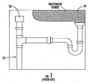
- FIG. 1 shows a typical application of an air admittance valve.
- Air admittance valves are normally closed, but open during a negative pressure condition, such as when wastewater is released. This allows air to enter the plumbing system and facilitate drainage. Once the flow of the wastewater ceases, the valve closes and remains closed until another negative pressure condition occurs. In such a manner, odors are prevented from escaping from the vent system.
- air admittance valves rely on gravity to close the valve once a negative pressure condition ceases.
- Such air admittance valves usually include sealing members that are constructed of multiple components.
- a rigid plate or frame structure is used to carry a thin flexible sealing member to and from closed and open positions.
- the thin flexible sealing member is bonded, stretched across, or otherwise fixed to the rigid frame structure.
- An example of such a design is described in U.S. Patent No. 4,535,807 .
- any detachment of the sealing member from the rigid frame structure is likely to result in inferior, and in some situations, failed performance of the air admittance valve.
- the ability of the sealing member to perform the sealing function is dictated by the accuracy of the dimensions of the frame structure. For instance, frame structures that have certain discontinuities, uneven surfaces, or other dimensional aberrations may not allow the sealing members to seal the valve in the closed position.
- the improved air admittance valve should be simpler and less expensive to manufacture, and should also provide enhanced performance with respect to the valve known from JP H11 325 289 , which provides a sealing member without a separate frame member.
- the present invention addresses the above needs and achieves other advantages by providing an air admittance valve configured when subjecte to a negative pressure condition to vent a pipe system to an ambient environment according to claim 1.
- the sealing member may further comprise a middle rib disposed between the inner and outer ribs.
- the lid may further comprise a top portion, and a side portion extending approximately perpendicularly from an outer perimeter of the top portion of the lid, the top and side portions of the lid each defining inner and outer surfaces such that the inner surfaces of the lid define a second chamber.
- the main body may further comprise an approximately cylindrically-shaped main body wall defining an inner surface and an outer surface, the main body further defining an internal communication element that extends inwardly from the inner surface of the main body wall, and wherein the internal communication element comprises a plurality of openings allowing communication therethrough between the first chamber and the second chamber.
- the one or more guiding elements may comprise a plurality of guiding elements that extend from the inner surface of the top portion of the lid.
- the plurality of guiding elements may comprise a plurality of triangularly-shaped ribs extending substantially downward from the inner surface of the top portion of the lid, the plurality of ribs defining a plurality of guiding edges and wherein the ribs are disposed radially about an imaginary center point.
- the main body may further comprise an approximately cylindrically-shaped main body wall defining an inner surface and an outer surface, wherein one end of the main body wall defines the inner valve seat, and wherein the main body further defines an external communication element that extends outwardly and at an angle from the outer surface of the main body wall such that an end of the external communication element defines the outer valve seat, wherein a third chamber is defined between the outer surface of the main body wall and the external communication element, and wherein the external communication element comprises a plurality of openings allowing communication therethrough between the third chamber and the ambient environment.
- a plurality of support walls may be disposed within the third chamber.
- the one or more guiding elements may comprise a plurality of guiding elements that extend from the internal communication element of the main body.
- the plurality of guiding elements may comprise a plurality of triangularly-shaped ribs extending from the internal communication element of the main body, and wherein the ribs may be disposed radially about an imaginary center point.
- the air admittance valve comprises a main body made of a rigid material, a flexible ring-shaped sealing member, and a lid made of a rigid material.
- the main body has top and bottom portions and is configured to sealingly attach to the pipe system proximate the bottom portion and a main body chamber configured to
- the main body also comprises an approximately cylindrically-shaped main body wall defining an inner surface and an outer surface, wherein one end of the main body wall defines an inner valve seat, and wherein the main body further defines an internal communication element and an external communication element, the internal communication element extending inwardly from the inner surface of the main body wall and comprising a plurality of openings allowing communication therethrough between the main body chamber and a lid chamber, the external communication element extending outwardly and at an angle from the outer surface of the main body wall such that an end of the external communication element defines an outer valve seat.
- An external communication chamber is defined between the outer surface of the main body wall and the external communication element, and the external communication element comprises a plurality of openings allowing communication therethrough between the external communication chamber and the ambient environment.
- a vent opening is defined between the inner and outer valves seats that is configured to provide communication between the external communication chamber and the lid chamber.
- the flexible ring-shaped sealing element is configured to move between a closed position and an open position, and the sealing element defines an outer perimeter surface, an inner perimeter surface, and opposite top and bottom surfaces extending between the outer and inner perimeter surfaces.
- the lid is made of a rigid material and is configured to sealingly attach to the main body proximate the top portion of the main body, the lid comprising a top portion, and a side portion extending approximately perpendicularly from an outer perimeter of the top portion, the top and side portions each defining inner and outer surfaces such that the inner surfaces define the lid chamber.
- the lid further comprises a plurality of triangularly-shaped ribs extending downward from the inner surface of the top portion of the lid and disposed radially about an imaginary center point such that the plurality of ribs define a plurality of guiding edges configured to guide the sealing element via the inner perimeter surface of the sealing element to and from the closed position, in which the bottom surface of the sealing element rests against the inner and outer valve seats of the main body thus blocking communication through the vent opening, and the open position, in which the sealing element rises off of the inner and outer valve seats such that the main body chamber communicates with the ambient environment through the vent opening, the lid chamber, and the external communication chamber.
- FIG.1 shows a common application of an air admittance valve in accordance with the prior art.
- an air admittance valve 20 communicates with a plumbing system 22 to vent the plumbing system upon the discharge of wastewater, such as from a wastewater source 24.
- wastewater such as from a wastewater source 24.
- the air admittance valve 20 opens upon discharge of the wastewater, it is normally closed to prevent the escape of gases from the plumbing system.
- many prior art air admittance valves include a rigid plate or frame structure that is used to carry a thin flexible sealing member to and from closed and open positions.
- these multipart constructions are not only difficult and expensive to manufacture, but sometimes result in poor performance due to inconsistencies in the frame structures.
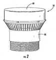
- FIG. 2 shows a perspective view of an assembled air admittance valve 50 in accordance with an exemplary embodiment of the present invention
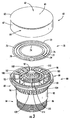
- FIG. 3 shows an exploded perspective view of the air admittance valve 50 in accordance with an exemplary embodiment of the present invention.
- the air admittance valve 50 according to various embodiments of the present invention includes a lid 60, a flexible sealing element 70 (not visible in FIG. 2 ) , and a main body 80. Referring to FIG.
- the lid 60 is made of a rigid thermoplastic material, such as, for example, polyvinyl chloride (PVC) or acrylonitrile butadiene styrene (ABS), and comprises a top portion 62 having an outer perimeter 63, and a side portion 64 that extends approximately perpendicularly from the outer perimeter 63 of the top portion 62.
- the top portion 62 includes an outer surface 65 and an inner surface 66 (inner surface 66 is visible in FIG. 4 ).
- the side portion 64 includes an outer surface 67 and an inner surface 68 (inner surface 68 is visible in FIG. 4 ).
- the lid may be constructed of any rigid material.
- a lid chamber 69 is defined by the inner surfaces 66, 68 of the lid 60 (lid chamber 69 is visible in FIG. 4 ).
- the lid 60 has a substantially circular top profile, which is designed to sealingly attach to the main body 80.
- the lid 60 and/or the main body 80 may have various other configurations and are not limited to the shapes and configurations shown in the figures.
- the lid 60 is constructed of a rigid material, and is attached to the main body 80 through the use of a sonic weld. In other embodiments however, the lid 60 may be secured to the main body 80 in any other manner designed to sealingly attach the lid 60 to the main body 80, including, but not limited to, other mechanical and/or chemical attachment methods.
- the sealing element 70 of the depicted embodiment is a ring-shaped seal constructed of a flexible material.
- the sealing element 70 could have a variety of shapes, including, for example, oblog, hourglass, and elliptical shapes.
- sealing element 70 comprises an outer perimeter surface 72, an inner perimeter surface 74, a top surface 76, and a bottom surface 78.
- the top and bottom surfaces 76, 78 are configured opposite of each other and extend between the outer perimeter surface 72 and the inner perimeter surface 74.
- the bottom surface 78 of the sealing member 70 defines a substantially planar surface in order to provide a seal for the air admittance valve 50.
- the top surface 76 of the sealing element 70 includes an outer rib 75, a middle rib 77, and an inner rib 79, wherein the ribs 75, 77, and 79 are substantially concentric about the center of the sealing element 70.
- the inner and outer ribs 75, 79 provide support for the sealing element in an area proximate the valve seats.
- the sealing member 70 is a unitary element constructed of a silicone material, however in other embodiments, various other configurations and materials are possible.
- the main body 80 of the air admittance valve 50 includes a top portion 82 and a bottom portion 84.
- the bottom portion 84 has a substantially cylindrical shape and includes a threaded section 86 proximate a distal end of the bottom portion 84.
- the threaded section 86 of the bottom portion 84 is defined in an outer surface of the bottom portion 84 so that the air admittance valve 50 may be affixed to an internally threaded end of an existing pipe system.
- the threaded section 86 could be defined by an inner surface of the bottom portion 84, or, in still other embodiments, other methods of attaching the air admittance valve 50 to the pipe system are possible.
- the cylindrical shape of the bottom portion 84 allows the depicted embodiment to interface with existing pipe systems, which often comprise substantially cylindrical pipes.
- the main body 80 of the air admittance valve 50 comprises an approximately cylindrically shaped main body wall 88 (seen more clearly in FIGS. 5 and 6 ) that defines an inner surface 90 and an outer surface 92.
- a main body chamber 93 (seen more clearly in FIGS. 5 and 6 ) is defined by the inner surface of the main body wall 88.
- the main body chamber 93 is configured to communicate with the attached pipe system.
- the main body 80 of the air admittance valve 50 is made of a rigid thermoplastic material, such as, for example, polyvinyl chloride (PVC) or acrylonitrile butadiene styrene (ABS). It should be noted that other embodiments, the main body 80 may be made of any rigid material. In some embodiments, such as the depicted embodiment, the material of the main body 80 may be chosen to complement the material of the lid 60. However, in other embodiments, the lid 50 and the main body 80 may be constructed of dissimilar materials.
- PVC polyvinyl chloride
- ABS acrylonitrile butadiene styrene
- the top end of the main body wall 88 defines a substantially circular surface having a rounded edge, thus defining an inner valve seat 95 of the air admittance valve 50.
- the main body wall 88 has a generally cylindrical shape, it necks inward between the bottom portion 84 and the top portion 82. In other embodiments, however, the main body wall 88 may have other configurations.
- the inner valve seat 95 of the depicted embodiment has a rounded profile, in other embodiments it could have various profiles configured to provide a seal with the sealing element 70.
- the top portion 82 of the air admittance valve 50 includes an external communication element 96 and an internal communication element 98.
- the external communication element 96 extends outwardly and upwardly at an angle from the outer surface 92 of the main body wall 88, and defines an external communication chamber 97 between the outer surface 92 and the external communication element 96.
- the end portion 99 of the external communication element 96 also defines an outer peripheral edge 101 upon which the lid 60 is attached.
- An end portion 99 of the external communication element 96 defines a substantially circular ring having a rounded edge, which defines an outer valve seat 100.
- the inner and outer valves seats 95, 100 are defined by the main body 80.
- the inner and outer valve seats may be defined by various other components, and in some embodiments the inner valve seat may be defined by one component and the outer valve seat may be defined by another component.
- the inner valve seat may be defined by the main body and the outer valve seat may be defined by the lid.
- the outer valve seat 100 of the depicted embodiment has a rounded profile, in other embodiments it could have various profiles configured to provide a seal with the sealing element 70. Additionally, in still other embodiments, the inner valve seat 95 and the outer valve seat 100 could have different profiles.
- the inner and outer valve seats 95, 100 are substantially concentric about the center of the main body wall 88, substantially co-planer with each other, and there is a vent opening 102 located between the valve seats 95,100.
- the vent opening 102 between the inner and outer valve seats 95, 100 is configured to allow venting through the vent opening 102, i.e., air can flow between the lid chamber 69 and the external communication chamber 97 via the vent opening 102.
- the external communication chamber 97 also includes a plurality of support elements 103 that extend between the outer surface 92 of the main body wall 88 and the external communication element 96.
- the plurality of support elements 103 are configured to prevent the sealing element 70 from becoming lodged in the external communication chamber 97, thus the plurality of support elements 103 are configured to provide support for the sealing element 70 should the sealing element tend to be drawn into the external communication chamber 97 through the vent opening 102 between the valve seats 95, 100. It should be noted that the plurality of support elements 103 are configured so as not to interfere with the ability of the valve 50 to allow communication of air through the vent opening 102 between the inner and outer valve seats 95, 100. Thus, in the depicted embodiment, a plurality of open areas 107 are defined between the plurality of support elements 103.
- the external communication element 96 is comprised of a plurality of projections 104 that extend between the outer surface 92 of the main body wall 88 and the end portion 99. As shown in the figure, the plurality of projections 104 define a plurality of openings 109 therebetween, such that the external communication element 96 allows communication of air between the ambient environment and the external communication chamber 97 through the openings 109. As will be described in more detail below, when the air admittance valve 50 is in an open position, air enters the air admittance valve 50 through the external communication element 96. As a result, the plurality of projections 104 act to protect the inside of the valve 50 from any debris or other materials that may tend to be carried by the air flow.
- an external communication element 96 may have other configurations, including smaller openings, larger openings, or combinations thereof.
- the external communication element 96 may have various other configurations, and in some embodiments, there need not be an external communication element 96.
- the main body 80 also defines an internal communication element 98 that extends inwardly and upwardly from the inner surface 90 of the main body wall 88 proximate the top end 94.
- the internal communication element 98 includes a mesh surface 110 ( FIG. 3 ) that extends to a top surface 112.
- the mesh surface 110 defines a plurality of openings 114, such that the internal communication element 98 allows communication of air through the openings 114.
- the mesh surface 110 acts to protect the inside of the valve 50 from any debris or other materials that may tend to be carried by the air flow, which may include various debris from the pipe system. It should be noted, however, in other embodiments of the present invention, other configurations of the internal communication element 98 are possible.
- any openings of the internal communication element 98 may have other configurations, including smaller openings, larger openings, or combinations thereof.
- the internal communication element 98 may have a various other configurations, and in some embodiments, there need not be an internal communication element.
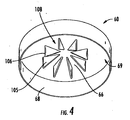
- FIG. 4 shows the underside of the lid 60.
- one or more guiding elements may extend from the lid 60.
- a plurality of guiding elements 105 extend from the inner surface 66 of the top portion 62 of the lid 60 into the lid chamber 69.
- a single guiding element may extend from the lid 60, such as, for example, a cylindrical element.
- the plurality of guiding elements 105 define a plurality of guiding surfaces 106 that extend downward from the inner surface 66 of the top portion 62.
- the plurality of guiding surfaces 106 are configured to guide the sealing member 70 by the inner perimeter surface 74 of the sealing member 70 to guide it as it moves between a closed position ( FIG . 5 ) and an open position ( FIG. 6 ).
- the plurality of guiding elements 105 comprises a plurality of substantially triangularly-shaped ribs that are radially disposed about an imaginary center point of the lid 60, and which define a plurality of open areas 108 therebetween such that air may be communicated within the lid chamber 69.
- the shape of the guiding elements 105 is configured to complement the shape of the internal communication element 98, however, in other embodiments the plurality of guiding elements 105 may have any configuration that provides a plurality of guiding surfaces 106 for guiding the sealing member 70 by the inner perimeter surface 74 of the sealing member 70 and that allow the lid 60 to be sealingly attached to the main body 80.
- one or more guiding elements may be part of the main body 80 and may extend up from the main body 80, rather than down from the lid 60.
- An example of an embodiment showing a plurality of guiding elements 105 extending from the main body 80 is depicted in FIG. 7 .
- one or more guiding elements 105 may be part of the lid 60 and one or more guiding elements 105 may be part of the main body 80.
- An example of such an embodiment is depicted in FIG. 8 .
- the plurality of guiding elements 105 includes a plurality of guiding surfaces 106 configured to guide the sealing element 70 by the inner perimeter surface 74 of the sealing element 70.
- FIG. 5 shows a cross-section view of the air admittance valve 50 in the closed position.
- the sealing element 70 rests via force of gravity on the inner and outer valve seats 95, 100 of the main body 80, thus covering the vent opening 102 between the inner and outer valve seats 95, 100.
- the sealing member 70 blocks communication through the vent opening 102 between the inner and outer valves seats 95,100.
- air communication between the pipe system and the ambient environment is blocked.
- the inner and outer ribs 75, 79 of the sealing element 70 may be configured to approximately line up with the inner and outer valve seats 95, 100 of the main body 80 so as to provide support via increased thickness in these areas, thus providing reinforcing support for the sealing element 70 in the areas of contact with the valve seats 95,100.
- the sealing member 70 is subjected to air pressure differentials that may tend to press the sealing member 70 downward into the external communication chamber 97.
- the middle rib 77 of the sealing element 70 is configured to be placed in an area between the inner and outer valve seats 95,100 and proximate the plurality of support elements 103 located in the external communication chamber 97 so as to provide support for the sealing member 70 should the sealing member 70 be pressed downward.
- the plurality of support elements 103 of the depicted embodiment tend to keep the sealing element 70 from becoming trapped in the external communication chamber, and the middle rib 75 provides reinforcing support for the sealing element 70 in an area of contact with the support elements 103.
- the plurality of support elements 103 do not extend up to the inner and outer valve seats 95, 100 so as not to interfere with the sealing of the valve seats 95,100.
- other support element designs are possible, and in still other embodiments there need not be any support elements in the external communication chamber 97.
- FIG. 6 shows a cross section view of the air admittance valve 50 in the open position.
- the open position is created by a negative pressure condition, which may be initiated when wastewater in the pipe system is released (such as, for example, by flushing a toilet or by draining a wastewater tub).
- the negative pressure condition causes the sealing element 70 to rise off of the inner and outer valve seats 95, 100, thus opening communication of air through the vent opening 102 between the inner and outer valve seats 95, 100.
- the sealing element 70 is guided into the lid chamber 69 via its inner perimeter surface 74 by the plurality of guiding surfaces 106 defined by the plurality of guiding elements 105.
- the sealing element 70 drops down from the lid chamber 69, again guided via its inner perimeter surface 74 by the plurality of guiding surfaces 106 defined by the plurality of guiding elements 105 and onto the inner and outer valve seats 95, 100, thus sealing the vent opening 102 between the valve seats 95, 100, and, closing the valve 50.
- the present invention improves on the prior art by providing an air admittance valve 50 having a sealing element 70 that is guided to and from open and closed positions via an inner perimeter surface 74 of the sealing element 70, and thus without the need for a separate guiding frame structure attached to the sealing member 70.
- the present invention provides a simpler air admittance valve design and that provides enhanced performance that is less expensive to manufacture.
Landscapes
- Engineering & Computer Science (AREA)
- General Engineering & Computer Science (AREA)
- Environmental & Geological Engineering (AREA)
- Health & Medical Sciences (AREA)
- Life Sciences & Earth Sciences (AREA)
- Hydrology & Water Resources (AREA)
- Public Health (AREA)
- Water Supply & Treatment (AREA)
- Structural Engineering (AREA)
- Mechanical Engineering (AREA)
- Self-Closing Valves And Venting Or Aerating Valves (AREA)
- Sink And Installation For Waste Water (AREA)
Description
- The present invention relates to air ventilation devices for use in pipe systems, and, more particularly, to air admittance valves used to vent pipe systems to the ambient environment.
- In general, air admittance valves are used in plumbing systems as an alternative to vent systems that require venting through a complicated pipe system and/or rooftop vent system. Air admittance valves are one-way mechanical valves that may be located in a ventilated space to alleviate a need to connect to a central vertical vent (or to provide a separate vertical vent) that passes through the roof of a structure.
FIG. 1 shows a typical application of an air admittance valve. Air admittance valves are normally closed, but open during a negative pressure condition, such as when wastewater is released. This allows air to enter the plumbing system and facilitate drainage. Once the flow of the wastewater ceases, the valve closes and remains closed until another negative pressure condition occurs. In such a manner, odors are prevented from escaping from the vent system. - Many air admittance valves rely on gravity to close the valve once a negative pressure condition ceases. Such air admittance valves usually include sealing members that are constructed of multiple components. Typically, a rigid plate or frame structure is used to carry a thin flexible sealing member to and from closed and open positions. In many instances the thin flexible sealing member is bonded, stretched across, or otherwise fixed to the rigid frame structure. An example of such a design is described in
U.S. Patent No. 4,535,807 . - These multipart constructions, however, are difficult and expensive to manufacture. Additionally, any detachment of the sealing member from the rigid frame structure is likely to result in inferior, and in some situations, failed performance of the air admittance valve. Furthermore, in many situations the ability of the sealing member to perform the sealing function is dictated by the accuracy of the dimensions of the frame structure. For instance, frame structures that have certain discontinuities, uneven surfaces, or other dimensional aberrations may not allow the sealing members to seal the valve in the closed position.
- There is a need, therefore, for an improved air admittance valve that is configured to vent pipe systems to the ambient environment. The improved air admittance valve should be simpler and less expensive to manufacture, and should also provide enhanced performance with respect to the valve known from
JP H11 325 289 - The present invention addresses the above needs and achieves other advantages by providing an air admittance valve configured when subjecte to a negative pressure condition to vent a pipe system to an ambient environment according to
claim 1. In embodiments, the sealing member may further comprise a middle rib disposed between the inner and outer ribs. - In some embodiments, the lid may further comprise a top portion, and a side portion extending approximately perpendicularly from an outer perimeter of the top portion of the lid, the top and side portions of the lid each defining inner and outer surfaces such that the inner surfaces of the lid define a second chamber. In some embodiments, the main body may further comprise an approximately cylindrically-shaped main body wall defining an inner surface and an outer surface, the main body further defining an internal communication element that extends inwardly from the inner surface of the main body wall, and wherein the internal communication element comprises a plurality of openings allowing communication therethrough between the first chamber and the second chamber. In some embodiments, the one or more guiding elements may comprise a plurality of guiding elements that extend from the inner surface of the top portion of the lid. In other embodiments, the plurality of guiding elements may comprise a plurality of triangularly-shaped ribs extending substantially downward from the inner surface of the top portion of the lid, the plurality of ribs defining a plurality of guiding edges and wherein the ribs are disposed radially about an imaginary center point.
- In some embodiments, the main body may further comprise an approximately cylindrically-shaped main body wall defining an inner surface and an outer surface, wherein one end of the main body wall defines the inner valve seat, and wherein the main body further defines an external communication element that extends outwardly and at an angle from the outer surface of the main body wall such that an end of the external communication element defines the outer valve seat, wherein a third chamber is defined between the outer surface of the main body wall and the external communication element, and wherein the external communication element comprises a plurality of openings allowing communication therethrough between the third chamber and the ambient environment. In some embodiments, a plurality of support walls may be disposed within the third chamber. In other embodiments, the one or more guiding elements may comprise a plurality of guiding elements that extend from the internal communication element of the main body. In other embodiments, the plurality of guiding elements may comprise a plurality of triangularly-shaped ribs extending from the internal communication element of the main body, and wherein the ribs may be disposed radially about an imaginary center point.
- In another not claimed embodiment, the air admittance valve comprises a main body made of a rigid material, a flexible ring-shaped sealing member, and a lid made of a rigid material. The main body has top and bottom portions and is configured to sealingly attach to the pipe system proximate the bottom portion and a main body chamber configured to The main body also comprises an approximately cylindrically-shaped main body wall defining an inner surface and an outer surface, wherein one end of the main body wall defines an inner valve seat, and wherein the main body further defines an internal communication element and an external communication element, the internal communication element extending inwardly from the inner surface of the main body wall and comprising a plurality of openings allowing communication therethrough between the main body chamber and a lid chamber, the external communication element extending outwardly and at an angle from the outer surface of the main body wall such that an end of the external communication element defines an outer valve seat. An external communication chamber is defined between the outer surface of the main body wall and the external communication element, and the external communication element comprises a plurality of openings allowing communication therethrough between the external communication chamber and the ambient environment. A vent opening is defined between the inner and outer valves seats that is configured to provide communication between the external communication chamber and the lid chamber. The flexible ring-shaped sealing element is configured to move between a closed position and an open position, and the sealing element defines an outer perimeter surface, an inner perimeter surface, and opposite top and bottom surfaces extending between the outer and inner perimeter surfaces. The lid is made of a rigid material and is configured to sealingly attach to the main body proximate the top portion of the main body, the lid comprising a top portion, and a side portion extending approximately perpendicularly from an outer perimeter of the top portion, the top and side portions each defining inner and outer surfaces such that the inner surfaces define the lid chamber. The lid further comprises a plurality of triangularly-shaped ribs extending downward from the inner surface of the top portion of the lid and disposed radially about an imaginary center point such that the plurality of ribs define a plurality of guiding edges configured to guide the sealing element via the inner perimeter surface of the sealing element to and from the closed position, in which the bottom surface of the sealing element rests against the inner and outer valve seats of the main body thus blocking communication through the vent opening, and the open position, in which the sealing element rises off of the inner and outer valve seats such that the main body chamber communicates with the ambient environment through the vent opening, the lid chamber, and the external communication chamber.
- Having thus described the invention in general terms, reference will now be made to the accompanying drawings, which are not necessarily drawn to scale, and wherein:
-
FIG. 1 shows a common application of an air admittance valve in accordance with the prior art; -
FIG. 2 is a perspective view of an assembled air admittance valve in accordance with an exemplary embodiment of the present invention; -
FIG. 3 is an exploded perspective view showing a lid, a sealing member, and a main body of an air admittance valve in accordance with an exemplary embodiment of the present invention; -
FIG. 4 is a perspective view of the underside of a lid of an air admittance valve in accordance with an exemplary embodiment of the present invention; -
FIG. 5 is a cross-section view of an assembled air admittance valve in a closed position in accordance with an exemplary embodiment of the present invention; -
FIG. 6 is a cross-section view of an assembled air admittance valve in an open position in accordance with an exemplary embodiment of the present invention; -
FIG. 7 is an exploded perspective view showing a sealing member, a main body, and the underside of a lid of an air admittance valve in accordance with a not claimed exemplary embodiment of the present invention; and -
FIG. 8 is an exploded perspective view showing a sealing member, a main body, and the underside of a lid of the air admittance valve in accordance with yet another exemplary embodiment of the present invention. - The present invention now will be described more fully hereinafter with reference to the accompanying drawings, in which some, but not all embodiments of the invention are shown. Indeed, the present invention may be embodied in many different forms and should not be construed as limited to the embodiments set forth herein; rather, these embodiments are provided so that this disclosure will satisfy applicable legal requirements. Like numbers refer to like elements throughout.
-
FIG.1 shows a common application of an air admittance valve in accordance with the prior art. As depicted in the figure, in a common application anair admittance valve 20 communicates with aplumbing system 22 to vent the plumbing system upon the discharge of wastewater, such as from awastewater source 24. Although theair admittance valve 20 opens upon discharge of the wastewater, it is normally closed to prevent the escape of gases from the plumbing system. As noted above, many prior art air admittance valves include a rigid plate or frame structure that is used to carry a thin flexible sealing member to and from closed and open positions. However, these multipart constructions are not only difficult and expensive to manufacture, but sometimes result in poor performance due to inconsistencies in the frame structures. -
FIG. 2 shows a perspective view of an assembledair admittance valve 50 in accordance with an exemplary embodiment of the present invention, andFIG. 3 shows an exploded perspective view of theair admittance valve 50 in accordance with an exemplary embodiment of the present invention. In general, theair admittance valve 50 according to various embodiments of the present invention includes alid 60, a flexible sealing element 70 (not visible inFIG. 2 ), and amain body 80. Referring toFIG. 3 , in the depicted embodiment, thelid 60 is made of a rigid thermoplastic material, such as, for example, polyvinyl chloride (PVC) or acrylonitrile butadiene styrene (ABS), and comprises atop portion 62 having anouter perimeter 63, and aside portion 64 that extends approximately perpendicularly from theouter perimeter 63 of thetop portion 62. Thetop portion 62 includes anouter surface 65 and an inner surface 66 (inner surface 66 is visible inFIG. 4 ). Likewise, theside portion 64 includes anouter surface 67 and an inner surface 68 (inner surface 68 is visible inFIG. 4 ). It should be noted that in other embodiments, the lid may be constructed of any rigid material. Additionally, other configurations of the lid are possible, including, for example, disk-like configurations that do not include side portions. In the depicted embodiment, alid chamber 69 is defined by theinner surfaces lid chamber 69 is visible inFIG. 4 ). As shown in the figure, thelid 60 has a substantially circular top profile, which is designed to sealingly attach to themain body 80. It should be noted that in other embodiments thelid 60 and/or themain body 80 may have various other configurations and are not limited to the shapes and configurations shown in the figures. In the depicted embodiment, thelid 60 is constructed of a rigid material, and is attached to themain body 80 through the use of a sonic weld. In other embodiments however, thelid 60 may be secured to themain body 80 in any other manner designed to sealingly attach thelid 60 to themain body 80, including, but not limited to, other mechanical and/or chemical attachment methods. - The sealing
element 70 of the depicted embodiment is a ring-shaped seal constructed of a flexible material. However, it should be noted that in other embodiments, the sealingelement 70 could have a variety of shapes, including, for example, oblog, hourglass, and elliptical shapes. In the depicted embodiment, sealingelement 70 comprises anouter perimeter surface 72, aninner perimeter surface 74, atop surface 76, and abottom surface 78. The top andbottom surfaces outer perimeter surface 72 and theinner perimeter surface 74. Although not visible inFIG. 3 , thebottom surface 78 of the sealingmember 70 defines a substantially planar surface in order to provide a seal for theair admittance valve 50. In the depicted embodiment, thetop surface 76 of the sealingelement 70 includes anouter rib 75, amiddle rib 77, and aninner rib 79, wherein theribs element 70. Although other embodiments of the present invention may not include ribs, in the depicted embodiment, the inner andouter ribs member 70 is a unitary element constructed of a silicone material, however in other embodiments, various other configurations and materials are possible. - Referring to
FIG. 3 , themain body 80 of theair admittance valve 50 includes atop portion 82 and abottom portion 84. In the depicted embodiment, thebottom portion 84 has a substantially cylindrical shape and includes a threadedsection 86 proximate a distal end of thebottom portion 84. In the depicted embodiment, the threadedsection 86 of thebottom portion 84 is defined in an outer surface of thebottom portion 84 so that theair admittance valve 50 may be affixed to an internally threaded end of an existing pipe system. In other embodiments, however, the threadedsection 86 could be defined by an inner surface of thebottom portion 84, or, in still other embodiments, other methods of attaching theair admittance valve 50 to the pipe system are possible. Although other physical configurations are possible, the cylindrical shape of thebottom portion 84 allows the depicted embodiment to interface with existing pipe systems, which often comprise substantially cylindrical pipes. - The
main body 80 of theair admittance valve 50 comprises an approximately cylindrically shaped main body wall 88 (seen more clearly inFIGS. 5 and6 ) that defines aninner surface 90 and anouter surface 92. A main body chamber 93 (seen more clearly inFIGS. 5 and6 ) is defined by the inner surface of themain body wall 88. Thus, in the depicted embodiment, when theair admittance valve 50 is attached to an existing pipe system, themain body chamber 93 is configured to communicate with the attached pipe system. In the depicted embodiment, themain body 80 of theair admittance valve 50 is made of a rigid thermoplastic material, such as, for example, polyvinyl chloride (PVC) or acrylonitrile butadiene styrene (ABS). It should be noted that other embodiments, themain body 80 may be made of any rigid material. In some embodiments, such as the depicted embodiment, the material of themain body 80 may be chosen to complement the material of thelid 60. However, in other embodiments, thelid 50 and themain body 80 may be constructed of dissimilar materials. - The top end of the
main body wall 88 defines a substantially circular surface having a rounded edge, thus defining aninner valve seat 95 of theair admittance valve 50. It should be noted that in the depicted embodiment, although themain body wall 88 has a generally cylindrical shape, it necks inward between thebottom portion 84 and thetop portion 82. In other embodiments, however, themain body wall 88 may have other configurations. Additionally, although theinner valve seat 95 of the depicted embodiment has a rounded profile, in other embodiments it could have various profiles configured to provide a seal with the sealingelement 70. - In the depicted embodiment, the
top portion 82 of theair admittance valve 50 includes anexternal communication element 96 and aninternal communication element 98. Theexternal communication element 96 extends outwardly and upwardly at an angle from theouter surface 92 of themain body wall 88, and defines anexternal communication chamber 97 between theouter surface 92 and theexternal communication element 96. Theend portion 99 of theexternal communication element 96 also defines an outerperipheral edge 101 upon which thelid 60 is attached. Anend portion 99 of theexternal communication element 96 defines a substantially circular ring having a rounded edge, which defines anouter valve seat 100. As such, in the depicted embodiment, the inner and outer valves seats 95, 100 are defined by themain body 80. However, in other embodiments the inner and outer valve seats may be defined by various other components, and in some embodiments the inner valve seat may be defined by one component and the outer valve seat may be defined by another component. For example, in one embodiment the inner valve seat may be defined by the main body and the outer valve seat may be defined by the lid. Also, although theouter valve seat 100 of the depicted embodiment has a rounded profile, in other embodiments it could have various profiles configured to provide a seal with the sealingelement 70. Additionally, in still other embodiments, theinner valve seat 95 and theouter valve seat 100 could have different profiles. - In the depicted embodiment, the inner and
outer valve seats main body wall 88, substantially co-planer with each other, and there is avent opening 102 located between the valve seats 95,100. As will be described in more detail below, when theair admittance valve 50 is in an open position, thevent opening 102 between the inner andouter valve seats vent opening 102, i.e., air can flow between thelid chamber 69 and theexternal communication chamber 97 via thevent opening 102. In the depicted embodiment, theexternal communication chamber 97 also includes a plurality ofsupport elements 103 that extend between theouter surface 92 of themain body wall 88 and theexternal communication element 96. As will be described in more detail below, in various embodiments, the plurality ofsupport elements 103 are configured to prevent the sealingelement 70 from becoming lodged in theexternal communication chamber 97, thus the plurality ofsupport elements 103 are configured to provide support for the sealingelement 70 should the sealing element tend to be drawn into theexternal communication chamber 97 through thevent opening 102 between the valve seats 95, 100. It should be noted that the plurality ofsupport elements 103 are configured so as not to interfere with the ability of thevalve 50 to allow communication of air through thevent opening 102 between the inner andouter valve seats open areas 107 are defined between the plurality ofsupport elements 103. - In the depicted embodiment, the
external communication element 96 is comprised of a plurality ofprojections 104 that extend between theouter surface 92 of themain body wall 88 and theend portion 99. As shown in the figure, the plurality ofprojections 104 define a plurality ofopenings 109 therebetween, such that theexternal communication element 96 allows communication of air between the ambient environment and theexternal communication chamber 97 through theopenings 109. As will be described in more detail below, when theair admittance valve 50 is in an open position, air enters theair admittance valve 50 through theexternal communication element 96. As a result, the plurality ofprojections 104 act to protect the inside of thevalve 50 from any debris or other materials that may tend to be carried by the air flow. It should be noted, however, in other embodiments of the present invention, other configurations of anexternal communication element 96 are possible. In such a manner, theopenings 109 of theexternal communication element 96 may have other configurations, including smaller openings, larger openings, or combinations thereof. Furthermore, in various embodiments, theexternal communication element 96 may have various other configurations, and in some embodiments, there need not be anexternal communication element 96. - As noted above, the
main body 80 also defines aninternal communication element 98 that extends inwardly and upwardly from theinner surface 90 of themain body wall 88 proximate the top end 94. In the depicted embodiment, theinternal communication element 98 includes a mesh surface 110 (FIG. 3 ) that extends to atop surface 112. Themesh surface 110 defines a plurality ofopenings 114, such that theinternal communication element 98 allows communication of air through theopenings 114. Themesh surface 110 acts to protect the inside of thevalve 50 from any debris or other materials that may tend to be carried by the air flow, which may include various debris from the pipe system. It should be noted, however, in other embodiments of the present invention, other configurations of theinternal communication element 98 are possible. In such a manner, any openings of theinternal communication element 98 may have other configurations, including smaller openings, larger openings, or combinations thereof. Furthermore, in various embodiments, theinternal communication element 98 may have a various other configurations, and in some embodiments, there need not be an internal communication element. -
FIG. 4 shows the underside of thelid 60. In various embodiments, one or more guiding elements may extend from thelid 60. In the depicted embodiment, a plurality of guidingelements 105 extend from theinner surface 66 of thetop portion 62 of thelid 60 into thelid chamber 69. However, in other embodiments a single guiding element may extend from thelid 60, such as, for example, a cylindrical element. In the depicted embodiment, the plurality of guidingelements 105 define a plurality of guidingsurfaces 106 that extend downward from theinner surface 66 of thetop portion 62. As will be described in more detail below, the plurality of guidingsurfaces 106 are configured to guide the sealingmember 70 by theinner perimeter surface 74 of the sealingmember 70 to guide it as it moves between a closed position (FIG. 5 ) and an open position (FIG. 6 ). In the depicted embodiment, the plurality of guidingelements 105 comprises a plurality of substantially triangularly-shaped ribs that are radially disposed about an imaginary center point of thelid 60, and which define a plurality ofopen areas 108 therebetween such that air may be communicated within thelid chamber 69. In the depicted embodiment, the shape of the guidingelements 105 is configured to complement the shape of theinternal communication element 98, however, in other embodiments the plurality of guidingelements 105 may have any configuration that provides a plurality of guidingsurfaces 106 for guiding the sealingmember 70 by theinner perimeter surface 74 of the sealingmember 70 and that allow thelid 60 to be sealingly attached to themain body 80. - In some embodiments, one or more guiding elements may be part of the
main body 80 and may extend up from themain body 80, rather than down from thelid 60. An example of an embodiment showing a plurality of guidingelements 105 extending from themain body 80 is depicted inFIG. 7 . In other embodiments, one ormore guiding elements 105 may be part of thelid 60 and one ormore guiding elements 105 may be part of themain body 80. An example of such an embodiment is depicted inFIG. 8 . In such a manner, the plurality of guidingelements 105 includes a plurality of guidingsurfaces 106 configured to guide the sealingelement 70 by theinner perimeter surface 74 of the sealingelement 70. -
FIG. 5 shows a cross-section view of theair admittance valve 50 in the closed position. As shown in the figure, in the closed position the sealingelement 70 rests via force of gravity on the inner andouter valve seats main body 80, thus covering thevent opening 102 between the inner andouter valve seats main body chamber 93 and the internal communication element 98), the sealingmember 70 blocks communication through thevent opening 102 between the inner and outer valves seats 95,100. Thus, air communication between the pipe system and the ambient environment is blocked. As shown in the figure, in some embodiments the inner andouter ribs element 70 may be configured to approximately line up with the inner andouter valve seats main body 80 so as to provide support via increased thickness in these areas, thus providing reinforcing support for the sealingelement 70 in the areas of contact with the valve seats 95,100. - Additionally, in some embodiments, there may be situations where the sealing
member 70 is subjected to air pressure differentials that may tend to press the sealingmember 70 downward into theexternal communication chamber 97. As also shown in the figure, in the depicted embodiment, themiddle rib 77 of the sealingelement 70 is configured to be placed in an area between the inner and outer valve seats 95,100 and proximate the plurality ofsupport elements 103 located in theexternal communication chamber 97 so as to provide support for the sealingmember 70 should the sealingmember 70 be pressed downward. As such, the plurality ofsupport elements 103 of the depicted embodiment tend to keep the sealingelement 70 from becoming trapped in the external communication chamber, and themiddle rib 75 provides reinforcing support for the sealingelement 70 in an area of contact with thesupport elements 103. It should be noted that, in the depicted embodiment, the plurality ofsupport elements 103 do not extend up to the inner andouter valve seats external communication chamber 97. -
FIG. 6 shows a cross section view of theair admittance valve 50 in the open position. The open position is created by a negative pressure condition, which may be initiated when wastewater in the pipe system is released (such as, for example, by flushing a toilet or by draining a wastewater tub). The negative pressure condition causes the sealingelement 70 to rise off of the inner andouter valve seats vent opening 102 between the inner andouter valve seats element 70 is guided into thelid chamber 69 via itsinner perimeter surface 74 by the plurality of guidingsurfaces 106 defined by the plurality of guidingelements 105. Once in the open position, communication of air through thevent opening 102 between the inner andouter valve seats openings 106 of theexternal communication element 96 into theexternal communication chamber 97, and from theexternal communication chamber 97 through thevent opening 102 between the inner andouter valve seats lid chamber 69, and from thelid chamber 69 through theopenings 114 of theinternal communication element 98 and into themain body chamber 93, which is in direct communication with the pipe system. When the negative pressure condition ceases, the sealingelement 70 drops down from thelid chamber 69, again guided via itsinner perimeter surface 74 by the plurality of guidingsurfaces 106 defined by the plurality of guidingelements 105 and onto the inner andouter valve seats vent opening 102 between the valve seats 95, 100, and, closing thevalve 50. - As a result, and among other reasons, the present invention improves on the prior art by providing an
air admittance valve 50 having a sealingelement 70 that is guided to and from open and closed positions via aninner perimeter surface 74 of the sealingelement 70, and thus without the need for a separate guiding frame structure attached to the sealingmember 70. Thus, the present invention provides a simpler air admittance valve design and that provides enhanced performance that is less expensive to manufacture. - Many modifications and other embodiments of the invention set forth herein by the attached claims will come to mind to one skilled in the art to which this invention pertain having the benefit of: the teachings presented in the foregoing descriptions and the associated drawings. Therefore, it is to be understood that the invention is not to be limited to the specific embodiments disclosed and that modifications and other embodiments are intended to be included within the scope of the appended claims. Although specific terms are employed herein, they are used in a generic and descriptive sense only and not for purposes of limitation.
Claims (9)
- An air admittance valve (20,50) configured when subjected to a negative pressure condition to vent a pipe system (22) to an ambient environment, said air admittance valve comprising:a main body (80) having top (62) and bottom (84) portions and configured to sealingly attach to the pipe system proximate the bottom portion (84), the main body (80) also defining a first chamber (93) configured to communicate with the pipe system;- inner (95) and outer (100) valve seats that define at least one vent opening (102) located between the inner and outer valve seats (95,100) and configured to communicate with the ambient environment;- a flexible sealing element (70) configured to move between a closed position and an open position, the sealing element (70) defining an outer perimeter surface (72), an inner perimeter surface (74), and opposite top (76) and bottom (78) surfaces extending between the outer and inner perimeter surfaces;- a lid (60) configured to sealingly attach to the main body (80), wherein the lid (60) further comprises one or more guiding elements (105) that define one or more guiding surfaces (106) configured to engage the inner perimeter surface (74) of the sealing element (70) so as to guide the sealing element to and from the closed position, in which the bottom surface (78) of the sealing element rests against the inner (95) and outer (100) valve seats thus blocking communication through the vent opening (102), and the open position, in which the sealing element (70) rises off of the inner and outer valve seats (95,100) such that the first chamber (93) communicates with the ambient environment through the vent opening (102), and- a rigidifying element for the sealing element (70),whereby
the top surface (76) of the sealing element (70) includes an inner support rib (79) and an outer support rib (75) as rigidifying element of the sealing element (70), said inner and outer support ribs (75,79) forming with the sealing element (70) an unitary element devoid of rigid frame structure, and wherein the inner and outer support ribs are configured to provide support for the sealing element (70) proximate the inner and outer valve seats (95,100), respectively. - The air admittance valve of Claim 1, characterised in that the sealing element (70) further comprises a middle support rib (77) disposed between the inner (79) and outer (75) support ribs.
- The air admittance valve of Claim 1, wherein the lid (60) is sealingly attached proximate a top portion (62) of the main body (80).
- The air admittance valve of Claim 1, wherein the lid (60) comprises a top portion (62) and a side portion (64) approximately perpendicular to the top portion (62) arid extending from an outer perimeter (63) of the top portion (62) of the lid (60), the top and side portions of the lid each defining inner (66) and outer (65) surfaces such that the inner surfaces of the lid define a second chamber (69).
- The air admittance valve of Claim 1, wherein the main body (80) comprises an approximately cylindrically-shaped main body wall (88) defining an inner surface (90) and an outer surface (92), the main body further defining an internal communication element (98) that extends inwardly from the inner surface (90) of the main body wall (88), and wherein the internal communication (98) element comprises a plurality of openings (114) allowing communication therethrough between the first chamber (93) and the second chamber (69).
- The air admittance valve of Claim 1, wherein the main body (80) comprises an approximately cylindrically-shaped main body wall (88) defining an inner surface and an outer surface (90,92), wherein one end of the main body wall (88) defines the inner valve seat (95), and wherein the main body further defines an external communication element (96) that extends outwardly and at an angle from the outer surface (92) of the main body wall such that an end of the external communication element (96) defines the outer valve seat (100), wherein a third chamber (97) is defined between the outer surface (92) of the main body wall (88) and the external communication element (96), and wherein the external communication element (96) comprises a plurality of openings (109) allowing communication therethrough between the third chamber (97) and the ambient environment.
- The air admittance valve of Claim 1, wherein the one or more guiding elements (105) are a plurality of guiding elements that extend from the inner surface (66) of the top portion (62) of the lid (60).
- The air admittance valve of Claim 7, wherein the plurality of guiding elements (105) comprises a plurality of triangularly-shaped ribs (105) extending substantially downward from the inner surface (66) of the top portion (62) of the lid (60), the plurality of ribs defining a plurality of guiding edges (106) and wherein the ribs are disposed radially about an imaginary center point.
- The air admittance valve of Claim 6, wherein a plurality of support walls (103) are disposed within the third chamber (97).
Applications Claiming Priority (2)
| Application Number | Priority Date | Filing Date | Title |
|---|---|---|---|
| US12/188,680 US8136548B2 (en) | 2008-08-08 | 2008-08-08 | Air admittance valve |
| PCT/IB2009/006453 WO2010015915A1 (en) | 2008-08-08 | 2009-08-05 | Air admittance valve |
Publications (2)
| Publication Number | Publication Date |
|---|---|
| EP2318599A1 EP2318599A1 (en) | 2011-05-11 |
| EP2318599B1 true EP2318599B1 (en) | 2016-04-20 |
Family
ID=41395107
Family Applications (1)
| Application Number | Title | Priority Date | Filing Date |
|---|---|---|---|
| EP09786103.3A Active EP2318599B1 (en) | 2008-08-08 | 2009-08-05 | Air admittance valve |
Country Status (15)
| Country | Link |
|---|---|
| US (1) | US8136548B2 (en) |
| EP (1) | EP2318599B1 (en) |
| JP (1) | JP2011530681A (en) |
| KR (1) | KR101135852B1 (en) |
| AU (1) | AU2009278898B2 (en) |
| CA (1) | CA2674985C (en) |
| DK (1) | DK2318599T3 (en) |
| ES (1) | ES2572202T3 (en) |
| HU (1) | HUE029648T2 (en) |
| MX (1) | MX2009008372A (en) |
| NZ (1) | NZ590928A (en) |
| PL (1) | PL2318599T3 (en) |
| PT (1) | PT2318599T (en) |
| TW (1) | TWI402445B (en) |
| WO (1) | WO2010015915A1 (en) |
Cited By (1)
| Publication number | Priority date | Publication date | Assignee | Title |
|---|---|---|---|---|
| CN108930813A (en) * | 2017-05-22 | 2018-12-04 | 三花亚威科电器设备(芜湖)有限公司 | A kind of volume control device |
Families Citing this family (25)
| Publication number | Priority date | Publication date | Assignee | Title |
|---|---|---|---|---|
| DE202011001194U1 (en) * | 2011-01-03 | 2011-05-05 | Wilhelm Schauerte Gmbh & Co. Kg | Automatic ventilation / ventilator with elastomer diaphragm 2 |
| KR101070808B1 (en) * | 2011-04-26 | 2011-10-07 | 주식회사 에브윈 | Wrong drainage vent |
| US10663192B2 (en) | 2013-01-04 | 2020-05-26 | Fleming Vaughn Carroll | Vertical vent stack cap |
| US9416986B2 (en) | 2013-06-24 | 2016-08-16 | The Rectorseal Corporation | Valve for roof vent |
| KR101472968B1 (en) * | 2013-09-04 | 2014-12-16 | 주식회사 에브윈 | Air vent for sewage and waste water line |
| BR112016013024B1 (en) * | 2013-12-09 | 2023-04-18 | Raval A.C.S. Ltd | DRAINAGE DEVICE, FUEL VAPOR SYSTEM, AND, FUEL TANK |
| CN105934616B (en) * | 2014-01-20 | 2018-02-02 | 戴科知识产权控股有限责任公司 | Check-valves with improved containment member |
| US9683355B2 (en) | 2014-04-28 | 2017-06-20 | Ips Corporation | Air admittance valve |
| DE102014006647A1 (en) * | 2014-05-07 | 2015-11-12 | Dürr Systems GmbH | Cleaning device for a nebulizer and associated operating method |
| KR102255542B1 (en) | 2015-01-09 | 2021-05-24 | 데이코 아이피 홀딩스 엘엘시 | Crankcase ventilating evacuator |
| KR200478332Y1 (en) * | 2015-02-25 | 2015-09-18 | 주식회사 에스엠지 | The air section vent valve |
| DE102015004532B3 (en) * | 2015-04-02 | 2016-09-29 | Capricorn S. A. | Ventilation valve for a sewer pipe |
| JP6554552B2 (en) | 2015-04-13 | 2019-07-31 | デイコ アイピー ホールディングス, エルエルシーDayco Ip Holdings, Llc | Device for creating a vacuum using the venturi effect |
| US10422351B2 (en) | 2015-07-17 | 2019-09-24 | Dayco Ip Holdings, Llc | Devices for producing vacuum using the venturi effect having a plurality of subpassageways and motive exits in the motive section |
| WO2017075390A1 (en) | 2015-10-28 | 2017-05-04 | Dayco IP Holding, LLC | Venturi devices resistant to ice formation for producing vacuum from crankcase gases |
| GB201600622D0 (en) * | 2016-01-13 | 2016-02-24 | Floplast Ltd | Valve |
| US11466442B2 (en) * | 2016-08-12 | 2022-10-11 | Oatey Co. | Air admittance valve |
| CN110135084B (en) * | 2019-05-20 | 2023-01-13 | 河北工程大学 | Agricultural machinery half shaft reliability analysis method under complex uncertainty condition |
| US20250320925A1 (en) * | 2020-01-05 | 2025-10-16 | Michael Anthony Di Monte | Locking Mechanism for Sealing Member of Valve with Bleeding Opening |
| KR102319339B1 (en) * | 2021-01-25 | 2021-10-29 | 주식회사 에스엠지 | Air vent |
| KR20230001982U (en) | 2022-04-08 | 2023-10-17 | (주)투엔티원 | Vortex type air admittance valve for sewage pipes in buildings |
| KR102356646B1 (en) | 2021-06-15 | 2022-02-08 | 주식회사 투엔티원 | Air admittance valve for sewage pipes of buildings |
| US20260139750A1 (en) * | 2022-10-07 | 2026-05-21 | Oatey Co. | Air admittance valve assembly |
| KR102739131B1 (en) * | 2023-06-16 | 2024-12-06 | 이혜선 | Pipe fitting |
| US12241242B1 (en) * | 2024-09-06 | 2025-03-04 | Timothy Aller | Combination plumbing trap and vent kit, system, and method |
Citations (1)
| Publication number | Priority date | Publication date | Assignee | Title |
|---|---|---|---|---|
| JPH11325289A (en) * | 1998-05-18 | 1999-11-26 | Kobayashi Seisakusho:Kk | Pressure control valve in drain pipe |
Family Cites Families (42)
| Publication number | Priority date | Publication date | Assignee | Title |
|---|---|---|---|---|
| US35535A (en) | 1862-06-10 | Improvement in lam p-chi mneys | ||
| US35532A (en) * | 1862-06-10 | Improvement in feet-warming apparatus | ||
| US1739430A (en) * | 1928-01-05 | 1929-12-10 | Walter O Webster | Relief valve |
| US2520771A (en) | 1949-01-22 | 1950-08-29 | Smith Corp A O | Diaphragm valve |
| US2704996A (en) * | 1952-07-17 | 1955-03-29 | Hannifin Corp | Fluid operated cylinder with adjustable cushion |
| US2928413A (en) | 1954-10-20 | 1960-03-15 | Black Sivalls & Bryson Inc | Relief valve |
| US3073339A (en) * | 1959-05-01 | 1963-01-15 | Kelsey Hayes Co | Check valves |
| AT238870B (en) * | 1962-10-24 | 1965-03-10 | Hoerbiger Ventilwerke Ag | Ring valve |
| SE377146B (en) | 1973-10-15 | 1975-06-23 | Ba Installationsutveckling Ab | |
| SE433863B (en) | 1977-08-31 | 1984-06-18 | Sture Ericson | AUTOMATIC VALVE DEVICE FOR CONNECTING TO A SANITATED DRAINAGE |
| SE417345B (en) | 1978-09-12 | 1981-03-09 | Bengt Arne Persson | Air vent |
| NL8200799A (en) | 1982-02-26 | 1983-09-16 | Dipat Nv | Aeration device. |
| US4493339A (en) | 1982-05-05 | 1985-01-15 | Porter Instrument Company, Inc. | Air valve for a breathing system |
| GB2124344B (en) | 1982-07-29 | 1986-03-26 | Kentsub Ltd | Air admittance valve |
| BE895071A (en) | 1982-11-19 | 1983-03-16 | Ericson Sture | AUTOMATIC AIR VALVE DEVICE FOR PIPES |
| GB8703132D0 (en) | 1987-02-11 | 1987-03-18 | Earl R F | Air admittance valve |
| US4974632A (en) * | 1989-01-26 | 1990-12-04 | Ericson Kurt Sture Birger | Automatic air valves for ducts |
| US4991623A (en) * | 1989-01-26 | 1991-02-12 | Ericson Kurt Sture Birger | Automatic air valves for ducts |
| GB8913009D0 (en) | 1989-06-06 | 1989-07-26 | Frawley Patrick D | One way air admittance valve |
| GB8916772D0 (en) | 1989-07-21 | 1989-09-06 | Polypipe Plc | A valve |
| ZA935425B (en) | 1992-07-28 | 1994-02-16 | Ian Fraser-Johnston | Valve |
| US5273068A (en) * | 1993-04-20 | 1993-12-28 | Duren Gary S | Air admittance valve for resisting high internal pressure |
| US5441679A (en) | 1993-06-03 | 1995-08-15 | Studor, Inc. | Method of assembling a value head |
| SE503815C2 (en) | 1995-06-22 | 1996-09-09 | Durgo Ab | Vent valve |
| US5706854A (en) | 1996-08-21 | 1998-01-13 | Haynes; George William | Venturi vent valve |
| US5971014A (en) | 1996-09-04 | 1999-10-26 | Duren; Gary S. | Vacuum breaker valve vent fitting clean-out device |
| US5913330A (en) * | 1996-12-19 | 1999-06-22 | Enardo Manufacturing Company | Pressure/vacuum relief valve assembly |
| SE506788C2 (en) | 1997-03-07 | 1998-02-09 | Durgo Ab | Vent valve |
| EP1026329A1 (en) | 1999-02-03 | 2000-08-09 | Kurt Sture Birger Ericson | Air admittance valve for sanitary waste pipe system |
| US6308731B1 (en) | 1999-06-25 | 2001-10-30 | Itz Corporation | Vent valve |
| JP4364391B2 (en) * | 2000-03-21 | 2009-11-18 | 株式会社キッツ | Drainage vent |
| US6234198B1 (en) | 2000-04-27 | 2001-05-22 | Daniel Chalich | Air vent valve |
| US6415816B1 (en) | 2000-08-31 | 2002-07-09 | Cherne Industries Incorporated | Air admittance valve assembly |
| FR2816025B1 (en) | 2000-10-30 | 2002-12-13 | Claude Jean Marie Frangin | AIR INLET VALVE |
| US6557825B2 (en) | 2001-03-30 | 2003-05-06 | Cherne Industries Incorporated | Air admittance valve connector assembly |
| PL62447Y1 (en) | 2003-02-17 | 2006-07-31 | Michalina Kaczmarczyk | Sewerage aerator |
| US7422030B2 (en) | 2004-07-15 | 2008-09-09 | Cherne Industries Incorporated | Air admittance valve assembly |
| US7445022B2 (en) | 2005-01-18 | 2008-11-04 | Ayrlett Air Valve Company, Llc | Air admittance vent diaphragm assembly |
| US20060237678A1 (en) | 2005-04-25 | 2006-10-26 | Lackey Derek J | Metallic Air Admittance Valve |
| JP4063851B2 (en) | 2006-04-13 | 2008-03-19 | 前澤化成工業株式会社 | Intake valve |
| US7270146B1 (en) | 2006-12-15 | 2007-09-18 | Wilhelmina E. E. Johnston | Air vent valve |
| WO2008101295A1 (en) | 2007-02-21 | 2008-08-28 | Orc Technology Pty Ltd | Sewer overflow relief device |
-
2008
- 2008-08-08 US US12/188,680 patent/US8136548B2/en active Active
-
2009
- 2009-08-04 TW TW98126253A patent/TWI402445B/en active
- 2009-08-05 MX MX2009008372A patent/MX2009008372A/en active IP Right Grant
- 2009-08-05 NZ NZ59092809A patent/NZ590928A/en unknown
- 2009-08-05 HU HUE09786103A patent/HUE029648T2/en unknown
- 2009-08-05 EP EP09786103.3A patent/EP2318599B1/en active Active
- 2009-08-05 PT PT97861033T patent/PT2318599T/en unknown
- 2009-08-05 KR KR1020117005510A patent/KR101135852B1/en active Active
- 2009-08-05 PL PL09786103.3T patent/PL2318599T3/en unknown
- 2009-08-05 AU AU2009278898A patent/AU2009278898B2/en active Active
- 2009-08-05 JP JP2011521652A patent/JP2011530681A/en active Pending
- 2009-08-05 DK DK09786103.3T patent/DK2318599T3/en active
- 2009-08-05 WO PCT/IB2009/006453 patent/WO2010015915A1/en not_active Ceased
- 2009-08-05 ES ES09786103T patent/ES2572202T3/en active Active
- 2009-08-07 CA CA 2674985 patent/CA2674985C/en active Active
Patent Citations (1)
| Publication number | Priority date | Publication date | Assignee | Title |
|---|---|---|---|---|
| JPH11325289A (en) * | 1998-05-18 | 1999-11-26 | Kobayashi Seisakusho:Kk | Pressure control valve in drain pipe |
Cited By (2)
| Publication number | Priority date | Publication date | Assignee | Title |
|---|---|---|---|---|
| CN108930813A (en) * | 2017-05-22 | 2018-12-04 | 三花亚威科电器设备(芜湖)有限公司 | A kind of volume control device |
| CN108930813B (en) * | 2017-05-22 | 2020-02-18 | 三花亚威科电器设备(芜湖)有限公司 | Flow control device |
Also Published As
| Publication number | Publication date |
|---|---|
| ES2572202T3 (en) | 2016-05-30 |
| JP2011530681A (en) | 2011-12-22 |
| US8136548B2 (en) | 2012-03-20 |
| NZ590928A (en) | 2012-10-26 |
| AU2009278898B2 (en) | 2015-08-20 |
| MX2009008372A (en) | 2010-03-22 |
| EP2318599A1 (en) | 2011-05-11 |
| DK2318599T3 (en) | 2016-06-27 |
| PL2318599T3 (en) | 2016-10-31 |
| CA2674985C (en) | 2014-02-11 |
| US20100032028A1 (en) | 2010-02-11 |
| AU2009278898A1 (en) | 2010-02-11 |
| HUE029648T2 (en) | 2017-03-28 |
| TW201028575A (en) | 2010-08-01 |
| TWI402445B (en) | 2013-07-21 |
| PT2318599T (en) | 2016-07-15 |
| WO2010015915A1 (en) | 2010-02-11 |
| KR101135852B1 (en) | 2012-04-16 |
| CA2674985A1 (en) | 2010-02-08 |
| KR20110067092A (en) | 2011-06-21 |
Similar Documents
| Publication | Publication Date | Title |
|---|---|---|
| US8136548B2 (en) | Air admittance valve | |
| JP6774362B2 (en) | Exhaust valve device and valve body installation device | |
| US6415816B1 (en) | Air admittance valve assembly | |
| AU2018203313B2 (en) | Air admittance valve | |
| CA2532944C (en) | Air admittance vent diaphragm assembly | |
| JP5060150B2 (en) | Ventilation valve | |
| US5937889A (en) | Inlet air filter for vacuum breaker valves | |
| US20060011239A1 (en) | Air admittance valve assembly | |
| KR20170068250A (en) | A Vent Valve Assembly for Drain Pipe of Sanitary Installations | |
| EP2241686B1 (en) | High capacity air admittance valve for sanitary waste pipe system | |
| JP4304369B2 (en) | Floor drain trap with ventilation function | |
| US20070083989A1 (en) | Anti-flushing diaphragm | |
| JP4184416B2 (en) | Drainage vent | |
| JP7510666B2 (en) | Positive and negative pressure relief device | |
| US7802586B1 (en) | Vacuum breaker | |
| CN111295487B (en) | Siphon with vent | |
| JP2025534473A (en) | Vent Valve Assembly | |
| JP2011027134A (en) | Vent valve for drainage | |
| NZ739145B2 (en) | Air admittance valve |
Legal Events
| Date | Code | Title | Description |
|---|---|---|---|
| PUAI | Public reference made under article 153(3) epc to a published international application that has entered the european phase |
Free format text: ORIGINAL CODE: 0009012 |
|
| 17P | Request for examination filed |
Effective date: 20110304 |
|
| AK | Designated contracting states |
Kind code of ref document: A1 Designated state(s): AT BE BG CH CY CZ DE DK EE ES FI FR GB GR HR HU IE IS IT LI LT LU LV MC MK MT NL NO PL PT RO SE SI SK SM TR |
|
| AX | Request for extension of the european patent |
Extension state: AL BA RS |
|
| DAX | Request for extension of the european patent (deleted) | ||
| 17Q | First examination report despatched |
Effective date: 20140204 |
|
| TPAC | Observations filed by third parties |
Free format text: ORIGINAL CODE: EPIDOSNTIPA |
|
| GRAP | Despatch of communication of intention to grant a patent |
Free format text: ORIGINAL CODE: EPIDOSNIGR1 |
|
| INTG | Intention to grant announced |
Effective date: 20151201 |
|
| GRAS | Grant fee paid |
Free format text: ORIGINAL CODE: EPIDOSNIGR3 |
|
| GRAA | (expected) grant |
Free format text: ORIGINAL CODE: 0009210 |
|
| AK | Designated contracting states |
Kind code of ref document: B1 Designated state(s): AT BE BG CH CY CZ DE DK EE ES FI FR GB GR HR HU IE IS IT LI LT LU LV MC MK MT NL NO PL PT RO SE SI SK SM TR |
|
| REG | Reference to a national code |
Ref country code: GB Ref legal event code: FG4D |
|
| REG | Reference to a national code |
Ref country code: CH Ref legal event code: EP |
|
| REG | Reference to a national code |
Ref country code: AT Ref legal event code: REF Ref document number: 792616 Country of ref document: AT Kind code of ref document: T Effective date: 20160515 |
|
| REG | Reference to a national code |
Ref country code: IE Ref legal event code: FG4D |
|
| REG | Reference to a national code |
Ref country code: ES Ref legal event code: FG2A Ref document number: 2572202 Country of ref document: ES Kind code of ref document: T3 Effective date: 20160530 |
|
| REG | Reference to a national code |
Ref country code: DE Ref legal event code: R096 Ref document number: 602009038023 Country of ref document: DE |
|
| REG | Reference to a national code |
Ref country code: DK Ref legal event code: T3 Effective date: 20160623 |
|
| REG | Reference to a national code |
Ref country code: SE Ref legal event code: TRGR |
|
| REG | Reference to a national code |
Ref country code: CH Ref legal event code: NV Representative=s name: FREI PATENTANWALTSBUERO AG, CH |
|
| REG | Reference to a national code |
Ref country code: NL Ref legal event code: FP |
|
| REG | Reference to a national code |
Ref country code: RO Ref legal event code: EPE |
|
| REG | Reference to a national code |
Ref country code: PT Ref legal event code: SC4A Ref document number: 2318599 Country of ref document: PT Date of ref document: 20160715 Kind code of ref document: T Free format text: AVAILABILITY OF NATIONAL TRANSLATION Effective date: 20160630 |
|
| REG | Reference to a national code |
Ref country code: NO Ref legal event code: T2 Effective date: 20160420 |
|
| REG | Reference to a national code |
Ref country code: FR Ref legal event code: PLFP Year of fee payment: 8 |
|
| REG | Reference to a national code |
Ref country code: CH Ref legal event code: PCOW Free format text: NEW ADDRESS: 38, BOULEVARD NAPOLEON 1ER, 2210 LUXEMBOURG (LU) |
|
| RAP2 | Party data changed (patent owner data changed or rights of a patent transferred) |
Owner name: STUDOR S.A. |
|
| REG | Reference to a national code |
Ref country code: AT Ref legal event code: MK05 Ref document number: 792616 Country of ref document: AT Kind code of ref document: T Effective date: 20160420 Ref country code: EE Ref legal event code: FG4A Ref document number: E012222 Country of ref document: EE Effective date: 20160715 |
|
| PG25 | Lapsed in a contracting state [announced via postgrant information from national office to epo] |
Ref country code: AT Free format text: LAPSE BECAUSE OF FAILURE TO SUBMIT A TRANSLATION OF THE DESCRIPTION OR TO PAY THE FEE WITHIN THE PRESCRIBED TIME-LIMIT Effective date: 20160420 Ref country code: HR Free format text: LAPSE BECAUSE OF FAILURE TO SUBMIT A TRANSLATION OF THE DESCRIPTION OR TO PAY THE FEE WITHIN THE PRESCRIBED TIME-LIMIT Effective date: 20160420 |
|
| REG | Reference to a national code |
Ref country code: DE Ref legal event code: R097 Ref document number: 602009038023 Country of ref document: DE |
|
| REG | Reference to a national code |
Ref country code: SK Ref legal event code: T3 Ref document number: E 22462 Country of ref document: SK Ref country code: GR Ref legal event code: EP Ref document number: 20160401684 Country of ref document: GR Effective date: 20161020 |
|
| PLBE | No opposition filed within time limit |
Free format text: ORIGINAL CODE: 0009261 |
|
| STAA | Information on the status of an ep patent application or granted ep patent |
Free format text: STATUS: NO OPPOSITION FILED WITHIN TIME LIMIT |
|
| PG25 | Lapsed in a contracting state [announced via postgrant information from national office to epo] |
Ref country code: SM Free format text: LAPSE BECAUSE OF FAILURE TO SUBMIT A TRANSLATION OF THE DESCRIPTION OR TO PAY THE FEE WITHIN THE PRESCRIBED TIME-LIMIT Effective date: 20160420 |
|
| REG | Reference to a national code |
Ref country code: HU Ref legal event code: AG4A Ref document number: E029648 Country of ref document: HU |
|
| 26N | No opposition filed |
Effective date: 20170123 |
|
| PG25 | Lapsed in a contracting state [announced via postgrant information from national office to epo] |
Ref country code: MC Free format text: LAPSE BECAUSE OF FAILURE TO SUBMIT A TRANSLATION OF THE DESCRIPTION OR TO PAY THE FEE WITHIN THE PRESCRIBED TIME-LIMIT Effective date: 20160420 |
|
| PG25 | Lapsed in a contracting state [announced via postgrant information from national office to epo] |
Ref country code: SI Free format text: LAPSE BECAUSE OF FAILURE TO SUBMIT A TRANSLATION OF THE DESCRIPTION OR TO PAY THE FEE WITHIN THE PRESCRIBED TIME-LIMIT Effective date: 20160420 |
|
| REG | Reference to a national code |
Ref country code: FR Ref legal event code: PLFP Year of fee payment: 9 |
|
| PG25 | Lapsed in a contracting state [announced via postgrant information from national office to epo] |
Ref country code: CY Free format text: LAPSE BECAUSE OF FAILURE TO SUBMIT A TRANSLATION OF THE DESCRIPTION OR TO PAY THE FEE WITHIN THE PRESCRIBED TIME-LIMIT Effective date: 20160420 Ref country code: LV Free format text: LAPSE BECAUSE OF NON-PAYMENT OF DUE FEES Effective date: 20170805 |
|
| PG25 | Lapsed in a contracting state [announced via postgrant information from national office to epo] |
Ref country code: MK Free format text: LAPSE BECAUSE OF FAILURE TO SUBMIT A TRANSLATION OF THE DESCRIPTION OR TO PAY THE FEE WITHIN THE PRESCRIBED TIME-LIMIT Effective date: 20160420 Ref country code: MT Free format text: LAPSE BECAUSE OF NON-PAYMENT OF DUE FEES Effective date: 20160831 |
|
| REG | Reference to a national code |
Ref country code: FR Ref legal event code: PLFP Year of fee payment: 10 |
|
| REG | Reference to a national code |
Ref country code: CH Ref legal event code: PCAR Free format text: NEW ADDRESS: POSTFACH, 8032 ZUERICH (CH) |
|
| REG | Reference to a national code |
Ref country code: DE Ref legal event code: R082 Ref document number: 602009038023 Country of ref document: DE Representative=s name: SONNENBERG HARRISON PARTNERSCHAFT MBB PATENT- , DE Ref country code: DE Ref legal event code: R082 Ref document number: 602009038023 Country of ref document: DE Representative=s name: SONNENBERG HARRISON PARTNERSCHAFT MBB, DE Ref country code: DE Ref legal event code: R082 Ref document number: 602009038023 Country of ref document: DE Representative=s name: 24IP LAW GROUP SONNENBERG FORTMANN, DE |
|
| REG | Reference to a national code |
Ref country code: CH Ref legal event code: NV Representative=s name: 24IP LAW GROUP SONNENBERG FORTMANN, CH |
|
| REG | Reference to a national code |
Ref country code: DE Ref legal event code: R082 Ref document number: 602009038023 Country of ref document: DE Representative=s name: SONNENBERG HARRISON PARTNERSCHAFT MBB, DE Ref country code: DE Ref legal event code: R082 Ref document number: 602009038023 Country of ref document: DE Representative=s name: 24IP LAW GROUP SONNENBERG FORTMANN, DE Ref country code: DE Ref legal event code: R081 Ref document number: 602009038023 Country of ref document: DE Owner name: AKATHERM B.V., NL Free format text: FORMER OWNER: STUDOR S.A., LUXEMBURG/LUXEMBOURG, LU |
|
| REG | Reference to a national code |
Ref country code: NL Ref legal event code: PD Owner name: AKATHERM B.V.; NL Free format text: DETAILS ASSIGNMENT: CHANGE OF OWNER(S), ASSIGNMENT; FORMER OWNER NAME: STUDOR S.A. Effective date: 20191025 |
|
| REG | Reference to a national code |
Ref country code: CH Ref legal event code: PUE Owner name: AKATHERM B.V., NL Free format text: FORMER OWNER: STUDOR S.A., LU |
|
| REG | Reference to a national code |
Ref country code: ES Ref legal event code: PC2A Owner name: AKATHERM B.V. Effective date: 20191028 |
|
| REG | Reference to a national code |
Ref country code: EE Ref legal event code: GB1A Ref document number: E012222 Country of ref document: EE |
|
| REG | Reference to a national code |
Ref country code: NO Ref legal event code: CREP Representative=s name: BRYN AARFLOT AS, STORTINGSGATA 8, 0161 OSLO, NORGE Ref country code: NO Ref legal event code: CHAD Owner name: AKATHERM B.V., NL |
|
| REG | Reference to a national code |
Ref country code: LU Ref legal event code: PD Owner name: AKATHERM B.V.; NL Free format text: FORMER OWNER: STUDOR S.A. Effective date: 20191028 |
|
| REG | Reference to a national code |
Ref country code: GB Ref legal event code: 732E Free format text: REGISTERED BETWEEN 20191128 AND 20191204 |
|
| REG | Reference to a national code |
Ref country code: HU Ref legal event code: GB9C Owner name: AKATHERM B.V., NL Free format text: FORMER OWNER(S): STUDOR S.A., LU Ref country code: HU Ref legal event code: FH1C Free format text: FORMER REPRESENTATIVE(S): DANUBIA SZABADALMI ES JOGI IRODA KFT., HU Representative=s name: SBGK SZABADALMI UEGYVIVOEI IRODA, HU |
|
| REG | Reference to a national code |
Ref country code: SK Ref legal event code: PC4A Ref document number: E 22462 Country of ref document: SK Owner name: AKATHERM B.V., NK PANNINGEN, NL Free format text: FORMER OWNER: STUDOR S.A., 2210 LUXEMBOURG, LU Effective date: 20191203 |
|
| REG | Reference to a national code |
Ref country code: BE Ref legal event code: PD Owner name: AKATHERM B.V.; NL Free format text: DETAILS ASSIGNMENT: CHANGE OF OWNER(S), CESSION; FORMER OWNER NAME: STUDOR S.A. Effective date: 20191112 |
|
| PGFP | Annual fee paid to national office [announced via postgrant information from national office to epo] |
Ref country code: DK Payment date: 20200824 Year of fee payment: 12 Ref country code: IS Payment date: 20200817 Year of fee payment: 12 Ref country code: CZ Payment date: 20200730 Year of fee payment: 12 Ref country code: LU Payment date: 20200820 Year of fee payment: 12 Ref country code: FI Payment date: 20200819 Year of fee payment: 12 Ref country code: NO Payment date: 20200821 Year of fee payment: 12 Ref country code: RO Payment date: 20200727 Year of fee payment: 12 Ref country code: LT Payment date: 20200724 Year of fee payment: 12 Ref country code: EE Payment date: 20200818 Year of fee payment: 12 Ref country code: TR Payment date: 20200728 Year of fee payment: 12 Ref country code: SK Payment date: 20200727 Year of fee payment: 12 |
|
| PGFP | Annual fee paid to national office [announced via postgrant information from national office to epo] |
Ref country code: LV Payment date: 20200819 Year of fee payment: 12 Ref country code: HU Payment date: 20200822 Year of fee payment: 12 Ref country code: SE Payment date: 20200825 Year of fee payment: 12 Ref country code: BG Payment date: 20200831 Year of fee payment: 12 |
|
| REG | Reference to a national code |
Ref country code: DE Ref legal event code: R082 Ref document number: 602009038023 Country of ref document: DE Representative=s name: SONNENBERG HARRISON PARTNERSCHAFT MBB PATENT- , DE Ref country code: DE Ref legal event code: R082 Ref document number: 602009038023 Country of ref document: DE Representative=s name: SONNENBERG HARRISON PARTNERSCHAFT MBB, DE |
|
| PGFP | Annual fee paid to national office [announced via postgrant information from national office to epo] |
Ref country code: PT Payment date: 20210728 Year of fee payment: 13 |
|
| REG | Reference to a national code |
Ref country code: LT Ref legal event code: MM4D Effective date: 20210805 |
|
| REG | Reference to a national code |
Ref country code: EE Ref legal event code: MM4A Ref document number: E012222 Country of ref document: EE Effective date: 20210831 |
|
| REG | Reference to a national code |
Ref country code: DK Ref legal event code: EBP Effective date: 20210831 |
|
| REG | Reference to a national code |
Ref country code: FI Ref legal event code: MAE |
|
| REG | Reference to a national code |
Ref country code: NO Ref legal event code: MMEP |
|
| REG | Reference to a national code |
Ref country code: SE Ref legal event code: EUG |
|
| REG | Reference to a national code |
Ref country code: SK Ref legal event code: MM4A Ref document number: E 22462 Country of ref document: SK Effective date: 20210805 |
|
| PG25 | Lapsed in a contracting state [announced via postgrant information from national office to epo] |
Ref country code: LT Free format text: LAPSE BECAUSE OF NON-PAYMENT OF DUE FEES Effective date: 20210805 Ref country code: HU Free format text: LAPSE BECAUSE OF NON-PAYMENT OF DUE FEES Effective date: 20210806 Ref country code: FI Free format text: LAPSE BECAUSE OF NON-PAYMENT OF DUE FEES Effective date: 20210805 Ref country code: BG Free format text: LAPSE BECAUSE OF NON-PAYMENT OF DUE FEES Effective date: 20220228 |
|
| PG25 | Lapsed in a contracting state [announced via postgrant information from national office to epo] |
Ref country code: SE Free format text: LAPSE BECAUSE OF NON-PAYMENT OF DUE FEES Effective date: 20210806 Ref country code: RO Free format text: LAPSE BECAUSE OF NON-PAYMENT OF DUE FEES Effective date: 20210805 Ref country code: NO Free format text: LAPSE BECAUSE OF NON-PAYMENT OF DUE FEES Effective date: 20210831 Ref country code: LV Free format text: LAPSE BECAUSE OF NON-PAYMENT OF DUE FEES Effective date: 20210805 Ref country code: LU Free format text: LAPSE BECAUSE OF NON-PAYMENT OF DUE FEES Effective date: 20210805 Ref country code: EE Free format text: LAPSE BECAUSE OF NON-PAYMENT OF DUE FEES Effective date: 20210831 Ref country code: CZ Free format text: LAPSE BECAUSE OF NON-PAYMENT OF DUE FEES Effective date: 20210805 |
|
| PG25 | Lapsed in a contracting state [announced via postgrant information from national office to epo] |
Ref country code: SK Free format text: LAPSE BECAUSE OF NON-PAYMENT OF DUE FEES Effective date: 20210805 Ref country code: DK Free format text: LAPSE BECAUSE OF NON-PAYMENT OF DUE FEES Effective date: 20210831 |
|
| PG25 | Lapsed in a contracting state [announced via postgrant information from national office to epo] |
Ref country code: PT Free format text: LAPSE BECAUSE OF NON-PAYMENT OF DUE FEES Effective date: 20230206 |
|
| P01 | Opt-out of the competence of the unified patent court (upc) registered |
Effective date: 20230524 |
|
| PG25 | Lapsed in a contracting state [announced via postgrant information from national office to epo] |
Ref country code: TR Free format text: LAPSE BECAUSE OF NON-PAYMENT OF DUE FEES Effective date: 20210805 |
|
| REG | Reference to a national code |
Ref country code: NL Ref legal event code: HC Owner name: ALIAXIS NEDERLAND B.V.; NL Free format text: DETAILS ASSIGNMENT: CHANGE OF OWNER(S), CHANGE OF OWNER(S) NAME; FORMER OWNER NAME: AKATHERM B.V. Effective date: 20250326 |
|
| REG | Reference to a national code |
Ref country code: DE Ref legal event code: R081 Ref document number: 602009038023 Country of ref document: DE Owner name: ALIAXIS NEDERLAND B.V., NL Free format text: FORMER OWNER: AKATHERM B.V., PANNINGEN, NL |
|
| REG | Reference to a national code |
Ref country code: BE Ref legal event code: HC Owner name: ALIAXIS NEDERLAND B.V.; NL Free format text: DETAILS ASSIGNMENT: CHANGE OF OWNER(S), CHANGE OF OWNER(S) NAME; FORMER OWNER NAME: AKATHERM B.V. Effective date: 20250324 |
|
| PGFP | Annual fee paid to national office [announced via postgrant information from national office to epo] |
Ref country code: NL Payment date: 20250821 Year of fee payment: 17 |
|
| REG | Reference to a national code |
Ref country code: ES Ref legal event code: PC2A Owner name: ALIAXIS NEDERLAND B.V. Effective date: 20250930 |
|
| PGFP | Annual fee paid to national office [announced via postgrant information from national office to epo] |
Ref country code: ES Payment date: 20250917 Year of fee payment: 17 |
|
| PGFP | Annual fee paid to national office [announced via postgrant information from national office to epo] |
Ref country code: DE Payment date: 20250819 Year of fee payment: 17 |
|
| PGFP | Annual fee paid to national office [announced via postgrant information from national office to epo] |
Ref country code: GR Payment date: 20250819 Year of fee payment: 17 |
|
| PGFP | Annual fee paid to national office [announced via postgrant information from national office to epo] |
Ref country code: IT Payment date: 20250829 Year of fee payment: 17 Ref country code: PL Payment date: 20250822 Year of fee payment: 17 |
|
| PG25 | Lapsed in a contracting state [announced via postgrant information from national office to epo] |
Ref country code: IS Free format text: LAPSE BECAUSE OF NON-PAYMENT OF DUE FEES Effective date: 20220303 |
|
| PGFP | Annual fee paid to national office [announced via postgrant information from national office to epo] |
Ref country code: BE Payment date: 20250820 Year of fee payment: 17 Ref country code: GB Payment date: 20250822 Year of fee payment: 17 |
|
| PGFP | Annual fee paid to national office [announced via postgrant information from national office to epo] |
Ref country code: FR Payment date: 20250822 Year of fee payment: 17 |
|
| PGFP | Annual fee paid to national office [announced via postgrant information from national office to epo] |
Ref country code: CH Payment date: 20250901 Year of fee payment: 17 |
|
| PGFP | Annual fee paid to national office [announced via postgrant information from national office to epo] |
Ref country code: IE Payment date: 20250821 Year of fee payment: 17 |