EP2317958B1 - Thoracic introducer - Google Patents
Thoracic introducer Download PDFInfo
- Publication number
- EP2317958B1 EP2317958B1 EP09789196A EP09789196A EP2317958B1 EP 2317958 B1 EP2317958 B1 EP 2317958B1 EP 09789196 A EP09789196 A EP 09789196A EP 09789196 A EP09789196 A EP 09789196A EP 2317958 B1 EP2317958 B1 EP 2317958B1
- Authority
- EP
- European Patent Office
- Prior art keywords
- stent graft
- nose cone
- wire
- catheter
- cone dilator
- Prior art date
- Legal status (The legal status is an assumption and is not a legal conclusion. Google has not performed a legal analysis and makes no representation as to the accuracy of the status listed.)
- Active
Links
Images

Classifications
-
- A—HUMAN NECESSITIES
- A61—MEDICAL OR VETERINARY SCIENCE; HYGIENE
- A61M—DEVICES FOR INTRODUCING MEDIA INTO, OR ONTO, THE BODY; DEVICES FOR TRANSDUCING BODY MEDIA OR FOR TAKING MEDIA FROM THE BODY; DEVICES FOR PRODUCING OR ENDING SLEEP OR STUPOR
- A61M25/00—Catheters; Hollow probes
- A61M25/01—Introducing, guiding, advancing, emplacing or holding catheters
- A61M25/09—Guide wires
-
- A—HUMAN NECESSITIES
- A61—MEDICAL OR VETERINARY SCIENCE; HYGIENE
- A61F—FILTERS IMPLANTABLE INTO BLOOD VESSELS; PROSTHESES; DEVICES PROVIDING PATENCY TO, OR PREVENTING COLLAPSING OF, TUBULAR STRUCTURES OF THE BODY, e.g. STENTS; ORTHOPAEDIC, NURSING OR CONTRACEPTIVE DEVICES; FOMENTATION; TREATMENT OR PROTECTION OF EYES OR EARS; BANDAGES, DRESSINGS OR ABSORBENT PADS; FIRST-AID KITS
- A61F2/00—Filters implantable into blood vessels; Prostheses, i.e. artificial substitutes or replacements for parts of the body; Appliances for connecting them with the body; Devices providing patency to, or preventing collapsing of, tubular structures of the body, e.g. stents
- A61F2/95—Instruments specially adapted for placement or removal of stents or stent-grafts
- A61F2/9517—Instruments specially adapted for placement or removal of stents or stent-grafts handle assemblies therefor
-
- A—HUMAN NECESSITIES
- A61—MEDICAL OR VETERINARY SCIENCE; HYGIENE
- A61M—DEVICES FOR INTRODUCING MEDIA INTO, OR ONTO, THE BODY; DEVICES FOR TRANSDUCING BODY MEDIA OR FOR TAKING MEDIA FROM THE BODY; DEVICES FOR PRODUCING OR ENDING SLEEP OR STUPOR
- A61M29/00—Dilators with or without means for introducing media, e.g. remedies
-
- A—HUMAN NECESSITIES
- A61—MEDICAL OR VETERINARY SCIENCE; HYGIENE
- A61F—FILTERS IMPLANTABLE INTO BLOOD VESSELS; PROSTHESES; DEVICES PROVIDING PATENCY TO, OR PREVENTING COLLAPSING OF, TUBULAR STRUCTURES OF THE BODY, e.g. STENTS; ORTHOPAEDIC, NURSING OR CONTRACEPTIVE DEVICES; FOMENTATION; TREATMENT OR PROTECTION OF EYES OR EARS; BANDAGES, DRESSINGS OR ABSORBENT PADS; FIRST-AID KITS
- A61F2/00—Filters implantable into blood vessels; Prostheses, i.e. artificial substitutes or replacements for parts of the body; Appliances for connecting them with the body; Devices providing patency to, or preventing collapsing of, tubular structures of the body, e.g. stents
- A61F2/02—Prostheses implantable into the body
- A61F2/04—Hollow or tubular parts of organs, e.g. bladders, tracheae, bronchi or bile ducts
- A61F2/06—Blood vessels
- A61F2/07—Stent-grafts
-
- A—HUMAN NECESSITIES
- A61—MEDICAL OR VETERINARY SCIENCE; HYGIENE
- A61M—DEVICES FOR INTRODUCING MEDIA INTO, OR ONTO, THE BODY; DEVICES FOR TRANSDUCING BODY MEDIA OR FOR TAKING MEDIA FROM THE BODY; DEVICES FOR PRODUCING OR ENDING SLEEP OR STUPOR
- A61M25/00—Catheters; Hollow probes
- A61M25/01—Introducing, guiding, advancing, emplacing or holding catheters
- A61M25/06—Body-piercing guide needles or the like
- A61M25/0662—Guide tubes
- A61M2025/0681—Systems with catheter and outer tubing, e.g. sheath, sleeve or guide tube
Definitions
- This invention relates to a medical device and more particularly to a medical device for the introduction of vascular devices into the body of a human or animal.
- endovascular implantable devices have been developed for treatment of aortic aneurysms. These devices are delivered to the treatment site through the vascular system of the patient rather than by open surgery.
- the devices include a tubular shape of graft material such as woven Dacron, polyester polytetrafluoroethylene or the like to which is secured a tubular or cylindrical framework or scaffolding of one or more stents.
- the devices are initially reduced to a small diameter, placed into the leading or proximal end of a catheter delivery system whereafter the delivery system is inserted into the vascular system of the patient such as through a femoral incision. The leading end of the delivery system is manoeuvred to the treatment site over a previously positioned guide wire.
- the implantable device is deployed by holding the device at its location and withdrawing a surrounding sheath.
- the stent graft or implantable device can then be released and self expand or be expanded through the use of a balloon which is introduced with the stent graft introducible device.
- the stent graft becomes anchored into position to healthy wall tissue in the aorta (such as by barbs) whereafter the delivery system is removed leaving the device in position for reversing an aneurysm in the aorta. All blood flow is channelled through the stent graft so that no blood flow enters the aneurysm thereafter. As a result not only does the aneurysm no longer continue to grow and possibly rupture but the aneurysm actually begins to shrink and commonly disappears entirely.
- the great vessels are essentially on the outer side of the curve of the thoracic arch.
- the delivery device for the implantable device being formed from a resilient material, when extended up into the thoracic arch will essentially form the largest diameter curve it can and hence it will lie in the aorta on the side of the greatest arch.
- the delivery device will therefore lie close to the great vessels and there will be little or no working space to catheterise the branch vessels from the implantable device or to catheterise fenestrations in the implantable device from the branch vessels. Slight misalignment between the fenestrations in the implantable device and the branch vessels could cause significant problems in catheterization.
- a deployment device or deployment system in which the proximal end of the device, the end in the thoracic arch, takes up a lesser diameter of curvature so that some working space is provided on the outer side of the curve of the thoracic arch during the introduction process.
- distal with respect to a portion of the aorta, a deployment device or a prosthesis means the end of the aorta, deployment device or prosthesis further away in the direction of blood flow away from the heart and the term proximal means the portion of the aorta, deployment device or end of the prosthesis nearer to the heart.
- proximal means the portion of the aorta, deployment device or end of the prosthesis nearer to the heart.
- stent graft is intended to mean a device which has a tubular body of biocompatible graft material and at least one stent fastened to the tubular body to define a lumen through the stent graft.
- the stent graft may be bifurcated and have fenestrations, side arms or the like. Other arrangements of stent graft are also possible.
- WO 2007/092276 discloses a stent graft delivery device including features of the pre-characterising part of claim 1.
- a stent graft delivery device as disclosed in appended claim 1 comprising:
- the proximal end of the delivery device more closely fits the shape of a portion of the vasculature of a patient into which the device is deployed.
- a stent graft delivery device as disclosed in appended claim 14 comprising a handle at a distal end, a nose cone dilator at a proximal end, the nose cone dilator including a distal end, a guide wire catheter extending from the handle to and through the nose cone dilator at the proximal end, the guide wire catheter being constructed from a resilient and flexible material, a pusher catheter extending from the handle towards the proximal end, a stent graft retained on the delivery device between the distal end of the nose cone dilator and the pusher catheter, the stent graft having a graft lumen therethrough and the guide wire catheter extending through the graft lumen, a pusher lumen through the pusher catheter, the guide wire catheter extending through the pusher lumen and able to move longitudinally and rotationally with respect to the pusher, a pull wire fastened to the distal end of the nose cone dilator and
- the nose cone dilator is formed from a radiopaque material.
- the radiographic marking may comprise the nose cone dilator being of a selected transverse profile whereby in a selected rotational orientation the nose cone dilator can be observed by radiographic means during an endovascular procedure to be in a selected rotational orientation.
- the nose cone dilator can be formed from a radiopaque material and the radiographic marking can comprise a transverse notch in the nose cone dilator.
- the stent graft delivery device further comprises a radiopaque marking on one side of the nose cone dilator whereby the rotational position of the nose cone dilator can be observed by radiographic techniques, the pull wire being fastened to the distal end of the nose cone dilator on an opposite side of the nose cone dilator to the radiopaque marking on the nose cone dilator.
- the wire pull mechanism comprises a winch arrangement.
- the wire pull mechanism comprises a lock mechanism whereby after the wire has been pulled it can be locked in a pulled position.
- the guide wire catheter can comprise a tube formed from a nickel titanium alloy metal such as that sold under the Trade mark Nitinol.
- the pull wire can comprise stainless steel wire or NitinolTM wire.
- the wire pull mechanism comprises a grip associated with the handle and the grip is able to be slid along the handle to pull the pull wire.
- a thumb screw arrangement may be associated with the grip to lock the grip to the handle at a selected curvature of the proximal end of the delivery device as observed by radiographic techniques.
- the pusher catheter comprises a proximal pusher extension comprising a sleeve extending from the pusher catheter towards the nose cone dilator guide wire catheter and the pull wire extends through the pusher extension in order to restrict the length of guide wire catheter which is caused to bend by the pulling on the pull wire.
- the stent graft delivery device further includes a constricting sheath around the pusher catheter and extending to the nose cone dilator, the sheath constraining the stent graft around the guide wire catheter during introduction of the stent graft into the vasculature.
- a method of treating an aortic aneurysm including positioning a deployment device as claimed in any of claims 1 to 14 up through the descending aorta of a patient such that the proximal end of the device extends over the thoracic arch and into the ascending aorta, and pulling the pull wire in a distal direction to bend the proximal end of the guide wire catheter between the proximal end of the pusher catheter and the distal end of the nose cone dilator.
- An advantage of this invention is that there is provided a delivery device which by pulling on a pull wire from external of the patient sufficient curvature may be provided in the proximal end of the delivery device for it to more closely fit the shape of the thoracic arch and to allow a working space in the outer side of the curve of the thoracic arch, for instance.
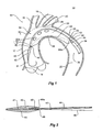
- FIG. 1 shows a schematic cross sectional view of a thoracic aorta
- the thoracic aorta 10 comprises an ascending aorta 12 which receives blood from the heart though an aortic valve 14.
- the ascending aorta there is a thoracic arch 15 with branches for the great vessels, the innominate artery 16, the left common carotid artery 18 and the left subclavian artery 20.
- the aorta after these great vessels is referred to as the descending aorta 22 and it is in this region that a thoracic aortic aneurysm can occur.
- a thoracic aortic aneurysm part of the wall 24 of the descending aorta swells and can burst with serious consequences.
- the thoracic aortic aneurysm can extend to close to the great vessels or include the great vessels and hence it may be necessary to deploy a stent graft with side branches to extend into the great vessels.
- the thoracic arch has an inner side curve 26 and an outer side curve 28.
- a deployment device 30 has been deployed up through the descending aorta over a pre-placed guide wire 31.
- the proximal end of the deployment device extends over the thoracic arch and into the ascending aorta 12.
- a sheath 36 of the deployment device has been withdrawn to partially release the stent graft 32 but the stent graft is still retained to the deployment device at region 40 at the proximal end 31 of the stent graft 32 and at region 42 at the distal end 33 of the stent graft 32.
- the stent graft 32 includes three fenestrations 32a into which are intended to be deployed side branch stents or covered stents to maintain the patency of the great vessels when the stent graft is released into the thoracic arch.
- the delivery device includes a guide wire catheter 44 made from stainless steel or NitinolTM.
- the guide wire catheter is resilient so that it can be bent to fit the shape of the thoracic arch. The bending of the guide wire catheter can caused by engagement with the wall of the aorta and hence the curve of the delivery device would be against the outer curve 28 of the thoracic arch. As this is where the great arteries branch off from the thoracic arch this does not allow working space adjacent to the major arteries and therefore the curving mechanism of the present invention is used.
- Part of the pusher catheter 34 of the deployment device can be seen at the distal end of the stent graft 32.
- the pusher catheter has a pusher lumen 34a (see also Figure 3 ) through which passes the guide wire catheter 44.
- the guide wire catheter 44 extending through the pusher lumen 34a is able to move longitudinally and rotationally with respect to the pusher catheter 34.
- the deployment device includes a nose cone dilator 45 at its proximal end and the lumen 47 of the guide wire catheter 44 extends to and through the nose cone dilator 45.
- the nose cone dilator 45 is at the proximal end of the deployment device and the guide wire 44 catheter extends to and through the nose cone dilator 45.
- the guide wire catheter has a guide wire lumen 47 therethrough.
- the guide wire lumen 47 continues through the nose cone dilator 45.
- the nose cone dilator 45 has a notch 43 formed in it upper surface and the nose cone dilator 45 is formed from a radiopaque material such as a radiopaque polyurethane such that the orientation of the delivery device within the thoracic arch can be visualised by suitable radiographic techniques.
- the curving mechanism includes a pull wire 46 which is fastened to the nose cone dilator 45 at the distal end 45a thereof where it joins to the guide wire catheter.
- the pull wire 46 can be fastened at 49 to a sleeve 48 which is fastened such as by welding to the guide wire catheter and the nose cone dilator is fixed to the sleeve 48 by adhesive or the like.
- the pull wire is joined at 49 to the nose cone dilator 45 on the opposite side to the notch 43.
- the pull wire 46 extends through the lumen of the stent graft 32 and into the pusher lumen 34a of the pusher catheter 34 (but outside the guide wire catheter 36).
- the pull wire then extends back to a handle of the deployment device as is discussed below and shown in Figures 3 to 5 .
- Pulling on the pull wire has caused the nose cone dilator to be pulled towards the pusher catheter which has caused the guide wire catheter to bend thereby forming a curve in the delivery device proximal end which more approximates the shape of the inner curve 26 of the thoracic arch and leaving some working space 50 between the stent graft and the outer curve 28 of the thoracic arch.
- the notch 43 on the nose cone dilator is on the outside of the curve of the delivery device.
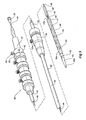
- FIGS 3 and 4 depicts a delivery device 30 according to one embodiment of the invention.
- The, delivery device 30 has a guide wire catheter 44 which extends from a distal handle 52 to the proximal tapered nose cone dilator 45 longitudinally through a passageway or lumen 34a of a pusher catheter 34 which is connected to the handle 52 at its distal end.
- An introducer sheath 36 fits coaxially around the delivery catheter 34 and extends from a tapered proximal end 36a which optionally includes a radiopaque marker to a connector valve and hub 54 attached to the distal end of the sheath.
- the introducer sheath 36 extends proximally to the nose cone dilator 45 and covers the stent graft 32 during introduction of the deployment device into a patient and is withdrawn distally to expose the stent graft 32 during deployment when the deployment device is in a selected position within the vasculature of a patient.
- the stent graft or implantable device 32 is carried on the guide wire catheter 44 proximally of the pusher catheter 34 and distally of the nose cone dilator 45.
- the stent graft 32 comprises a tubular body of a biocompatible material and a plurality of self expanding stents (not shown for clarity).
- Connector valve and hub 54 includes a silicone disk assembly (not shown) for preventing the backflow of fluids therethrough.
- the disk assembly includes a slit for the insertion of the nose cone dilator 45 and delivery catheter 34.
- Connector and hub 54 also includes side arm 54a to which a tube may be connected for introducing and aspirating fluids therethrough.
- Nose cone dilator 45 includes a tapered proximal end 45a for accessing and dilating a vascular access site over a well-known and commercially available wire guide (not shown).
- the wire guide is inserted in the vessel with an introducer needle using, for example, the well-known percutaneous vascular access Seldinger technique.
- a well-known male Luer lock connector hub 58 is attached at the distal end of the guide wire catheter 44 for connection to syringes and other medical apparatus.
- the handle 52 at the distal end of the pusher catheter 34 remains outside a patient in use and carries the trigger wire release handle mechanisms used to release the various portions of the stent graft.
- the proximal end the stent graft 32 is retained on the delivery device by the use of trigger wires (not shown) connected to one of the release handles, the distal end of the stent graft is retained on the delivery device by the use of trigger wires (not shown) connected to another the release handles.
- the handle also includes a release mechanism for a release wire for diameter reducing ties (not shown) for the stent graft.
- the pull wire 46 extends from where it is fastened to the distal end of the nose cone dilator 45 (see Figure 2 ) through the lumen 34a of the stent graft 32 and into the pusher lumen of the pusher catheter 34.
- the pull wire then extends back to a handle 52 of the deployment device where it is fastened to pull wire grip 60 which can be clamped to the handle by thumb screw 62.
- pulling on the grip 60 in the distal direction as shown by the arrow 64 causes the pull wire 46 to bend the proximal end of the guide wire catheter between the proximal end of the pusher catheter 34 and the distal end of the nose cone dilator 45 to form the curve as shown.
- the thumb screw 62 can be used to clamp the grip 60 to the handle to hold the curvature during subsequent stages of the introduction procedure.
- the stent graft 32 is still retained on the deployment device at region 40 at the proximal end 31 of the stent graft and at region 42 at the distal end of the stent graft.
- Subsequent stages of the introduction procedure can include catheterization of the fenestrations and introduction of a suitable side arm delivery device but before actual deployment of the side arms the pull wire can be released and the stent graft released from the delivery device. This would ensure that a side arm is not dislodged when the main stent graft settles into its final position in the thoracic arch.
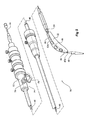
- Figure 5 shows an alternative embodiment of delivery or deployment device according to the present invention.
- the same reference numerals are used for items corresponding to those in Figure 3 and 4 .
- the delivery device 70 of this embodiment has two variations from the earlier embodiment. First there is a winch arrangement for pulling the pull wire and second there is a pusher extension to reduce the amount of the guide wire catheter which is caused to bend by pulling on the pull wire. These two variations need not be used together and could be applied separately.
- the handle 72 of the deployment device 70 has a winch assembly 74 which includes a winding handle 76 connected to a winch drum 78 within the winch assembly 74 and the pull wire is wound around the winch drum 78.
- the winch arrangement includes a releasable locking mechanism (not shown) to hold the winch drum in a selected rotational position.
- a catheter extension 80 through which passes the guide wire catheter 44 and the pull 46 wire parallel to but outside the guide wire catheter.
- the catheter extension 80 extends part way into the lumen of the stent graft 32. This restricts the length of guide wire catheter which is bent by the pulling on the pull wire.
- Rotating the winding handle 76 causes the pull wire 46 to bend the proximal end of the guide wire catheter between the proximal end 80a of the pusher catheter extension 80 and the distal end 45a of the nose cone dilator 45 to form the curve as shown in Figure 5 .
- the releasable locking mechanism holds the curvature.
- the winch assembly can be placed on other parts of the handle 72.
Landscapes
- Health & Medical Sciences (AREA)
- Engineering & Computer Science (AREA)
- Biomedical Technology (AREA)
- Life Sciences & Earth Sciences (AREA)
- General Health & Medical Sciences (AREA)
- Heart & Thoracic Surgery (AREA)
- Animal Behavior & Ethology (AREA)
- Public Health (AREA)
- Veterinary Medicine (AREA)
- Hematology (AREA)
- Anesthesiology (AREA)
- Oral & Maxillofacial Surgery (AREA)
- Cardiology (AREA)
- Transplantation (AREA)
- Vascular Medicine (AREA)
- Pulmonology (AREA)
- Biophysics (AREA)
- Media Introduction/Drainage Providing Device (AREA)
- Prostheses (AREA)
Applications Claiming Priority (2)
| Application Number | Priority Date | Filing Date | Title |
|---|---|---|---|
| US19014208P | 2008-08-26 | 2008-08-26 | |
| PCT/US2009/004807 WO2010024869A1 (en) | 2008-08-26 | 2009-08-24 | Thoracic introducer |
Publications (2)
| Publication Number | Publication Date |
|---|---|
| EP2317958A1 EP2317958A1 (en) | 2011-05-11 |
| EP2317958B1 true EP2317958B1 (en) | 2012-02-29 |
Family
ID=41202851
Family Applications (1)
| Application Number | Title | Priority Date | Filing Date |
|---|---|---|---|
| EP09789196A Active EP2317958B1 (en) | 2008-08-26 | 2009-08-24 | Thoracic introducer |
Country Status (5)
| Country | Link |
|---|---|
| US (1) | US8911488B2 (enExample) |
| EP (1) | EP2317958B1 (enExample) |
| JP (1) | JP5526311B2 (enExample) |
| AT (1) | ATE547072T1 (enExample) |
| WO (1) | WO2010024869A1 (enExample) |
Families Citing this family (34)
| Publication number | Priority date | Publication date | Assignee | Title |
|---|---|---|---|---|
| WO2008107885A2 (en) | 2007-03-05 | 2008-09-12 | Alon Shalev | Multi-component expandable supportive bifurcated endoluminal grafts and methods for using same |
| CA2709278A1 (en) | 2007-12-15 | 2009-06-25 | Endospan Ltd. | Extra-vascular wrapping for treating aneurysmatic aorta in conjunction with endovascular stent-graft and methods thereof |
| JP5629871B2 (ja) * | 2009-04-28 | 2014-11-26 | エンドロジックス、インク | 移植片あるいは移植片システムを配置する装置および方法 |
| US8870938B2 (en) | 2009-06-23 | 2014-10-28 | Endospan Ltd. | Vascular prostheses for treating aneurysms |
| WO2011004374A1 (en) | 2009-07-09 | 2011-01-13 | Endospan Ltd. | Apparatus for closure of a lumen and methods of using the same |
| WO2011064782A2 (en) | 2009-11-30 | 2011-06-03 | Endospan Ltd. | Multi-component stent-graft system for implantation in a blood vessel with multiple branches |
| CA2783554C (en) | 2009-12-08 | 2016-02-16 | Endospan Ltd. | Endovascular stent-graft system with fenestrated and crossing stent-grafts |
| CA2785953C (en) | 2009-12-31 | 2016-02-16 | Endospan Ltd. | Endovascular flow direction indicator |
| US10028814B2 (en) * | 2010-02-03 | 2018-07-24 | Covidien Lp | X-shaped device and method for deployment and placement of a patch |
| EP2533722B1 (en) | 2010-02-08 | 2017-03-29 | Endospan Ltd. | Thermal energy application for prevention and management of endoleaks in stent-grafts |
| US9326872B2 (en) | 2010-08-17 | 2016-05-03 | W. L. Gore & Associates, Inc. | Forced deployment sequence handle assembly with independent actuating mechanism |
| US9526638B2 (en) | 2011-02-03 | 2016-12-27 | Endospan Ltd. | Implantable medical devices constructed of shape memory material |
| WO2012111006A1 (en) | 2011-02-17 | 2012-08-23 | Endospan Ltd. | Vascular bands and delivery systems therefor |
| EP2680788A4 (en) | 2011-03-02 | 2014-12-10 | Endospan Ltd | OUTER RING WITH REDUCED VOLTAGE FOR THE TREATMENT OF AORTIC ANATOMY |
| US8574287B2 (en) | 2011-06-14 | 2013-11-05 | Endospan Ltd. | Stents incorporating a plurality of strain-distribution locations |
| US8951298B2 (en) | 2011-06-21 | 2015-02-10 | Endospan Ltd. | Endovascular system with circumferentially-overlapping stent-grafts |
| WO2013005207A1 (en) | 2011-07-07 | 2013-01-10 | Endospan Ltd. | Stent fixation with reduced plastic deformation |
| US9839510B2 (en) | 2011-08-28 | 2017-12-12 | Endospan Ltd. | Stent-grafts with post-deployment variable radial displacement |
| WO2013065040A1 (en) | 2011-10-30 | 2013-05-10 | Endospan Ltd. | Triple-collar stent-graft |
| WO2013084235A2 (en) | 2011-12-04 | 2013-06-13 | Endospan Ltd. | Branched stent-graft system |
| WO2013171730A1 (en) | 2012-05-15 | 2013-11-21 | Endospan Ltd. | Stent-graft with fixation elements that are radially confined for delivery |
| US9668892B2 (en) | 2013-03-11 | 2017-06-06 | Endospan Ltd. | Multi-component stent-graft system for aortic dissections |
| US9375550B2 (en) | 2013-03-15 | 2016-06-28 | St. Jude Medical, Atrial Fibrillation Division, Inc. | Catheter actuators providing mechanical advantage |
| CN103349809B (zh) * | 2013-06-25 | 2015-06-24 | 胡寒竹 | 一种锁扣式鼻胆管引导装置及其简易制作方法 |
| US10603197B2 (en) | 2013-11-19 | 2020-03-31 | Endospan Ltd. | Stent system with radial-expansion locking |
| EP3068339B1 (en) | 2014-12-18 | 2017-11-01 | Endospan Ltd. | Endovascular stent-graft with fatigue-resistant lateral tube |
| EP3037072B1 (en) | 2014-12-23 | 2020-04-22 | Cook Medical Technologies LLC | Introducer with side opening |
| US10092428B2 (en) | 2014-12-30 | 2018-10-09 | Cook Medical Technologies Llc | Low profile prosthesis delivery device |
| CN109069139B (zh) * | 2016-01-13 | 2021-04-20 | 箭国际有限责任公司 | 具有用于鞘转移的导引器的血管闭合系统 |
| US10610393B2 (en) | 2016-03-24 | 2020-04-07 | Cook Medical Technologies Llc | Wire retention and release mechanisms |
| US10709541B2 (en) | 2017-04-28 | 2020-07-14 | Cook Medical Technologies Llc | Systems and methods for adjusting the diameter of an endoluminal prosthesis and an endoluminal prosthesis configured for the same |
| US11896473B2 (en) | 2020-07-13 | 2024-02-13 | Covidien Lp | Surgical mesh deployment device |
| US20240157095A1 (en) * | 2021-03-23 | 2024-05-16 | Ann & Robert H. Lurie Children's Hosp. of Chicago | Needle and guide wire insertion system |
| DE102024130699A1 (de) * | 2024-10-08 | 2026-04-09 | Acandis Gmbh | Dilatator; Behandlungssystem mit wenigstens einem Dilatator |
Family Cites Families (22)
| Publication number | Priority date | Publication date | Assignee | Title |
|---|---|---|---|---|
| US4588399A (en) * | 1980-05-14 | 1986-05-13 | Shiley Incorporated | Cannula with radiopaque tip |
| US5693083A (en) * | 1983-12-09 | 1997-12-02 | Endovascular Technologies, Inc. | Thoracic graft and delivery catheter |
| US4586923A (en) * | 1984-06-25 | 1986-05-06 | Cordis Corporation | Curving tip catheter |
| US5203777A (en) * | 1992-03-19 | 1993-04-20 | Lee Peter Y | Radiopaque marker system for a tubular device |
| US5683451A (en) * | 1994-06-08 | 1997-11-04 | Cardiovascular Concepts, Inc. | Apparatus and methods for deployment release of intraluminal prostheses |
| JPH1176403A (ja) * | 1997-07-11 | 1999-03-23 | Olympus Optical Co Ltd | 外科用処置具 |
| US6475226B1 (en) * | 1999-02-03 | 2002-11-05 | Scimed Life Systems, Inc. | Percutaneous bypass apparatus and method |
| US6126649A (en) * | 1999-06-10 | 2000-10-03 | Transvascular, Inc. | Steerable catheter with external guidewire as catheter tip deflector |
| US20030018343A1 (en) * | 2001-07-23 | 2003-01-23 | Mathis Mark L. | Medical device delivery system having reduced loading, and method |
| AU2003273575B2 (en) * | 2002-05-29 | 2007-12-06 | Cook Incorporated | Trigger wire system for a prosthesis deployment device |
| DK1517651T3 (da) * | 2002-06-28 | 2010-08-02 | Cook Inc | Thorax-aortal-aneurisme-stentimplantat |
| US6733489B2 (en) * | 2002-09-26 | 2004-05-11 | Angiodynamics, Inc. | Vascular orientation marker for determining the orientation of a blood vessel |
| US6984244B2 (en) * | 2003-03-27 | 2006-01-10 | Endovascular Technologies, Inc. | Delivery system for endoluminal implant |
| US20040267348A1 (en) * | 2003-04-11 | 2004-12-30 | Gunderson Richard C. | Medical device delivery systems |
| US20070198078A1 (en) | 2003-09-03 | 2007-08-23 | Bolton Medical, Inc. | Delivery system and method for self-centering a Proximal end of a stent graft |
| US7553323B1 (en) * | 2004-01-08 | 2009-06-30 | Perez Juan I | Steerable endovascular graft delivery system |
| US8287583B2 (en) * | 2005-01-10 | 2012-10-16 | Taheri Laduca Llc | Apparatus and method for deploying an implantable device within the body |
| US20070270781A1 (en) | 2006-01-06 | 2007-11-22 | Robert Burgermeister | Medical delivery system and method for delivery of a medically useful payload |
| US8740964B2 (en) * | 2006-01-18 | 2014-06-03 | Cook Medical Technologies Llc | Endoluminal delivery device |
| DE602007004493D1 (de) | 2006-07-24 | 2010-03-11 | Cook Inc | Einführhilfe für eine medizinische vorrichtung mit andockanordnung |
| US20080114440A1 (en) * | 2006-11-13 | 2008-05-15 | Sage Medical Technologies, Inc | Methods and devices for deploying an implant in curved anatomy |
| US20080228255A1 (en) | 2007-03-13 | 2008-09-18 | Medtronic Vascular, Inc. | Positionable Stent-Graft Delivery System and Method |
-
2009
- 2009-08-24 US US13/059,499 patent/US8911488B2/en active Active
- 2009-08-24 WO PCT/US2009/004807 patent/WO2010024869A1/en not_active Ceased
- 2009-08-24 EP EP09789196A patent/EP2317958B1/en active Active
- 2009-08-24 AT AT09789196T patent/ATE547072T1/de active
- 2009-08-24 JP JP2011524980A patent/JP5526311B2/ja active Active
Also Published As
| Publication number | Publication date |
|---|---|
| US8911488B2 (en) | 2014-12-16 |
| WO2010024869A1 (en) | 2010-03-04 |
| ATE547072T1 (de) | 2012-03-15 |
| EP2317958A1 (en) | 2011-05-11 |
| JP2012501206A (ja) | 2012-01-19 |
| JP5526311B2 (ja) | 2014-06-18 |
| US20110230947A1 (en) | 2011-09-22 |
Similar Documents
| Publication | Publication Date | Title |
|---|---|---|
| EP2317958B1 (en) | Thoracic introducer | |
| EP1517652B1 (en) | Thoracic introducer | |
| US8864808B2 (en) | Endoluminal delivery assembly | |
| EP2358312B1 (en) | Apparatus for curving an implantable medical device in a lumen | |
| EP3017790B1 (en) | Endovascular stent graft assembly and delivery device | |
| EP2240126B1 (en) | Apparatus for and method of fitting a stent-graft or similar device | |
| US20050033400A1 (en) | Device and method for staged implantation of a graft for vascular repair | |
| CN103732282A (zh) | 具有两个柔性端部的引导线和利用其进入分支血管的方法 | |
| EP3058901B1 (en) | Implant introducer with helical trigger wire | |
| US20240091507A1 (en) | Looped wire for advanced stent grafts and methods of using same | |
| EP3315101B1 (en) | Preloaded branch wire loop constraint | |
| EP1813232B1 (en) | Deployment catheter for medical implant devices | |
| US20140121751A1 (en) | Cannula attachment in endoluminal delivery devices | |
| EP2727562A1 (en) | Cannula attachment in endoluminal delivery devices | |
| WO2025054515A1 (en) | A constraint arrangement for a stent-graft loaded onto a delivery system |
Legal Events
| Date | Code | Title | Description |
|---|---|---|---|
| PUAI | Public reference made under article 153(3) epc to a published international application that has entered the european phase |
Free format text: ORIGINAL CODE: 0009012 |
|
| 17P | Request for examination filed |
Effective date: 20101111 |
|
| AK | Designated contracting states |
Kind code of ref document: A1 Designated state(s): AT BE BG CH CY CZ DE DK EE ES FI FR GB GR HR HU IE IS IT LI LT LU LV MC MK MT NL NO PL PT RO SE SI SK SM TR |
|
| AX | Request for extension of the european patent |
Extension state: AL BA RS |
|
| GRAP | Despatch of communication of intention to grant a patent |
Free format text: ORIGINAL CODE: EPIDOSNIGR1 |
|
| RIN1 | Information on inventor provided before grant (corrected) |
Inventor name: HARTLEY, DAVID, E. Inventor name: GREENBERG, ROY, K. Inventor name: CHUTER, TIMOTHY, A. |
|
| DAX | Request for extension of the european patent (deleted) | ||
| RAP1 | Party data changed (applicant data changed or rights of an application transferred) |
Owner name: WILLIAM A. COOK AUSTRALIA PTY. LTD. Owner name: THE CLEVELAND CLINIC FOUNDATION Owner name: COOK MEDICAL TECHNOLOGIES LLC |
|
| GRAS | Grant fee paid |
Free format text: ORIGINAL CODE: EPIDOSNIGR3 |
|
| RAP1 | Party data changed (applicant data changed or rights of an application transferred) |
Owner name: THE CLEVELAND CLINIC FOUNDATION Owner name: WILLIAM A. COOK AUSTRALIA PTY. LTD. Owner name: COOK MEDICAL TECHNOLOGIES LLC |
|
| GRAA | (expected) grant |
Free format text: ORIGINAL CODE: 0009210 |
|
| AK | Designated contracting states |
Kind code of ref document: B1 Designated state(s): AT BE BG CH CY CZ DE DK EE ES FI FR GB GR HR HU IE IS IT LI LT LU LV MC MK MT NL NO PL PT RO SE SI SK SM TR |
|
| REG | Reference to a national code |
Ref country code: CH Ref legal event code: EP Ref country code: GB Ref legal event code: FG4D |
|
| REG | Reference to a national code |
Ref country code: AT Ref legal event code: REF Ref document number: 547072 Country of ref document: AT Kind code of ref document: T Effective date: 20120315 |
|
| REG | Reference to a national code |
Ref country code: IE Ref legal event code: FG4D |
|
| REG | Reference to a national code |
Ref country code: DE Ref legal event code: R096 Ref document number: 602009005680 Country of ref document: DE Effective date: 20120426 |
|
| REG | Reference to a national code |
Ref country code: NL Ref legal event code: VDEP Effective date: 20120229 |
|
| LTIE | Lt: invalidation of european patent or patent extension |
Effective date: 20120229 |
|
| PG25 | Lapsed in a contracting state [announced via postgrant information from national office to epo] |
Ref country code: HR Free format text: LAPSE BECAUSE OF FAILURE TO SUBMIT A TRANSLATION OF THE DESCRIPTION OR TO PAY THE FEE WITHIN THE PRESCRIBED TIME-LIMIT Effective date: 20120229 Ref country code: NO Free format text: LAPSE BECAUSE OF FAILURE TO SUBMIT A TRANSLATION OF THE DESCRIPTION OR TO PAY THE FEE WITHIN THE PRESCRIBED TIME-LIMIT Effective date: 20120529 Ref country code: NL Free format text: LAPSE BECAUSE OF FAILURE TO SUBMIT A TRANSLATION OF THE DESCRIPTION OR TO PAY THE FEE WITHIN THE PRESCRIBED TIME-LIMIT Effective date: 20120229 Ref country code: IS Free format text: LAPSE BECAUSE OF FAILURE TO SUBMIT A TRANSLATION OF THE DESCRIPTION OR TO PAY THE FEE WITHIN THE PRESCRIBED TIME-LIMIT Effective date: 20120629 Ref country code: LT Free format text: LAPSE BECAUSE OF FAILURE TO SUBMIT A TRANSLATION OF THE DESCRIPTION OR TO PAY THE FEE WITHIN THE PRESCRIBED TIME-LIMIT Effective date: 20120229 |
|
| PG25 | Lapsed in a contracting state [announced via postgrant information from national office to epo] |
Ref country code: BE Free format text: LAPSE BECAUSE OF FAILURE TO SUBMIT A TRANSLATION OF THE DESCRIPTION OR TO PAY THE FEE WITHIN THE PRESCRIBED TIME-LIMIT Effective date: 20120229 Ref country code: LV Free format text: LAPSE BECAUSE OF FAILURE TO SUBMIT A TRANSLATION OF THE DESCRIPTION OR TO PAY THE FEE WITHIN THE PRESCRIBED TIME-LIMIT Effective date: 20120229 Ref country code: GR Free format text: LAPSE BECAUSE OF FAILURE TO SUBMIT A TRANSLATION OF THE DESCRIPTION OR TO PAY THE FEE WITHIN THE PRESCRIBED TIME-LIMIT Effective date: 20120530 Ref country code: PT Free format text: LAPSE BECAUSE OF FAILURE TO SUBMIT A TRANSLATION OF THE DESCRIPTION OR TO PAY THE FEE WITHIN THE PRESCRIBED TIME-LIMIT Effective date: 20120629 Ref country code: FI Free format text: LAPSE BECAUSE OF FAILURE TO SUBMIT A TRANSLATION OF THE DESCRIPTION OR TO PAY THE FEE WITHIN THE PRESCRIBED TIME-LIMIT Effective date: 20120229 |
|
| REG | Reference to a national code |
Ref country code: AT Ref legal event code: MK05 Ref document number: 547072 Country of ref document: AT Kind code of ref document: T Effective date: 20120229 |
|
| PG25 | Lapsed in a contracting state [announced via postgrant information from national office to epo] |
Ref country code: CY Free format text: LAPSE BECAUSE OF FAILURE TO SUBMIT A TRANSLATION OF THE DESCRIPTION OR TO PAY THE FEE WITHIN THE PRESCRIBED TIME-LIMIT Effective date: 20120229 |
|
| PG25 | Lapsed in a contracting state [announced via postgrant information from national office to epo] |
Ref country code: DK Free format text: LAPSE BECAUSE OF FAILURE TO SUBMIT A TRANSLATION OF THE DESCRIPTION OR TO PAY THE FEE WITHIN THE PRESCRIBED TIME-LIMIT Effective date: 20120229 Ref country code: EE Free format text: LAPSE BECAUSE OF FAILURE TO SUBMIT A TRANSLATION OF THE DESCRIPTION OR TO PAY THE FEE WITHIN THE PRESCRIBED TIME-LIMIT Effective date: 20120229 Ref country code: CZ Free format text: LAPSE BECAUSE OF FAILURE TO SUBMIT A TRANSLATION OF THE DESCRIPTION OR TO PAY THE FEE WITHIN THE PRESCRIBED TIME-LIMIT Effective date: 20120229 Ref country code: SI Free format text: LAPSE BECAUSE OF FAILURE TO SUBMIT A TRANSLATION OF THE DESCRIPTION OR TO PAY THE FEE WITHIN THE PRESCRIBED TIME-LIMIT Effective date: 20120229 Ref country code: SE Free format text: LAPSE BECAUSE OF FAILURE TO SUBMIT A TRANSLATION OF THE DESCRIPTION OR TO PAY THE FEE WITHIN THE PRESCRIBED TIME-LIMIT Effective date: 20120229 Ref country code: RO Free format text: LAPSE BECAUSE OF FAILURE TO SUBMIT A TRANSLATION OF THE DESCRIPTION OR TO PAY THE FEE WITHIN THE PRESCRIBED TIME-LIMIT Effective date: 20120229 Ref country code: PL Free format text: LAPSE BECAUSE OF FAILURE TO SUBMIT A TRANSLATION OF THE DESCRIPTION OR TO PAY THE FEE WITHIN THE PRESCRIBED TIME-LIMIT Effective date: 20120229 |
|
| PG25 | Lapsed in a contracting state [announced via postgrant information from national office to epo] |
Ref country code: IT Free format text: LAPSE BECAUSE OF FAILURE TO SUBMIT A TRANSLATION OF THE DESCRIPTION OR TO PAY THE FEE WITHIN THE PRESCRIBED TIME-LIMIT Effective date: 20120229 Ref country code: SK Free format text: LAPSE BECAUSE OF FAILURE TO SUBMIT A TRANSLATION OF THE DESCRIPTION OR TO PAY THE FEE WITHIN THE PRESCRIBED TIME-LIMIT Effective date: 20120229 |
|
| PLBE | No opposition filed within time limit |
Free format text: ORIGINAL CODE: 0009261 |
|
| STAA | Information on the status of an ep patent application or granted ep patent |
Free format text: STATUS: NO OPPOSITION FILED WITHIN TIME LIMIT |
|
| PG25 | Lapsed in a contracting state [announced via postgrant information from national office to epo] |
Ref country code: AT Free format text: LAPSE BECAUSE OF FAILURE TO SUBMIT A TRANSLATION OF THE DESCRIPTION OR TO PAY THE FEE WITHIN THE PRESCRIBED TIME-LIMIT Effective date: 20120229 |
|
| 26N | No opposition filed |
Effective date: 20121130 |
|
| REG | Reference to a national code |
Ref country code: DE Ref legal event code: R097 Ref document number: 602009005680 Country of ref document: DE Effective date: 20121130 |
|
| PG25 | Lapsed in a contracting state [announced via postgrant information from national office to epo] |
Ref country code: MC Free format text: LAPSE BECAUSE OF NON-PAYMENT OF DUE FEES Effective date: 20120831 |
|
| PG25 | Lapsed in a contracting state [announced via postgrant information from national office to epo] |
Ref country code: ES Free format text: LAPSE BECAUSE OF FAILURE TO SUBMIT A TRANSLATION OF THE DESCRIPTION OR TO PAY THE FEE WITHIN THE PRESCRIBED TIME-LIMIT Effective date: 20120609 |
|
| REG | Reference to a national code |
Ref country code: FR Ref legal event code: ST Effective date: 20130430 |
|
| PG25 | Lapsed in a contracting state [announced via postgrant information from national office to epo] |
Ref country code: BG Free format text: LAPSE BECAUSE OF FAILURE TO SUBMIT A TRANSLATION OF THE DESCRIPTION OR TO PAY THE FEE WITHIN THE PRESCRIBED TIME-LIMIT Effective date: 20120529 |
|
| PG25 | Lapsed in a contracting state [announced via postgrant information from national office to epo] |
Ref country code: FR Free format text: LAPSE BECAUSE OF NON-PAYMENT OF DUE FEES Effective date: 20120831 |
|
| PG25 | Lapsed in a contracting state [announced via postgrant information from national office to epo] |
Ref country code: MT Free format text: LAPSE BECAUSE OF FAILURE TO SUBMIT A TRANSLATION OF THE DESCRIPTION OR TO PAY THE FEE WITHIN THE PRESCRIBED TIME-LIMIT Effective date: 20120229 |
|
| REG | Reference to a national code |
Ref country code: CH Ref legal event code: PL |
|
| PG25 | Lapsed in a contracting state [announced via postgrant information from national office to epo] |
Ref country code: LI Free format text: LAPSE BECAUSE OF NON-PAYMENT OF DUE FEES Effective date: 20130831 Ref country code: TR Free format text: LAPSE BECAUSE OF FAILURE TO SUBMIT A TRANSLATION OF THE DESCRIPTION OR TO PAY THE FEE WITHIN THE PRESCRIBED TIME-LIMIT Effective date: 20120229 Ref country code: CH Free format text: LAPSE BECAUSE OF NON-PAYMENT OF DUE FEES Effective date: 20130831 |
|
| PG25 | Lapsed in a contracting state [announced via postgrant information from national office to epo] |
Ref country code: SM Free format text: LAPSE BECAUSE OF FAILURE TO SUBMIT A TRANSLATION OF THE DESCRIPTION OR TO PAY THE FEE WITHIN THE PRESCRIBED TIME-LIMIT Effective date: 20120229 Ref country code: LU Free format text: LAPSE BECAUSE OF NON-PAYMENT OF DUE FEES Effective date: 20120824 |
|
| PG25 | Lapsed in a contracting state [announced via postgrant information from national office to epo] |
Ref country code: HU Free format text: LAPSE BECAUSE OF FAILURE TO SUBMIT A TRANSLATION OF THE DESCRIPTION OR TO PAY THE FEE WITHIN THE PRESCRIBED TIME-LIMIT Effective date: 20090824 |
|
| PG25 | Lapsed in a contracting state [announced via postgrant information from national office to epo] |
Ref country code: MK Free format text: LAPSE BECAUSE OF FAILURE TO SUBMIT A TRANSLATION OF THE DESCRIPTION OR TO PAY THE FEE WITHIN THE PRESCRIBED TIME-LIMIT Effective date: 20120229 |
|
| P01 | Opt-out of the competence of the unified patent court (upc) registered |
Effective date: 20230629 |
|
| PGFP | Annual fee paid to national office [announced via postgrant information from national office to epo] |
Ref country code: DE Payment date: 20250827 Year of fee payment: 17 |
|
| PGFP | Annual fee paid to national office [announced via postgrant information from national office to epo] |
Ref country code: GB Payment date: 20250826 Year of fee payment: 17 |
|
| PGFP | Annual fee paid to national office [announced via postgrant information from national office to epo] |
Ref country code: IE Payment date: 20250819 Year of fee payment: 17 |