EP2317142B1 - Rotary compressor - Google Patents
Rotary compressor Download PDFInfo
- Publication number
- EP2317142B1 EP2317142B1 EP09805145.1A EP09805145A EP2317142B1 EP 2317142 B1 EP2317142 B1 EP 2317142B1 EP 09805145 A EP09805145 A EP 09805145A EP 2317142 B1 EP2317142 B1 EP 2317142B1
- Authority
- EP
- European Patent Office
- Prior art keywords
- cylinder
- vane
- compressor
- refrigerant
- connection hole
- Prior art date
- Legal status (The legal status is an assumption and is not a legal conclusion. Google has not performed a legal analysis and makes no representation as to the accuracy of the status listed.)
- Not-in-force
Links
Images


Classifications
-
- F—MECHANICAL ENGINEERING; LIGHTING; HEATING; WEAPONS; BLASTING
- F04—POSITIVE - DISPLACEMENT MACHINES FOR LIQUIDS; PUMPS FOR LIQUIDS OR ELASTIC FLUIDS
- F04C—ROTARY-PISTON, OR OSCILLATING-PISTON, POSITIVE-DISPLACEMENT MACHINES FOR LIQUIDS; ROTARY-PISTON, OR OSCILLATING-PISTON, POSITIVE-DISPLACEMENT PUMPS
- F04C29/00—Component parts, details or accessories of pumps or pumping installations, not provided for in groups F04C18/00 - F04C28/00
- F04C29/12—Arrangements for admission or discharge of the working fluid, e.g. constructional features of the inlet or outlet
-
- F—MECHANICAL ENGINEERING; LIGHTING; HEATING; WEAPONS; BLASTING
- F01—MACHINES OR ENGINES IN GENERAL; ENGINE PLANTS IN GENERAL; STEAM ENGINES
- F01C—ROTARY-PISTON OR OSCILLATING-PISTON MACHINES OR ENGINES
- F01C21/00—Component parts, details or accessories not provided for in groups F01C1/00 - F01C20/00
- F01C21/08—Rotary pistons
- F01C21/0809—Construction of vanes or vane holders
- F01C21/0818—Vane tracking; control therefor
- F01C21/0854—Vane tracking; control therefor by fluid means
- F01C21/0863—Vane tracking; control therefor by fluid means the fluid being the working fluid
-
- F—MECHANICAL ENGINEERING; LIGHTING; HEATING; WEAPONS; BLASTING
- F04—POSITIVE - DISPLACEMENT MACHINES FOR LIQUIDS; PUMPS FOR LIQUIDS OR ELASTIC FLUIDS
- F04C—ROTARY-PISTON, OR OSCILLATING-PISTON, POSITIVE-DISPLACEMENT MACHINES FOR LIQUIDS; ROTARY-PISTON, OR OSCILLATING-PISTON, POSITIVE-DISPLACEMENT PUMPS
- F04C18/00—Rotary-piston pumps specially adapted for elastic fluids
- F04C18/30—Rotary-piston pumps specially adapted for elastic fluids having the characteristics covered by two or more of groups F04C18/02, F04C18/08, F04C18/22, F04C18/24, F04C18/48, or having the characteristics covered by one of these groups together with some other type of movement between co-operating members
- F04C18/34—Rotary-piston pumps specially adapted for elastic fluids having the characteristics covered by two or more of groups F04C18/02, F04C18/08, F04C18/22, F04C18/24, F04C18/48, or having the characteristics covered by one of these groups together with some other type of movement between co-operating members having the movement defined in group F04C18/08 or F04C18/22 and relative reciprocation between the co-operating members
- F04C18/356—Rotary-piston pumps specially adapted for elastic fluids having the characteristics covered by two or more of groups F04C18/02, F04C18/08, F04C18/22, F04C18/24, F04C18/48, or having the characteristics covered by one of these groups together with some other type of movement between co-operating members having the movement defined in group F04C18/08 or F04C18/22 and relative reciprocation between the co-operating members with vanes reciprocating with respect to the outer member
- F04C18/3562—Rotary-piston pumps specially adapted for elastic fluids having the characteristics covered by two or more of groups F04C18/02, F04C18/08, F04C18/22, F04C18/24, F04C18/48, or having the characteristics covered by one of these groups together with some other type of movement between co-operating members having the movement defined in group F04C18/08 or F04C18/22 and relative reciprocation between the co-operating members with vanes reciprocating with respect to the outer member the inner and outer member being in contact along one line or continuous surfaces substantially parallel to the axis of rotation
- F04C18/3564—Rotary-piston pumps specially adapted for elastic fluids having the characteristics covered by two or more of groups F04C18/02, F04C18/08, F04C18/22, F04C18/24, F04C18/48, or having the characteristics covered by one of these groups together with some other type of movement between co-operating members having the movement defined in group F04C18/08 or F04C18/22 and relative reciprocation between the co-operating members with vanes reciprocating with respect to the outer member the inner and outer member being in contact along one line or continuous surfaces substantially parallel to the axis of rotation the surfaces of the inner and outer member, forming the working space, being surfaces of revolution
-
- F—MECHANICAL ENGINEERING; LIGHTING; HEATING; WEAPONS; BLASTING
- F04—POSITIVE - DISPLACEMENT MACHINES FOR LIQUIDS; PUMPS FOR LIQUIDS OR ELASTIC FLUIDS
- F04C—ROTARY-PISTON, OR OSCILLATING-PISTON, POSITIVE-DISPLACEMENT MACHINES FOR LIQUIDS; ROTARY-PISTON, OR OSCILLATING-PISTON, POSITIVE-DISPLACEMENT PUMPS
- F04C2240/00—Components
- F04C2240/30—Casings or housings
-
- F—MECHANICAL ENGINEERING; LIGHTING; HEATING; WEAPONS; BLASTING
- F04—POSITIVE - DISPLACEMENT MACHINES FOR LIQUIDS; PUMPS FOR LIQUIDS OR ELASTIC FLUIDS
- F04C—ROTARY-PISTON, OR OSCILLATING-PISTON, POSITIVE-DISPLACEMENT MACHINES FOR LIQUIDS; ROTARY-PISTON, OR OSCILLATING-PISTON, POSITIVE-DISPLACEMENT PUMPS
- F04C2240/00—Components
- F04C2240/80—Other components
- F04C2240/806—Pipes for fluids; Fittings therefor
-
- F—MECHANICAL ENGINEERING; LIGHTING; HEATING; WEAPONS; BLASTING
- F04—POSITIVE - DISPLACEMENT MACHINES FOR LIQUIDS; PUMPS FOR LIQUIDS OR ELASTIC FLUIDS
- F04C—ROTARY-PISTON, OR OSCILLATING-PISTON, POSITIVE-DISPLACEMENT MACHINES FOR LIQUIDS; ROTARY-PISTON, OR OSCILLATING-PISTON, POSITIVE-DISPLACEMENT PUMPS
- F04C2270/00—Control; Monitoring or safety arrangements
- F04C2270/56—Number of pump/machine units in operation
-
- F—MECHANICAL ENGINEERING; LIGHTING; HEATING; WEAPONS; BLASTING
- F04—POSITIVE - DISPLACEMENT MACHINES FOR LIQUIDS; PUMPS FOR LIQUIDS OR ELASTIC FLUIDS
- F04C—ROTARY-PISTON, OR OSCILLATING-PISTON, POSITIVE-DISPLACEMENT MACHINES FOR LIQUIDS; ROTARY-PISTON, OR OSCILLATING-PISTON, POSITIVE-DISPLACEMENT PUMPS
- F04C28/00—Control of, monitoring of, or safety arrangements for, pumps or pumping installations specially adapted for elastic fluids
- F04C28/06—Control of, monitoring of, or safety arrangements for, pumps or pumping installations specially adapted for elastic fluids specially adapted for stopping, starting, idling or no-load operation
- F04C28/065—Capacity control using a multiplicity of units or pumping capacities, e.g. multiple chambers, individually switchable or controllable
Definitions
- connection tube while press-fitting the connection tube into a connection hole of the cylinder, the periphery of the connection hole of the cylinder is swollen, which may cause the generation of gaps between the cylinder and bearings covering both upper and lower sides of the cylinder, thereby causing a refrigerant to be leaked from the rear side of the vane or a compression space, resulting in concern about lowering of the performance of the compressor.
- the casing 100 may have the inner space maintained in a discharge pressure state by a refrigerant discharged from the first and second compression parts 300 and 400 or from the first compression part 300.
- One gas suction pipe 140 through which a refrigerant is sucked between the first and second compression parts 300 and 400 may be connected to a circumferential surface of a lower portion of the casing 100.
- a discharge pipe 150 through which the refrigerant discharged after being compressed in the first and second compression parts 300 and 400 flows into a cooling system may be connected to an upper end of the casing 100.
- the upper bearing 110 and the lower bearing 120 are formed in a disc shape, and shaft supporting portions 112 and 122 having shaft holes 111 and 121 for supporting the shaft portion 231 of the rotation shaft 230 in a radial direction may protrude from respective centers thereof.
- the intermediate bearing 130 is formed in an annular shape with an inner diameter large enough to allow the eccentric portions of the rotation shaft 230 to be penetrated therethrough.
- a communication passage 131 through which a first suction hole 312 and a second suction hole 412 to be explained later can be communicated with the gas suction pipe 140 may be formed at one side of the intermediate bearing 130.
- the communication passage 131 of the intermediate bearing 130 may be provided with a horizontal path 132 formed in a radial direction to be communicated with the gas suction pipe 140, and a longitudinal path 133 formed at an end of the horizontal path 132 and formed through in a shaft direction for communicating the first suction hole 312 and the second suction hole 412 with the horizontal path 132.
- the horizontal path 132 may be recessed by a prescribed depth from an outer circumferential surface of the intermediate bearing 130 toward an inner circumferential surface thereof, namely, by a depth not completely enough to be communicated with the inner circumferential surface of the intermediate bearing 130.
- the first cylinder 310 may be provided with a first vane slot 311 formed at one side of its inner circumferential surface forming the first compression space V1 for allowing the first vane 330 to be linearly reciprocated, a first suction hole 312 formed at one side of the first vane slot 311 for inducing a refrigerant into the first compression space V1, and a first discharge guiding groove (not shown) formed at another side of the first vane slot 311 by chamfering an edge at an opposite side of the first suction hole 312 with an inclination angle, so as to guide a refrigerant to be discharged into an inner space of the first muffler 360.
- the first suction hole 312 may be formed with an inclination angle by chamfering an edge of a lower surface of the first cylinder 310, contacted with an upper end of the longitudinal path 133 of the intermediate bearing 130, toward the inner circumferential surface of the first cylinder 310.
- connection hole 416 communicated with a common connection pipe 530 to be explained later is formed at one side of the vane chamber 413, namely, at a center of the second cylinder 410 to extend toward an outer circumferential surface of the second cylinder 410.
- a connection tube 531 for connecting the vane chamber 413 to the common connection pipe 530 is inserted into the connection hole 416 for coupling.
- the refrigerant supplied to the vane chamber 413 can be concentrated toward the second vane 430.
- a great pressure difference occurs between the pressure applied to one side surface of the second vane 430 by the first restricting passage 414 disposed in the second cylinder 410 and the pressure applied to another side surface of the second vane 430 by the second restricting passage 415. Accordingly, the pressure applied via the first restricting passage 414 shows a tendency to move toward the second restricting passage 415, thereby rapidly restricting the second vane 430 without vibration.
- the discharge pressure remains in the vane chamber 413 so as to form a type of intermediate pressure Pm.
- the intermediate pressure Pm of the vane chamber 413 is leaked via the second restricting passage 415 with pressure lower than that.
Landscapes
- Engineering & Computer Science (AREA)
- Mechanical Engineering (AREA)
- General Engineering & Computer Science (AREA)
- Applications Or Details Of Rotary Compressors (AREA)
- Rotary Pumps (AREA)
Description
- The present invention relates to a rotary compressor, and more particularly, a rotary compressor capable of enhancing a sealing force between a mode switching unit for switching an operation mode of the compressor and a chamber.
- In general, a refrigerant compressor is applied to a vapor compression type refrigerating cycle (hereinafter, referred to as 'refrigerating cycle'), such as a refrigerator or an air conditioner. A constant-speed type compressor driven at constant speed and an inverter type compressor capable of controlling rotation speed have been introduced as the refrigerant compressor.
- The refrigerant compressors are categorized as follows. A refrigerant compressor, in which a driving motor (typically, an electric motor) and a compression part operated by the driving motor are all installed in an inner space of a hermetic casing, is referred to as a hermetic type compressor, and a compressor of which the driving motor is separately installed outside the casing is referred to as an open type compressor. Home or commercial cooling apparatuses usually employ the hermetic type compressor. The refrigerant compressors may be categorized into a reciprocating type, a scroll type, a rotary type and the like according to a refrigerant compression mechanism.
- The rotary compressor compresses a refrigerant by use of a rolling piston eccentrically rotating in a compression space of a cylinder and a vane contacted with a rolling piston for partitioning the compression space of the cylinder into a suction chamber and a discharge chamber. In recent time, a variable capacity type rotary compressor capable of varying a cooling capacity of the compressor according to the change in a load has been introduced. Well-known technologies for varying the cooling capacity of the compressor include applying an inverter motor, and varying a volume of a compression chamber by bypassing part of a compressed refrigerant out of a cylinder. However, for employing the inverter motor, a driver for driving the inerter motor is about 10 times as expensive as a driver of a constant-speed motor, thereby rising a fabrication cost of the compressor. On the other hand, for bypassing the refrigerant, a piping system becomes complicated and accordingly a flow resistance of the refrigerant is increased, thereby lowering efficiency of the compressor.
- Considering such drawbacks, a so-called modulation type variable capacity rotary compressor, in which at least one or more cylinders are provided and at least one of them is allowed for idling, has been introduced. The modulation type variable capacity rotary compressors may be categorized into a compressor employing a forward pressure mechanism and a compressor employing a recoil pressure mechanism according to a vane restriction method. For instance, the compressor employing the forward pressure mechanism is configured such that a discharge pressure is applied via a suction hole and accordingly a vane is pushed backwardly by pressure of a compression space so as to be restricted, while the compressor employing the recoil pressure mechanism is configured such that a back pressure of suction pressure or discharge pressure is applied to a rear side of the vane so as to selectively restrict the vane. The present invention is applied to a modulation type variable capacity rotary compressor (hereinafter, referred to as 'rotary compressor') employing the recoil pressure mechanism.
- The related art rotary compressor uses a connection tube between a connection pipe of a mode switching unit and a rear side of a vane when coupling the mode switching unit in order to apply a back pressure to the rear side of the vane. However, the connection tube cannot have a sufficient sealing area at the rear side of the vane, and accordingly a leakage of refrigerant may occur. As a result, a pressure of the rear side of the vane cannot be quickly changed, which may cause vibration of the vane, thereby lowering the performance of the compressor or increasing noise thereof.
- Furthermore, while press-fitting the connection tube into a connection hole of the cylinder, the periphery of the connection hole of the cylinder is swollen, which may cause the generation of gaps between the cylinder and bearings covering both upper and lower sides of the cylinder, thereby causing a refrigerant to be leaked from the rear side of the vane or a compression space, resulting in concern about lowering of the performance of the compressor.
- Document
WO2006/090977 discloses a modulation type variable capacity rotary compressor as known from the prior art, which comprises the features defined in the preamble ofindependent claim 1. The compressor also has a cylinder provided with a connection hole allowing a vane chamber to communicate with the mode switching unit by inserting a connection tube. - Therefore, to solve the problems of the related art rotary compressor, an object of the present invention is to a rotary compressor capable of preventing the leakage of refrigerant, which supports the vane, by ensuring a sealing area between the connection tube and the rear side of the vane.
- Another object of the present invention is to provide a rotary compressor capable of reducing the deformation of the cylinder when press-fitting the connection tube and accordingly preventing the leakage of refrigerant between the cylinder and bearings, resulting in improvement of the performance of the compressor.
- To achieve these and other advantages and in accordance with the purpose of the present invention, as embodied and broadly described herein, there is provided a rotary compressor according to
independent claim 1. - In the rotary compressor according to the present invention, the connecting protrusion is formed at the inner circumferential surface of the vane chamber so as to increase a sealing area between the connection hole and the connecting tube connected to the vane chamber, and the size of the connection hole is definitely designated so as to prevent the deformation of the cylinder when press-fitting the connection tube into the connection hole. Accordingly, the sealing area between the connection hole and the connection tube is increased so as to remarkably reduce the amount of leaked refrigerant from the vane chamber, and also a fast and accurate mode switching of the vane can be achieved so as to improve the performance of the compressor and prevent noise generation due to the vibration of the vane in advance.
- By providing a stepped connecting protrusion having a smaller curvature than the inner circumferential surface of the vane chamber, refrigerant supplied into the vane chamber is concentrated toward the vane.
-
-
FIG. 1 is a schematic view of a refrigerating cycle including a variable capacity type rotary compressor in accordance with the present invention; -
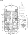
FIG. 2 is a longitudinal cross-sectional view showing an inside of the rotary compressor in accordance withFIG 1 by being longitudinally cut based upon a vane; -
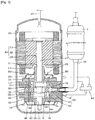
FIG. 3 is a longitudinal cross-sectional view showing an inside of the rotary compressor in accordance withFIG 1 , by being longitudinally cut based upon a suction hole; -
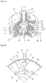
FIG. 4 is a perspective view showing a broken compression part of the rotary compressor in accordance withFIG. 1 ; -
FIG. 5 is a horizontal cross-sectional view showing a connection hole and a connection tube for connecting a common connection pipe in the rotary compressor in accordance withFIG. 1 ; -
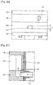
FIG. 6 is an enlarged horizontal cross-sectional view showing the connection hole and the connection tube in the rotary compressor in accordance withFIG. 5 ; -
FIG. 7 is an enlarged longitudinal cross-sectional view showing a relation between the connection hole and the connection tube in the rotary compressor in accordance withFIG. 1 ; -
FIG. 8 is a view showing restricting passages for restricting a second vane in the rotary compressor in accordance withFiG. 1 , which is a view taken along the line I -I ofFIG. 4 ; -
FIGS. 9 and10 are longitudinal and horizontal cross-sectional views showing a power mode of the rotary compressor in accordance withFIG. 1 ; -
FIGS. 11 and12 are longitudinal and horizontal cross-sectional views showing a saving mode of the rotary compressor in accordance withFIG. 1 ; -
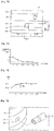
FIGS. 13 and 14 are graphs showing the changes in an amount of leaked refrigerant and the performance of the compressor depending on the changes in a sealing area between the connection hole and the connection tube in the rotary compressor in accordance with the present invention; -
FIG. 15 is an enlarged perspective view showing the connection hole and the connection tube in the rotary compressor in accordance withFIG. 5 ; -
FIG. 16 is a front view showing the size of the connection hole in accordance withFIG. 5 ; -
FIGS. 17 and 18 are graphs showing the deformation level of a cylinder and the changes in the performance of the compressor depending on the changes in a thickness of both sides of the connection hole in the rotary compressor in accordance with the present invention; -
FIG. 19 is a perspective view showing an other embodiment of a connection hole and a connection tube for connecting a common connection pipe in the rotary compressor in accordance withFIG. 1 ; -
FIG. 20 is a front view showing the size of the connection hole in accordance withFIG. 9 ; and -
FIG. 21 is a main part longitudinal cross-sectional view showing an example of coupling a connection tube to a lower bearing in a rotary compressor, the example not falling within the scope of the claimed subject matter. - Description will now be given in detail of a rotary compressor in accordance with one embodiment of the present invention, with reference to the accompanying drawings.
- As shown in
FIG. 1 , a variable capacity typerotary compressor 1 according to the present invention may be configured such that a suction side thereof is connected to an outlet side of anevaporator 4 and simultaneously a discharge side thereof is connected to an inlet side of acondenser 2 so as to form a part of a closed loop refrigerating cycle including thecondenser 2, anexpansion apparatus 3 and theevaporator 4. Anaccumulator 5 for separating a refrigerant carried from theevaporator 4 to thecompressor 1 into a gaseous refrigerant and a liquid refrigerant may be connected between the discharge side of theevaporator 4 and the inlet side of thecompressor 1. - The
compressor 1, as shown inFIG. 2 , may include amotor part 200 installed at an upper side of an inner space of ahermetic casing 100 for generating a driving force, and first andsecond compression parts casing 100 for compressing a refrigerant by the driving force generated from themotor part 200. Amode switching unit 500 for switching an operation mode of thecompressor 1 such that thesecond compression part 400 is idled if necessary is installed outside the
casing 100. - The
casing 100 may have the inner space maintained in a discharge pressure state by a refrigerant discharged from the first andsecond compression parts first compression part 300. Onegas suction pipe 140 through which a refrigerant is sucked between the first andsecond compression parts casing 100. Adischarge pipe 150 through which the refrigerant discharged after being compressed in the first andsecond compression parts casing 100. - The
motor part 200 may include astator 210 fixed onto an inner circumferential surface of thecasing 100, arotor 220 rotatably disposed in thestator 210, and arotation shaft 230 shrink-fitted with therotor 220 so as to be rotated together with therotor 220. Themotor part 200 may be implemented as a constant-speed motor or an inverter motor. However, an operation mode of the compressor can be switched by idling any one of the first andsecond compression parts - The
rotation shaft 230 may include ashaft portion 231 coupled to therotor 220, and a firsteccentric portion 232 and a secondeccentric portion 233 both disposed at a lower end section of theshaft portion 231 to be eccentric to both right and left sides. The firsteccentric portion 232 and the secondeccentric portion 233 may be symmetric to each other with a phase difference of about 180°, and rotatably coupled respectively to a firstrolling piston 340 and a secondrolling piston 430, which will be explained later. - The
first compression part 300 may include afirst cylinder 310 formed in an annular shape and installed inside thecasing 100, afirst rolling piston 320 rotatably coupled to the firsteccentric portion 232 of therotation shaft 230 and configured to compress a refrigerant by being orbited in a first compression space V1 of thefirst cylinder 310, afirst vane 330 movably coupled to thefirst cylinder 310 in a radial direction, with a sealing surface of its one side being contacted with an outer circumferential surface of thefirst rolling piston 320, and configured to partition the first compression space V1 of thefirst cylinder 310 into a first suction chamber and a first discharge chamber, and avane spring 340 configured as a compression spring for elastically supporting a rear side of thefirst vane 330.Unexplained reference numeral 350 denotes a first discharge valve, and 360 denotes a first muffler. - The
second compression part 400 includes asecond cylinder 410
formed in an annular shape and installed below thefirst cylinder 310 inside thecasing 100, asecond rolling piston 420 rotatably coupled to the secondeccentric portion 233 of therotation shaft 230 and configured to compress a refrigerant by being orbited in a second compression space V2 of thesecond cylinder 410, and asecond vane 430 movable coupled to thesecond cylinder 410 in a radial direction, and contacted with an outer circumferential surface of thesecond rolling piston 420 so as to partition the second compression space V2 of thesecond cylinder 410 into a second suction chamber and a second discharge chamber or spaced from the outer circumferential surface of the second rolling piston 429 so as to communicate the second suction chamber with the second discharge chamber.Unexplained reference numeral 440 denotes a second discharge valve, and 450 denotes a second muffler. - Here, an upper bearing plate 110 (hereinafter, referred to as 'upper
bearing') covers the upper side of thefirst cylinder 310, and a lower bearing plate 120 (hereinafter, referred to as 'lower bearing') covers the lower side of thesecond cylinder 410. Also, an intermediate bearing plate (hereinafter, referred to as 'intermediate bearing') 130 is interposed between the lower side of thefirst cylinder 310 and the upper side of thesecond cylinder 410 so as to support therotation shaft 230 in a shaft direction with forming the first compression space V1 and the second compression space V2. - As shown in
FIGS. 3 and4 , theupper bearing 110 and thelower bearing 120 are formed in a disc shape, andshaft supporting portions shaft holes shaft portion 231 of therotation shaft 230 in a radial direction may protrude from respective centers thereof. Theintermediate bearing 130 is formed in an annular shape with an inner diameter large enough to allow the eccentric portions of therotation shaft 230 to be penetrated therethrough. Acommunication passage 131 through which afirst suction hole 312 and asecond suction hole 412 to be explained later can be communicated with thegas suction pipe 140 may be formed at one side of theintermediate bearing 130. - The
communication passage 131 of theintermediate bearing 130 may be provided with ahorizontal path 132 formed in a radial direction to be communicated with thegas suction pipe 140, and alongitudinal path 133 formed at an end of thehorizontal path 132 and formed through in a shaft direction for communicating thefirst suction hole 312 and thesecond suction hole 412 with thehorizontal path 132. Thehorizontal path 132 may be recessed by a prescribed depth from an outer circumferential surface of theintermediate bearing 130 toward an inner circumferential surface thereof, namely, by a depth not completely enough to be communicated with the inner circumferential surface of theintermediate bearing 130. - The
first cylinder 310 may be provided with a first vane slot 311 formed at one side of its inner circumferential surface forming the first compression space V1 for allowing thefirst vane 330 to be linearly reciprocated, afirst suction hole 312 formed at one side of the first vane slot 311 for inducing a refrigerant into the first compression space V1, and a first discharge guiding groove (not shown) formed at another side of the first vane slot 311 by chamfering an edge at an opposite side of thefirst suction hole 312 with an inclination angle, so as to guide a refrigerant to be discharged into an inner space of thefirst muffler 360. - The
second cylinder 410 is provided with asecond vane slot 411
formed at one side of its inner circumferential surface forming the second compression space V2 for allowing thesecond vane 430 to be linearly reciprocated, asecond suction hole 412 formed at one side of thesecond vane slot 411 for inducing a refrigerant into the second compression space V2, and a second discharge guiding groove (not shown) formed at another side of thesecond vane slot 411 by chamfering an edge at an opposite side of thesecond suction hole 412 with an inclination angle so as to guide a refrigerant to be discharged into an inner space of thesecond muffler 450. - The
first suction hole 312 may be formed with an inclination angle by chamfering an edge of a lower surface of thefirst cylinder 310, contacted with an upper end of thelongitudinal path 133 of theintermediate bearing 130, toward the inner circumferential surface of thefirst cylinder 310. - The
second suction hole 412 may be formed with an inclination angle by chamfering an edge of an upper surface of thesecond cylinder 410, contacted with a lower end of thelongitudinal path 133 of theintermediate bearing 130, toward the inner circumferential surface of thesecond cylinder 410. - Here, the
second vane slot 411 may be formed by cutting (recessing) thesecond cylinder 410 into a preset depth in a radial direction such that thesecond vane 430 can be linearly reciprocated. Avane chamber 413 is formed at a rear side of thesecond vane slot 411, namely, at a portion on an outer circumferential surface of thesecond cylinder 410, so as to be communicated with acommon connection pipe 530 to be explained later. - The
vane chamber 413 is hermetically coupled by the intermediate
bearing 130 and thelower bearing 120 contacting with its upper and lower surfaces so as to be isolated within the inner space of thecasing 100. Thevane chamber 413 may have a preset inner volume such that the rear surface of thesecond vane 430 can serve as a pressed surface by a refrigerant supplied via thecommon connection pipe 530 even if thesecond vane 430 is completely retracted to be accommodated within thesecond vane slot 411. - As shown in
FIG. 5 , aconnection hole 416 communicated with acommon connection pipe 530 to be explained later is formed at one side of thevane chamber 413, namely, at a center of thesecond cylinder 410 to extend toward an outer circumferential surface of thesecond cylinder 410. Aconnection tube 531 for connecting thevane chamber 413 to thecommon connection pipe 530 is inserted into theconnection hole 416 for coupling. - The
connection tube 531 may preferably be formed of the same material to thecommon connection pipe 530 because it is welded with thecommon connection pipe 530. Also, theconnection pipe 531 may be formed to have a large diameter portion at the side being connected to thecommon connection pipe 530 and a small diameter portion at the side being inserted into theconnection hole 416 of thesecond cylinder 410. Theconnection tube 531 may have the large diameter portion and the small diameter portion integrally formed with each other; however, a plurality of tubes having different diameters may be assembled to form theconnection tube 531. - As shown in
FIG. 6 , a connectingprotrusion 417 for increasing a contact area between theconnection hole 416 and theconnection tube 531 is protruded by a prescribed height from a periphery of theconnection hole 416 of thesecond cylinder 410 in which theconnection tube 531 is inserted, namely, from an inner circumferential surface of thevane chamber 413, so as to be stepped in the shaft direction. The length of the connectingprotrusion 417 may preferably be shorter than a diameter of theconnection hole 416 and not longer than an end of the connection tube 631. For example, referring toFIG. 7 , preferably, when a length L from an outer circumferential surface of thesecond cylinder 410 to an end of the connectingprotrusion 417, namely, the length of theconnection hole 416 is more than approximately 3 mm and a thickness t of the connectingprotrusion 417 is more than approximately 0.5 mm, the amount of leaked refrigerant may be minimized. - The connecting
protrusion 417 is stepped so as to have a curvature smaller than that of thevane chamber 413, as shown inFIG. 6 . - Accordingly, the refrigerant supplied to the
vane chamber 413 can be concentrated toward thesecond vane 430. - The pressed surface 432 of the
second vane 430 is supported by a refrigerant of a suction pressure or a refrigerant of a discharge pressure filled in thevane chamber 413 such that a sealing surface 431 thereof comes in contact with or is spaced from thesecond rolling piston 420 according to an operation mode of the compressor. Accordingly, in order to prevent beforehand compressor noise or efficiency degradation due to the vibration of thesecond vane 430, thesecond vane 430 should be restricted within thesecond vane slot 411 in a particular operation mode of the compressor, i.e., in a saving mode. To this end, a restriction method for the second vane using internal pressure of thecasing 100, as shown inFIG. 8 , may be proposed. - For example, the
second cylinder 410 may be provided with a high pressure side vane restricting passage (hereinafter, referred to as 'first restricting passage') 414 orthogonal to a motion direction of thesecond vane 430 or formed in a direction at least having a stagger angle with respect to thesecond vane 430. The first restrictingpassage 414 allows the inside of thecasing 100 to be communicated with thesecond vane slot 411 such that a refrigerant of discharge pressure filled in the inner space of thecasing 100 pushes thesecond vane 430 towards an opposite vane slot surface, thereby restricting thesecond vane 430. A lower pressure side vane restricting passage (hereinafter, referred to as 'second restricting passage') for allowing thesecond vane slot 411 to be communicated with thesecond suction hole 412 may be formed at an opposite side of the first restrictingpassage 414. The second restrictingpassage 415 generates a pressure difference from the first restrictingpassage 414 such that a refrigerant of discharge pressure introduced via the first restrictingpassage 414 flows through the second restrictingpassage 415, thereby quickly restricting thesecond vane 430. - The
mode switching unit 500, as shown inFIGS. 1 and2 , may include a low pressureside connection pipe 510 having one end diverged from thegas suction pipe 140, a high pressureside connection pipe 520 having one end connected to the inner space of thecasing 100, acommon connection pipe 530 having one end connected to thevane chamber 413 of thesecond cylinder 410 so as to be selectively communicated with the low pressureside connection pipe 510 and the high pressureside connection pipe 520, a firstmode switching valve 540 connected to thevane chamber 413 of thesecond cylinder 410 via thecommon connection pipe 530, and a secondmode switching valve 550 connected to the firstmode switching valve 540 for controlling the switching operation of thefirst switching valve 540. - A basic compression process of the variable capacity type rotary compressor according to the present invention will be described hereinafter.
- That is, when power is applied to the
stator 210 of themotor part 200 and therotor 220 is rotated accordingly, therotation shaft 230 is rotated together with therotor 220 so as to transfer the rotational force of themotor part 200 to thefirst compression part 300 and thesecond compression part 400. Within the first andsecond compression parts first rolling piston 320 and thesecond rolling piston 420 are eccentrically rotated respectively in the first compression space V1 and the second compression space V2, and thefirst vane 330 and thesecond vane 430 compress a refrigerant with forming the respective compression spaces V1 and V2 with a phase difference of 180° therebetween in cooperation with the first andsecond rolling piston - For example, upon initiating a suction process in the first compression space V1, a refrigerant is introduced into the
communication passage 131 of theintermediate bearing 130 via theaccumulator 5 and thesuction pipe 140. Such refrigerant is sucked into the first compression space V1 via thefirst suction hole 312 of thefirst cylinder 310 to be then compressed therein. During the compression process within the first compression space V1, a suction process is initiated in the second compression space V2 of the second cylinder with the phase difference of 180° with the first compression space V1. Here, thesecond suction hole 412 of thesecond cylinder 410 is communicated with thecommunication passage 131 such that the refrigerant is sucked into the second compression space V2 via thesecond suction hole 412 of thesecond cylinder 410 to be then compressed therein. - In the meantime, a process of varying the capacity of the variable capacity type rotary compressor will be described hereinafter.
- That is, even in case where the compressor or an air conditioner having the same is operated in a power mode, as shown in
FIGS. 9 and10 , power is applied to the firstmode switching valve 540, accordingly, the low pressuretype connection pipe 510 is blocked while the high pressuretype connection pipe 520 is connected to thecommon connection pipe 530. Accordingly, a high pressure gas within thecasing 100 is supplied into thevane chamber 413 of thesecond cylinder 410 via the high pressureside connection pipe 520. Thesecond vane 430 is then pushed by the high pressure refrigerant filled in thevane chamber 413 to be maintained in a state of being press-contacted with thesecond rolling piston 420. Hence, the refrigerant gas introduced into the second compression space V2 is normally compressed and discharged. - Here, the high pressure refrigerant gas or oil is applied via the first restricting
passage 414 disposed in thesecond cylinder 410 so as to press one side surface of thesecond vane 430. However, as the sectional area of the first restrictingpassage 414 is narrower than that of thesecond vane slot 411, the pressure applied to the side surface of thesecond vane 430 is lower than the pressure applied thereto in back and forth directions within thevane chamber 413, accordingly thesecond vane 430 is not restricted. Therefore, thesecond vane 430 partitions the second compression space V2 into a suction chamber and a discharge chamber by being press-contacted with thesecond rolling piston 420, such that the entire refrigerant sucked into the second compression space V2 is compressed and discharged. Accordingly, the compressor or the air conditioner having the same can be operated with 100% of capacity. - On the other hand, in a saving mode, such as upon initiating the compressor or the air conditioner having the same, as shown in
FIGS. 11 and12 , power is not supplied to the firstmode switching valve 540. Accordingly, contrary to the power mode, the low pressureside connection pipe 510 is communicated with thecommon connection pipe 530 and a lower pressure refrigerant (gas) sucked into thesecond cylinder 410 is partially introduced into thevane chamber 413. Consequently, thesecond vane 430 is pushed by the refrigerant compressed in the second compression space V2 so as to be accommodated within thesecond vane slot 411. The suction chamber and the discharge chamber of the second compression space V2 are accordingly communicated with each other, and thereby the refrigerant gas sucked into the second compression space V2 cannot be compressed. - Here, a great pressure difference occurs between the pressure applied to one side surface of the
second vane 430 by the first restrictingpassage 414 disposed in thesecond cylinder 410 and the pressure applied to another side surface of thesecond vane 430 by the second restrictingpassage 415. Accordingly, the pressure applied via the first restrictingpassage 414 shows a tendency to move toward the second restrictingpassage 415, thereby rapidly restricting thesecond vane 430 without vibration. In addition, at the time when the pressure of thevane chamber 413 is converted from discharge pressure into suction pressure, the discharge pressure remains in thevane chamber 413 so as to form a type of intermediate pressure Pm. However, the intermediate pressure Pm of thevane chamber 413 is leaked via the second restrictingpassage 415 with pressure lower than that. Accordingly, the pressure of thevane chamber 413 is fast converted into the suction pressure Ps, resulting in much quickly preventing the vibration of thesecond vane 430. Hence, thesecond vane 430 can be restricted fast and effectively. Therefore, as the second compression space of thesecond cylinder 410 is communicated into one space, the entire refrigerant sucked into the second compression space V2 of thesecond cylinder 410 is not compressed but flows along the track of the second rolling piston. Part of the refrigerant is moved into the first compression space V1 via thecommunication passage 131 and thefirst suction hole 312 due to the pressure difference, so thesecond compression part 400 is not operated. Consequently, the compressor or the air conditioner having the same is operated only with the capacity of the first compression part. Also, during this process, the refrigerant within the second compression space V2 flows into the first compression space V1 without flowing back into theaccumulator 5, thereby preventing the overheat of theaccumulator 5, resulting in the reduction of suction loss. - Here, when the
vane chamber 413 is formed in thesecond cylinder 410, thevane chamber 413 is formed near the outer circumferential surface of thesecond cylinder 410. Accordingly, a minimum thickness between an inner circumferential surface of thevane chamber 413 and the outer circumferential surface of thesecond cylinder 410 becomes thin, and thereby the length of theconnection hole 416 becomes short. Hence, the sealing area between theconnection hole 416 and theconnection tube 531 can be decreased. Therefore, if the connectingprotrusion 417 is protruded so as to be stepped from the inner
circumferential surface of thevane chamber 413 so as to form the connection hole more than 3 mm in length as shown in the present invention, the sealing area between theconnection hole 416 and theconnection tube 531 can be increased, as shown inFIG. 13 , and also the amount of leaked refrigerant from thevane chamber 413 can be remarkably reduced. Hence, as shown inFIG. 14 , a mode switching of thesecond vane 430 is fast and accurately be achieved, accordingly improvement of the performance EER of the compressor can be ensured approximately 2 ~ 3% and also noise occurred due to the vibration of the vane can be prevented in advance. - In addition, in case where the
vane chamber 413 is formed in thesecond cylinder 410 and theconnection hole 416 communicated with thevane chamber 413 is formed, if the thicknesses between both sides of theconnection hole 413 and both side surfaces of thesecond cylinder 410 are extremely thin, thesecond cylinder 410 may be deformed when press-fitting theconnection tube 531 into theconnection hole 416, which may generate gaps between thesecond cylinder 413 and bothbearings 120ad 130. Accordingly, it is apprehended that a refrigerant can be leaked out of thevane chamber 413 or out of the compression space V2. Therefore, the present invention, as shown inFIGS. 15 and16 , designates the size of thesecond cylinder 410, namely, the thicknesses between both upper and lower sides of theconnection hole 416 and both upper and lower side surfaces of thesecond cylinder 410, so as to prevent the deformation of thesecond cylinder 410 occurred when assembling theconnection hole 416 into theconnection tube 531. Accordingly, the gap generation between thesecond cylinder 410 and thebearings vane chamber 413 or the compression space V2, thereby improving the performance of the compressor.FIGS. 17 and 18 are graphs showing the deformation level of the cylinder and the changes in the performance of the compressor depending on the changes in the thicknesses between the connection hole and both side surfaces of the second cylinder. As shown in the graphs, it can be noticed that when the thicknesses are more than approximately 1.5 mm, the deformation level is maintained less than 2.0 µm and approximately 2~3% improvement is achieved for the performance. - Meanwhile, the connection hole may be formed in a rectangular shape other than a right circular shape. For instance, as shown in
FIGS. 19 and20 , theconnection hole 416 may be formed in a rectangular shape slightly long in a longitudinal direction so that the thicknesses from both sides of theconnection hole 416 to the both upper and lower side surfaces of thesecond cylinder 410 can be formed thicker than those in the right circular shape. In this case, a small diameter portion of theconnection tube 531 may also be formed in the rectangular shape. Also, a long diameter of the small diameter portion may preferably be formed not greater than a long diameter of the large diameter portion, in view of the small diameter portion of theconnection tube 531 being inserted into the hermetic container from the outside thereof to be then welded. - Another example of a rotary compressor not falling within the scope of the claims will be described as follows.
- That is, the aforesaid embodiment has illustrated that the connection hole is formed in the second cylinder; however, this example illustrates that the
connection hole is formed at the lower bearing. Here, as shown inFIG. 21 , thelower bearing 120 is provided with a connection hole 125 curvedly formed from an upper surface of thelower bearing 120 toward an outer circumferential surface thereof for communicating thevane chamber 413 of thesecond cylinder 410 with thecommon connection pipe 530 of themode switching unit 500. Also, a connectingprotrusion 126, similar to that in the previous embodiment, is protruded from an inner circumferential surface of a vane chamber side of the connection hole 125 so as to be stepped. - Here, the shape of the connecting protrusion and an effect made thereby are the same to those in the previous embodiment, so a detailed description thereof will not be repeated. However, when the connection hole 125 is formed at the
lower bearing 120, the deformation of thesecond cylinder 410 caused upon inserting theconnection tube 531 can be prevented, whereby thesecond rolling piston 420 or thesecond vane 430 can stably move, thereby improving the performance of the compressor. - Further, although not shown in the drawings, in examples not falling within the scope of the claims, the connection hole may be formed at the intermediate bearing other than the lower bearing. Also, when the vane chamber is formed in the first cylinder, the connection hole may be formed at the upper bearing or intermediate bearing as well as the first cylinder. Even in this case, it may be formed the same to those in the previous embodiment and examples.
- The embodiment of the present invention is applied to a double type rotary compressor; but may be applicable to a single type rotary compressor having a vane chamber. Also, the rotary compressor in accordance with the present invention may be widely applied to cooling apparatuses employing a refrigerant compression type refrigerating cycle, such as air conditioners.
Claims (8)
- A rotary compressor (1) comprising:at least one cylinder (410) installed in an inner space of a hermetic container (100), having a compression space (V2) for compressing a refrigerant, and provided with a vane chamber (413) isolated within the inner space of the hermetic container (100);a plurality of bearings (120, 130) coupled to both upper and lower sides of the cylinder (410) so as to cover the compression space of the cylinder (410) and the vane chamber (413);at least one rolling piston (420) configured to compress the refrigerant by being orbited in the compression space (V2) of the cylinder (410);at least one vane (430) slidably coupled to the cylinder (410) and configured to partition the compression space (V2) into a suction chamber and a discharge chamber in cooperation with the rolling piston (420), at least one thereof being supported by a refrigerant filled in the vane chamber (413) of the cylinder (410); anda mode switching unit (500) configured to vary an operation mode of the compressor (1) by selectively supplying a refrigerant of suction pressure or a refrigerant of discharge pressure to the vane chamber (413) of the cylinder (410),the cylinder (410) is provided with a connection hole (416) for allowing the vane chamber (413) to be communicated with the mode switching unit (500) by inserting a connection tube (531) into the connection hole (416) for allowing the connection of the connection pipe (530) of the mode switching unit (500), the rotary compressor characterised in that the vane chamber (413) of the
cylinder (410) is provided with a connecting protrusion (417) protruded from an inner circumferential surface thereof so as to be stepped, andin that a curvature of an end of the connecting protrusion (417) is smaller than a curvature of the inner circumferential surface of the vane chamber (413) such that the refrigerant supplied into the vane chamber (413) is concentrated toward the vane (430). - The compressor (1) of claim 1, wherein the connection tube (531) is provided with a large diameter portion connected to the connection pipe (530) of the mode switching unit (500), and a small diameter portion inserted into the connection hole (416).
- The compressor (1) of claim 1, wherein the length of the connecting protrusion (417) is shorter than a diameter of the connection hole (416, and wherein the horizontal end of the connecting protrusion (417) does not exceed the horizontal end of the connection tube (531).
- The compressor (1) of claim 1, wherein a length from the outer circumferential surface of the cylinder to the end of the connecting protrusion is more than 3 mm.
- The compressor (1) of claim 1, wherein an axial length between an inner circumferential surface of the connection hole (416) and an outer surface of the connecting protrusion (417) is more than 0.5 mm.
- The compressor (1) of claim 1, wherein a diameter D of the connection hole (416) is in the range of 20 to 70% of an axial height H of the cylinder (410).
- The compressor (1) of claim 1, wherein the connection hole (416) is formed to have a large diameter and a small diameter, the small diameter of the connection hole being in the range of 20 to 70% of an axial height of the cylinder (410).
- The compressor (1) of claim 7, wherein the connection tube (531) has a large diameter portion formed in a right circular shape and a small diameter portion formed with large diameter and small diameter corresponding to those of the connection hole (416), the small diameter portion of the connection tube (531) having the large diameter not greater than a diameter of the large diameter portion.
Applications Claiming Priority (3)
| Application Number | Priority Date | Filing Date | Title |
|---|---|---|---|
| KR1020080076680A KR101462933B1 (en) | 2008-08-05 | 2008-08-05 | Rotary compressor |
| KR1020080076681A KR101463826B1 (en) | 2008-08-05 | 2008-08-05 | Rotary compressor |
| PCT/KR2009/004257 WO2010016684A2 (en) | 2008-08-05 | 2009-07-30 | Rotary compressor |
Publications (3)
| Publication Number | Publication Date |
|---|---|
| EP2317142A2 EP2317142A2 (en) | 2011-05-04 |
| EP2317142A4 EP2317142A4 (en) | 2015-08-19 |
| EP2317142B1 true EP2317142B1 (en) | 2017-04-05 |
Family
ID=41664068
Family Applications (1)
| Application Number | Title | Priority Date | Filing Date |
|---|---|---|---|
| EP09805145.1A Not-in-force EP2317142B1 (en) | 2008-08-05 | 2009-07-30 | Rotary compressor |
Country Status (5)
| Country | Link |
|---|---|
| US (1) | US8651841B2 (en) |
| EP (1) | EP2317142B1 (en) |
| CN (1) | CN102124229B (en) |
| ES (1) | ES2627045T3 (en) |
| WO (1) | WO2010016684A2 (en) |
Families Citing this family (2)
| Publication number | Priority date | Publication date | Assignee | Title |
|---|---|---|---|---|
| CN105317682B (en) * | 2014-06-09 | 2017-09-22 | 珠海格力节能环保制冷技术研究中心有限公司 | Air-conditioning system and its compressor |
| CN112160891B (en) * | 2020-10-26 | 2024-09-13 | 珠海格力电器股份有限公司 | Compressor system and air conditioner |
Family Cites Families (17)
| Publication number | Priority date | Publication date | Assignee | Title |
|---|---|---|---|---|
| US1857912A (en) * | 1929-10-28 | 1932-05-10 | Noah M Jones | Art of anchorage and product thereof |
| US4159741A (en) * | 1974-10-25 | 1979-07-03 | Suddeutsche Kuhlerfabrik Julius Fr. Behr | Heat exchanger |
| US4240774A (en) * | 1979-02-15 | 1980-12-23 | General Electric Company | Hermetically sealed compressor suction tube and method of assembly |
| MY120330A (en) * | 1997-06-30 | 2005-10-31 | Matsushita Electric Ind Co Ltd | Sealed compressor having pipe connectors and method of joining pipe connectors to sealed casing |
| US7128540B2 (en) * | 2001-09-27 | 2006-10-31 | Sanyo Electric Co., Ltd. | Refrigeration system having a rotary compressor |
| CN1510303A (en) * | 2002-12-25 | 2004-07-07 | 乐金电子(天津)电器有限公司 | Dust collector of closed rotary compressor |
| US8206128B2 (en) * | 2003-12-03 | 2012-06-26 | Toshiba Carrier Corporation | Refrigeration cycle system |
| TWI363137B (en) * | 2004-07-08 | 2012-05-01 | Sanyo Electric Co | Compression system, multicylinder rotary compressor, and refrigeration apparatus using the same |
| US7665973B2 (en) * | 2004-11-01 | 2010-02-23 | Lg Electronics Inc. | Apparatus for changing capacity of multi-stage rotary compressor |
| KR100620040B1 (en) * | 2005-02-23 | 2006-09-11 | 엘지전자 주식회사 | Modulation apparatus for rotary compressor and airconditioner with this |
| WO2006090977A1 (en) * | 2005-02-23 | 2006-08-31 | Lg Electronics Inc. | Capacity varying type rotary compressor and refrigeration system having the same |
| ES2548237T3 (en) * | 2005-02-23 | 2015-10-15 | Lg Electronics Inc. | Rotary compressor of variable capacity type |
| JP2007016668A (en) * | 2005-07-06 | 2007-01-25 | Usui Kokusai Sangyo Kaisha Ltd | Fuel rail for direct injection gasoline engine |
| KR20070101896A (en) * | 2006-04-12 | 2007-10-18 | 삼성전자주식회사 | Variable capacity rotary compressor and method for varying capacity thereof |
| AT9233U1 (en) * | 2006-06-08 | 2007-06-15 | Acc Austria Gmbh | REFRIGERANT COMPRESSOR |
| KR100795958B1 (en) * | 2006-11-20 | 2008-01-21 | 엘지전자 주식회사 | Modulation type rotary compressor |
| KR20080068441A (en) * | 2007-01-19 | 2008-07-23 | 삼성전자주식회사 | Variable capacity rotary compressor |
-
2009
- 2009-07-30 US US13/056,421 patent/US8651841B2/en not_active Expired - Fee Related
- 2009-07-30 ES ES09805145.1T patent/ES2627045T3/en active Active
- 2009-07-30 EP EP09805145.1A patent/EP2317142B1/en not_active Not-in-force
- 2009-07-30 CN CN200980129570.8A patent/CN102124229B/en not_active Expired - Fee Related
- 2009-07-30 WO PCT/KR2009/004257 patent/WO2010016684A2/en active Application Filing
Non-Patent Citations (1)
| Title |
|---|
| None * |
Also Published As
| Publication number | Publication date |
|---|---|
| US20110135529A1 (en) | 2011-06-09 |
| EP2317142A2 (en) | 2011-05-04 |
| CN102124229B (en) | 2014-03-26 |
| WO2010016684A3 (en) | 2010-11-11 |
| EP2317142A4 (en) | 2015-08-19 |
| CN102124229A (en) | 2011-07-13 |
| WO2010016684A2 (en) | 2010-02-11 |
| US8651841B2 (en) | 2014-02-18 |
| ES2627045T3 (en) | 2017-07-26 |
Similar Documents
| Publication | Publication Date | Title |
|---|---|---|
| EP1851434B1 (en) | Capacity varying type rotary compressor and refrigeration system having the same | |
| US7611341B2 (en) | Capacity varying type rotary compressor | |
| US8517702B2 (en) | Rotary compressor with enhanced sealing between mode switching device and chamber thereof | |
| EP1851437B1 (en) | Capacity varying type rotary compressor | |
| US8602755B2 (en) | Rotary compressor with improved suction portion location | |
| EP2318716B1 (en) | Variable capacity type rotary compressor, cooling apparatus having the same, and method for driving the same | |
| US8579597B2 (en) | Variable capacity type rotary compressor | |
| KR100620044B1 (en) | Modulation apparatus for rotary compressor | |
| WO2008023962A1 (en) | Variable capacity type rotary compressor | |
| KR101667710B1 (en) | Rotary compressor | |
| KR101463820B1 (en) | Variable capacity type rotary compressor | |
| EP2317142B1 (en) | Rotary compressor | |
| KR101587174B1 (en) | Rotary compressor | |
| US8485805B2 (en) | Rotary compressor | |
| KR101418289B1 (en) | Variable capacity type rotary compressor | |
| KR101474445B1 (en) | Variable capacity type rotary compressor | |
| KR101463826B1 (en) | Rotary compressor | |
| KR101462933B1 (en) | Rotary compressor | |
| KR101409875B1 (en) | Variable capacity type rotary compressor | |
| KR101487821B1 (en) | Variable capacity type rotary compressor | |
| KR20100018382A (en) | Rotary compressor | |
| KR20100010294A (en) | Variable capacity type rotary compressor | |
| KR101418290B1 (en) | Modulation type rotary compressor | |
| KR20070000329A (en) | Valve assembly and rotary compressor with this | |
| KR20060136299A (en) | Valve assembly and rotary compressor with this |
Legal Events
| Date | Code | Title | Description |
|---|---|---|---|
| PUAI | Public reference made under article 153(3) epc to a published international application that has entered the european phase |
Free format text: ORIGINAL CODE: 0009012 |
|
| 17P | Request for examination filed |
Effective date: 20110216 |
|
| AK | Designated contracting states |
Kind code of ref document: A2 Designated state(s): AT BE BG CH CY CZ DE DK EE ES FI FR GB GR HR HU IE IS IT LI LT LU LV MC MK MT NL NO PL PT RO SE SI SK SM TR |
|
| AX | Request for extension of the european patent |
Extension state: AL BA RS |
|
| DAX | Request for extension of the european patent (deleted) | ||
| A4 | Supplementary search report drawn up and despatched |
Effective date: 20150722 |
|
| RIC1 | Information provided on ipc code assigned before grant |
Ipc: F04C 28/06 20060101ALI20150716BHEP Ipc: F04C 29/12 20060101ALI20150716BHEP Ipc: F01C 21/08 20060101ALI20150716BHEP Ipc: F04C 18/356 20060101ALI20150716BHEP Ipc: F04B 39/00 20060101ALI20150716BHEP Ipc: F04B 39/12 20060101AFI20150716BHEP |
|
| 17Q | First examination report despatched |
Effective date: 20160518 |
|
| GRAP | Despatch of communication of intention to grant a patent |
Free format text: ORIGINAL CODE: EPIDOSNIGR1 |
|
| INTG | Intention to grant announced |
Effective date: 20161121 |
|
| GRAS | Grant fee paid |
Free format text: ORIGINAL CODE: EPIDOSNIGR3 |
|
| GRAA | (expected) grant |
Free format text: ORIGINAL CODE: 0009210 |
|
| AK | Designated contracting states |
Kind code of ref document: B1 Designated state(s): AT BE BG CH CY CZ DE DK EE ES FI FR GB GR HR HU IE IS IT LI LT LU LV MC MK MT NL NO PL PT RO SE SI SK SM TR |
|
| REG | Reference to a national code |
Ref country code: GB Ref legal event code: FG4D |
|
| REG | Reference to a national code |
Ref country code: CH Ref legal event code: EP |
|
| REG | Reference to a national code |
Ref country code: AT Ref legal event code: REF Ref document number: 882104 Country of ref document: AT Kind code of ref document: T Effective date: 20170415 |
|
| REG | Reference to a national code |
Ref country code: IE Ref legal event code: FG4D |
|
| REG | Reference to a national code |
Ref country code: DE Ref legal event code: R096 Ref document number: 602009045274 Country of ref document: DE |
|
| REG | Reference to a national code |
Ref country code: FR Ref legal event code: PLFP Year of fee payment: 9 |
|
| REG | Reference to a national code |
Ref country code: ES Ref legal event code: FG2A Ref document number: 2627045 Country of ref document: ES Kind code of ref document: T3 Effective date: 20170726 |
|
| REG | Reference to a national code |
Ref country code: NL Ref legal event code: MP Effective date: 20170405 |
|
| REG | Reference to a national code |
Ref country code: LT Ref legal event code: MG4D |
|
| REG | Reference to a national code |
Ref country code: AT Ref legal event code: MK05 Ref document number: 882104 Country of ref document: AT Kind code of ref document: T Effective date: 20170405 |
|
| PG25 | Lapsed in a contracting state [announced via postgrant information from national office to epo] |
Ref country code: NL Free format text: LAPSE BECAUSE OF FAILURE TO SUBMIT A TRANSLATION OF THE DESCRIPTION OR TO PAY THE FEE WITHIN THE PRESCRIBED TIME-LIMIT Effective date: 20170405 |
|
| PG25 | Lapsed in a contracting state [announced via postgrant information from national office to epo] |
Ref country code: AT Free format text: LAPSE BECAUSE OF FAILURE TO SUBMIT A TRANSLATION OF THE DESCRIPTION OR TO PAY THE FEE WITHIN THE PRESCRIBED TIME-LIMIT Effective date: 20170405 Ref country code: LT Free format text: LAPSE BECAUSE OF FAILURE TO SUBMIT A TRANSLATION OF THE DESCRIPTION OR TO PAY THE FEE WITHIN THE PRESCRIBED TIME-LIMIT Effective date: 20170405 Ref country code: GR Free format text: LAPSE BECAUSE OF FAILURE TO SUBMIT A TRANSLATION OF THE DESCRIPTION OR TO PAY THE FEE WITHIN THE PRESCRIBED TIME-LIMIT Effective date: 20170706 Ref country code: FI Free format text: LAPSE BECAUSE OF FAILURE TO SUBMIT A TRANSLATION OF THE DESCRIPTION OR TO PAY THE FEE WITHIN THE PRESCRIBED TIME-LIMIT Effective date: 20170405 Ref country code: HR Free format text: LAPSE BECAUSE OF FAILURE TO SUBMIT A TRANSLATION OF THE DESCRIPTION OR TO PAY THE FEE WITHIN THE PRESCRIBED TIME-LIMIT Effective date: 20170405 Ref country code: NO Free format text: LAPSE BECAUSE OF FAILURE TO SUBMIT A TRANSLATION OF THE DESCRIPTION OR TO PAY THE FEE WITHIN THE PRESCRIBED TIME-LIMIT Effective date: 20170705 |
|
| PG25 | Lapsed in a contracting state [announced via postgrant information from national office to epo] |
Ref country code: PL Free format text: LAPSE BECAUSE OF FAILURE TO SUBMIT A TRANSLATION OF THE DESCRIPTION OR TO PAY THE FEE WITHIN THE PRESCRIBED TIME-LIMIT Effective date: 20170405 Ref country code: SE Free format text: LAPSE BECAUSE OF FAILURE TO SUBMIT A TRANSLATION OF THE DESCRIPTION OR TO PAY THE FEE WITHIN THE PRESCRIBED TIME-LIMIT Effective date: 20170405 Ref country code: BG Free format text: LAPSE BECAUSE OF FAILURE TO SUBMIT A TRANSLATION OF THE DESCRIPTION OR TO PAY THE FEE WITHIN THE PRESCRIBED TIME-LIMIT Effective date: 20170705 Ref country code: IS Free format text: LAPSE BECAUSE OF FAILURE TO SUBMIT A TRANSLATION OF THE DESCRIPTION OR TO PAY THE FEE WITHIN THE PRESCRIBED TIME-LIMIT Effective date: 20170805 Ref country code: LV Free format text: LAPSE BECAUSE OF FAILURE TO SUBMIT A TRANSLATION OF THE DESCRIPTION OR TO PAY THE FEE WITHIN THE PRESCRIBED TIME-LIMIT Effective date: 20170405 |
|
| REG | Reference to a national code |
Ref country code: DE Ref legal event code: R097 Ref document number: 602009045274 Country of ref document: DE |
|
| PG25 | Lapsed in a contracting state [announced via postgrant information from national office to epo] |
Ref country code: RO Free format text: LAPSE BECAUSE OF FAILURE TO SUBMIT A TRANSLATION OF THE DESCRIPTION OR TO PAY THE FEE WITHIN THE PRESCRIBED TIME-LIMIT Effective date: 20170405 Ref country code: DK Free format text: LAPSE BECAUSE OF FAILURE TO SUBMIT A TRANSLATION OF THE DESCRIPTION OR TO PAY THE FEE WITHIN THE PRESCRIBED TIME-LIMIT Effective date: 20170405 Ref country code: SK Free format text: LAPSE BECAUSE OF FAILURE TO SUBMIT A TRANSLATION OF THE DESCRIPTION OR TO PAY THE FEE WITHIN THE PRESCRIBED TIME-LIMIT Effective date: 20170405 Ref country code: EE Free format text: LAPSE BECAUSE OF FAILURE TO SUBMIT A TRANSLATION OF THE DESCRIPTION OR TO PAY THE FEE WITHIN THE PRESCRIBED TIME-LIMIT Effective date: 20170405 Ref country code: CZ Free format text: LAPSE BECAUSE OF FAILURE TO SUBMIT A TRANSLATION OF THE DESCRIPTION OR TO PAY THE FEE WITHIN THE PRESCRIBED TIME-LIMIT Effective date: 20170405 |
|
| PLBE | No opposition filed within time limit |
Free format text: ORIGINAL CODE: 0009261 |
|
| STAA | Information on the status of an ep patent application or granted ep patent |
Free format text: STATUS: NO OPPOSITION FILED WITHIN TIME LIMIT |
|
| PG25 | Lapsed in a contracting state [announced via postgrant information from national office to epo] |
Ref country code: SM Free format text: LAPSE BECAUSE OF FAILURE TO SUBMIT A TRANSLATION OF THE DESCRIPTION OR TO PAY THE FEE WITHIN THE PRESCRIBED TIME-LIMIT Effective date: 20170405 |
|
| REG | Reference to a national code |
Ref country code: CH Ref legal event code: PL |
|
| 26N | No opposition filed |
Effective date: 20180108 |
|
| GBPC | Gb: european patent ceased through non-payment of renewal fee |
Effective date: 20170730 |
|
| PG25 | Lapsed in a contracting state [announced via postgrant information from national office to epo] |
Ref country code: CH Free format text: LAPSE BECAUSE OF NON-PAYMENT OF DUE FEES Effective date: 20170731 Ref country code: GB Free format text: LAPSE BECAUSE OF NON-PAYMENT OF DUE FEES Effective date: 20170730 Ref country code: LI Free format text: LAPSE BECAUSE OF NON-PAYMENT OF DUE FEES Effective date: 20170731 |
|
| REG | Reference to a national code |
Ref country code: IE Ref legal event code: MM4A |
|
| REG | Reference to a national code |
Ref country code: BE Ref legal event code: MM Effective date: 20170731 |
|
| PG25 | Lapsed in a contracting state [announced via postgrant information from national office to epo] |
Ref country code: SI Free format text: LAPSE BECAUSE OF FAILURE TO SUBMIT A TRANSLATION OF THE DESCRIPTION OR TO PAY THE FEE WITHIN THE PRESCRIBED TIME-LIMIT Effective date: 20170405 |
|
| REG | Reference to a national code |
Ref country code: FR Ref legal event code: PLFP Year of fee payment: 10 |
|
| PG25 | Lapsed in a contracting state [announced via postgrant information from national office to epo] |
Ref country code: LU Free format text: LAPSE BECAUSE OF NON-PAYMENT OF DUE FEES Effective date: 20170730 |
|
| PG25 | Lapsed in a contracting state [announced via postgrant information from national office to epo] |
Ref country code: IE Free format text: LAPSE BECAUSE OF NON-PAYMENT OF DUE FEES Effective date: 20170730 |
|
| PG25 | Lapsed in a contracting state [announced via postgrant information from national office to epo] |
Ref country code: BE Free format text: LAPSE BECAUSE OF NON-PAYMENT OF DUE FEES Effective date: 20170731 |
|
| PG25 | Lapsed in a contracting state [announced via postgrant information from national office to epo] |
Ref country code: MT Free format text: LAPSE BECAUSE OF NON-PAYMENT OF DUE FEES Effective date: 20170730 |
|
| PG25 | Lapsed in a contracting state [announced via postgrant information from national office to epo] |
Ref country code: MC Free format text: LAPSE BECAUSE OF FAILURE TO SUBMIT A TRANSLATION OF THE DESCRIPTION OR TO PAY THE FEE WITHIN THE PRESCRIBED TIME-LIMIT Effective date: 20170405 Ref country code: HU Free format text: LAPSE BECAUSE OF FAILURE TO SUBMIT A TRANSLATION OF THE DESCRIPTION OR TO PAY THE FEE WITHIN THE PRESCRIBED TIME-LIMIT; INVALID AB INITIO Effective date: 20090730 |
|
| PG25 | Lapsed in a contracting state [announced via postgrant information from national office to epo] |
Ref country code: CY Free format text: LAPSE BECAUSE OF NON-PAYMENT OF DUE FEES Effective date: 20170405 |
|
| PG25 | Lapsed in a contracting state [announced via postgrant information from national office to epo] |
Ref country code: MK Free format text: LAPSE BECAUSE OF FAILURE TO SUBMIT A TRANSLATION OF THE DESCRIPTION OR TO PAY THE FEE WITHIN THE PRESCRIBED TIME-LIMIT Effective date: 20170405 |
|
| PG25 | Lapsed in a contracting state [announced via postgrant information from national office to epo] |
Ref country code: TR Free format text: LAPSE BECAUSE OF FAILURE TO SUBMIT A TRANSLATION OF THE DESCRIPTION OR TO PAY THE FEE WITHIN THE PRESCRIBED TIME-LIMIT Effective date: 20170405 |
|
| PG25 | Lapsed in a contracting state [announced via postgrant information from national office to epo] |
Ref country code: PT Free format text: LAPSE BECAUSE OF FAILURE TO SUBMIT A TRANSLATION OF THE DESCRIPTION OR TO PAY THE FEE WITHIN THE PRESCRIBED TIME-LIMIT Effective date: 20170405 |
|
| PGFP | Annual fee paid to national office [announced via postgrant information from national office to epo] |
Ref country code: FR Payment date: 20200609 Year of fee payment: 12 |
|
| PGFP | Annual fee paid to national office [announced via postgrant information from national office to epo] |
Ref country code: DE Payment date: 20200605 Year of fee payment: 12 Ref country code: ES Payment date: 20200807 Year of fee payment: 12 |
|
| PGFP | Annual fee paid to national office [announced via postgrant information from national office to epo] |
Ref country code: IT Payment date: 20200714 Year of fee payment: 12 |
|
| REG | Reference to a national code |
Ref country code: DE Ref legal event code: R119 Ref document number: 602009045274 Country of ref document: DE |
|
| PG25 | Lapsed in a contracting state [announced via postgrant information from national office to epo] |
Ref country code: DE Free format text: LAPSE BECAUSE OF NON-PAYMENT OF DUE FEES Effective date: 20220201 |
|
| PG25 | Lapsed in a contracting state [announced via postgrant information from national office to epo] |
Ref country code: FR Free format text: LAPSE BECAUSE OF NON-PAYMENT OF DUE FEES Effective date: 20210731 |
|
| PG25 | Lapsed in a contracting state [announced via postgrant information from national office to epo] |
Ref country code: IT Free format text: LAPSE BECAUSE OF NON-PAYMENT OF DUE FEES Effective date: 20210730 |
|
| REG | Reference to a national code |
Ref country code: ES Ref legal event code: FD2A Effective date: 20221028 |
|
| PG25 | Lapsed in a contracting state [announced via postgrant information from national office to epo] |
Ref country code: ES Free format text: LAPSE BECAUSE OF NON-PAYMENT OF DUE FEES Effective date: 20210731 |