EP2317135A1 - Windturbinensteuerverfahren - Google Patents
Windturbinensteuerverfahren Download PDFInfo
- Publication number
- EP2317135A1 EP2317135A1 EP09757653A EP09757653A EP2317135A1 EP 2317135 A1 EP2317135 A1 EP 2317135A1 EP 09757653 A EP09757653 A EP 09757653A EP 09757653 A EP09757653 A EP 09757653A EP 2317135 A1 EP2317135 A1 EP 2317135A1
- Authority
- EP
- European Patent Office
- Prior art keywords
- voltage
- set point
- reactive power
- power
- wind turbine
- Prior art date
- Legal status (The legal status is an assumption and is not a legal conclusion. Google has not performed a legal analysis and makes no representation as to the accuracy of the status listed.)
- Granted
Links
- 238000000034 method Methods 0.000 title claims abstract description 35
- 238000004364 calculation method Methods 0.000 claims description 14
- 238000004891 communication Methods 0.000 claims description 14
- 238000005259 measurement Methods 0.000 claims description 14
- 238000012937 correction Methods 0.000 claims description 12
- 230000006698 induction Effects 0.000 claims description 8
- 230000007423 decrease Effects 0.000 claims description 5
- RLQJEEJISHYWON-UHFFFAOYSA-N flonicamid Chemical compound FC(F)(F)C1=CC=NC=C1C(=O)NCC#N RLQJEEJISHYWON-UHFFFAOYSA-N 0.000 claims 14
- 238000010586 diagram Methods 0.000 description 7
- 230000004044 response Effects 0.000 description 5
- 230000008859 change Effects 0.000 description 3
- 230000007704 transition Effects 0.000 description 3
- 230000009471 action Effects 0.000 description 2
- 230000010354 integration Effects 0.000 description 2
- RYGMFSIKBFXOCR-UHFFFAOYSA-N Copper Chemical compound [Cu] RYGMFSIKBFXOCR-UHFFFAOYSA-N 0.000 description 1
- 230000001133 acceleration Effects 0.000 description 1
- 230000008901 benefit Effects 0.000 description 1
- 230000033228 biological regulation Effects 0.000 description 1
- 230000000295 complement effect Effects 0.000 description 1
- 238000011217 control strategy Methods 0.000 description 1
- 229910052802 copper Inorganic materials 0.000 description 1
- 239000010949 copper Substances 0.000 description 1
- 238000013461 design Methods 0.000 description 1
- 238000001514 detection method Methods 0.000 description 1
- 238000011161 development Methods 0.000 description 1
- 238000010348 incorporation Methods 0.000 description 1
- 239000011159 matrix material Substances 0.000 description 1
- 230000035515 penetration Effects 0.000 description 1
- 238000010248 power generation Methods 0.000 description 1
- 238000011084 recovery Methods 0.000 description 1
- 230000009467 reduction Effects 0.000 description 1
- 238000004088 simulation Methods 0.000 description 1
Images


Classifications
-
- H—ELECTRICITY
- H02—GENERATION; CONVERSION OR DISTRIBUTION OF ELECTRIC POWER
- H02J—CIRCUIT ARRANGEMENTS OR SYSTEMS FOR SUPPLYING OR DISTRIBUTING ELECTRIC POWER; SYSTEMS FOR STORING ELECTRIC ENERGY
- H02J3/00—Circuit arrangements for ac mains or ac distribution networks
- H02J3/18—Arrangements for adjusting, eliminating or compensating reactive power in networks
- H02J3/1885—Arrangements for adjusting, eliminating or compensating reactive power in networks using rotating means, e.g. synchronous generators
-
- F—MECHANICAL ENGINEERING; LIGHTING; HEATING; WEAPONS; BLASTING
- F03—MACHINES OR ENGINES FOR LIQUIDS; WIND, SPRING, OR WEIGHT MOTORS; PRODUCING MECHANICAL POWER OR A REACTIVE PROPULSIVE THRUST, NOT OTHERWISE PROVIDED FOR
- F03D—WIND MOTORS
- F03D9/00—Adaptations of wind motors for special use; Combinations of wind motors with apparatus driven thereby; Wind motors specially adapted for installation in particular locations
- F03D9/20—Wind motors characterised by the driven apparatus
- F03D9/25—Wind motors characterised by the driven apparatus the apparatus being an electrical generator
- F03D9/255—Wind motors characterised by the driven apparatus the apparatus being an electrical generator connected to electrical distribution networks; Arrangements therefor
- F03D9/257—Wind motors characterised by the driven apparatus the apparatus being an electrical generator connected to electrical distribution networks; Arrangements therefor the wind motor being part of a wind farm
-
- H—ELECTRICITY
- H02—GENERATION; CONVERSION OR DISTRIBUTION OF ELECTRIC POWER
- H02J—CIRCUIT ARRANGEMENTS OR SYSTEMS FOR SUPPLYING OR DISTRIBUTING ELECTRIC POWER; SYSTEMS FOR STORING ELECTRIC ENERGY
- H02J3/00—Circuit arrangements for ac mains or ac distribution networks
- H02J3/38—Arrangements for parallely feeding a single network by two or more generators, converters or transformers
- H02J3/381—Dispersed generators
-
- H—ELECTRICITY
- H02—GENERATION; CONVERSION OR DISTRIBUTION OF ELECTRIC POWER
- H02J—CIRCUIT ARRANGEMENTS OR SYSTEMS FOR SUPPLYING OR DISTRIBUTING ELECTRIC POWER; SYSTEMS FOR STORING ELECTRIC ENERGY
- H02J3/00—Circuit arrangements for ac mains or ac distribution networks
- H02J3/38—Arrangements for parallely feeding a single network by two or more generators, converters or transformers
- H02J3/46—Controlling of the sharing of output between the generators, converters, or transformers
- H02J3/50—Controlling the sharing of the out-of-phase component
-
- H—ELECTRICITY
- H02—GENERATION; CONVERSION OR DISTRIBUTION OF ELECTRIC POWER
- H02P—CONTROL OR REGULATION OF ELECTRIC MOTORS, ELECTRIC GENERATORS OR DYNAMO-ELECTRIC CONVERTERS; CONTROLLING TRANSFORMERS, REACTORS OR CHOKE COILS
- H02P9/00—Arrangements for controlling electric generators for the purpose of obtaining a desired output
- H02P9/42—Arrangements for controlling electric generators for the purpose of obtaining a desired output to obtain desired frequency without varying speed of the generator
-
- H—ELECTRICITY
- H02—GENERATION; CONVERSION OR DISTRIBUTION OF ELECTRIC POWER
- H02P—CONTROL OR REGULATION OF ELECTRIC MOTORS, ELECTRIC GENERATORS OR DYNAMO-ELECTRIC CONVERTERS; CONTROLLING TRANSFORMERS, REACTORS OR CHOKE COILS
- H02P9/00—Arrangements for controlling electric generators for the purpose of obtaining a desired output
- H02P9/48—Arrangements for obtaining a constant output value at varying speed of the generator, e.g. on vehicle
-
- F—MECHANICAL ENGINEERING; LIGHTING; HEATING; WEAPONS; BLASTING
- F05—INDEXING SCHEMES RELATING TO ENGINES OR PUMPS IN VARIOUS SUBCLASSES OF CLASSES F01-F04
- F05B—INDEXING SCHEME RELATING TO WIND, SPRING, WEIGHT, INERTIA OR LIKE MOTORS, TO MACHINES OR ENGINES FOR LIQUIDS COVERED BY SUBCLASSES F03B, F03D AND F03G
- F05B2270/00—Control
- F05B2270/10—Purpose of the control system
- F05B2270/103—Purpose of the control system to affect the output of the engine
- F05B2270/1033—Power (if explicitly mentioned)
-
- H—ELECTRICITY
- H02—GENERATION; CONVERSION OR DISTRIBUTION OF ELECTRIC POWER
- H02J—CIRCUIT ARRANGEMENTS OR SYSTEMS FOR SUPPLYING OR DISTRIBUTING ELECTRIC POWER; SYSTEMS FOR STORING ELECTRIC ENERGY
- H02J2300/00—Systems for supplying or distributing electric power characterised by decentralized, dispersed, or local generation
- H02J2300/20—The dispersed energy generation being of renewable origin
- H02J2300/28—The renewable source being wind energy
-
- H—ELECTRICITY
- H02—GENERATION; CONVERSION OR DISTRIBUTION OF ELECTRIC POWER
- H02P—CONTROL OR REGULATION OF ELECTRIC MOTORS, ELECTRIC GENERATORS OR DYNAMO-ELECTRIC CONVERTERS; CONTROLLING TRANSFORMERS, REACTORS OR CHOKE COILS
- H02P2101/00—Special adaptation of control arrangements for generators
- H02P2101/15—Special adaptation of control arrangements for generators for wind-driven turbines
-
- Y—GENERAL TAGGING OF NEW TECHNOLOGICAL DEVELOPMENTS; GENERAL TAGGING OF CROSS-SECTIONAL TECHNOLOGIES SPANNING OVER SEVERAL SECTIONS OF THE IPC; TECHNICAL SUBJECTS COVERED BY FORMER USPC CROSS-REFERENCE ART COLLECTIONS [XRACs] AND DIGESTS
- Y02—TECHNOLOGIES OR APPLICATIONS FOR MITIGATION OR ADAPTATION AGAINST CLIMATE CHANGE
- Y02E—REDUCTION OF GREENHOUSE GAS [GHG] EMISSIONS, RELATED TO ENERGY GENERATION, TRANSMISSION OR DISTRIBUTION
- Y02E10/00—Energy generation through renewable energy sources
- Y02E10/70—Wind energy
- Y02E10/72—Wind turbines with rotation axis in wind direction
-
- Y—GENERAL TAGGING OF NEW TECHNOLOGICAL DEVELOPMENTS; GENERAL TAGGING OF CROSS-SECTIONAL TECHNOLOGIES SPANNING OVER SEVERAL SECTIONS OF THE IPC; TECHNICAL SUBJECTS COVERED BY FORMER USPC CROSS-REFERENCE ART COLLECTIONS [XRACs] AND DIGESTS
- Y02—TECHNOLOGIES OR APPLICATIONS FOR MITIGATION OR ADAPTATION AGAINST CLIMATE CHANGE
- Y02E—REDUCTION OF GREENHOUSE GAS [GHG] EMISSIONS, RELATED TO ENERGY GENERATION, TRANSMISSION OR DISTRIBUTION
- Y02E10/00—Energy generation through renewable energy sources
- Y02E10/70—Wind energy
- Y02E10/76—Power conversion electric or electronic aspects
-
- Y—GENERAL TAGGING OF NEW TECHNOLOGICAL DEVELOPMENTS; GENERAL TAGGING OF CROSS-SECTIONAL TECHNOLOGIES SPANNING OVER SEVERAL SECTIONS OF THE IPC; TECHNICAL SUBJECTS COVERED BY FORMER USPC CROSS-REFERENCE ART COLLECTIONS [XRACs] AND DIGESTS
- Y02—TECHNOLOGIES OR APPLICATIONS FOR MITIGATION OR ADAPTATION AGAINST CLIMATE CHANGE
- Y02E—REDUCTION OF GREENHOUSE GAS [GHG] EMISSIONS, RELATED TO ENERGY GENERATION, TRANSMISSION OR DISTRIBUTION
- Y02E40/00—Technologies for an efficient electrical power generation, transmission or distribution
- Y02E40/30—Reactive power compensation
Definitions
- a first object of the invention is to generate reactive power throughout the whole voltage range without the need for special action in the event of a substantial power dip in the grid.
- a second object of the invention is to limit the power extracted from wind according to the power that can be evacuated to the grid at any given time.
- the present specification describes a control method, particularly for use by incorporation into wind turbines and whose function is to maintain the grid voltage of wind farms stable through the generation of reactive power.
- active and reactive power controls have been developed to help stabilize the frequency and voltage, respectively, in normal operation, understanding this operating range to be that specified in the corresponding grid code.
- the first strategy has been to incorporate wind farm controllers which, based on the voltage measured at the wind farm connection point, send reactive power or power factor set points to the wind turbines. Examples of this type of control can be found in patent application EP1433238 and part of what is disclosed in patent US7166928B2 .
- the second strategy has been to incorporate terminal voltage controllers in the wind turbines.
- An example of this type of control can be found in patent US 6965174 B2 .
- the disadvantage is that it only controls the local voltage, whose value is not relevant if kept within specified operating ranges.
- the voltage at the farm connection point is not controlled and therefore may be subject to variations.
- the wind turbines have to stay connected to the grid during voltage dips for more or less time and for different depths depending on the applying grid code in each case.
- the electric power that can be evacuated to the grid decreases proportionally to the depth of the dip. If the power captured from the wind remains unchanged and the electrical power that can be evacuated is less than the former, there is an acceleration of the rotor which can lead the machine to an emergency stop due to excessive speed, thereby failing to comply with the aforementioned grid codes.
- Patent U.S. 6,921,985 discloses a blade pitch control in response to the transition between a first mode of operation and a second mode of operation, given such transition by the event of a voltage dip in the grid.
- the aforementioned patent identifies voltage dip depth thresholds based on which the mode of operation is adjusted.
- Patent application W02008/031433 discloses a method for controlling the blade pitch in the transition between the voltage dip and normal operation, whereby a variable of the power supply (e.g. voltage) is measured and translated into a variable that takes a value in a normal situation and another different value in a voltage dip.
- a variable of the power supply e.g. voltage
- Patent application US6906431 B2 discloses a method of controlling a wind farm whereby constant apparent power is generated.
- Patent application WO2005031160A2 explains the concept of apparent power available of an electrical unit, which depends on the grid voltage and the maximum current that the equipment can withstand. Said application discloses a method for voltage dips whereby the reactive current set point (in quadrature with the voltage) is limited in terms of the maximum available current and the active current (in phase with the voltage).
- the report treats four power converter topologies, namely the back-to-back two level voltage source converter, the matrix converter, the back-to-back diode clamped three-level voltage source converter and the back-to-back transistor clamped three-level voltage source converter. It also provides a model for the wind turbine blade, given that the power captured from the wind depends on the blade design, the pitch angle and the tip speed ratio, and assuming that the wind turbine tracks the optimum pitch angle as long as the generated wind turbine power is below the nominal power of the system.
- Variable-speed constant-frequency generating systems are used in wind power, hydroelectric power, aerospace and naval power generation applications to enhance efficiency and reduce friction.
- a candidate is the slip power recovery system comprising a doubly excited induction machine or doubly excited brushless reluctance machine and PWM power converters with a DC link.
- Yifan Tang and Longya Xu [vol.10, issue 4, Jul 1995 ] in IEEE Transactions on Power Electronics
- a flexible active and reactive power control strategy is developed, such that the optimal torque-speed profile of the turbine can be followed and overall reactive power can be controlled, while the machine copper losses have been minimized.
- harmonics injected into the power network have also been minimized. In this manner, the system can function as both an efficient power generator and a flexible reactive power compensator.
- the present specification discloses a method for controlling a wind turbine of the type comprising a rotor, a generator, a frequency converter, a control unit and means for connecting to a wind farm grid, said method comprising the steps whereby from a local voltage set point (V REF ) and calculating at least one initial set point of reactive power (Q T ) to be generated based on the voltage error ( ⁇ V), so that it operates throughout the voltage range and further comprises the following steps:
- This method further comprises the step of calculating the local voltage set point (V REF ) based on the error between a given primary set point of reactive power (Q i ) and the reactive power generated by the wind turbine (Q i _ MED ).
- This primary set point of reactive power (Q i ) may be, for example, received from a wind farm controller via the wind farm communication network.
- the initial set point of reactive power to be generated by the turbine (Q T ) is divided into two set points, an initial power set point referred to the reactive power generated by the generator stator (Q S ) and an initial set point referred to the reactive power generated by the grid-side converter (Q C according to a distribution parameter ( ⁇ distribution ) which optimizes the temperature of the components of the electrical system.
- the initial set point value of reactive power to be generated by the stator (Q S ) and the initial set point of reactive power to be generated by the grid-side converter (O C are restricted, thus obtaining a final set point of reactive power to be generated by the stator (Q S _ REF ) and a final set point of reactive power to be generated by the grid-side converter (Q C _ REF .).
- the primary set point of reactive power (Q i ) is calculated based on the error between the voltage at the wind farm connection point (V PCC ) and a voltage set point at the connection point (V PCC _ REF ) and because the voltage is received at the connection point (V PCC ) via the wind farm communication network.
- the reactive power set point (Q ref ) is corrected based on the error between the total reactive power demanded by the wind farm and the measured reactive power generated by the group of wind turbines operating in the wind farm (Q GLOBAL_MED ) in a reference tracking loop, with the addition of a term ( ⁇ Q ref ) to compensate for such error.
- the primary set point of reactive power (Q i ) of the reactive power control loop is generated from a voltage control at the wind farm connection point (V PCC ) performed at machine level.
- a set point of the voltage at the wind farm connection point to the grid (V PCC_REF ) is received via the communication network of the wind farm.
- the reactive power set point is estimated based on the voltage of the wind farm grid (V BUS ) by means of an incorporated regulator at a machine level.
- the set point of local voltage (V REF ) corresponds to a set point of voltage of the wind farm grid, the voltage error ( ⁇ V) being calculated as the difference between the local voltage set point (V REF ) and the estimated wind farm grid voltage (V REF_EST ).
- the initial set point of reactive power (Q T ) is restricted simply by applying limits calculated based on the transformer model and voltage, current and power factor measurements, and being such that the terminal voltage limits of the machine or wind turbine should not be exceeded.
- the power extracted from the wind is limited according to the maximum limit of active power (P _MAX ) that can be evacuated to the grid.
- P _MAX the maximum limit of active power
- ⁇ the blade pitch angle
- An indicative value of the available mechanical power (P _MEC ) is calculated according to the power generated at the time before a sudden decrease in the maximum limit of active power (P MAX ).
- the torque or power set point is calculated according to the correction of the blade pitch angle ( ⁇ ).
- Another object of the invention is a wind turbine comprising a rotor, a generator, a frequency converter, a control unit and means for connecting to the wind farm grid, so that said control unit is adjusted to implement a method according to any of the preceding claims.
- a further object of the invention is a method of controlling a wind farm consisting of at least two wind turbines such as those described and a wind farm communication network, characterized in that it comprises the following steps:
- Figure 1 shows a preferred embodiment of the method described herein.
- the voltage error ( ⁇ V) is calculated, which constitutes the input signal to the reactive power regulator 1.
- the output of this block is the initial set point of reactive power to be generated by the turbine (Q T ).
- This initial set point is limited in saturation element 2, in which the maximum and minimum limits of reactive power (Q _MAX_V ), and (Q _MIN_V ) are calculated dynamically based on the local measured voltage (V MED ).
- the output of the saturation element 2 is the final set point value of reactive power (Q _REF ).
- the maximum limit of active power (P _MAx ) is calculated based on the final set point of reactive power (Q _REF ) and the apparent power available at that time.
- Said maximum limit of active power (P _MAX ) specifies the maximum value of active power allowed for the wind turbine to maintain at all times the required current capacity to generate reactive power adjusted to the voltage level.
- the wind turbine has means for determining the reactive power it is generating (Q i_MED ), and the local voltage set point (V REF ) is calculated in a second regulator 4 based on the error between a given primary set point of reactive power (Q i ) and the reactive power generated (Q i_MED ) by the wind turbine.
- This primary set point of reactive power (Q i ) may be, for example, received from a wind farm controller via the wind farm communication network.
- Figure 2 shows the relation between the maximum limit of reactive power (Q _MAX_V ) and the voltage error ( ⁇ V) in a preferred embodiment.
- Q MAX_V k 1 * ⁇ ⁇ ⁇ V 2 + k 2 * ⁇ V where (K 1 ) and (K 2 ) are constants.
- Q MAX_V k 1 * ⁇ ⁇ ⁇ V 2 + k 2 * ⁇ V where (K 1 ) and (K 2 ) are constants.
- For voltage differences greater than 50% of the maximum reactive power limit (Q _MAX_V ) it decreases linearly and for differences of less than 0% it is constant and equal to zero so as not to contribute to an increase in the voltage error ( ⁇ V).
- Figure 2 also shows the minimum limit of reactive power based on the voltage deviation ( ⁇ V).
- the lower limit of reactive power (Q _MIN_V ) defines the minimum reactive power that can be generated without contributing to an increase in the voltage deviation ( ⁇ V).
- Figure 3 shows a diagram of a preferred embodiment of the invention in the particular case in which the wind turbine is a doubly fed induction turbine.
- the block corresponding to the control system of the present invention includes a distribution block 5 which divides the initial set point of reactive power for the wind turbine (Q T ) into two set points, an initial set point of reactive power to be generated by the generator stator (Q S ) and an initial set point of reactive power to be generated by the grid-side converter (Q C ), according to a distribution parameter ( ⁇ distribution ).
- Said distribution parameter ( ⁇ distribution ) is based on the temperature of the electrical components of the wind turbine (stator, rotor, machine-side converter and grid-side converter, transformer, etc.) and aims to optimize the thermal status of the system components.
- the distribution is performed such that at the output, the quantities of initial set point of reactive power to be generated by the generator stator (Q S ) and the initial set point of reactive power to be generated by the grid-side converter (Q C ) are appropriate for a proper voltage control and optimize the evolution of the temperature of all electrical system components.
- the maximum limit of active power (P_ MAX is calculated depending on the final set point of reactive power (Q S_REF ) and the apparent power available at that time.
- Said maximum limit of active power (P _MAX ) specifies the maximum active power value allowed for the machine to maintain at all times the current capacity required to generate reactive power adjusted to the voltage level.
- Figure 4 shows the diagram of a wind farm connected to the grid through a transformer 50, wherein the wind farm control system 20 receives measurements made at the wind farm connection point of voltage and reactive power (Q GLOBAL_MED , V PCC ) and sends primary set point of reactive power (Q i ) to each wind turbine 30 through the wind farm SCADA network 40 resulting from a voltage control implemented in the wind farm control system 20.
- the wind farm control system 20 receives measurements made at the wind farm connection point of voltage and reactive power (Q GLOBAL_MED , V PCC ) and sends primary set point of reactive power (Q i ) to each wind turbine 30 through the wind farm SCADA network 40 resulting from a voltage control implemented in the wind farm control system 20.
- FIG. 5 shows the voltage control implemented in the wind farm control system 20 in a preferred embodiment.
- This receives measurements of reactive power generated by the wind farm (Q _GLOBAL_MED ) and information on the number of operational wind turbines or machines of the wind farm (N _MAQ_ON ).
- This farm control system includes a first voltage regulator 200 which, based on the error between the measured voltage (V PCC ) at the connection point and the voltage set point (V REF ), calculates a first reactive power set point for each machine (Q ref ).
- a second regulator 201 calculates the extra contribution of reactive power ( ⁇ Q ref ) each machine must make to ensure the tracking of the reactive power set point of the wind farm.
- the machines receive through the SCADA communication network 40 of the farm information on measurements made at the wind farm connection point to the grid (Q QGLOBAL_MED and V PCC ) and data received from a remote point such as remote control 60 of the number of operating machines (N _MAQ_ON ) of the wind farm, so that each one is able to integrate into their local control units the wind farm voltage control at the connection point (V PCC ).
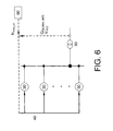
- FIG. 7 shows a diagram of the control method of the present invention in a preferred embodiment in the particular case in which the wind turbine is connected to the grid through a transformer 70, characterized in that it comprises a calculation block 8 of the wind farm grid voltage (V BUS ).
- V BUS wind farm grid voltage
- This calculation block 8 is based on a transformer model and, on the basis of voltage, current and power factor measurements (V, I, cos ) in the machine terminals it calculates the estimated grid voltage (V BUS_EST ) of the wind farm whereto the wind turbine is connected.
- V BUS_EST estimated voltage
- V BUS_REF grid voltage reference of the wind farm
- the voltage control is performed on a variable which is more representative of the voltage at the wind farm connection point (V PCC ) than of the terminal voltage of the machine (V), and is much less variable than the latter.
- each machine regulates the reactive power it generates according to a more similar voltage between all machines, yielding a voltage control with a better performance in terms of the grid.
- control system of the present embodiment includes a saturator element 9 which receives the set point of maximum reactive power (Q MAX ) and minimum reactive power (Q MIN ) as inputs so as not to exceed the permissible voltage limits.
- Said values are calculated in calculation block 8 based on the transformer model and voltage, current and power factor measurements (V, I, cos ⁇ ) at the machine terminals.
- This preferred embodiment allows a voltage control with similar characteristics to those of a two-level control (substation level and machine level), with the advantage of being performed locally on each wind turbine.
- a correction term of the blade pitch angle ( ⁇ ) is calculated in an element 15 according to the maximum active power that can be evacuated to the grid (P _MAX ) and the available mechanical power (P _MEC ), which depends on wind speed, rotational speed and blade pitch angle ( ⁇ ).
- the electrical power being generated at the moment before a sudden reduction in the maximum active power that can be evacuated to the grid is taken as an indicative value of the available mechanical power.
- the generator torque control takes into account the above correction of the blade pitch angle.
- Figure 8 shows a preferred embodiment of the correction angle ( ⁇ ) for different positions of the blade pitch angle ( ⁇ 1 , ⁇ 2 , ⁇ 3 , ⁇ 4 ), calculated on the basis of the difference ( ⁇ P) between the available mechanical power (P _MEC ) and the maximum power (P MAX ) it is possible to evacuate to the grid.
- a further object of the invention is a wind turbine comprising a rotor, a generator, a frequency converter, a control unit and means for connecting to the farm, so that said control unit is adjusted to implement a method according to any of the preceding claims.
- a further object of the invention is a method of controlling a wind farm consisting of at least two wind turbines such as those described and a wind farm communications network 40, characterized in that it comprises the following steps:
Applications Claiming Priority (2)
| Application Number | Priority Date | Filing Date | Title |
|---|---|---|---|
| ES200801706A ES2333393B1 (es) | 2008-06-06 | 2008-06-06 | Sistema y metodo de control de un aerogenerador. |
| PCT/ES2009/070200 WO2009147274A1 (es) | 2008-06-06 | 2009-06-03 | Método de control de un aerogenerador |
Publications (3)
| Publication Number | Publication Date |
|---|---|
| EP2317135A1 true EP2317135A1 (de) | 2011-05-04 |
| EP2317135A4 EP2317135A4 (de) | 2018-02-07 |
| EP2317135B1 EP2317135B1 (de) | 2020-08-05 |
Family
ID=41397760
Family Applications (1)
| Application Number | Title | Priority Date | Filing Date |
|---|---|---|---|
| EP09757653.2A Active EP2317135B1 (de) | 2008-06-06 | 2009-06-03 | Windturbinensteuerverfahren |
Country Status (5)
| Country | Link |
|---|---|
| US (1) | US8896142B2 (de) |
| EP (1) | EP2317135B1 (de) |
| DK (1) | DK2317135T3 (de) |
| ES (2) | ES2333393B1 (de) |
| WO (1) | WO2009147274A1 (de) |
Cited By (8)
| Publication number | Priority date | Publication date | Assignee | Title |
|---|---|---|---|---|
| EP2539584A2 (de) * | 2010-02-25 | 2013-01-02 | Vestas Wind Systems A/S | Windturbinensteuerung mit differenzialpolsteuerungsalgorithmus |
| CN102900602A (zh) * | 2011-07-27 | 2013-01-30 | 西门子公司 | 用于在电压限度内对风电场进行操作的方法和装置 |
| EP2757257A1 (de) * | 2013-01-22 | 2014-07-23 | Alstom Wind, S.L.U. | Verfahren und Vorrichtungen zum Regeln der Leistung von Generatoren |
| ES2491015R1 (es) * | 2012-09-28 | 2014-10-29 | Acciona Windpower, S.A. | Método de control de aerogenerador |
| EP2704282A3 (de) * | 2012-08-31 | 2017-07-26 | General Electric Company | Spannungsregelung für Windturbinengeneratoren |
| US10256759B2 (en) | 2014-09-02 | 2019-04-09 | Vestas Wind Systems A/S | Reactive power control system for a wind turbine generator |
| EP3649716A4 (de) * | 2017-07-06 | 2021-01-20 | General Electric Company | Zuweisung von reaktiver energieerzeugung für doppelt gespeistes induktionsgenerator-windturbinensystem |
| EP3996228A1 (de) * | 2020-11-04 | 2022-05-11 | Siemens Gamesa Renewable Energy Innovation & Technology S.L. | Steuerung des netzseitigen umrichter eines dgasm |
Families Citing this family (24)
| Publication number | Priority date | Publication date | Assignee | Title |
|---|---|---|---|---|
| DE102007021632A1 (de) * | 2007-05-09 | 2008-11-20 | Ssb-Antriebstechnik Gmbh & Co. Kg | Elektrischer Antrieb |
| CN102822509B (zh) * | 2010-02-25 | 2016-01-20 | 维斯塔斯风力系统集团公司 | 用于控制无功功率源的方法和控制装置 |
| US8432052B2 (en) * | 2010-05-27 | 2013-04-30 | Rockwell Automation Technologies, Inc. | Wind power converter system with grid side reactive power control |
| ES2410431B1 (es) * | 2010-06-04 | 2014-06-17 | Acciona Windpower, S.A. | Procedimiento para controlar la potencia activa generada por una central de generación distribuida; aerogenerador para llevar a cabo dicho procedimiento; y parque e�lico que comprende dicho aerogenerador |
| US8610306B2 (en) | 2011-07-29 | 2013-12-17 | General Electric Company | Power plant control system and method for influencing high voltage characteristics |
| GB2493711B (en) * | 2011-08-12 | 2018-04-25 | Openhydro Ip Ltd | Method and system for controlling hydroelectric turbines |
| DK2807743T3 (en) * | 2012-01-24 | 2016-04-04 | Senvion Gmbh | Wind park oversvingningsprediktor and method thereof |
| US9450409B2 (en) * | 2013-06-20 | 2016-09-20 | Abb Research Ltd. | Converter station power set point analysis system and method |
| US9425726B2 (en) * | 2013-06-25 | 2016-08-23 | Masdar Institute Of Science And Technology | Fault-tolerant wind energy conversion system |
| US9318988B2 (en) * | 2013-09-05 | 2016-04-19 | General Electric Company | System and method for voltage control of wind generators |
| EP2871743B1 (de) * | 2013-11-11 | 2017-08-30 | Siemens Aktiengesellschaft | Windkraftwerk, Windpark und Verfahren zum Betreiben |
| EP3149825B1 (de) * | 2014-05-28 | 2020-07-01 | GE Energy Power Conversion Technology Ltd | Reaktive leistungsvorhersagefähigkeit |
| CN104242314B (zh) * | 2014-08-26 | 2017-01-11 | 清华大学 | 一种风电场汇集区域电网电压安全域值的确定方法 |
| US10069331B2 (en) * | 2015-01-09 | 2018-09-04 | Generac Power Systems, Inc. | Load shed module |
| CN105098834B (zh) * | 2015-08-12 | 2018-02-13 | 国网山东省电力公司潍坊供电公司 | 一种用于双馈风电场的分工况分模式电压控制方法 |
| EP3200303B1 (de) * | 2016-01-29 | 2024-03-20 | Siemens Gamesa Renewable Energy A/S | Betreiben einer windturbine eines windparks |
| US10491038B2 (en) * | 2017-06-15 | 2019-11-26 | General Electric Company | Electrical power subsystems and methods for controlling same |
| KR101904102B1 (ko) * | 2017-06-28 | 2018-10-04 | 효성중공업 주식회사 | 정지형 동기 보상기(statcom)의 하이브리드 제어장치 |
| CN110080944B (zh) * | 2018-01-26 | 2021-09-24 | 通用电气公司 | 风力发电系统及其控制方法 |
| ES2937864T3 (es) * | 2019-04-03 | 2023-03-31 | Nordex Energy Se & Co Kg | Procedimiento para el funcionamiento de una instalación de energía eólica con al menos una pala de rotor de ángulo de paso de pala ajustable |
| CN111628528B (zh) * | 2020-06-22 | 2022-02-11 | 华北电力大学(保定) | 风电参与系统恢复的潮流越限消除方法及装置 |
| CN112653195B (zh) * | 2020-11-27 | 2022-10-14 | 国网甘肃省电力公司经济技术研究院 | 一种并网型微电网鲁棒优化容量配置方法 |
| US11641109B2 (en) | 2022-05-17 | 2023-05-02 | Zhejiang University | Grid-forming wind turbine control method for diode rectifier unit-based offshore wind power transmission system |
| CN114640141B (zh) * | 2022-05-17 | 2022-08-05 | 浙江大学 | 海上风电二极管整流单元送出系统的构网型风机控制方法 |
Family Cites Families (20)
| Publication number | Priority date | Publication date | Assignee | Title |
|---|---|---|---|---|
| US5083039B1 (en) * | 1991-02-01 | 1999-11-16 | Zond Energy Systems Inc | Variable speed wind turbine |
| US5798633A (en) * | 1996-07-26 | 1998-08-25 | General Electric Company | Battery energy storage power conditioning system |
| FR2801444B1 (fr) * | 1999-11-24 | 2002-02-08 | Dassault Aviat | Generateur electrique autonome, notamment pour aeronef |
| DE10059018C2 (de) | 2000-11-28 | 2002-10-24 | Aloys Wobben | Windenergieanlage bzw. Windpark bestehend aus einer Vielzahl von Windenergieanlagen |
| DE10136974A1 (de) | 2001-04-24 | 2002-11-21 | Aloys Wobben | Verfahren zum Betreiben einer Windenergieanlage |
| CA2460724C (en) | 2001-09-28 | 2013-03-12 | Aloys Wobben | Method for operating a wind park |
| US6921985B2 (en) | 2003-01-24 | 2005-07-26 | General Electric Company | Low voltage ride through for wind turbine generators |
| US7117070B2 (en) * | 2003-06-30 | 2006-10-03 | Rensselaer Polytechnic Institute | Power flow controller responsive to power circulation demand for optimizing power transfer |
| US7119452B2 (en) * | 2003-09-03 | 2006-10-10 | General Electric Company | Voltage control for wind generators |
| DE10344392A1 (de) | 2003-09-25 | 2005-06-02 | Repower Systems Ag | Windenergieanlage mit einem Blindleistungsmodul zur Netzstützung und Verfahren dazu |
| CN1926742B (zh) | 2004-03-12 | 2011-05-25 | 通用电气公司 | 用于操作发电机变频器的方法以及具有根据这种方法操作的发电机的风能涡轮机 |
| DE102004048341A1 (de) | 2004-10-01 | 2006-04-13 | Repower Systems Ag | Windpark mit robuster Blindleistungsregelung und Verfahren zum Betrieb |
| US7687937B2 (en) * | 2005-03-18 | 2010-03-30 | Wisconsin Alumni Research Foundation | Control of small distributed energy resources |
| EP1880459B2 (de) | 2005-05-13 | 2022-02-09 | Siemens Gamesa Renewable Energy A/S | Leistungssteuersystem eines windparks |
| US7372174B2 (en) * | 2005-11-11 | 2008-05-13 | Converteam Ltd | Power converters |
| KR100668118B1 (ko) * | 2005-12-30 | 2007-01-16 | 한국전기연구원 | 권선형 유도 발전기 제어용 전력변환장치 및 전력변환방법 |
| US7505833B2 (en) * | 2006-03-29 | 2009-03-17 | General Electric Company | System, method, and article of manufacture for controlling operation of an electrical power generation system |
| WO2008031433A1 (en) | 2006-09-14 | 2008-03-20 | Vestas Wind Systems A/S | Methods for controlling a wind turbine connected to the utility grid, wind turbine and wind park |
| US8577508B2 (en) * | 2007-05-04 | 2013-11-05 | University Of Alabama | Converter control of variable-speed wind turbines |
| KR100886194B1 (ko) * | 2007-06-08 | 2009-02-27 | 한국전기연구원 | 계통 연계형 고압 권선형 유도 발전기 제어 장치 |
-
2008
- 2008-06-06 ES ES200801706A patent/ES2333393B1/es not_active Expired - Fee Related
-
2009
- 2009-06-03 EP EP09757653.2A patent/EP2317135B1/de active Active
- 2009-06-03 US US12/996,046 patent/US8896142B2/en active Active
- 2009-06-03 ES ES09757653T patent/ES2841729T3/es active Active
- 2009-06-03 DK DK09757653.2T patent/DK2317135T3/da active
- 2009-06-03 WO PCT/ES2009/070200 patent/WO2009147274A1/es active Application Filing
Non-Patent Citations (1)
| Title |
|---|
| See references of WO2009147274A1 * |
Cited By (13)
| Publication number | Priority date | Publication date | Assignee | Title |
|---|---|---|---|---|
| EP2539584B1 (de) * | 2010-02-25 | 2023-06-07 | Vestas Wind Systems A/S | Windturbinensteuerung mit differenzialpolsteuerungsalgorithmus |
| EP2539584A2 (de) * | 2010-02-25 | 2013-01-02 | Vestas Wind Systems A/S | Windturbinensteuerung mit differenzialpolsteuerungsalgorithmus |
| CN102900602A (zh) * | 2011-07-27 | 2013-01-30 | 西门子公司 | 用于在电压限度内对风电场进行操作的方法和装置 |
| US9531193B2 (en) | 2011-07-27 | 2016-12-27 | Siemens Aktiengesellschaft | Method and arrangement for operating a wind farm within voltage limit |
| EP2704282A3 (de) * | 2012-08-31 | 2017-07-26 | General Electric Company | Spannungsregelung für Windturbinengeneratoren |
| ES2491015R1 (es) * | 2012-09-28 | 2014-10-29 | Acciona Windpower, S.A. | Método de control de aerogenerador |
| WO2014114648A1 (en) * | 2013-01-22 | 2014-07-31 | Alstom Renovables España, S.L. | Methods and arrangements for controlling power generators |
| US9793714B2 (en) | 2013-01-22 | 2017-10-17 | Alstom Renewable Technologies | Methods and arrangements for controlling power generators |
| EP2757257A1 (de) * | 2013-01-22 | 2014-07-23 | Alstom Wind, S.L.U. | Verfahren und Vorrichtungen zum Regeln der Leistung von Generatoren |
| US10256759B2 (en) | 2014-09-02 | 2019-04-09 | Vestas Wind Systems A/S | Reactive power control system for a wind turbine generator |
| EP3649716A4 (de) * | 2017-07-06 | 2021-01-20 | General Electric Company | Zuweisung von reaktiver energieerzeugung für doppelt gespeistes induktionsgenerator-windturbinensystem |
| EP3996228A1 (de) * | 2020-11-04 | 2022-05-11 | Siemens Gamesa Renewable Energy Innovation & Technology S.L. | Steuerung des netzseitigen umrichter eines dgasm |
| WO2022096427A1 (en) * | 2020-11-04 | 2022-05-12 | Siemens Gamesa Renewable Energy Innovation & Technology S.L. | Control of a dfig grid side converter |
Also Published As
| Publication number | Publication date |
|---|---|
| ES2333393A1 (es) | 2010-02-19 |
| EP2317135B1 (de) | 2020-08-05 |
| ES2841729T3 (es) | 2021-07-09 |
| DK2317135T3 (da) | 2020-11-09 |
| US8896142B2 (en) | 2014-11-25 |
| US20110156389A1 (en) | 2011-06-30 |
| WO2009147274A1 (es) | 2009-12-10 |
| EP2317135A4 (de) | 2018-02-07 |
| ES2333393B1 (es) | 2011-01-07 |
Similar Documents
| Publication | Publication Date | Title |
|---|---|---|
| US8896142B2 (en) | Wind turbine control method | |
| US10598701B2 (en) | Method for operating a power generation system | |
| US7679208B1 (en) | Apparatus and system for pitch angle control of wind turbine | |
| US8793027B2 (en) | Power curtailment of wind turbines | |
| AU2010273625B2 (en) | Bang-bang controller and control method for variable speed wind turbines during abnormal frequency conditions | |
| CN108475929B (zh) | 用于控制风力发电厂的方法 | |
| JP5156029B2 (ja) | 風力発電装置及びその制御方法 | |
| US9859710B2 (en) | Line impedance compensation system | |
| US9551323B2 (en) | Power plant control during a low voltage or a high voltage event | |
| JP5717916B2 (ja) | ウィンドファームの出力制御装置及び出力制御方法 | |
| US11098694B2 (en) | Method of controlling a wind turbine generator | |
| WO2019120404A1 (en) | Method of controlling a wind turbine generator | |
| EP2327878B1 (de) | Spitzensteuerungsvorrichtung und -system für einen windkraftgenerator | |
| John et al. | Voltage control and maximum power tracking of DFIG based wind power generator | |
| WO2023113801A1 (en) | System and method for decoupling current command components in a syncronously-rotating frame | |
| CN117269760A (zh) | 一种dfig精细化故障电流计算方法及系统 |
Legal Events
| Date | Code | Title | Description |
|---|---|---|---|
| PUAI | Public reference made under article 153(3) epc to a published international application that has entered the european phase |
Free format text: ORIGINAL CODE: 0009012 |
|
| 17P | Request for examination filed |
Effective date: 20101230 |
|
| AK | Designated contracting states |
Kind code of ref document: A1 Designated state(s): AT BE BG CH CY CZ DE DK EE ES FI FR GB GR HR HU IE IS IT LI LT LU LV MC MK MT NL NO PL PT RO SE SI SK TR |
|
| AX | Request for extension of the european patent |
Extension state: AL BA RS |
|
| DAX | Request for extension of the european patent (deleted) | ||
| RA4 | Supplementary search report drawn up and despatched (corrected) |
Effective date: 20180108 |
|
| RIC1 | Information provided on ipc code assigned before grant |
Ipc: F03D 9/25 20160101ALI20180102BHEP Ipc: H02P 9/42 20060101ALI20180102BHEP Ipc: F03D 9/00 20160101AFI20180102BHEP Ipc: H02P 9/48 20060101ALI20180102BHEP Ipc: H02J 3/38 20060101ALI20180102BHEP Ipc: H02J 3/18 20060101ALI20180102BHEP |
|
| GRAP | Despatch of communication of intention to grant a patent |
Free format text: ORIGINAL CODE: EPIDOSNIGR1 |
|
| STAA | Information on the status of an ep patent application or granted ep patent |
Free format text: STATUS: GRANT OF PATENT IS INTENDED |
|
| RIN1 | Information on inventor provided before grant (corrected) |
Inventor name: GARCIA SAYES, JOSE MIGUEL Inventor name: GARCIA BARACE, ALBERTO Inventor name: ROYO GARCIA, RICARDO Inventor name: NUNEZ POLO, MIGUEL Inventor name: ARLABAN GABEIRAS, TERESA Inventor name: ALONSO SADABA, OSCAR Inventor name: TONKS, STEPHEN Inventor name: HUARTE AMEZQUETA, ANA |
|
| INTG | Intention to grant announced |
Effective date: 20200323 |
|
| RAP1 | Party data changed (applicant data changed or rights of an application transferred) |
Owner name: NORDEX ENERGY SPAIN, S.A.U. |
|
| GRAS | Grant fee paid |
Free format text: ORIGINAL CODE: EPIDOSNIGR3 |
|
| GRAA | (expected) grant |
Free format text: ORIGINAL CODE: 0009210 |
|
| STAA | Information on the status of an ep patent application or granted ep patent |
Free format text: STATUS: THE PATENT HAS BEEN GRANTED |
|
| AK | Designated contracting states |
Kind code of ref document: B1 Designated state(s): AT BE BG CH CY CZ DE DK EE ES FI FR GB GR HR HU IE IS IT LI LT LU LV MC MK MT NL NO PL PT RO SE SI SK TR |
|
| REG | Reference to a national code |
Ref country code: GB Ref legal event code: FG4D |
|
| REG | Reference to a national code |
Ref country code: CH Ref legal event code: EP |
|
| REG | Reference to a national code |
Ref country code: AT Ref legal event code: REF Ref document number: 1299056 Country of ref document: AT Kind code of ref document: T Effective date: 20200815 |
|
| REG | Reference to a national code |
Ref country code: DE Ref legal event code: R096 Ref document number: 602009062554 Country of ref document: DE |
|
| REG | Reference to a national code |
Ref country code: IE Ref legal event code: FG4D |
|
| REG | Reference to a national code |
Ref country code: DK Ref legal event code: T3 Effective date: 20201103 |
|
| REG | Reference to a national code |
Ref country code: LT Ref legal event code: MG4D |
|
| REG | Reference to a national code |
Ref country code: NL Ref legal event code: MP Effective date: 20200805 |
|
| REG | Reference to a national code |
Ref country code: AT Ref legal event code: MK05 Ref document number: 1299056 Country of ref document: AT Kind code of ref document: T Effective date: 20200805 |
|
| PG25 | Lapsed in a contracting state [announced via postgrant information from national office to epo] |
Ref country code: NO Free format text: LAPSE BECAUSE OF FAILURE TO SUBMIT A TRANSLATION OF THE DESCRIPTION OR TO PAY THE FEE WITHIN THE PRESCRIBED TIME-LIMIT Effective date: 20201105 Ref country code: GR Free format text: LAPSE BECAUSE OF FAILURE TO SUBMIT A TRANSLATION OF THE DESCRIPTION OR TO PAY THE FEE WITHIN THE PRESCRIBED TIME-LIMIT Effective date: 20201106 Ref country code: AT Free format text: LAPSE BECAUSE OF FAILURE TO SUBMIT A TRANSLATION OF THE DESCRIPTION OR TO PAY THE FEE WITHIN THE PRESCRIBED TIME-LIMIT Effective date: 20200805 Ref country code: PT Free format text: LAPSE BECAUSE OF FAILURE TO SUBMIT A TRANSLATION OF THE DESCRIPTION OR TO PAY THE FEE WITHIN THE PRESCRIBED TIME-LIMIT Effective date: 20201207 Ref country code: LT Free format text: LAPSE BECAUSE OF FAILURE TO SUBMIT A TRANSLATION OF THE DESCRIPTION OR TO PAY THE FEE WITHIN THE PRESCRIBED TIME-LIMIT Effective date: 20200805 Ref country code: BG Free format text: LAPSE BECAUSE OF FAILURE TO SUBMIT A TRANSLATION OF THE DESCRIPTION OR TO PAY THE FEE WITHIN THE PRESCRIBED TIME-LIMIT Effective date: 20201105 Ref country code: FI Free format text: LAPSE BECAUSE OF FAILURE TO SUBMIT A TRANSLATION OF THE DESCRIPTION OR TO PAY THE FEE WITHIN THE PRESCRIBED TIME-LIMIT Effective date: 20200805 Ref country code: HR Free format text: LAPSE BECAUSE OF FAILURE TO SUBMIT A TRANSLATION OF THE DESCRIPTION OR TO PAY THE FEE WITHIN THE PRESCRIBED TIME-LIMIT Effective date: 20200805 Ref country code: SE Free format text: LAPSE BECAUSE OF FAILURE TO SUBMIT A TRANSLATION OF THE DESCRIPTION OR TO PAY THE FEE WITHIN THE PRESCRIBED TIME-LIMIT Effective date: 20200805 |
|
| PG25 | Lapsed in a contracting state [announced via postgrant information from national office to epo] |
Ref country code: LV Free format text: LAPSE BECAUSE OF FAILURE TO SUBMIT A TRANSLATION OF THE DESCRIPTION OR TO PAY THE FEE WITHIN THE PRESCRIBED TIME-LIMIT Effective date: 20200805 Ref country code: PL Free format text: LAPSE BECAUSE OF FAILURE TO SUBMIT A TRANSLATION OF THE DESCRIPTION OR TO PAY THE FEE WITHIN THE PRESCRIBED TIME-LIMIT Effective date: 20200805 Ref country code: NL Free format text: LAPSE BECAUSE OF FAILURE TO SUBMIT A TRANSLATION OF THE DESCRIPTION OR TO PAY THE FEE WITHIN THE PRESCRIBED TIME-LIMIT Effective date: 20200805 Ref country code: IS Free format text: LAPSE BECAUSE OF FAILURE TO SUBMIT A TRANSLATION OF THE DESCRIPTION OR TO PAY THE FEE WITHIN THE PRESCRIBED TIME-LIMIT Effective date: 20201205 |
|
| PG25 | Lapsed in a contracting state [announced via postgrant information from national office to epo] |
Ref country code: RO Free format text: LAPSE BECAUSE OF FAILURE TO SUBMIT A TRANSLATION OF THE DESCRIPTION OR TO PAY THE FEE WITHIN THE PRESCRIBED TIME-LIMIT Effective date: 20200805 Ref country code: CZ Free format text: LAPSE BECAUSE OF FAILURE TO SUBMIT A TRANSLATION OF THE DESCRIPTION OR TO PAY THE FEE WITHIN THE PRESCRIBED TIME-LIMIT Effective date: 20200805 Ref country code: EE Free format text: LAPSE BECAUSE OF FAILURE TO SUBMIT A TRANSLATION OF THE DESCRIPTION OR TO PAY THE FEE WITHIN THE PRESCRIBED TIME-LIMIT Effective date: 20200805 |
|
| REG | Reference to a national code |
Ref country code: DE Ref legal event code: R097 Ref document number: 602009062554 Country of ref document: DE |
|
| PLBE | No opposition filed within time limit |
Free format text: ORIGINAL CODE: 0009261 |
|
| STAA | Information on the status of an ep patent application or granted ep patent |
Free format text: STATUS: NO OPPOSITION FILED WITHIN TIME LIMIT |
|
| PG25 | Lapsed in a contracting state [announced via postgrant information from national office to epo] |
Ref country code: SK Free format text: LAPSE BECAUSE OF FAILURE TO SUBMIT A TRANSLATION OF THE DESCRIPTION OR TO PAY THE FEE WITHIN THE PRESCRIBED TIME-LIMIT Effective date: 20200805 |
|
| REG | Reference to a national code |
Ref country code: ES Ref legal event code: FG2A Ref document number: 2841729 Country of ref document: ES Kind code of ref document: T3 Effective date: 20210709 |
|
| 26N | No opposition filed |
Effective date: 20210507 |
|
| PG25 | Lapsed in a contracting state [announced via postgrant information from national office to epo] |
Ref country code: IT Free format text: LAPSE BECAUSE OF FAILURE TO SUBMIT A TRANSLATION OF THE DESCRIPTION OR TO PAY THE FEE WITHIN THE PRESCRIBED TIME-LIMIT Effective date: 20200805 |
|
| PG25 | Lapsed in a contracting state [announced via postgrant information from national office to epo] |
Ref country code: SI Free format text: LAPSE BECAUSE OF FAILURE TO SUBMIT A TRANSLATION OF THE DESCRIPTION OR TO PAY THE FEE WITHIN THE PRESCRIBED TIME-LIMIT Effective date: 20200805 |
|
| PG25 | Lapsed in a contracting state [announced via postgrant information from national office to epo] |
Ref country code: MC Free format text: LAPSE BECAUSE OF FAILURE TO SUBMIT A TRANSLATION OF THE DESCRIPTION OR TO PAY THE FEE WITHIN THE PRESCRIBED TIME-LIMIT Effective date: 20200805 |
|
| REG | Reference to a national code |
Ref country code: CH Ref legal event code: PL |
|
| GBPC | Gb: european patent ceased through non-payment of renewal fee |
Effective date: 20210603 |
|
| REG | Reference to a national code |
Ref country code: BE Ref legal event code: MM Effective date: 20210630 |
|
| PG25 | Lapsed in a contracting state [announced via postgrant information from national office to epo] |
Ref country code: LU Free format text: LAPSE BECAUSE OF NON-PAYMENT OF DUE FEES Effective date: 20210603 |
|
| PG25 | Lapsed in a contracting state [announced via postgrant information from national office to epo] |
Ref country code: LI Free format text: LAPSE BECAUSE OF NON-PAYMENT OF DUE FEES Effective date: 20210630 Ref country code: IE Free format text: LAPSE BECAUSE OF NON-PAYMENT OF DUE FEES Effective date: 20210603 Ref country code: GB Free format text: LAPSE BECAUSE OF NON-PAYMENT OF DUE FEES Effective date: 20210603 Ref country code: CH Free format text: LAPSE BECAUSE OF NON-PAYMENT OF DUE FEES Effective date: 20210630 |
|
| PG25 | Lapsed in a contracting state [announced via postgrant information from national office to epo] |
Ref country code: FR Free format text: LAPSE BECAUSE OF NON-PAYMENT OF DUE FEES Effective date: 20210630 |
|
| PG25 | Lapsed in a contracting state [announced via postgrant information from national office to epo] |
Ref country code: BE Free format text: LAPSE BECAUSE OF NON-PAYMENT OF DUE FEES Effective date: 20210630 |
|
| PG25 | Lapsed in a contracting state [announced via postgrant information from national office to epo] |
Ref country code: HU Free format text: LAPSE BECAUSE OF FAILURE TO SUBMIT A TRANSLATION OF THE DESCRIPTION OR TO PAY THE FEE WITHIN THE PRESCRIBED TIME-LIMIT; INVALID AB INITIO Effective date: 20090603 Ref country code: CY Free format text: LAPSE BECAUSE OF FAILURE TO SUBMIT A TRANSLATION OF THE DESCRIPTION OR TO PAY THE FEE WITHIN THE PRESCRIBED TIME-LIMIT Effective date: 20200805 |
|
| P01 | Opt-out of the competence of the unified patent court (upc) registered |
Effective date: 20230530 |
|
| PGFP | Annual fee paid to national office [announced via postgrant information from national office to epo] |
Ref country code: DK Payment date: 20230621 Year of fee payment: 15 Ref country code: DE Payment date: 20230620 Year of fee payment: 15 |
|
| PGFP | Annual fee paid to national office [announced via postgrant information from national office to epo] |
Ref country code: ES Payment date: 20230719 Year of fee payment: 15 |