EP2317103A2 - Control apparatus for engine - Google Patents
Control apparatus for engine Download PDFInfo
- Publication number
- EP2317103A2 EP2317103A2 EP10173933A EP10173933A EP2317103A2 EP 2317103 A2 EP2317103 A2 EP 2317103A2 EP 10173933 A EP10173933 A EP 10173933A EP 10173933 A EP10173933 A EP 10173933A EP 2317103 A2 EP2317103 A2 EP 2317103A2
- Authority
- EP
- European Patent Office
- Prior art keywords
- cylinder
- angular acceleration
- hos
- cylinders
- value
- Prior art date
- Legal status (The legal status is an assumption and is not a legal conclusion. Google has not performed a legal analysis and makes no representation as to the accuracy of the status listed.)
- Withdrawn
Links
Images


Classifications
-
- F—MECHANICAL ENGINEERING; LIGHTING; HEATING; WEAPONS; BLASTING
- F02—COMBUSTION ENGINES; HOT-GAS OR COMBUSTION-PRODUCT ENGINE PLANTS
- F02D—CONTROLLING COMBUSTION ENGINES
- F02D41/00—Electrical control of supply of combustible mixture or its constituents
- F02D41/008—Controlling each cylinder individually
- F02D41/0085—Balancing of cylinder outputs, e.g. speed, torque or air-fuel ratio
-
- F—MECHANICAL ENGINEERING; LIGHTING; HEATING; WEAPONS; BLASTING
- F02—COMBUSTION ENGINES; HOT-GAS OR COMBUSTION-PRODUCT ENGINE PLANTS
- F02D—CONTROLLING COMBUSTION ENGINES
- F02D13/00—Controlling the engine output power by varying inlet or exhaust valve operating characteristics, e.g. timing
- F02D13/02—Controlling the engine output power by varying inlet or exhaust valve operating characteristics, e.g. timing during engine operation
- F02D13/0223—Variable control of the intake valves only
- F02D13/0226—Variable control of the intake valves only changing valve lift or valve lift and timing
-
- F—MECHANICAL ENGINEERING; LIGHTING; HEATING; WEAPONS; BLASTING
- F02—COMBUSTION ENGINES; HOT-GAS OR COMBUSTION-PRODUCT ENGINE PLANTS
- F02D—CONTROLLING COMBUSTION ENGINES
- F02D41/00—Electrical control of supply of combustible mixture or its constituents
- F02D41/02—Circuit arrangements for generating control signals
- F02D41/14—Introducing closed-loop corrections
- F02D41/1497—With detection of the mechanical response of the engine
- F02D41/1498—With detection of the mechanical response of the engine measuring engine roughness
-
- F—MECHANICAL ENGINEERING; LIGHTING; HEATING; WEAPONS; BLASTING
- F02—COMBUSTION ENGINES; HOT-GAS OR COMBUSTION-PRODUCT ENGINE PLANTS
- F02B—INTERNAL-COMBUSTION PISTON ENGINES; COMBUSTION ENGINES IN GENERAL
- F02B75/00—Other engines
- F02B75/12—Other methods of operation
- F02B2075/125—Direct injection in the combustion chamber for spark ignition engines, i.e. not in pre-combustion chamber
-
- F—MECHANICAL ENGINEERING; LIGHTING; HEATING; WEAPONS; BLASTING
- F02—COMBUSTION ENGINES; HOT-GAS OR COMBUSTION-PRODUCT ENGINE PLANTS
- F02D—CONTROLLING COMBUSTION ENGINES
- F02D41/00—Electrical control of supply of combustible mixture or its constituents
- F02D41/0002—Controlling intake air
- F02D2041/001—Controlling intake air for engines with variable valve actuation
-
- F—MECHANICAL ENGINEERING; LIGHTING; HEATING; WEAPONS; BLASTING
- F02—COMBUSTION ENGINES; HOT-GAS OR COMBUSTION-PRODUCT ENGINE PLANTS
- F02D—CONTROLLING COMBUSTION ENGINES
- F02D2200/00—Input parameters for engine control
- F02D2200/02—Input parameters for engine control the parameters being related to the engine
- F02D2200/10—Parameters related to the engine output, e.g. engine torque or engine speed
- F02D2200/1012—Engine speed gradient
-
- F—MECHANICAL ENGINEERING; LIGHTING; HEATING; WEAPONS; BLASTING
- F02—COMBUSTION ENGINES; HOT-GAS OR COMBUSTION-PRODUCT ENGINE PLANTS
- F02D—CONTROLLING COMBUSTION ENGINES
- F02D41/00—Electrical control of supply of combustible mixture or its constituents
- F02D41/0002—Controlling intake air
-
- F—MECHANICAL ENGINEERING; LIGHTING; HEATING; WEAPONS; BLASTING
- F02—COMBUSTION ENGINES; HOT-GAS OR COMBUSTION-PRODUCT ENGINE PLANTS
- F02D—CONTROLLING COMBUSTION ENGINES
- F02D41/00—Electrical control of supply of combustible mixture or its constituents
- F02D41/30—Controlling fuel injection
- F02D41/38—Controlling fuel injection of the high pressure type
- F02D41/40—Controlling fuel injection of the high pressure type with means for controlling injection timing or duration
-
- F—MECHANICAL ENGINEERING; LIGHTING; HEATING; WEAPONS; BLASTING
- F02—COMBUSTION ENGINES; HOT-GAS OR COMBUSTION-PRODUCT ENGINE PLANTS
- F02M—SUPPLYING COMBUSTION ENGINES IN GENERAL WITH COMBUSTIBLE MIXTURES OR CONSTITUENTS THEREOF
- F02M26/00—Engine-pertinent apparatus for adding exhaust gases to combustion-air, main fuel or fuel-air mixture, e.g. by exhaust gas recirculation [EGR] systems
- F02M26/13—Arrangement or layout of EGR passages, e.g. in relation to specific engine parts or for incorporation of accessories
-
- F—MECHANICAL ENGINEERING; LIGHTING; HEATING; WEAPONS; BLASTING
- F02—COMBUSTION ENGINES; HOT-GAS OR COMBUSTION-PRODUCT ENGINE PLANTS
- F02P—IGNITION, OTHER THAN COMPRESSION IGNITION, FOR INTERNAL-COMBUSTION ENGINES; TESTING OF IGNITION TIMING IN COMPRESSION-IGNITION ENGINES
- F02P5/00—Advancing or retarding ignition; Control therefor
- F02P5/04—Advancing or retarding ignition; Control therefor automatically, as a function of the working conditions of the engine or vehicle or of the atmospheric conditions
- F02P5/145—Advancing or retarding ignition; Control therefor automatically, as a function of the working conditions of the engine or vehicle or of the atmospheric conditions using electrical means
- F02P5/15—Digital data processing
- F02P5/1502—Digital data processing using one central computing unit
- F02P5/1512—Digital data processing using one central computing unit with particular means concerning an individual cylinder
-
- Y—GENERAL TAGGING OF NEW TECHNOLOGICAL DEVELOPMENTS; GENERAL TAGGING OF CROSS-SECTIONAL TECHNOLOGIES SPANNING OVER SEVERAL SECTIONS OF THE IPC; TECHNICAL SUBJECTS COVERED BY FORMER USPC CROSS-REFERENCE ART COLLECTIONS [XRACs] AND DIGESTS
- Y02—TECHNOLOGIES OR APPLICATIONS FOR MITIGATION OR ADAPTATION AGAINST CLIMATE CHANGE
- Y02T—CLIMATE CHANGE MITIGATION TECHNOLOGIES RELATED TO TRANSPORTATION
- Y02T10/00—Road transport of goods or passengers
- Y02T10/10—Internal combustion engine [ICE] based vehicles
- Y02T10/12—Improving ICE efficiencies
Definitions
- This invention relates to an apparatus for controlling an internal combustion engine, and more particularly to a control apparatus capable of detecting and correcting both the dispersion of the torques and the dispersion of the air/fuel ratios, with respect to the respective cylinders.
- JP-A-2004-52620 discloses an invention according to which the dispersion of the intake air amounts for the respective cylinders is detected/corrected by the air-flow sensor and then the dispersion of the air/fuel (A/F) ratios (i.e. fuel injection amounts) for the respective cylinders is detected/corrected by the air/fuel ratio sensor.
- A/F air/fuel
- the intake air flow sensor is disposed apart from the combustion chamber, and therefore such components as an air intake pipe and a throttle that actually dilute the information on the intake air amount for each cylinder, are located between them. Thus, a certain precision deterioration occurs in detecting the intake air amount for each cylinder by the intake air flow sensor. Since the air/fuel ratio sensor is also disposed usually in the exhaust manifold, the air/fuel ratio sensor is located apart from the combustion chamber. Hence, the information on the air/fuel ratio contained in the signal detected by the air/fuel ratio sensor is diluted especially in the operating range of engine where the rotational speed and the fuel flow rate are both low.
- a unit i.e. control apparatus for detecting/correcting the dispersion of the air/fuel ratios and the dispersion of the torques, with respect to the respective cylinders with high precision for a short period of time.
- Fig. 1 schematically shows an engine control apparatus comprising a unit 161 for calculating a mean value of the angular acceleration with respect to each cylinder; a unit 162 for calculating the dispersion of the angular acceleration with respect to each cylinder; a unit 163 for estimating the torque and the air/fuel ratio, with respect to each cylinder on the basis of the calculated mean and the calculated dispersion; and/or a unit 164 for controlling at least one of the intake air amount, the fuel injection amount and the ignition timing, with respect to each cylinder on the basis of the estimated torque and the estimated air/fuel ratio.
- the generated torque becomes unstable (with increased dispersion). If the intake air amount for one of the cylinders becomes larger than the target intake air amount, the torque generated as a result of the fuel combustion in that cylinder remains almost the same (as the fuel injection amount is invariable), but the air/fuel ratio for the cylinder becomes lean. Accordingly, the generated torque becomes unstable (with increased dispersion).
- both the fuel injection amount and the intake air amount, for one of the cylinders become smaller than their target values, the torque generated as a result of fuel combustion in that cylinder decreases. Since the air/fuel ratio for that cylinder remains almost invariable, the torque does not become unstable (with non-increasing dispersion).
- both of the fuel injection amount and the intake air amount, for one of the cylinders become greater than their target values, the torque generated as a result of fuel combustion in that cylinder increases. Since the air/fuel ratio remains almost invariable, the torque does not become unstable (with non-increasing dispersion).
- the torque correction control through the control of the ignition timing is performed as needed if, for example, the intake air amounts for the respective cylinders cannot be controlled individually.
- the angular accelerations with respect to the respective cylinders should be obtained, in synchronism with the fuel combustion cycles of the respective cylinders, from the signals derived from such sensors capable of obtaining the information on the engine shaft angular position as the crankshaft angular position sensor and the camshaft angular position sensor.
- Fig. 2 schematically shows a unit for controlling at least one of the intake air amount, the fuel injection amount and the ignition timing, with respect to each cylinder on the basis of the estimated torque and the estimated air/fuel ratio with respect to each cylinder, in such a manner that the differences among the estimated torques and the estimated air/fuel ratios with respect to the respective cylinders become small.
- the control of the intake air amount, the fuel injection amount and the ignition timing with respect to each cylinder are so performed, as one of the functions described with Fig. 1 , as to make the differences among the torques and the differences among the air/fuel ratios, with respect to the respective cylinders as small as possible.
- Fig. 3 schematically shows an engine control apparatus wherein the unit 163 for estimating the torque and the air/fuel ratio of each cylinder specifies that cylinder of which the mean of angular acceleration is minimum, and judges that the torque of the specified cylinder is smaller than the torques of any other cylinders and that the air/fuel ratio of the specified cylinder is comparable with the air/fuel ratios of all the other cylinders, when a mean value of the angular acceleration of the specified cylinder is not greater than the predetermined value A1 1nd the dispersion of the angular acceleration of the specified cylinder is smaller than the predetermined value B1.
- the torque with respect to the cylinder having the smallest mean of angular acceleration is considered smaller than the torque of any other cylinder.
- the air/fuel ratio with respect to that cylinder is considered comparable with the air/fuel ratios with respect to all other cylinders. In this case, it is judged that both the fuel injection amount and the intake air amount, with respect to the cylinder decreased.
- Fig. 4 schematically shows an engine control apparatus wherein the unit 163 for estimating the torque and the air/fuel ratio of each cylinder specifies the cylinder of which the mean of angular acceleration is minimum, and judges that the torque of the specified cylinder is smaller than the torques of any other cylinders and that the air/fuel ratio of the specified cylinder is lean as compared with the air/fuel ratios of all the other cylinders, when a mean value of the angular acceleration of the specified cylinder is not greater than the predetermined value A1 and the dispersion of the angular acceleration of the specified cylinder is not smaller than the predetermined value B 1.
- the torque of the cylinder having the smallest mean of angular acceleration is considered smaller than the torque of any other cylinder.
- the air/fuel ratio of that cylinder is considered lean as compared with the air/fuel ratios of all the other cylinders. In this case, it is judged that the fuel injection amount of the cylinder decreases, and the intake air amount of the cylinder is invariant or increases.
- Fig. 5 schematically shows an engine control apparatus wherein the unit 163 for estimating the torque and the air/fuel ratio of each cylinder specifies the cylinder of which the mean of angular acceleration is maximum, and judges that the torque of the specified cylinder is greater than the torques of any other cylinders and that the air/fuel ratio of the specified cylinder is comparable with or rich as compared with, the air/fuel ratios of all the other cylinders, when a mean value of the angular acceleration of the specified cylinder is not smaller than the predetermined value A2 and the dispersion of the angular acceleration of the specified cylinder is smaller than the predetermined value B 1.
- the torque of the cylinder having the greatest mean of angular acceleration is considered greater than the torque of any other cylinder.
- the air/fuel ratio of that cylinder is considered comparable with or rich as compared with, the air/fuel ratios of all the other cylinders. In this case, it is judged that the fuel injection amount of the cylinder increases (with the intake air amount invariable), or the intake air amount of the cylinder decreases (with the fuel injection amount invariable).
- Fig. 6 schematically shows an engine control apparatus wherein the unit 163 for estimating the torque and the air/fuel ratio of each cylinder specifies the cylinder of which the dispersion of angular acceleration is maximum, and judges that the torque of the specified cylinder is comparable with the torques of any other cylinders and that the air/fuel ratio of the specified cylinder is lean as compared with the air/fuel ratios of all the other cylinders, when a mean value of the angular acceleration of the specified cylinder is greater than the predetermined value A1 and smaller than the predetermined value A2 and the dispersion of the angular acceleration of the specified cylinder is not smaller than the predetermined value B1.
- a mean value of the angular acceleration of one of the cylinders is not largely different from the angular acceleration of any other cylinder, the torque of that cylinder is considered nearly equal to the torque of any other cylinder. If the dispersion of the angular acceleration of one of the cylinders is large, the air/fuel ratio of that cylinder is considered lean as compared with the air/fuel ratios of all the other cylinders. In this case, it is judged that the fuel injection amount of the cylinder remains invariable and the intake air amount of the cylinder increases.
- Fig. 7 schematically shows an engine control apparatus wherein the predetermined value A1 is smaller than a mean value of the angular accelerations of all the cylinders during a predetermined period of time.
- the predetermined value A1 is chosen as the threshold for angular acceleration that is used to locate a cylinder whose torque is smaller than the torques of all the other cylinders. Therefore, the predetermined value A1 is set smaller than a mean value of the angular accelerations of all the cylinders.
- Fig. 8 schematically shows an engine control apparatus wherein the predetermined value A2 is greater than a mean value of the angular accelerations of all the cylinders during the predetermined period of time.
- the predetermined value A2 is chosen as the threshold for angular acceleration that is used to locate a cylinder whose torque is greater than the torques of any other cylinders. Therefore, the predetermined value A2 is set greater than a mean value of the angular accelerations of all the cylinders.
- Fig. 9 schematically shows an engine control apparatus wherein the predetermined value A1 is negative and the predetermined value A2 is positive when the engine is idling.
- the value A1 chosen as the threshold for angular acceleration that is used to locate a cylinder whose torque is smaller than the torques of any other cylinders is set negative whereas the value A2 chosen as the threshold for angular acceleration that is used to locate a cylinder whose torque is greater than the torques of any other cylinders, is set positive.
- Fig. 10 schematically shows an engine control apparatus wherein the dispersion of the angular acceleration of each cylinder is represented by the standard deviation or the variance, of the acceleration of that particular cylinder.
- the standard deviation or the variance is introduced as the general index of indicating the dispersion.
- Fig. 11 schematically shows an engine control apparatus wherein the dispersion of the angular acceleration of each of the cylinders is calculated by applying the weighted moving average method to the square of the absolute value of the angular acceleration of that cylinder, or by applying the weighted moving average method to the absolute value of the angular acceleration of that cylinder.
- the variance or the standard deviation is known as the index of indicating the dispersion, they are not suitable for on-board successive calculation. Therefore, the variance is approximately calculated by using the value, which is suitable for on-board successive calculation, obtained through the application of the weighted moving average method to the square of the absolute value of the angular acceleration of each cylinder, or the standard deviation is approximately calculated by using the value, which is suitable for on-board successive calculation, obtained through the application of the weighted moving average method to the absolute value of the angular acceleration of each cylinder.
- Fig. 12 schematically shows an engine control apparatus wherein the intake air amount of the specific cylinder the torque of which is judged smaller than those of any other cylinders and the air/fuel ratio of which is judged comparable with those of all the other cylinders, is corrected and increased until a mean value of the angular acceleration of the specific cylinder becomes greater than the predetermined value A1; and the fuel injection amount of the specific cylinder is also corrected and increased so as to keep the air/fuel ratio of the specific cylinder in accordance with the increased intake air amount.
- Fig. 13 schematically shows an engine control apparatus wherein the fuel injection amount of the specific cylinder the torque of which is judged smaller than those of any other cylinders and the air/fuel ratio of which is judged lean as compared with those of all the other cylinders, is corrected and increased until a mean value of the angular acceleration of the specific cylinder becomes greater than the predetermined value A1 and until the dispersion of the angular acceleration of the specific cylinder becomes smaller than the predetermined value B1.
- the intake air amount of the specific cylinder is corrected and increased until a mean value of the angular acceleration of the specific cylinder becomes greater than the predetermined value A1 (that is, until the decrease in the torque of the specific cylinder ceases) and until the dispersion of the angular acceleration of the specific cylinder becomes smaller than the predetermined value B1 (that is, until the air/fuel ratio of the specific cylinder ceases becoming lean).
- Fig. 14 schematically shows an engine control apparatus wherein the fuel injection amount of the specific cylinder the torque of which is judged greater than those of any other cylinders and the air/fuel ratio of which is judged comparable with or rich as compared with, those of all the other cylinders, is corrected and decreased until a mean value of the angular acceleration of the specific cylinder becomes smaller than the predetermined value A2.
- the fuel injection amount of the specific cylinder is corrected and decreased until a mean value of the angular acceleration of the specific cylinder becomes smaller than the predetermined value A2 (that is, until the increase in the torque of the specific cylinder ceases).
- Fig. 15 schematically shows an engine control apparatus wherein the intake air amount of the specific cylinder the torque of which is judged comparable with those of all the other cylinders and the air/fuel ratio of which is judged leaner than those of any other cylinders, is corrected and decreased until the dispersion of the angular acceleration of the specific cylinder becomes smaller than the predetermined value B1.
- the intake air amount of the specific cylinder is corrected and decreased until the dispersion of the angular acceleration of the specific cylinder becomes smaller than the predetermined value B1 (that is, until the air/fuel ratio of the specific cylinder ceases becoming lean).
- Fig. 16 schematically shows an engine control apparatus wherein the ignition timing of the specific cylinder the torque of which is judged smaller than those of any other cylinders and the air/fuel ratio of which is judged comparable with those of all the other cylinders, is corrected and advanced in angle until a mean value of the angular acceleration of the specific cylinder becomes greater than the predetermined value A1.
- Fig. 17 schematically shows an engine control apparatus wherein the ignition timing of the specific cylinder the torque of which is judged greater than those of any other cylinders and the air/fuel ratio of which is judged comparable with or rich as compared with, those of all the other cylinders, is corrected and retarded in angle until a mean value of the angular acceleration of the specific cylinder becomes smaller than the predetermined value A2.
- the torque of which is judged greater than those of any other cylinders and the air/fuel ratio of which is judged comparable with or rich as compared with, those of all the other cylinders, it is considered that the fuel injection amount of the specific cylinder increased (with the intake air amount invariable) or the intake air amount of the specific cylinder decreased (with the fuel injection amount invariable).
- the torque can also be decreased by correcting and retarding in angle the ignition timing of the specific cylinder.
- Fig. 18 schematically shows an engine control apparatus wherein the specific cylinder with respect to which a mean value of the angular acceleration is minimum, is preferentially located; and when a mean value of the angular acceleration of the specific cylinder is not greater than the predetermined value A1 and when the dispersion of the angular acceleration of the specific cylinder is not smaller than the predetermined value B1, the fuel injection amount of the specific cylinder is preferentially corrected and increased until the mean becomes greater than A1 and until the dispersion becomes smaller than B1.
- the torque of the cylinder of which a mean value of the angular acceleration is minimum is judged smaller than those of any other cylinders. Also, if the dispersion of the angular acceleration of the specific cylinder is great, the air/fuel ratio of the specific cylinder is judged lean as compared with those of all the other cylinders.
- the cylinder the torque of which is smaller than those of any other cylinders and the air/fuel ratio of which is judged lean as compared with those of all the other cylinders, is the most unstable cylinder. Accordingly, the most unstable cylinder is preferentially located and the fuel injection amount of the most unstable cylinder is preferentially corrected and increased.
- Fig. 19 schematically shows an engine control apparatus wherein the mean value of the fuel injection amount correction values for all the cylinders is calculated, and the final fuel injection amount correction value for one of the cylinders is obtained by subtracting the mean from the fuel injection amount correction value for that cylinder.
- the fuel injection amount for one of the cylinders is corrected, and increased or decreased at a time, and this process is successively repeated for all the cylinders.
- the DC component of the fuel injection amount correction value i.e. mean of the fuel injection amount correction values for all the cylinders
- the mean of the fuel injection amounts for all the cylinders is calculated, and the final fuel injection amount correction value for one of the cylinders is obtained by subtracting the mean from the fuel injection amount correction value for that cylinder.
- Fig. 20 schematically shows an engine control apparatus wherein the mean value of the intake air amount correction values for all the cylinders is calculated, and the final intake air amount correction value for one of the cylinders is obtained by subtracting the mean from the intake air amount correction value for that cylinder.
- the intake air amount for one of the cylinders is corrected, and increased or decreased, and this process is successively repeated for all the cylinder.
- the mean of the intake air amount correction values for all the cylinders is calculated, and the final intake air amount correction value for one of the cylinders is obtained by subtracting the mean from the intake air amount correction value for that cylinder.
- Fig. 21 schematically shows an engine control apparatus wherein the mean value of the ignition timing correction values for all the cylinders is calculated, and the final ignition timing correction value for one of the cylinders is obtained by subtracting the mean from the ignition timing correction value for that cylinder.
- the ignition timing for one of the cylinders is corrected, and advanced or retarded in angle, and this process is successively repeated for all the cylinders.
- the mean of the ignition timing correction values for all the cylinders is calculated, and the final ignition timing correction value for one of the cylinders is obtained by subtracting the mean from the ignition timing correction value for that cylinder.
- a single stage of correction does not necessarily complete the correction of errors in the fuel injection amount and the intake air amount. For example, if both the fuel injection amount and the intake air amount are deviated from the target value in such a manner that they tend to increase, the fuel injection amount is first corrected and decreased in accordance with the procedure described with Fig. 14 until the increase in torque is canceled. Since the intake air amount is not corrected and decreased in this case, the air/fuel ratio becomes lean. Then, the intake air amount is corrected and decreased in accordance with the procedure described with Fig. 15 so that the fuel injection amount and the intake air amount are properly corrected through this two stage correction procedure. The same effect can be obtained in some other cases.
- the cylinder for which either the fuel injection amount or the intake air amount is erroneous can be located quickly (i.e. located before both of them become erroneous).
- the three cases (1) superfluous fuel amount, (2) meager fuel amount, (3) superfluous intake air amount
- the three cases (1) superfluous fuel amount, (2) meager fuel amount, (3) superfluous intake air amount
- the errors can be corrected through a two-stage location/correction procedure.
- the dispersions of the air/fuel ratios and the torques, with respect to the respective cylinders can be detected and corrected with high precision and for a short period of time.
- the intake air amount, the fuel injection amount and the ignition timing of each cylinder are properly corrected in such a manner that the differences among the torques and the air/fuel ratios of the respective cylinders become small, the performance of the engine whose structure is ever becoming complicated can be long secured in practical environments, and therefore exhaust gas, CO 2 and fuel cost can be prevented from increasing.
- the engine control apparatus wherein the ignition timing of the specific cylinder the torque of which is judged smaller than those of any other cylinders and the air/fuel ratio of which is judged comparable with those of all the other cylinders, is corrected and advanced in angle until a mean value of the angular acceleration of the specific cylinder becomes greater than the predetermined value A1.
- the engine control apparatus wherein the ignition timing of the specific cylinder the torque of which is judged greater than those of any other cylinders and the air/fuel ratio of which is judged comparable with or rich as compared with, those of all the other cylinders, is corrected and retarded in angle until a mean value of the angular acceleration of the specific cylinder becomes smaller than the predetermined value A2.
- the engine control apparatus wherein the specific cylinder with respect to which a mean value of the angular acceleration is minimum, is preferentially located; and when a mean value of the angular acceleration of the specific cylinder is not greater than the predetermined value A1 and when the dispersion of the angular acceleration of the specific cylinder is not smaller than the predetermined value B1, the fuel injection amount of the specific cylinder is preferentially corrected and increased until the mean becomes greater than A1 and until the dispersion becomes smaller than B 1.
- the engine control apparatus wherein the mean of the fuel injection amount correction values for all the cylinders is calculated, and the final fuel injection amount correction value for one of the cylinders is obtained by subtracting the mean from the fuel injection amount correction value for that cylinder.
- the engine control apparatus wherein the mean of the intake air amount correction values for all the cylinders is calculated, and the final intake air amount correction value for one of the cylinders is obtained by subtracting the mean from the intake air amount correction value for that cylinder.
- the engine control apparatus wherein the mean of the ignition timing correction values for all the cylinders is calculated, and the final ignition timing correction value for one of the cylinders is obtained by subtracting the mean from the ignition timing correction value for that cylinder.
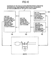
- Fig. 22 schematically shows a system for controlling an engine according to an embodiment of this invention.
- a multiple-cylinder engine 9 e.g. four-cylinder engine in this embodiment
- ambient air flows into a cylinder through an air cleaner 1 via an intake manifold 4 and a collector 5.
- the flow rate of the intake air is detected by an air-flow sensor 2 and then adjusted by an electronic throttle 3.
- the temperature of the intake air is detected by an intake-air temperature sensor 29.
- a crank angle sensor 15 outputs a signal generated every 10 degrees of the rotation of the crankshaft and a signal generated every combustion cycle.
- a water temperature sensor 14 detects the temperature of the engine coolant.
- An accelerator depression sensor 13 detects the degree of the actuation of the accelerator 6 so as to detect the torque demanded by the driver.
- the signals outputted from the accelerator depression sensor 13, the air-flow sensor 2, the intake-air temperature sensor 29, a throttle aperture sensor 17 attached to the electronic throttle 3, the crank angle sensor 15, and the water temperature sensor 14, are delivered to a control unit 16 which, described in detail later, determines the operating condition of the engine 9 on the basis of those signals and calculates the optimal values of the main manipulated variables for engine operation such as intake-air amount, fuel injection amount and ignition timing.
- the target intake air amount calculated by the control unit 16 is converted to a signal for determining the target throttle aperture and further to a signal which is sent to the electronic throttle 3 to drive the same.
- the fuel injection amount is converted to a valve-opening signal, which is sent to a fuel injector 7.
- To the ignition plug 8 is applied a signal for firing the plug 8 in synchronism with the timing calculated by the control unit 16.
- the injected fuel is mixed with the air flowing into the cylinder of the engine 9 through the intake manifold so that air-fuel mixture is formed in the cylinder 9.
- the air-fuel mixture is explosively combusted by being ignited with sparks generated by the spark plug 8 in accordance with a predetermined timing, and the pressure of explosion pushes the piston to generate the motive force of the engine.
- exhaust gas is sent to a 3-way catalyst 11 via an exhaust manifold 10. Part of the exhaust gas is returned to the intake manifold 4 through an exhaust gas recirculation pipe 18.
- the amount of the recirculated exhaust gas is controlled by an exhaust gas recirculation (EGR) control valve 19.
- EGR exhaust gas recirculation
- a catalyst-upstream A/F sensor 12 is disposed between the engine 9 and the 3-way catalyst 11 whereas a catalyst-downstream O 2 sensor 20 is disposed downstream of the 3-way catalyst 11.
- Fig. 23 shows in block diagram the internal structure of the control unit 16.
- the control unit (ECU) 16 receives the outputs of the air-flow sensor 2, the catalyst- upstream A/F sensor 12, the accelerator depression sensor 13, the water temperature sensor 14, a crank angle sensor 15, the throttle aperture sensor 17, the catalyst-downstream O 2 sensor 20, the intake-air temperature sensor 29, and a vehicle speed sensor 31. These signals are initially processed by an input circuit 24 so as to remove noise, and then sent to an input/output port 25. The values received by the input/output port 25 are stored in a RAM 23 and subjected to calculation in CPU 21. The control program which executes the algorithm of the calculation is previously written in a ROM 22.
- the values that have been calculated according to the control program and that represent the actuating signals for actuating the respective control elements (or actuators), are stored in the RAM 23 and then sent to the input/output port 25.
- the actuating signal for the ignition plug is an ON/OFF signal which appears when the primary coil of the ignition output circuit draws current, and disappears when the current through the primary coil is interrupted. The instant at which ignition takes place occurs in response to the transition of the actuating signal from ON-state to OFF-state.
- the signal for firing the ignition plug, which has been set in the output port, is amplified by an ignition signal output circuit 26 to such an extent that it has energy enough to fire the plug, before it is supplied to the plug.
- the actuation signal for the fuel injector is also an ON/OFF signal that appears when fuel is to be injected and disappears when fuel is not to be injected. This signal is sent to the fuel injector 7 after it has been amplified by a fuel injector drive circuit 27 to such an extent that it has energy enough to actuate the fuel injector 7.
- the actuating signal for setting the target aperture of the electronic throttle 3 is sent to the electronic throttle 3 via an electronic throttle drive circuit 28.
- the actuating signal for setting the target lift of a variable intake valve 30 and the target instant for opening or closing the valve 30, is sent to the variable intake valve 30 via a variable intake valve drive circuit 32.
- FIG. 24 shows in block diagram the entire control system, which comprises:
- the “basic fuel injection amount calculation section” calculates the basic fuel injection amount (Tp0).
- the “control permission flag calculation section” calculates the flag (fp_seigyo) for permitting the execution of the correction of fuel injection amount and intake air amount for each cylinder.
- the "per-cylinder angular acceleration characteristic calculation section” calculates the mean (M_omega_n (n: cylinder number)) of the angular acceleration of each cylinder and the variance (V_omega_n (n: cylinder number)) of the angular acceleration of each cylinder, representative of the angular acceleration characteristics of each cylinder, when the control permmission is issued.
- the "correction-applicable cylinder and correction direction detection section” calculates, on the basis of the above mentioned angular acceleration characteristics, the cylinder numbers (Cyl_hos) of the correction-applicable cylinders; the correction direction (Dir_hos_F) of whether the fuel injection amount for each correction-applicable cylinder is to be increased or decreased; the correction direction (Dir_hos_A) of whether the intake air amount for each correction-applicable cylinder is to be increased or decreased; the mean (M_omega_Cyl_hos) of the angular acceleration with respect to the correction-applicable cylinder; and the variace (V_omega_Cyl_hos) of the angular acceleration with respect to the correction-applicable cylinder.
- the "per-cylinder fuel injection amount correction value calculation section” calculates the fuel injection amount correction value (F_hos_n (n: cylinder number)) for each cylinder on the basis of the various parameters calculated by the correction-applicable cylinder and correction direction detection section.
- the "per-cylinder intake air amount correction value calculation section” calculates the intake air amount correction value (IVO_hos_n, IVC_hos_n) for each cylinder on the basis of the various parameters calculated by the correction-applicable cylinder and correction direction detection section.
- (IVO_hos_n) is the correction value applied to the opening instant (IVO_n) of the fuel injector of the number "n” cylinder
- (IVC_hos_n) is the correction value applied to the closing instant (IVC_n) of the fuel injector of the number "n” cylinder.
- This calculation section calculates the basic fuel injection amount (Tp0). To be concrete, it is calculated by using the expression shown in Fig. 25 . In that expression, Cyl denotes the number of cylinders, and K0 is determined on the basis of the specification (i.e. relationship between fuel injection pulse width and fuel injection amount) of the injectors associated with the cylinders.
- This calculation section calculates the control permission flag (fp_seigyo).
- the flow of calculation is as shown in Fig. 26 .
- the execution of control is permitted if the difference ( ⁇ Apo) between the present and previous values of accelerator depression remains within a predetermined range for a predetermined period of time, if the difference ( ⁇ Tp0) between the present and previous values of the basic fuel injection amount remains within a predetermined range for a predetermined period of time, and if the difference ( ⁇ Ne) between the present and previous values of engine rotational speed remains within a predetermined range for a predetermined period of time.
- This calculation section calculates the mean (M_omega_n (n: cylinder number)) of the angular acceleration of one of the cylinders representative of the angular acceleration characteristic of that cylinder, and the variance (V_omega_n (n: cylinder number)) of the angular acceleration of one of the cylinders.
- the flow of calculation is as shown in Fig. 27 .
- the angular acceleration (omega_n) of the n-th cylinder is obtained from the engine rotational speed (Ne).
- the mean of Ne's is calculated every combustion cycle; the difference between the mean and previous value of Ne is termed (omega_n); and the mean (M_omega_n) of the angular acceleration of the n-th cylinder over a predetermined number of cycles is derived from (omega_n).
- the variance (V_omega_n) of the angular acceleration of the n-th cylinder over a predetermined number of cycles is also derived from (omega_n).
- This calculation section consists of a "section for calculating both the information on the cylinder of which the mean of angular acceleration is minimum/maximum and the information on the cylinder of which the variance of angular acceleration is maximum "and a "correction-applicable cylinder and correction direction detection section 2".
- the details of the respective calculation sections will be described in the following.
- This calculation section calculates both the information on the cylinder of which the mean of angular acceleration is minimum/maximum and the information on the cylinder of which the variance of angular acceleration is maximum. The details are shown in Fig. 29 :
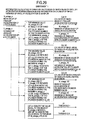
- This detection section detects the correction-applicable cylinders and the correction directions. The details are shown in Fig. 30 .
- Condition 1 is not satisfied, and A1 ⁇ M_omega_K3 ⁇ A2, and V_omega_K3 ⁇ B1.
- Cyl_hos Cyl_K1
- Dir_hos_F 1
- Dir_hos_A 0
- M_omega_cyl_hos M_omega_K1
- V_ omega_cyl_hos V_omega_K1.
- Cyl_hos Cyl_K3
- Cyl_hos Cyl_K2
- Dir_hos_F -1
- This calculation section calculates the fuel injection amount correction value (F_hos_n) for each cylinder.
- the details are shown in Fig. 31 : the fuel injection amount correction value (F_hos_n) for the cylinder with the cylinder number of Cyl_hos is calculated as follows.
- the renewed value (F_hos_1) of increased fuel injection amount is obtained from M_omega_Cyl_hos by referring to the table value (Tbl_F_hos_1).
- the renewed value (F_hos_0) of decreased fuel injection amount is obtained from M_omega_Cyl_hos by referring to the table value (Tb1_F_hos_0).
- the values obtained by referring to the table are determined depending on how much fuel injection amount should be corrected per one renewal with respect to the magnitude (decreased or increased amount) of a mean value of the angular acceleration.
- This calculation section calculates the intake air amount correction value (Tp_hos_n) for each cylinder.
- the details are shown in Fig. 32 : the intake air amount correction value (Tp_hos_n) for the cylinder with the cylinder number of Cyl_hos is calculated as follows.
- the renewed value (Tp hos - 1) of increased intake air amount is obtained from M_omega_Cyl_hos by referring to the table value (Tb1_Tp_hos_1).
- the renewed value (Tp_hos_0) of decreased intake air amount is obtained from V_omega_Cyl_hos by referring to the table value (Tb1_Tp_hos_0).
- the values obtained by referring to the table are determined depending on how much intake air amount should be corrected per one renewal with respect to the magnitude (decreased or increased amount) of a mean value of the angular accelerations.
- the table values (Tb1_Tp_hos_1) and (Tb1_Tp_hos_0) are determined depending on how much opening and closing times of the intake air valve should be corrected with respect to the intake air amount correction value.
- the engine operating conditions such as rotational speed and intake air amount may be referred to for the determination of those values.
- the control of interest is performed during engine idling.
- the dispersion of the angular acceleration for each cylinder is obtained by processing the square of the absolute value of the acceleration with the weighted moving average method.
- the drift compomnents of the fuel injection amount correction value and the intake air amount correction value, for each cylinder are subjected to correction.
- Fig. 22 schematically shows an engine control system according to another embodiment of this invention. Since this system is similar to the system described above as the first embodiment of this invention, the detailed description thereof is omitted.
- Fig. 23 schematically shows the internal structure of a control unit 16. Since the control unit 16 is the same as that described above in the first embodiment, its detailed description is omitted.
- Fig. 24 shows in block diagram an engine control system as a whole, which is the same as that described above in the first embodiment, and its detailed description is omitted. The details of the respective calculation sections will be described as follows.
- This calculation section calculates the basic fuel injection amount (Tp0).
- the procedure of the calculation is specifically shown in Fig. 18 . However, since the procedure is the same as that described above in the first embodiment, the detail thereof is omitted.
- This calculation section calculates the control permission flag (fp_seigyo).
- the procedure of the calculation is specifically shown in Fig. 33 .
- This calculation section calculates the mean (M_omega_n (n: cylinder number)) and the variance (V_omega_n (n: cylinder number)) of the angular acceleration for each cylinder, representing the angular acceleration characteristic for each cylinder.
- the flow of calculation is as shown in Fig. 34 .
- the angular acceleration (omega_n) of the n-th cylinder is obtained from the engine rotational speed (Ne).
- the mean of Ne is calculated every combustion cycle; the difference between the means for the current and previous cycles is termed omega_n; and the mean (M_omega_n) of the angular acceleration of the n-th cylinder is approximately obtained by applying the moving average procedure to (omega_n).
- the variance (V_omega_n) of the angular acceleration of the n-th cylinder is obtained by processing the square of the absolute value of (omega_n) with the moving average procedure.
- This calculation section consists of a "section for calculating both the information on the cylinder of which a mean value of the angular acceleration is minimum/maximum and the information on the cylinder of which the variance of the angular acceleration is maximum" and a " correction-applicable cylinder and correction direction detection section 2".
- These calculation sections are the same in structure as those described above in the first embodiment. The details of the respective calculation sections will be described in the following.
- This calculation section calculates both the information on the cylinder of which a mean value of the angular acceleration is minimum/maximum and the information on the cylinder of which the variance of the angular acceleration is maximum. The details are shown in Fig. 35 :
- This detection section detects the corrction-applicable cylinder and the correction direction.
- the procedure of the detection is as shown in Fig. 30 .
- the detection section is the same in structure as that described above in the first embodiment, and therefore the detail thereof is omitted.
- This calculation section calculates the fuel injection amount correction value (F_hos_n) for each cylinder.
- the details are shown in Fig. 36 : the fuel injection amount correction value (F_hos_n) for the cylinder with the cylinder number of Cyl_hos is calculated as follows.
- the renewed value (F_hos_1) of increased fuel injection amount is obtained from M_omega_Cyl_hos by referring to the table value (Tbl_F_hos_1).
- the renewed value (F_hos_0) of decreased fuel injection amount is obtained from M_omega_Cyl_hos by referring to the table value (Tbl_F_hos_0).
- the values obtained by referring to the table are determined depending on how much fuel injection amount should be corrected per one renewal with respect to the magnitude (decreased or increased amount) of a mean value of the angular acceleration.
- This calculation section calculates the intake air amount correction value (Tp_hos_n) for each cylinder.
- the details are shown in Fig. 37 : the intake air amount correction value (Tp_hos_n) for the cylinder with the cylinder number of Cyl_hos is calculated as follows.
- the renewed value (Tp_hos_0) of increased intake air amount is obtained from M_omega_Cyl_hos by referring to the table value (Tbl_Fp_hos_0).
- the renewed value (Tp_hos_0) of decreased intake air amount is obtained from V_omega_Cyl_hos by referring to the table value (Tbl_Tp_hos_0).
- the values obtained by referring to the table are determined depending on how much intake air amount should be corrected per one renewal with respect to the magnitude (decreased or increased amount) of a mean value of the angular acceleration.
- table values (Tbl_IVO_hos_n) and (Tbl_IVC_hos_n) are determined depending on what degrees the timings of opening and closing the fuel injection valve should be corrected to.
- the engine operating conditions such as rotational speed and intake air pressure may be referred to for the determination of those values.
- This embodiment considers the control through the correction of ignition timing as described with Figs. 16 and 17 .
- Fig. 22 schematically shows an engine control system according to the third embodiment of this invention. Since this system is similar to the system described above as the first embodiment of this invention, the detailed description thereof is omitted.
- Fig. 23 schematically shows the internal structure of a control unit 16. Since the control unit 16 is the same as that described above in the first embodiment, its detailed description is omitted.
- Fig. 38 shows in block diagram an engine control system as a whole, which is the same as that described above in the first or second embodiment, except the addition of a per-cylinder ignition timing correction value calculation section.
- the ignition timing correction values (S_hos_n) for the respective cylinders are calculated on the basis of the parameters calculated by the correction-applicable cylinder and correction direction detection section. As shown in Fig.
- S_hos_n is the correction amount added to the reference ignition timing (ADVO).
- ADVO reference ignition timing
- This calculation section calculates the basic fuel injection amount (Tp0).
- the procedure of the calculation is specifically shown in Fig. 18 . However, since the procedure is the same as that described above in the first embodiment, the detail thereof is not explained.
- This calculation section calculates the control permission flag (fp_seigyo).
- the procedure of the calculation is specifically shown in Fig. 33 . However, since the procedure is the same as that described above in the second embodiment, the detail thereof is not explained.
- This calculation section calculates the mean (M_omega_n (n: cylinder number)) and the variance (V_omega_n (n: cylinder number)) of the angular acceleration for each cylinder representative of the angular acceleration characteristic of each cylinder.
- the flow of calculation is as shown in Fig. 34 . However, since the flow of calculation is the same as that described above in the second embodiment, the detail thereof is not explained.
- This calculation section consists of a "section for calculating both the information on the cylinder of which a mean value of the angular acceleration is minimum/maximum and the information on the cylinder of which the variance of the angular acceleration is maximum" and a " correction-applicable cylinder and correction direction detection section 2".
- This calculation section calculates both the information on the cylinder of which a mean value of the angular acceleration is minimum/maximum and the information on the cylinder of which the variance of the angular acceleration is maximum.
- the flow of calculation is shown in Fig. 35 .
- the calculation section is the same as that described above in the second embodiment, the detail thereof is not explained.
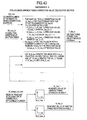
- This detection section detects the correction-applicable cylinders and the correction directions. The details are shown in Fig. 40 .
- Condition 1 is not satisfied, and A1 ⁇ M_omega_K3 ⁇ A2, and V_omega_K3 ⁇ B1.
- Cyl_hos Cyl_K3
- Cyl_hos Cyl_K2
- Dir_hos_F -1
- Dir_hos_A 0
- Dir_hos_S -1
- M_omega_cyl_hos M_omega_K2
- V_ omega_cyl_hos V_omega_K2.
- This calculation section calculates the fuel injection amount correction value (F_hos_n) for each cylinder.
- the details are shown in Fig. 41 : the fuel injection amount correction value (F_hos_n) for the cylinder with the cylinder number of Cyl_hos is calculated as follows.
- This calculation section calculates the intake air amount correction value (Tp_hos_n) for each cylinder.
- the details are shown in Fig. 42 : the intake air amount correction value (Tp_hos_n) for the cylinder with the cylinder number of Cyl_hos is calculated as follows.
- the renewed value (Tp_hos_1) of increased intake air amount is obtained from M_omega_Cyl_hos by referring to the table value (Tbl_Fp_hos_1).
- the renewed value (Tp_hos_0) of decreased intake air amount is obtained from V_omega_Cyl_hos by referring to the table value (Tbl_F_hos_0).
- the values obtained by referring to the table are determined depending on how much intake air amount should be corrected per one renewal with respect to the magnitude (decreased or increased amount) of a mean value of the angular acceleration.
- the table values (Tbl IVO hos n) and (Tbl_IVC_hos_n) are determined depending on what degrees the timings of opening and closing the fuel injection valve should be corrected to.
- the engine operating conditions such as rotational speed and intake air pressure may be referred to for the determination of those values.
- This calculation section calculates the ignition timing correction values (S_hos_n) for each cylinder.
- the details are shown in Fig. 43 : the ignition timing correction value (S_hos_n) for the cylinder with the cylinder number of Cyl_hos is calculated as follows.
Landscapes
- Engineering & Computer Science (AREA)
- Chemical & Material Sciences (AREA)
- Combustion & Propulsion (AREA)
- Mechanical Engineering (AREA)
- General Engineering & Computer Science (AREA)
- Combined Controls Of Internal Combustion Engines (AREA)
- Electrical Control Of Air Or Fuel Supplied To Internal-Combustion Engine (AREA)
- Electrical Control Of Ignition Timing (AREA)
- Output Control And Ontrol Of Special Type Engine (AREA)
Abstract
Description
- This invention relates to an apparatus for controlling an internal combustion engine, and more particularly to a control apparatus capable of detecting and correcting both the dispersion of the torques and the dispersion of the air/fuel ratios, with respect to the respective cylinders.
- With the growing concern about the global environmental problem, the requirement has been more and more increasing for reduction of the exhaust gas emission, namely the emission of CO2 or the fuel consumption, from an automobile. In order to improve the performance of operation, there have recently come to be disseminated the engines that employ variable control valves for the purpose of controlling not only the amount of fuel but also the amount of intake air, fed into the respective cylinders of the engine. For the same purpose, the pressure of injected fuel tends to be increased with the result that there is an increasing tendency that the amounts of fuel injection into the respective cylinders become uneven. With this type of engine, it is necessary to long secure, in the surroundings where the engine is used, the capability to control both the fuel injection amount and the intake air amount, that is, both the torques and the air/fuel ratios, for the respective cylinders of the engine.
-
JP-A-2004-52620 - In general, the intake air flow sensor is disposed apart from the combustion chamber, and therefore such components as an air intake pipe and a throttle that actually dilute the information on the intake air amount for each cylinder, are located between them. Thus, a certain precision deterioration occurs in detecting the intake air amount for each cylinder by the intake air flow sensor. Since the air/fuel ratio sensor is also disposed usually in the exhaust manifold, the air/fuel ratio sensor is located apart from the combustion chamber. Hence, the information on the air/fuel ratio contained in the signal detected by the air/fuel ratio sensor is diluted especially in the operating range of engine where the rotational speed and the fuel flow rate are both low.
- According to this invention, which has been made to solve the above-mentioned problem, there is provided a unit (i.e. control apparatus) for detecting/correcting the dispersion of the air/fuel ratios and the dispersion of the torques, with respect to the respective cylinders with high precision for a short period of time.
-
Fig. 1 schematically shows an engine control apparatus comprising aunit 161 for calculating a mean value of the angular acceleration with respect to each cylinder; aunit 162 for calculating the dispersion of the angular acceleration with respect to each cylinder; aunit 163 for estimating the torque and the air/fuel ratio, with respect to each cylinder on the basis of the calculated mean and the calculated dispersion; and/or aunit 164 for controlling at least one of the intake air amount, the fuel injection amount and the ignition timing, with respect to each cylinder on the basis of the estimated torque and the estimated air/fuel ratio. - If the fuel injection amount for one of the cylinders becomes smaller than the target fuel injection amount, the torque generated as a result of the fuel combustion in that cylinder decreases. In this case, since the air/fuel ratio for the interested cylinder becomes lean, the generated torque becomes unstable (with increased dispersion). If the intake air amount for one of the cylinders becomes larger than the target intake air amount, the torque generated as a result of the fuel combustion in that cylinder remains almost the same (as the fuel injection amount is invariable), but the air/fuel ratio for the cylinder becomes lean. Accordingly, the generated torque becomes unstable (with increased dispersion).
- On the other hand, if the fuel injection amount for one of the cylinders becomes larger than the target fuel injection amount, the torque generated as a result of fuel combustion in that cylinder increases but the air/fuel ratio becomes rich, so that the torque does not become unstable (with non-increasing dispersion). If the intake air amount for one of the cylinders becomes smaller than the target intake air amount, the air/fuel ratio for that cylinder becomes rich. As a result, the torque generated as a result of fuel combustion in the cylinder increases a little, remains invariable, or becomes almost non-unstable (with non-increasing dispersion).
- Further, if both the fuel injection amount and the intake air amount, for one of the cylinders become smaller than their target values, the torque generated as a result of fuel combustion in that cylinder decreases. Since the air/fuel ratio for that cylinder remains almost invariable, the torque does not become unstable (with non-increasing dispersion). On the other hand, if both of the fuel injection amount and the intake air amount, for one of the cylinders become greater than their target values, the torque generated as a result of fuel combustion in that cylinder increases. Since the air/fuel ratio remains almost invariable, the torque does not become unstable (with non-increasing dispersion).
- There is a correlation between torque and angular acceleration. Accordingly, it becomes possible to detect the torque and the air/fuel ratio, for each cylinder on the basis of the magnitude (or mean) and the instability (or dispersion), of the angular acceleration with respect to the individual cylinder. Further, it becomes possible to decide on whether the torque dispersion from the target value is ascribed to the error in the fuel injection amount or the intake air amount. If the torque dispersion is due to the error in the fuel injection amount, the fuel injection amount with respect to the related cylinder is corrected through control. If the torque dispersion is due to the error in the intake air amount, the intake air amount with respect to the related cylinder is corrected through control. Moreover, since the torque can be controlled by adjusting the ingnition timing, the torque correction control through the control of the ignition timing is performed as needed if, for example, the intake air amounts for the respective cylinders cannot be controlled individually. The details of such controls will be given later. Incidentally, it is preferable that the angular accelerations with respect to the respective cylinders should be obtained, in synchronism with the fuel combustion cycles of the respective cylinders, from the signals derived from such sensors capable of obtaining the information on the engine shaft angular position as the crankshaft angular position sensor and the camshaft angular position sensor.
-
Fig. 2 schematically shows a unit for controlling at least one of the intake air amount, the fuel injection amount and the ignition timing, with respect to each cylinder on the basis of the estimated torque and the estimated air/fuel ratio with respect to each cylinder, in such a manner that the differences among the estimated torques and the estimated air/fuel ratios with respect to the respective cylinders become small. - That is to say, the control of the intake air amount, the fuel injection amount and the ignition timing with respect to each cylinder are so performed, as one of the functions described with
Fig. 1 , as to make the differences among the torques and the differences among the air/fuel ratios, with respect to the respective cylinders as small as possible. -
Fig. 3 schematically shows an engine control apparatus wherein theunit 163 for estimating the torque and the air/fuel ratio of each cylinder specifies that cylinder of which the mean of angular acceleration is minimum, and judges that the torque of the specified cylinder is smaller than the torques of any other cylinders and that the air/fuel ratio of the specified cylinder is comparable with the air/fuel ratios of all the other cylinders, when a mean value of the angular acceleration of the specified cylinder is not greater than the predetermined value A1 1nd the dispersion of the angular acceleration of the specified cylinder is smaller than the predetermined value B1. - In other words, as described with
Fig. 1 , the torque with respect to the cylinder having the smallest mean of angular acceleration is considered smaller than the torque of any other cylinder. And when the dispersion of the angular acceleration with respect to one of the cylinders is small, the air/fuel ratio with respect to that cylinder is considered comparable with the air/fuel ratios with respect to all other cylinders. In this case, it is judged that both the fuel injection amount and the intake air amount, with respect to the cylinder decreased. -
Fig. 4 schematically shows an engine control apparatus wherein theunit 163 for estimating the torque and the air/fuel ratio of each cylinder specifies the cylinder of which the mean of angular acceleration is minimum, and judges that the torque of the specified cylinder is smaller than the torques of any other cylinders and that the air/fuel ratio of the specified cylinder is lean as compared with the air/fuel ratios of all the other cylinders, when a mean value of the angular acceleration of the specified cylinder is not greater than the predetermined value A1 and the dispersion of the angular acceleration of the specified cylinder is not smaller than thepredetermined value B 1. - That is to say, as described with
Fig. 1 , the torque of the cylinder having the smallest mean of angular acceleration is considered smaller than the torque of any other cylinder. And when the dispersion of the angular acceleration of one of the cylinders is large, the air/fuel ratio of that cylinder is considered lean as compared with the air/fuel ratios of all the other cylinders. In this case, it is judged that the fuel injection amount of the cylinder decreases, and the intake air amount of the cylinder is invariant or increases. -
Fig. 5 schematically shows an engine control apparatus wherein theunit 163 for estimating the torque and the air/fuel ratio of each cylinder specifies the cylinder of which the mean of angular acceleration is maximum, and judges that the torque of the specified cylinder is greater than the torques of any other cylinders and that the air/fuel ratio of the specified cylinder is comparable with or rich as compared with, the air/fuel ratios of all the other cylinders, when a mean value of the angular acceleration of the specified cylinder is not smaller than the predetermined value A2 and the dispersion of the angular acceleration of the specified cylinder is smaller than thepredetermined value B 1. - That is to say, as described with
Fig. 1 , the torque of the cylinder having the greatest mean of angular acceleration is considered greater than the torque of any other cylinder. And when the dispersion of the angular acceleration of one of the cylinders is small, the air/fuel ratio of that cylinder is considered comparable with or rich as compared with, the air/fuel ratios of all the other cylinders. In this case, it is judged that the fuel injection amount of the cylinder increases (with the intake air amount invariable), or the intake air amount of the cylinder decreases (with the fuel injection amount invariable). -
Fig. 6 schematically shows an engine control apparatus wherein theunit 163 for estimating the torque and the air/fuel ratio of each cylinder specifies the cylinder of which the dispersion of angular acceleration is maximum, and judges that the torque of the specified cylinder is comparable with the torques of any other cylinders and that the air/fuel ratio of the specified cylinder is lean as compared with the air/fuel ratios of all the other cylinders, when a mean value of the angular acceleration of the specified cylinder is greater than the predetermined value A1 and smaller than the predetermined value A2 and the dispersion of the angular acceleration of the specified cylinder is not smaller than the predetermined value B1. - As described with
Fig. 1 , if a mean value of the angular acceleration of one of the cylinders is not largely different from the angular acceleration of any other cylinder, the torque of that cylinder is considered nearly equal to the torque of any other cylinder. If the dispersion of the angular acceleration of one of the cylinders is large, the air/fuel ratio of that cylinder is considered lean as compared with the air/fuel ratios of all the other cylinders. In this case, it is judged that the fuel injection amount of the cylinder remains invariable and the intake air amount of the cylinder increases. -
Fig. 7 schematically shows an engine control apparatus wherein the predetermined value A1 is smaller than a mean value of the angular accelerations of all the cylinders during a predetermined period of time. - As described with
Fig. 3 , the predetermined value A1 is chosen as the threshold for angular acceleration that is used to locate a cylinder whose torque is smaller than the torques of all the other cylinders. Therefore, the predetermined value A1 is set smaller than a mean value of the angular accelerations of all the cylinders. -
Fig. 8 schematically shows an engine control apparatus wherein the predetermined value A2 is greater than a mean value of the angular accelerations of all the cylinders during the predetermined period of time. - As described with
Fig. 5 , the predetermined value A2 is chosen as the threshold for angular acceleration that is used to locate a cylinder whose torque is greater than the torques of any other cylinders. Therefore, the predetermined value A2 is set greater than a mean value of the angular accelerations of all the cylinders. -
Fig. 9 schematically shows an engine control apparatus wherein the predetermined value A1 is negative and the predetermined value A2 is positive when the engine is idling. - In other words, while the engine is idling, a mean value of the angular accelerations of all the cylinders nearly vanishes. Accordingly, the value A1 chosen as the threshold for angular acceleration that is used to locate a cylinder whose torque is smaller than the torques of any other cylinders, is set negative whereas the value A2 chosen as the threshold for angular acceleration that is used to locate a cylinder whose torque is greater than the torques of any other cylinders, is set positive.
-
Fig. 10 schematically shows an engine control apparatus wherein the dispersion of the angular acceleration of each cylinder is represented by the standard deviation or the variance, of the acceleration of that particular cylinder. - In other words, the standard deviation or the variance is introduced as the general index of indicating the dispersion.
-
Fig. 11 schematically shows an engine control apparatus wherein the dispersion of the angular acceleration of each of the cylinders is calculated by applying the weighted moving average method to the square of the absolute value of the angular acceleration of that cylinder, or by applying the weighted moving average method to the absolute value of the angular acceleration of that cylinder. - As described with
Fig. 10 , although the variance or the standard deviation is known as the index of indicating the dispersion, they are not suitable for on-board successive calculation. Therefore, the variance is approximately calculated by using the value, which is suitable for on-board successive calculation, obtained through the application of the weighted moving average method to the square of the absolute value of the angular acceleration of each cylinder, or the standard deviation is approximately calculated by using the value, which is suitable for on-board successive calculation, obtained through the application of the weighted moving average method to the absolute value of the angular acceleration of each cylinder. -
Fig. 12 schematically shows an engine control apparatus wherein the intake air amount of the specific cylinder the torque of which is judged smaller than those of any other cylinders and the air/fuel ratio of which is judged comparable with those of all the other cylinders, is corrected and increased until a mean value of the angular acceleration of the specific cylinder becomes greater than the predetermined value A1; and the fuel injection amount of the specific cylinder is also corrected and increased so as to keep the air/fuel ratio of the specific cylinder in accordance with the increased intake air amount. - As described with
Fig. 3 , with respect to the specific cylinder the torque of which is judged smaller than those of any other cylinders and the air/fuel ratio of which is judged comparable with those of all the other cylinders, it is considered that both the fuel injection amount and the intake air amount of the specific cylinder decreased. Accordingly, until a mean value of the angular acceleration of the specific cylinder becomes greater than the predetermined value A1 (that is, until the decrease in the torque of the specific cylinder ceases), the intake air amount of the specific cylinder is corrected and increased; and the fuel injection amount of the specific cylinder is also corrected and increased so as to keep the air/fuel ratio of the specific cylinder in accordance with the increased intake air amount, in order not to render the air/fuel ratio of the specific cylinder lean. -
Fig. 13 schematically shows an engine control apparatus wherein the fuel injection amount of the specific cylinder the torque of which is judged smaller than those of any other cylinders and the air/fuel ratio of which is judged lean as compared with those of all the other cylinders, is corrected and increased until a mean value of the angular acceleration of the specific cylinder becomes greater than the predetermined value A1 and until the dispersion of the angular acceleration of the specific cylinder becomes smaller than the predetermined value B1. - As described with
Fig. 4 , with respect to the specific cylinder the torque of which is judged smaller than those of any other cylinders and the air/fuel ratio of which is judged leaner than those of any other cylinders, it is considered that the fuel injection amount of the specific cylinder decreased and the intake air amount of the specific cylinder remains invariable or increased. Accordingly, the intake air amount of the specific cylinder is corrected and increased until a mean value of the angular acceleration of the specific cylinder becomes greater than the predetermined value A1 (that is, until the decrease in the torque of the specific cylinder ceases) and until the dispersion of the angular acceleration of the specific cylinder becomes smaller than the predetermined value B1 (that is, until the air/fuel ratio of the specific cylinder ceases becoming lean). -
Fig. 14 schematically shows an engine control apparatus wherein the fuel injection amount of the specific cylinder the torque of which is judged greater than those of any other cylinders and the air/fuel ratio of which is judged comparable with or rich as compared with, those of all the other cylinders, is corrected and decreased until a mean value of the angular acceleration of the specific cylinder becomes smaller than the predetermined value A2. - As described with
Fig. 5 , with respect to the specific cylinder the torque of which is judged greater than those of any other cylinders and the air/fuel ratio of which is judged comparable with or rich as compared with, those of all the other cylinders, it is considered that the fuel injection amount of the specific cylinder increased (with the intake air amount invariable) or the intake air amount of the specific cylinder decreased (with the fuel injection amount invariable). Accordingly, the fuel injection amount of the specific cylinder is corrected and decreased until a mean value of the angular acceleration of the specific cylinder becomes smaller than the predetermined value A2 (that is, until the increase in the torque of the specific cylinder ceases). -
Fig. 15 schematically shows an engine control apparatus wherein the intake air amount of the specific cylinder the torque of which is judged comparable with those of all the other cylinders and the air/fuel ratio of which is judged leaner than those of any other cylinders, is corrected and decreased until the dispersion of the angular acceleration of the specific cylinder becomes smaller than the predetermined value B1. - As described with
Fig. 6 , with respect to the specific cylinder the torque of which is judged comparable with those of all the other cylinders and the air/fuel ratio of which is judged leaner than those of any other cylinders, it is considered that the fuel injection amount of the specific cylinder is invariable and the intake air amount of the specific cylinder increased. Accordingly, the intake air amount of the specific cylinder is corrected and decreased until the dispersion of the angular acceleration of the specific cylinder becomes smaller than the predetermined value B1 (that is, until the air/fuel ratio of the specific cylinder ceases becoming lean). -
Fig. 16 schematically shows an engine control apparatus wherein the ignition timing of the specific cylinder the torque of which is judged smaller than those of any other cylinders and the air/fuel ratio of which is judged comparable with those of all the other cylinders, is corrected and advanced in angle until a mean value of the angular acceleration of the specific cylinder becomes greater than the predetermined value A1. - As described with
Fig. 3 , with respect to the specific cylinder the torque of which is judged smaller than those of any other cylinders and the air/fuel ratio of which is judged comparable with those of all the other cylinders, it is considered that both the fuel injection amount and the intake air amount, of the specific cylinder decreased. In the case where the intake air amounts for the respective cylinders cannot be controlled, if only the fuel injection amount for the specific cylinders is increased, the decrease in the torque of the specific cylinder is indeed prevented, but the air/fuel ratio of the specific cylinder becomes rich. If this happens, the decrease in the torque can be prevented by correcting and advancing in angle the ignition timing of the specific cylinder. -
Fig. 17 schematically shows an engine control apparatus wherein the ignition timing of the specific cylinder the torque of which is judged greater than those of any other cylinders and the air/fuel ratio of which is judged comparable with or rich as compared with, those of all the other cylinders, is corrected and retarded in angle until a mean value of the angular acceleration of the specific cylinder becomes smaller than the predetermined value A2. - As described with
Fig. 5 , with respect to the specific cylinder the torque of which is judged greater than those of any other cylinders and the air/fuel ratio of which is judged comparable with or rich as compared with, those of all the other cylinders, it is considered that the fuel injection amount of the specific cylinder increased (with the intake air amount invariable) or the intake air amount of the specific cylinder decreased (with the fuel injection amount invariable). The torque can also be decreased by correcting and retarding in angle the ignition timing of the specific cylinder. -
Fig. 18 schematically shows an engine control apparatus wherein the specific cylinder with respect to which a mean value of the angular acceleration is minimum, is preferentially located; and when a mean value of the angular acceleration of the specific cylinder is not greater than the predetermined value A1 and when the dispersion of the angular acceleration of the specific cylinder is not smaller than the predetermined value B1, the fuel injection amount of the specific cylinder is preferentially corrected and increased until the mean becomes greater than A1 and until the dispersion becomes smaller than B1. - As described with
Fig. 1 , the torque of the cylinder of which a mean value of the angular acceleration is minimum, is judged smaller than those of any other cylinders. Also, if the dispersion of the angular acceleration of the specific cylinder is great, the air/fuel ratio of the specific cylinder is judged lean as compared with those of all the other cylinders. The cylinder the torque of which is smaller than those of any other cylinders and the air/fuel ratio of which is judged lean as compared with those of all the other cylinders, is the most unstable cylinder. Accordingly, the most unstable cylinder is preferentially located and the fuel injection amount of the most unstable cylinder is preferentially corrected and increased. -
Fig. 19 schematically shows an engine control apparatus wherein the mean value of the fuel injection amount correction values for all the cylinders is calculated, and the final fuel injection amount correction value for one of the cylinders is obtained by subtracting the mean from the fuel injection amount correction value for that cylinder. - That is to say, according to the fuel injection amount correction procedures described with the engine control apparatuses shown in
Figs. 12 ~ 14 , and18 , the fuel injection amount for one of the cylinders is corrected, and increased or decreased at a time, and this process is successively repeated for all the cylinders. In such a successive correction procedure, there is a possibility that the DC component of the fuel injection amount correction value (i.e. mean of the fuel injection amount correction values for all the cylinders) is drifted. In order to correct the drift component, the mean of the fuel injection amounts for all the cylinders is calculated, and the final fuel injection amount correction value for one of the cylinders is obtained by subtracting the mean from the fuel injection amount correction value for that cylinder. -
Fig. 20 schematically shows an engine control apparatus wherein the mean value of the intake air amount correction values for all the cylinders is calculated, and the final intake air amount correction value for one of the cylinders is obtained by subtracting the mean from the intake air amount correction value for that cylinder. - That is to say, according to the intake air amount correction procedures described with
Figs. 12 and15 , the intake air amount for one of the cylinders is corrected, and increased or decreased, and this process is successively repeated for all the cylinder. As described withFig. 20 , in order to correct the drift component, the mean of the intake air amount correction values for all the cylinders is calculated, and the final intake air amount correction value for one of the cylinders is obtained by subtracting the mean from the intake air amount correction value for that cylinder. -
Fig. 21 schematically shows an engine control apparatus wherein the mean value of the ignition timing correction values for all the cylinders is calculated, and the final ignition timing correction value for one of the cylinders is obtained by subtracting the mean from the ignition timing correction value for that cylinder. - That is to say, according to the ignition timing correction procedures described with
Figs. 16 and17 , the ignition timing for one of the cylinders is corrected, and advanced or retarded in angle, and this process is successively repeated for all the cylinders. As described withFig. 20 , in order to correct the drift component, the mean of the ignition timing correction values for all the cylinders is calculated, and the final ignition timing correction value for one of the cylinders is obtained by subtracting the mean from the ignition timing correction value for that cylinder. - According to the present procedure of control, a single stage of correction does not necessarily complete the correction of errors in the fuel injection amount and the intake air amount. For example, if both the fuel injection amount and the intake air amount are deviated from the target value in such a manner that they tend to increase, the fuel injection amount is first corrected and decreased in accordance with the procedure described with
Fig. 14 until the increase in torque is canceled. Since the intake air amount is not corrected and decreased in this case, the air/fuel ratio becomes lean. Then, the intake air amount is corrected and decreased in accordance with the procedure described withFig. 15 so that the fuel injection amount and the intake air amount are properly corrected through this two stage correction procedure. The same effect can be obtained in some other cases. However, since this type of control is rather often employed, the cylinder for which either the fuel injection amount or the intake air amount is erroneous can be located quickly (i.e. located before both of them become erroneous). There are four cases where error occurs in the fuel injection amount or the intake air amount: (1) superfluous fuel amount, (2) meager fuel amount, (3) superfluous intake air amount, and (4) meager intake air amount. Of those four cases, the three cases ((1) superfluous fuel amount, (2) meager fuel amount, (3) superfluous intake air amount) can be corrected for each cylinder through a single stage correction procedure. Even in the case of (3) superfluous intake air amount or in the case where errors occur in both the fuel injection amount and the intake air amount, the errors can be corrected through a two-stage location/correction procedure. - As described above, the dispersions of the air/fuel ratios and the torques, with respect to the respective cylinders can be detected and corrected with high precision and for a short period of time.
- According to this invention, since the intake air amount, the fuel injection amount and the ignition timing of each cylinder are properly corrected in such a manner that the differences among the torques and the air/fuel ratios of the respective cylinders become small, the performance of the engine whose structure is ever becoming complicated can be long secured in practical environments, and therefore exhaust gas, CO2 and fuel cost can be prevented from increasing.
- The other embodiments of the present invention are disclosed as follows.
- The engine control apparatus, wherein the ignition timing of the specific cylinder the torque of which is judged smaller than those of any other cylinders and the air/fuel ratio of which is judged comparable with those of all the other cylinders, is corrected and advanced in angle until a mean value of the angular acceleration of the specific cylinder becomes greater than the predetermined value A1.
- The engine control apparatus, wherein the ignition timing of the specific cylinder the torque of which is judged greater than those of any other cylinders and the air/fuel ratio of which is judged comparable with or rich as compared with, those of all the other cylinders, is corrected and retarded in angle until a mean value of the angular acceleration of the specific cylinder becomes smaller than the predetermined value A2.
- The engine control apparatus, wherein the specific cylinder with respect to which a mean value of the angular acceleration is minimum, is preferentially located; and when a mean value of the angular acceleration of the specific cylinder is not greater than the predetermined value A1 and when the dispersion of the angular acceleration of the specific cylinder is not smaller than the predetermined value B1, the fuel injection amount of the specific cylinder is preferentially corrected and increased until the mean becomes greater than A1 and until the dispersion becomes smaller than
B 1. - The engine control apparatus, wherein the mean of the fuel injection amount correction values for all the cylinders is calculated, and the final fuel injection amount correction value for one of the cylinders is obtained by subtracting the mean from the fuel injection amount correction value for that cylinder.
- The engine control apparatus, wherein the mean of the intake air amount correction values for all the cylinders is calculated, and the final intake air amount correction value for one of the cylinders is obtained by subtracting the mean from the intake air amount correction value for that cylinder.
- The engine control apparatus, wherein the mean of the ignition timing correction values for all the cylinders is calculated, and the final ignition timing correction value for one of the cylinders is obtained by subtracting the mean from the ignition timing correction value for that cylinder.
-
-
Fig. 1 shows in block diagram an engine control apparatus according to this invention; -
Fig. 2 shows in block diagram another engine control apparatus according to this invention; -
Fig. 3 shows in block diagram another engine control apparatus according to this invention; -
Fig. 4 shows in block diagram another engine control apparatus according to this invention; -
Fig. 5 shows in block diagram another engine control apparatus according to this invention; -
Fig. 6 shows in block diagram another engine control apparatus according to this invention; -
Fig. 7 shows in block diagram another engine control apparatus according to this invention; -
Fig. 8 shows in block diagram another engine control apparatus according to this invention; -
Fig. 9 shows in block diagram another engine control apparatus according to this invention; -
Fig. 10 shows in block diagram another engine control apparatus according to this invention; -
Fig. 11 shows in block diagram another engine control apparatus according to this invention; -
Fig. 12 shows in block diagram another engine control apparatus according to this invention; -
Fig. 13 shows in block diagram another engine control apparatus according to this invention; -
Fig. 14 shows in block diagram another engine control apparatus according to this invention; -
Fig. 15 shows in block diagram another engine control apparatus according to this invention; -
Fig. 16 shows in block diagram another engine control apparatus according to this invention; -
Fig. 17 shows in block diagram another engine control apparatus according to this invention; -
Fig. 18 shows in block diagram another engine control apparatus according to this invention; -
Fig. 19 shows in block diagram another engine control apparatus according to this invention; -
Fig. 20 shows in block diagram another engine control apparatus according to this invention; -
Fig. 21 shows in block diagram another engine control apparatus according to this invention; -
Fig. 22 schematically shows an engine control system used in the first through third embodiments of this invention; -
Fig. 23 shows in block diagram the internal structure of a control unit used in the first through third embodiments of this invention; -
Fig. 24 shows in block diagram the entire control system used in the first and second embodiments of this invention; -
Fig. 25 shows in block diagram the basic fuel injection amount calculation section used in the first through third embodiments of this invention; -
Fig. 26 shows in block diagram the control permission flag calculation section used in the first embodiment of this invention; -
Fig. 27 shows in block diagram the per-cylinder angular acceleration characteristic calculation section used in the first embodiment of this invention; -
Fig. 28 shows in block diagram the correction-applicable cylinder and correction direction detection section used in the first and second embodiments of this invention; -
Fig. 29 shows in block diagram the section for calculating the information on the cylinder a mean value of the angular acceleration of which is minimum/maximum and the information on the cylinder the dispersion of the angular acceleration of which is maximum, the section being used in the first embodiment of this invention; -
Fig. 30 shows in block diagram the correction-applicable cylinder and correctiondirection detection section 2 used in the first and second embodiments of this invention; -
Fig. 31 shows in block diagram the per-cylinder fuel injection amount correction value calculation section used in the first embodiment of this invention; -
Fig. 32 shows in block diagram the per-cylinder intake air amount correction value calculation section used in the first embodiment of this invention; -
Fig. 33 shows in block diagram the control permission flag calculation section used in the second and third embodiments of this invention; -
Fig. 34 shows in block diagram the per-cylinder angular acceleration characteristic calculation section used in the second and third embodiments of this invention; -
Fig. 35 shows in block diagram the section for calculating the information on the cylinder a mean value of the angular acceleration of which is minimum/maximum and the information on the cylinder the dispersion of the angular acceleration of which is maximum, the section being used in the second and third embodiments of this invention; -
Fig. 36 shows in block diagram the per-cylinder fuel injection amount correction value calculation section used in the second embodiment of this invention; -
Fig. 37 shows in block diagram the per-cylinder intake air amount correction value calculation section used in the second embodiment of this invention; -
Fig. 38 shows in block diagram the entire control system used in the third embodiment of this invention; -
Fig. 39 shows in block diagram the correction-applicable cylinder and correction direction detection section used in the third embodiment of this invention; -
Fig. 40 shows in block diagram the correction-applicable cylinder and correction direction detection section used in the third embodiment of this invention; -
Fig. 41 shows in block diagram the per-cylinder fuel injection amount correction value calculation section used in the third embodiment of this invention; -
Fig. 42 shows in block diagram the per-cylinder intake air amount correction value calculation section used in the third embodiment of this invention; and -
Fig. 43 shows in block diagram the per-cylinder ignition timing correction value calculation section used in the third embodiment of this invention. -
Fig. 22 schematically shows a system for controlling an engine according to an embodiment of this invention. In a multiple-cylinder engine 9 (e.g. four-cylinder engine in this embodiment), ambient air flows into a cylinder through anair cleaner 1 via anintake manifold 4 and acollector 5. The flow rate of the intake air is detected by an air-flow sensor 2 and then adjusted by anelectronic throttle 3. The temperature of the intake air is detected by an intake-air temperature sensor 29. Acrank angle sensor 15 outputs a signal generated every 10 degrees of the rotation of the crankshaft and a signal generated every combustion cycle. Awater temperature sensor 14 detects the temperature of the engine coolant. Anaccelerator depression sensor 13 detects the degree of the actuation of theaccelerator 6 so as to detect the torque demanded by the driver. - The signals outputted from the
accelerator depression sensor 13, the air-flow sensor 2, the intake-air temperature sensor 29, athrottle aperture sensor 17 attached to theelectronic throttle 3, thecrank angle sensor 15, and thewater temperature sensor 14, are delivered to acontrol unit 16 which, described in detail later, determines the operating condition of theengine 9 on the basis of those signals and calculates the optimal values of the main manipulated variables for engine operation such as intake-air amount, fuel injection amount and ignition timing. - The target intake air amount calculated by the
control unit 16 is converted to a signal for determining the target throttle aperture and further to a signal which is sent to theelectronic throttle 3 to drive the same. The fuel injection amount is converted to a valve-opening signal, which is sent to afuel injector 7. To theignition plug 8 is applied a signal for firing theplug 8 in synchronism with the timing calculated by thecontrol unit 16. - The injected fuel is mixed with the air flowing into the cylinder of the
engine 9 through the intake manifold so that air-fuel mixture is formed in thecylinder 9. The air-fuel mixture is explosively combusted by being ignited with sparks generated by thespark plug 8 in accordance with a predetermined timing, and the pressure of explosion pushes the piston to generate the motive force of the engine. After the explosion, exhaust gas is sent to a 3-way catalyst 11 via anexhaust manifold 10. Part of the exhaust gas is returned to theintake manifold 4 through an exhaustgas recirculation pipe 18. The amount of the recirculated exhaust gas is controlled by an exhaust gas recirculation (EGR)control valve 19. - A catalyst-upstream A/
F sensor 12 is disposed between theengine 9 and the 3-way catalyst 11 whereas a catalyst-downstream O2 sensor 20 is disposed downstream of the 3-way catalyst 11. -
Fig. 23 shows in block diagram the internal structure of thecontrol unit 16. The control unit (ECU) 16 receives the outputs of the air-flow sensor 2, the catalyst- upstream A/F sensor 12, theaccelerator depression sensor 13, thewater temperature sensor 14, acrank angle sensor 15, thethrottle aperture sensor 17, the catalyst-downstream O2 sensor 20, the intake-air temperature sensor 29, and avehicle speed sensor 31. These signals are initially processed by aninput circuit 24 so as to remove noise, and then sent to an input/output port 25. The values received by the input/output port 25 are stored in aRAM 23 and subjected to calculation inCPU 21. The control program which executes the algorithm of the calculation is previously written in aROM 22. The values that have been calculated according to the control program and that represent the actuating signals for actuating the respective control elements (or actuators), are stored in theRAM 23 and then sent to the input/output port 25. The actuating signal for the ignition plug is an ON/OFF signal which appears when the primary coil of the ignition output circuit draws current, and disappears when the current through the primary coil is interrupted. The instant at which ignition takes place occurs in response to the transition of the actuating signal from ON-state to OFF-state. The signal for firing the ignition plug, which has been set in the output port, is amplified by an ignitionsignal output circuit 26 to such an extent that it has energy enough to fire the plug, before it is supplied to the plug. The actuation signal for the fuel injector is also an ON/OFF signal that appears when fuel is to be injected and disappears when fuel is not to be injected. This signal is sent to thefuel injector 7 after it has been amplified by a fuelinjector drive circuit 27 to such an extent that it has energy enough to actuate thefuel injector 7. The actuating signal for setting the target aperture of theelectronic throttle 3 is sent to theelectronic throttle 3 via an electronicthrottle drive circuit 28. The actuating signal for setting the target lift of avariable intake valve 30 and the target instant for opening or closing thevalve 30, is sent to thevariable intake valve 30 via a variable intakevalve drive circuit 32. - Now, the control program to be written into the
ROM 22 will be described.Fig. 24 shows in block diagram the entire control system, which comprises: - * Basic fuel injection amount Calculation Section (
Fig. 25 ) - * Control Permission Flag Calculation Section (
Fig. 26 ) - * Per-cylinder Angular Acceleration Characteristic Calculation Section (
Fig. 27 ) - * Correction-Applicable Cylinder and Correction Direction Detection Section (
Fig. 28 ) - * Per-cylinder Fuel Injection Amount Correction Value Calculation Section (
Fig. 31 ) - * Per-cylinder Intake Air Amount Correction Value Calculation Section (
Fig. 32 ) - The "basic fuel injection amount calculation section" calculates the basic fuel injection amount (Tp0). The "control permission flag calculation section" calculates the flag (fp_seigyo) for permitting the execution of the correction of fuel injection amount and intake air amount for each cylinder. The "per-cylinder angular acceleration characteristic calculation section" calculates the mean (M_omega_n (n: cylinder number)) of the angular acceleration of each cylinder and the variance (V_omega_n (n: cylinder number)) of the angular acceleration of each cylinder, representative of the angular acceleration characteristics of each cylinder, when the control permmission is issued. The "correction-applicable cylinder and correction direction detection section" calculates, on the basis of the above mentioned angular acceleration characteristics, the cylinder numbers (Cyl_hos) of the correction-applicable cylinders; the correction direction (Dir_hos_F) of whether the fuel injection amount for each correction-applicable cylinder is to be increased or decreased; the correction direction (Dir_hos_A) of whether the intake air amount for each correction-applicable cylinder is to be increased or decreased; the mean (M_omega_Cyl_hos) of the angular acceleration with respect to the correction-applicable cylinder; and the variace (V_omega_Cyl_hos) of the angular acceleration with respect to the correction-applicable cylinder. The "per-cylinder fuel injection amount correction value calculation section" calculates the fuel injection amount correction value (F_hos_n (n: cylinder number)) for each cylinder on the basis of the various parameters calculated by the correction-applicable cylinder and correction direction detection section. The "per-cylinder intake air amount correction value calculation section" calculates the intake air amount correction value (IVO_hos_n, IVC_hos_n) for each cylinder on the basis of the various parameters calculated by the correction-applicable cylinder and correction direction detection section. Here, (IVO_hos_n) is the correction value applied to the opening instant (IVO_n) of the fuel injector of the number "n" cylinder, and (IVC_hos_n) is the correction value applied to the closing instant (IVC_n) of the fuel injector of the number "n" cylinder. Various methods of calculating IVO_n and IVC_n have been already proposed to date, and since those methods are not directly related to this invention, the detailed description thereof is omitted here. The respective calculation sections mentioned above will be described in detail below.
- This calculation section calculates the basic fuel injection amount (Tp0). To be concrete, it is calculated by using the expression shown in
Fig. 25 . In that expression, Cyl denotes the number of cylinders, and K0 is determined on the basis of the specification (i.e. relationship between fuel injection pulse width and fuel injection amount) of the injectors associated with the cylinders. - This calculation section calculates the control permission flag (fp_seigyo). The flow of calculation is as shown in
Fig. 26 . The execution of control is permitted if the difference (ΔApo) between the present and previous values of accelerator depression remains within a predetermined range for a predetermined period of time, if the difference (ΔTp0) between the present and previous values of the basic fuel injection amount remains within a predetermined range for a predetermined period of time, and if the difference (ΔNe) between the present and previous values of engine rotational speed remains within a predetermined range for a predetermined period of time. - This calculation section calculates the mean (M_omega_n (n: cylinder number)) of the angular acceleration of one of the cylinders representative of the angular acceleration characteristic of that cylinder, and the variance (V_omega_n (n: cylinder number)) of the angular acceleration of one of the cylinders. The flow of calculation is as shown in
Fig. 27 . The angular acceleration (omega_n) of the n-th cylinder is obtained from the engine rotational speed (Ne). In more concrete terms, the mean of Ne's is calculated every combustion cycle; the difference between the mean and previous value of Ne is termed (omega_n); and the mean (M_omega_n) of the angular acceleration of the n-th cylinder over a predetermined number of cycles is derived from (omega_n). The variance (V_omega_n) of the angular acceleration of the n-th cylinder over a predetermined number of cycles is also derived from (omega_n). - This calculation section consists of a "section for calculating both the information on the cylinder of which the mean of angular acceleration is minimum/maximum and the information on the cylinder of which the variance of angular acceleration is maximum "and a "correction-applicable cylinder and correction
direction detection section 2". The details of the respective calculation sections will be described in the following.
[Section for Calculating both the Information on the Cylinder of Which the Mean of Angular Acceleration is Minimum/Maximum and the Information on the Cylinder of Which the Variance of Angular Acceleration is Maximum (Fig. 29 )] - This calculation section calculates both the information on the cylinder of which the mean of angular acceleration is minimum/maximum and the information on the cylinder of which the variance of angular acceleration is maximum. The details are shown in
Fig. 29 : - *The mimimum value (M_omega_K1) of M_omega_n is obtained. Let Cyl_K1 denote the cylinder number of the cylinder having the minimum M_omega_n, and let V_omega_K1 denote the V_omega_n of the cylinder having the cylinder number Cyl_K1.
- *The maximim value (M_omega_K2) of M_omega_n is obtained. Let Cyl_K2 denote the cylinder number of the cylinder having the maximim M_omega_n, and let V_omega_K2 denote the V_omega_n of the cylinder having the cylinder number Cyl_K2.
- * The maximim value (V_omega_K3) of V_omega_n is obtained. Let Cyl_K3 denote the cylinder number of the cylinder having the maximim V_omega_n, and let M_omega_K3 denote the M_omega_n of the cylinder having the cylinder number Cyl_K3.
- *Let A1 denote the value equal to the mean of M_omega_n minus K1, and let A2 denote the value equal to the mean of M_omega_n plus K2.
- This detection section detects the correction-applicable cylinders and the correction directions. The details are shown in
Fig. 30 . - M_omega_K1 ≦ A1, and V_omega_ K1 ≧ B1.
-
Condition 1 is not satisfied, and A1 < M_omega_K3 < A2, and V_omega_K3 ≧ B1. - Neither of
Conditions - None of
Conditions - If
Condition 1 is satisfied, then Cyl_hos = Cyl_K1, Dir_hos_F = 1, Dir_hos_A= 0, M_omega_cyl_hos = M_omega_K1, and V_ omega_cyl_hos = V_omega_K1. - If
Condition 2 is satisfied, then Cyl_hos = Cyl_K1, Dir_hos_F = 0, Dir_hos_A = -1, M_omega_cyl_hos = M_omega_K3, and V_ omega_cyl_hos = V_omega_K3. - If
Condition 3 is satisfied, then Cyl_hos = Cyl_K3, Dir_hos_F = 1, Dir_hos_A= 1, M_omega_cyl_hos = M_omega_K1, and V_ omega_cyl_hos = V_omega_K1. - If
Condition 4 is satisfied, then Cyl_hos = Cyl_K2, Dir_hos_F = -1, Dir_hos_A = 0, M_omega_cyl_hos = M_omega_K2, and V_ omega_cyl_hos = V_omega_K2. - When the correction direction flags (Dir_hos_F, Dir_hos_A) take the value of "1", correction is in the direction of increase. When they take the value of "-1", correction is in the direction of decrease. When they take the value of "0", no correction takes place.
- This calculation section calculates the fuel injection amount correction value (F_hos_n) for each cylinder. The details are shown in
Fig. 31 : the fuel injection amount correction value (F_hos_n) for the cylinder with the cylinder number of Cyl_hos is calculated as follows. - * F hos n = F_hos_n (previous value) + F_hos_1 when Dir_hos_F = 1 and Dir_hos_ A=0.
- * F_hos_n = KXTp_hos_n (n = Cyl_hos) when Dir_hos_F = 1 and Dir_hos_A = 1.
- * F_hos_n = F_hos_n (previous value) - F_hos_0 when Dir_hos_F = -1.
- * F_hos_n = F_hos_n (previous value) when Dir_hos_F = 0.
- *The fuel injection amount correction value (F_hos_n) for the cylinder with a cylinder number other than Cyl_hos remains equal to the provious value, i.e. F_hos_n = F_hos_n (previous value).
- Further, the renewed value (F_hos_1) of increased fuel injection amount is obtained from M_omega_Cyl_hos by referring to the table value (Tbl_F_hos_1). The renewed value (F_hos_0) of decreased fuel injection amount is obtained from M_omega_Cyl_hos by referring to the table value (Tb1_F_hos_0). The values obtained by referring to the table are determined depending on how much fuel injection amount should be corrected per one renewal with respect to the magnitude (decreased or increased amount) of a mean value of the angular acceleration.
- This calculation section calculates the intake air amount correction value (Tp_hos_n) for each cylinder. The details are shown in
Fig. 32 : the intake air amount correction value (Tp_hos_n) for the cylinder with the cylinder number of Cyl_hos is calculated as follows. - * Tp_hos_n = Tp_hos_n (previous value) + Tp_hos_1 when Dir_hos_A = 1.
- * Tp_hos_n = Tp_hos_n (previous value) - Tp_hos_0 whenDir_hos_A= -1.
- * Tp_hos_n = Tp_hos_n (previous value) when Dir_hos_A = 0.
- *The intake air amount correction value (Tp_hos_n) for the cylinder with a cylinder number other than Cyl_hos remains equal to the provious value, i.e. Tp_hos_n = Tp_hos_n (previous value).
- *The intake air valve opening time correction value (IVO_hos_n) for each cylinder is calculated from Tp_hos_n by referring to the table value (Tb1_IVO_hos_n).
- * The intake air valve closing time correction value (IVC_hos_n) for each cylinder is calculated from Tp_hos_n by referring to the table value (Tb1_IVC_hos_n).
- Further, the renewed value (Tp hos-1) of increased intake air amount is obtained from M_omega_Cyl_hos by referring to the table value (Tb1_Tp_hos_1). The renewed value (Tp_hos_0) of decreased intake air amount is obtained from V_omega_Cyl_hos by referring to the table value (Tb1_Tp_hos_0). The values obtained by referring to the table are determined depending on how much intake air amount should be corrected per one renewal with respect to the magnitude (decreased or increased amount) of a mean value of the angular accelerations. The table values (Tb1_Tp_hos_1) and (Tb1_Tp_hos_0) are determined depending on how much opening and closing times of the intake air valve should be corrected with respect to the intake air amount correction value. The engine operating conditions such as rotational speed and intake air amount may be referred to for the determination of those values.
- In the second embodiment of this invention, the control of interest is performed during engine idling. As described with
Fig. 11 , the dispersion of the angular acceleration for each cylinder is obtained by processing the square of the absolute value of the acceleration with the weighted moving average method. Moreover, as shown withFigs. 19 and20 , the drift compomnents of the fuel injection amount correction value and the intake air amount correction value, for each cylinder are subjected to correction. -
Fig. 22 schematically shows an engine control system according to another embodiment of this invention. Since this system is similar to the system described above as the first embodiment of this invention, the detailed description thereof is omitted.Fig. 23 schematically shows the internal structure of acontrol unit 16. Since thecontrol unit 16 is the same as that described above in the first embodiment, its detailed description is omitted.Fig. 24 shows in block diagram an engine control system as a whole, which is the same as that described above in the first embodiment, and its detailed description is omitted. The details of the respective calculation sections will be described as follows. - This calculation section calculates the basic fuel injection amount (Tp0). The procedure of the calculation is specifically shown in
Fig. 18 . However, since the procedure is the same as that described above in the first embodiment, the detail thereof is omitted. - This calculation section calculates the control permission flag (fp_seigyo). The procedure of the calculation is specifically shown in
Fig. 33 . The execution of control is permitted (i.e. fp_seigyo = 1) if the difference (ΔApo) between the present and previous values of accelerator depression remains within a predetermined range for a predetermined period of time, if the difference (ΔTp0) between the present and previous values of the basic fuel injection amount remains within a predetermined range for a predetermined period of time, if the difference (ΔNe) between the present and previous values of engine rotational speed remains within a predetermined range for a predetermined period of time, and if the engine is idling. - This calculation section calculates the mean (M_omega_n (n: cylinder number)) and the variance (V_omega_n (n: cylinder number)) of the angular acceleration for each cylinder, representing the angular acceleration characteristic for each cylinder. The flow of calculation is as shown in
Fig. 34 . The angular acceleration (omega_n) of the n-th cylinder is obtained from the engine rotational speed (Ne). In more concrete terms, the mean of Ne is calculated every combustion cycle; the difference between the means for the current and previous cycles is termed omega_n; and the mean (M_omega_n) of the angular acceleration of the n-th cylinder is approximately obtained by applying the moving average procedure to (omega_n). Further, the variance (V_omega_n) of the angular acceleration of the n-th cylinder is obtained by processing the square of the absolute value of (omega_n) with the moving average procedure. - This calculation section consists of a "section for calculating both the information on the cylinder of which a mean value of the angular acceleration is minimum/maximum and the information on the cylinder of which the variance of the angular acceleration is maximum" and a " correction-applicable cylinder and correction
direction detection section 2". These calculation sections are the same in structure as those described above in the first embodiment. The details of the respective calculation sections will be described in the following. - This calculation section calculates both the information on the cylinder of which a mean value of the angular acceleration is minimum/maximum and the information on the cylinder of which the variance of the angular acceleration is maximum. The details are shown in
Fig. 35 : - *The mimimum value (M_omega_K1) of M_omega_n is obtained. Let Cyl_K1 denote the cylinder number of the cylinder having the minimum M_omega_n, and let V_omega_K1 denote the V_omega_n of the cylinder having the cylinder number Cyl_K1.
- * The maximim value (M_omega_K2) of M_omega_n is obtained. Let Cyl_K2 denote the cylinder number of the cylinder having the maximim M_omega_n, and let V_omega_K2 denote the V_omega_n of the cylinder having the cylinder number Cyl_K2.
- * The maximim value (V_omega_K3) of V_omega_n is obtained. Let Cyl_K3 denote the cylinder number of the cylinder having the maximim V_omega_n, and let M_omega_K3 denote the M_omega_n of the cylinder having the cylinder number Cyl_K3.
- *Let A1 be equal to -1, and let A2 be equal to K2. That is, let the mean of M_omega_n be 0.
- This detection section detects the corrction-applicable cylinder and the correction direction. The procedure of the detection is as shown in
Fig. 30 . The detection section is the same in structure as that described above in the first embodiment, and therefore the detail thereof is omitted. - This calculation section calculates the fuel injection amount correction value (F_hos_n) for each cylinder. The details are shown in
Fig. 36 : the fuel injection amount correction value (F_hos_n) for the cylinder with the cylinder number of Cyl_hos is calculated as follows. - * F_hos_a_n = F_hos_n (previous value) + F_hos_1 when Dir_hos_F = 1 and Dir-hos-A = 0.
- * F_hos_a_n = KXTp_hos_n (n = Cyl_hos) when Dir_hos_F = 1 and Dir_hos_A =1.
- * F_hos_a_n = F_hos_n (previous value) - F_hos_0 when Dir_hos_F = -1.
- * F_hos_a_n = F_hos_n (previous value) when Dir_hos_F = 0.
- * (F_hos_a_n) for the cylinder with a cylinder number other than Cyl_hos remains equal to the provious value, i.e. F_hos_a_n = F_hos_n (previous value).
- *Let M_F_hos denote the mean of F_hos_n (previous values) for all the cylunders, and let F_hos_n denote the value equal to F_hos_a_n minus M_F_hos. This process is equivalent to the corrrection of drift compoment.
- The renewed value (F_hos_1) of increased fuel injection amount is obtained from M_omega_Cyl_hos by referring to the table value (Tbl_F_hos_1). The renewed value (F_hos_0) of decreased fuel injection amount is obtained from M_omega_Cyl_hos by referring to the table value (Tbl_F_hos_0). The values obtained by referring to the table are determined depending on how much fuel injection amount should be corrected per one renewal with respect to the magnitude (decreased or increased amount) of a mean value of the angular acceleration.
- This calculation section calculates the intake air amount correction value (Tp_hos_n) for each cylinder. The details are shown in
Fig. 37 : the intake air amount correction value (Tp_hos_n) for the cylinder with the cylinder number of Cyl_hos is calculated as follows. - * Tp_hos_a_n = Tp_hos_n (previous value) + Tp_hos_1 when Dir_hos_A = 1.
- * Tp_hos_a_n = Tp_hos_n (previous value) - Tp_hos_0 when Dir_hos_A = -1.
- * Tp_hos_a_n = Tp_hos_n (previous value) when Dir_hos_A = 0.
- * (Tp_hos_n) for the cylinder with a cylinder number other than Cyl_hos remains equal to the provious value, i.e. Tp_hos_a_n = Tp_hos_n (previous value).
- *The intake air valve opening time correction value (IVO_hos_n) for each cylinder is calculated from Tp_hos_n by referring to the table value (Tbl_IVO_hos_n).
- * The intake air valve closing time correction value (IVC_hos_n) for each cylinder is calculated from Tp_hos_n by referring to the table value (Tbl_IVC_hos_n).
- * Let M_Tp_hos denote the mean of Tp_hos_n (previous values) for all the cylunders, and let Tp_hos_n denote the value equal to Tp_hos_a_n minus M_Tp_hos. This process is equivalent to the corrrection of drift compoment.
- Further, the renewed value (Tp_hos_0) of increased intake air amount is obtained from M_omega_Cyl_hos by referring to the table value (Tbl_Fp_hos_0). The renewed value (Tp_hos_0) of decreased intake air amount is obtained from V_omega_Cyl_hos by referring to the table value (Tbl_Tp_hos_0). The values obtained by referring to the table are determined depending on how much intake air amount should be corrected per one renewal with respect to the magnitude (decreased or increased amount) of a mean value of the angular acceleration. Moreover, the table values (Tbl_IVO_hos_n) and (Tbl_IVC_hos_n) are determined depending on what degrees the timings of opening and closing the fuel injection valve should be corrected to. The engine operating conditions such as rotational speed and intake air pressure may be referred to for the determination of those values.
- This embodiment considers the control through the correction of ignition timing as described with
Figs. 16 and17 . -
Fig. 22 schematically shows an engine control system according to the third embodiment of this invention. Since this system is similar to the system described above as the first embodiment of this invention, the detailed description thereof is omitted.Fig. 23 schematically shows the internal structure of acontrol unit 16. Since thecontrol unit 16 is the same as that described above in the first embodiment, its detailed description is omitted.Fig. 38 shows in block diagram an engine control system as a whole, which is the same as that described above in the first or second embodiment, except the addition of a per-cylinder ignition timing correction value calculation section. The ignition timing correction values (S_hos_n) for the respective cylinders are calculated on the basis of the parameters calculated by the correction-applicable cylinder and correction direction detection section. As shown inFig. 38 , S_hos_n is the correction amount added to the reference ignition timing (ADVO). Various procedures for calculating ADVO have hitherto been proposed and since those procedures are not directly related to this inventyion, their details are not explained here. The detailed description of the respective calculation sections will be given below. - This calculation section calculates the basic fuel injection amount (Tp0). The procedure of the calculation is specifically shown in
Fig. 18 . However, since the procedure is the same as that described above in the first embodiment, the detail thereof is not explained. - This calculation section calculates the control permission flag (fp_seigyo). The procedure of the calculation is specifically shown in
Fig. 33 . However, since the procedure is the same as that described above in the second embodiment, the detail thereof is not explained. - This calculation section calculates the mean (M_omega_n (n: cylinder number)) and the variance (V_omega_n (n: cylinder number)) of the angular acceleration for each cylinder representative of the angular acceleration characteristic of each cylinder. The flow of calculation is as shown in
Fig. 34 . However, since the flow of calculation is the same as that described above in the second embodiment, the detail thereof is not explained. - This calculation section consists of a "section for calculating both the information on the cylinder of which a mean value of the angular acceleration is minimum/maximum and the information on the cylinder of which the variance of the angular acceleration is maximum" and a " correction-applicable cylinder and correction
direction detection section 2". - This calculation section calculates both the information on the cylinder of which a mean value of the angular acceleration is minimum/maximum and the information on the cylinder of which the variance of the angular acceleration is maximum. The flow of calculation is shown in
Fig. 35 . However, since the calculation section is the same as that described above in the second embodiment, the detail thereof is not explained. - This detection section detects the correction-applicable cylinders and the correction directions. The details are shown in
Fig. 40 . - M_omega_K1 ≦ A1 and V_omega_
K1 ≧ B 1. -
Condition 1 is not satisfied, and A1 < M_omega_K3 < A2, and V_omega_K3 ≧ B1. - Neither of
Conditions - None of
Conditions - If
Condition 1 is satisfied, then Cyl_hos = Cyl_K1, Dir_hos_F = 1, Dir_hos_A= 0, Dir_hos_S = 0, M_omega_cyl_hos = M_omega_K1, and V_ omega_cyl_hos = V _omega_K1. - If
Condition 2 is satisfied, then Cyl_hos = Cyl_K1, Dir_hos_F = 0, Dir_hos_A = -1, Dir_hos_S = 0, M_omega_cyl_hos = M_omega_K3, and V_ omega_cyl_hos = V_omega_K3. - If
Condition 3 is satisfied, then Cyl_hos = Cyl_K3, Dir_hos_F = 1, Dir_hos_A = 1, Dir_hos_S = 1, M_omega_cyl_hos = M_omega_K1, and V_ omega_cyl_hos = V_omega_K1. - If
Condition 4 is satisfied, then Cyl_hos = Cyl_K2, Dir_hos_F = -1, Dir_hos_A = 0, Dir_hos_S = -1, M_omega_cyl_hos = M_omega_K2, and V_ omega_cyl_hos = V_omega_K2. - When the correction direction flags (Dir_hos_F, Dir_hos_A) take the value of "1", correction is in the direction of increase. When they take the value of "-1", correction is in the direction of decrease. When they take the value of "0", no correction takes place. When the correction direction flag (Dir_hos_S) takes the value of "1", correction is in the direction of leading angle. When it takes the value of "-1", correction is in the direction of lagging angle. When it takes the value of "0", no correction takes place.
- This calculation section calculates the fuel injection amount correction value (F_hos_n) for each cylinder. The details are shown in
Fig. 41 : the fuel injection amount correction value (F_hos_n) for the cylinder with the cylinder number of Cyl_hos is calculated as follows. - * F_hos_a_n = F_hos_n (previous value) + F_hos_1 when Dir_hos_F = 1.
- * F_hos_a_n = F_hos_n (previous value) when Dir_hos_F = 0.
- *The fuel injection amount correction value (F_hos_a_n) for a cylinder with a cylinder number other than Cyl_hos remains equal to the provious value, i.e. F_hos_a_n = F_hos_n (previous value).
- *Let M_F_hos denote the mean of F_hos_n (previous values) for all the cylunders, and let F_hos_n denote the value equal to F_hos_a_n minus M_F_hos. This process is equivalent to the corrrection of drift compoment.
- This calculation section calculates the intake air amount correction value (Tp_hos_n) for each cylinder. The details are shown in
Fig. 42 : the intake air amount correction value (Tp_hos_n) for the cylinder with the cylinder number of Cyl_hos is calculated as follows. - * Tp_hos_a_n = Tp_hos_n (previous value) - Tp_hos_0 when Dir_hos_A = -1.
- * Tp_hos_a_n = Tp_hos_n (previous value) when Dir_hos_A = 0.
- * (Tp_hos_a_n) for the cylinder with a cylinder number other than Cyl_hos remains equal to the provious value, i.e. Tp_hos_a_n = Tp_hos_n (previous value).
- *The intake air valve opening timing correction value (IVO_hos_n) for each cylinder is calculated from Tp_hos n by referring to the table value (Tbl_IVO_hos_n).
- * The intake air valve closing timing correction value (IVC hos n) for each cylinder is calculated from Tp_hos_n by referring to the table value (Tbl_IVC_hos_n).
- *Let M_Tp_hos denote the mean of F_hos_n (previous values) for all the cylunders, and let Tp_hos_n denote the value equal to Tp_hos_a_n minus M_Tp_hos. This process is equivalent to the corrrection of drift compoment.
- Further, the renewed value (Tp_hos_1) of increased intake air amount is obtained from M_omega_Cyl_hos by referring to the table value (Tbl_Fp_hos_1). The renewed value (Tp_hos_0) of decreased intake air amount is obtained from V_omega_Cyl_hos by referring to the table value (Tbl_F_hos_0). The values obtained by referring to the table are determined depending on how much intake air amount should be corrected per one renewal with respect to the magnitude (decreased or increased amount) of a mean value of the angular acceleration. Moreover, the table values (Tbl IVO hos n) and (Tbl_IVC_hos_n) are determined depending on what degrees the timings of opening and closing the fuel injection valve should be corrected to. The engine operating conditions such as rotational speed and intake air pressure may be referred to for the determination of those values.
- This calculation section calculates the ignition timing correction values (S_hos_n) for each cylinder. The details are shown in
Fig. 43 : the ignition timing correction value (S_hos_n) for the cylinder with the cylinder number of Cyl_hos is calculated as follows. - * S_hos_a_n = S_hos_n (previous value) + S_hos_1 when Dir_hos_S = 1.
- * S_hos_a_n = S_hos_n (previous value) - S_hos_0 when Dir_hos_S = -1.
- * S_hos_a_n = S_hos_n (previous value) when Dir_hos_S = 0.
- * (S_hos_a_n) for the cylinder with a cylinder number other than Cyl_hos remains equal to the provious value, i.e. S_hos_a_n = S_hos_n (previous value).
- *Let M_S_hos denote the mean of S_hos_n (previous values) for all the cylunders, and let S_hos_n denote the value equal to S_hos_a_n minus M_F_hos. This process is equivalent to the corrrection of drift compoment.
- Features, components and specific details of the structures of the above-described embodiments may be exchanged or combined to form further embodiments optimized for the respective application. As far as those modifications are apparent for an expert skilled in the art they shall be disclosed implicitly by the above description without specifying explicitly every possible combination.
Claims (15)
- An engine control apparatus (16) comprising:a unit (161) for calculating a mean value of the angular acceleration with respect to each cylinder;a unit (162) for calculating a dispersion of the angular acceleration with respect to each cylinder;a unit (163) for estimating a torque and the air/fuel ratio, with respect to each cylinder on the basis of the mean value and the dispersion; anda unit (164) for controlling an intake air amount and/or the fuel injection amount and/or the ignition timing, with respect to each cylinder on the basis of the estimated torque and the estimated air/fuel ratio.
- The engine control apparatus as claimed in claim 1, further comprising a unit (164) for controlling at least one of the intake air amount, the fuel injection amount and the ignition timing, with respect to each cylinder on the basis of the estimated torque and the estimated air/fuel ratio, with respect to each cylinder, in such a manner that differences among the torque and the air/fuel ratio, with respect to the respective cylinders become small.
- The engine control apparatus as claimed in claim 1 or 2, wherein the unit (163) for estimating the torque and the air/fuel ratio of each cylinder specifies the cylinder of which the mean value of angular acceleration is minimum, and judges that the torque of the specified cylinder is smaller than the torques of any other cylinder and that the air/fuel ratio of the specified cylinder is comparable with the air/fuel ratios of all the other cylinders, when the mean value of the angular acceleration of the specified cylinder is not greater than a predetermined value A1 and when the dispersion of the angular acceleration of the specified cylinder is smaller than a predetermined value B1.
- The engine control apparatus as claimed in claim 1 or 2, wherein the unit (163) for estimating the torque and the air/fuel ratio of each cylinder specifies the cylinder of which the mean value of angular acceleration is minimum, and judges that the torque of the specified cylinder is smaller than the torques of any other cylinder and that the air/fuel ratio of the specified cylinder is lean as compared with the air/fuel ratios of all the other cylinders, when the mean value of the angular acceleration of the specified cylinder is not greater than a predetermined value A1 and when the dispersion of the angular acceleration of the specified cylinder is not smaller than a predetermined value B 1.
- The engine control apparatus as claimed in claim 1 or 2, wherein the unit (163) for estimating the torque and the air/fuel ratio of each cylinder specifies the cylinder of which the mean value of angular acceleration is maximum, and judges that the torque of the specified cylinder is greater than the torques of any other cylinder and that the air/fuel ratio of the specified cylinder is comparable with or rich as compared with, the air/fuel ratios of all the other cylinders, when the mean value of the angular acceleration of the specified cylinder is not smaller than a predetermined value A2 and when the dispersion of the angular acceleration of the specified cylinder is smaller than a predetermined value B1.
- The engine control apparatus as claimed in claim 1 or 2, wherein the unit (163) for estimating the torque and the air/fuel ratio of each cylinder specifies the cylinder of which the dispersion of angular acceleration is maximum, and judges that the torque of the specified cylinder is comparable with the torques of all the other cylinders and that the air/fuel ratio of the specified cylinder is lean as compared with the air/fuel ratios of all the other cylinders, when the mean value of the angular acceleration of the specified cylinder is greater than the predetermined value A1 and smaller than a predetermined value A2 and when the dispersion of the angular acceleration of the specified cylinder is not smaller than a predetermined value B1.
- The engine control apparatus as claimed in claim 3, 4 or 6, wherein the predetermined value A1 is smaller than the mean value of the angular acceleration of all the cylinders during a predetermined period of time.
- The engine control apparatus as claimed in claim 5, wherein the predetermined value A2 is greater than the mean value of the angular acceleration of all the cylinders during a predetermined period of time.
- The engine control apparatus as claimed in any of claims 3 through 6, wherein the predetermined value A1 is negative and the predetermined value A2 is positive, when the engine (9) is idling.
- The engine control apparatus as claimed in any of claims 1 through 9, wherein the dispersion of the angular acceleration of at least one of the cylinders is given as the standard deviation or the variance, of the angular acceleration of that cylinder.
- The engine control apparatus as claimed in any of claims 1 through 9, wherein the dispersion of the angular acceleration of at least one of the cylinders is calculated by applying the weighted moving average method to the square of the absolute value of the angular acceleration of that cylinder, or by applying the weighted moving averaging process to the absolute value of the angular acceleration of that cylinder.
- The engine control apparatus as claimed in claim 3, wherein the intake air amount of the specific cylinder the torque of which is judged smaller than those of any other cylinder and the air/fuel ratio of which is judged comparable with those of all the other cylinders, is corrected and increased until the mean value of the angular acceleration of the specific cylinder becomes greater than the predetermined value A1; and the fuel injection amount of the specific cylinder is also corrected and increased so as to keep the air/fuel ratio of the specific cylinder in accordance with the increased intake air amount.
- The engine control apparatus as claimed in claim 4, wherein the fuel injection amount of the specific cylinder the torque of which is judged smaller than those of any other cylinder and the air/fuel ratio of which is judged lean as compared with those of all the other cylinders, is corrected and increased until the mean value of the angular acceleration of the specific cylinder becomes greater than the predetermined value A1 and until the dispersion of the angular acceleration of the specific cylinder becomes smaller than the predetermined value B1.
- The engine control apparatus as claimed in claim 5, wherein the fuel injection amount of the specific cylinder the torque of which is judged greater than those of any other cylinder and the air/fuel ratio of which is judged comparable with or rich as compared with, those of all the other cylinders, is corrected and decreased until the mean value of the angular acceleration of the specific cylinder becomes smaller than the predetermined value A2.
- The engine control apparatus as claimed in claim 6, wherein the intake air amount of the specific cylinder the torque of which is judged comparable with those of all the other cylinders, and the air/fuel ratio of which is judged leaner than those of any other cylinders, is corrected and decreased until the dispersion of the angular acceleration of the specific cylinder becomes smaller than the predetermined value B1.
Applications Claiming Priority (1)
| Application Number | Priority Date | Filing Date | Title |
|---|---|---|---|
| JP2009249641A JP5103459B2 (en) | 2009-10-30 | 2009-10-30 | Engine control device |
Publications (2)
| Publication Number | Publication Date |
|---|---|
| EP2317103A2 true EP2317103A2 (en) | 2011-05-04 |
| EP2317103A3 EP2317103A3 (en) | 2014-05-21 |
Family
ID=43479284
Family Applications (1)
| Application Number | Title | Priority Date | Filing Date |
|---|---|---|---|
| EP10173933.2A Withdrawn EP2317103A3 (en) | 2009-10-30 | 2010-08-25 | Control apparatus for engine |
Country Status (4)
| Country | Link |
|---|---|
| US (1) | US8573184B2 (en) |
| EP (1) | EP2317103A3 (en) |
| JP (1) | JP5103459B2 (en) |
| CN (1) | CN102052173B (en) |
Cited By (1)
| Publication number | Priority date | Publication date | Assignee | Title |
|---|---|---|---|---|
| WO2013026534A1 (en) * | 2011-08-23 | 2013-02-28 | Volkswagen Aktiengesellschaft | Method for operating an internal combustion engine |
Families Citing this family (27)
| Publication number | Priority date | Publication date | Assignee | Title |
|---|---|---|---|---|
| JP2011027059A (en) * | 2009-07-28 | 2011-02-10 | Hitachi Automotive Systems Ltd | Engine cotrol apparatus |
| US9488123B2 (en) * | 2010-09-03 | 2016-11-08 | Honda Motor Co., Ltd. | Internal combustion engine diagnostic device and internal combustion engine diagnostic method |
| DE102010051034A1 (en) * | 2010-11-11 | 2012-05-16 | Daimler Ag | Method for determining a type of air-fuel mixture error |
| DE102011011337B3 (en) * | 2011-02-16 | 2012-02-16 | Iav Gmbh Ingenieurgesellschaft Auto Und Verkehr | Method for balancing cylinders of e.g. petrol engine, involves successively balancing injection quantity, filling and pressure of combustion medium for balancing cylinders of multi-cylinder internal combustion engine |
| US8924128B2 (en) * | 2011-05-17 | 2014-12-30 | Delphi Technologies, Inc. | Fuel injector control system and method to compensate for injector opening delay |
| DE102011078930A1 (en) | 2011-07-11 | 2013-01-17 | Robert Bosch Gmbh | Method and device for operating a drive device and computer program product |
| CN103047036A (en) * | 2011-10-12 | 2013-04-17 | 上海格令汽车电子有限公司 | Natural gas engine cylinder self-checking control system and natural gas engine cylinder self-checking control method |
| US20130098332A1 (en) * | 2011-10-21 | 2013-04-25 | Quincy Clyde Summers | Multi-cylinder multi-fuel engine |
| US10570844B2 (en) * | 2012-01-18 | 2020-02-25 | Ford Global Technologies, Llc | Air/fuel imbalance monitor |
| US10550777B2 (en) * | 2012-07-13 | 2020-02-04 | Transportation Ip Holdings, Llc | Method and system for matching air flow in an exhaust gas recirculation system |
| CN102828845B (en) * | 2012-09-17 | 2015-07-29 | 潍柴动力股份有限公司 | A kind of method for adjusting rotation speed, device and system |
| US9279379B2 (en) * | 2013-08-29 | 2016-03-08 | Kohler Co. | Position based air/fuel ratio calculation in an internal combustion engine |
| JP6462311B2 (en) | 2014-10-24 | 2019-01-30 | 日立オートモティブシステムズ株式会社 | Engine control device |
| CN109113878B (en) * | 2014-11-10 | 2021-08-10 | 图拉技术公司 | Method for controlling an internal combustion engine and engine controller |
| US9759148B2 (en) * | 2015-05-14 | 2017-09-12 | Ford Global Technologies, Llc | Method and system for determining air-fuel ratio imbalance via engine torque |
| DE102015218835B3 (en) * | 2015-09-30 | 2016-11-24 | Continental Automotive Gmbh | Method and apparatus for injecting gaseous fuel |
| US9752517B2 (en) * | 2015-10-30 | 2017-09-05 | Ford Global Technologies, Llc | Method for air/fuel imbalance detection |
| CN106052917B (en) * | 2016-06-17 | 2018-09-07 | 广西师范大学 | With the method for angular acceleration parameter optimization motor torque measurement error |
| US10018144B2 (en) * | 2016-08-19 | 2018-07-10 | Ford Global Technologies, Llc | Methods and system for engine control |
| EP3686417B1 (en) | 2017-09-22 | 2023-04-05 | Transtron Inc. | Injector injection quantity control device, injector injection quantity control method, program and storage medium |
| CN107975434A (en) * | 2017-11-16 | 2018-05-01 | 中国第汽车股份有限公司 | Each cylinder air-fuel ratio inhomogeneities detection method of direct spray petrol engine in cylinder and system |
| JP7087609B2 (en) * | 2018-04-11 | 2022-06-21 | トヨタ自動車株式会社 | Engine control unit |
| CN109224645A (en) * | 2018-09-21 | 2019-01-18 | 安徽中研理工仪器设备有限公司 | A kind of air cleaning facility |
| CN109200687A (en) * | 2018-09-21 | 2019-01-15 | 安徽中研理工仪器设备有限公司 | A kind of automation air cleaning facility |
| KR20210006629A (en) * | 2019-07-09 | 2021-01-19 | 현대자동차주식회사 | Method and system for compensating fuel injection deviation |
| US11220965B2 (en) * | 2019-08-13 | 2022-01-11 | Ford Global Technologies, Llc | Method and system for balancing cylinder air-fuel ratio |
| JP7101841B1 (en) * | 2021-04-16 | 2022-07-15 | 三菱電機株式会社 | Internal combustion engine control device and control method |
Citations (1)
| Publication number | Priority date | Publication date | Assignee | Title |
|---|---|---|---|---|
| JP2004052620A (en) | 2002-07-18 | 2004-02-19 | Denso Corp | Control device for internal combustion engine |
Family Cites Families (42)
| Publication number | Priority date | Publication date | Assignee | Title |
|---|---|---|---|---|
| JPS5851243A (en) * | 1981-09-24 | 1983-03-25 | Nippon Denso Co Ltd | Method of detecting combustion condition of internal- combustion engine |
| JPS6043174A (en) * | 1983-08-17 | 1985-03-07 | Mitsubishi Electric Corp | Ignition timing controlling device of engine |
| JP3085382B2 (en) * | 1989-08-25 | 2000-09-04 | 株式会社日立製作所 | Method for controlling combustion state of internal combustion engine |
| US5121724A (en) * | 1989-11-16 | 1992-06-16 | Nissan Motor Company, Ltd. | Multi-cylinder internal combustion engine with individual port throttles upstream of intake valves |
| JP2986843B2 (en) * | 1990-05-16 | 1999-12-06 | 株式会社豊田中央研究所 | Air-fuel ratio control device for internal combustion engine |
| JP2601003B2 (en) * | 1990-09-25 | 1997-04-16 | 日産自動車株式会社 | Vehicle running condition recognition device |
| US5385129A (en) * | 1991-07-04 | 1995-01-31 | Robert Bosch Gmbh | System and method for equalizing fuel-injection quantities among cylinders of an internal combustion engine |
| JP3044856B2 (en) * | 1991-09-11 | 2000-05-22 | 日産自動車株式会社 | Engine output control device |
| JP3092329B2 (en) * | 1992-06-23 | 2000-09-25 | 株式会社デンソー | Fuel injection device |
| JP3357091B2 (en) * | 1992-07-21 | 2002-12-16 | 富士重工業株式会社 | Engine misfire detection method |
| DE4414727B4 (en) * | 1993-04-27 | 2004-01-29 | Hitachi, Ltd. | Control method and control unit for multi-cylinder internal combustion engines |
| DE4480111C2 (en) * | 1993-12-21 | 1997-11-06 | Mitsubishi Motors Corp | Method for determining the combustion state of an internal combustion engine and method and system for controlling the combustion state of an internal combustion engine |
| JP3422447B2 (en) * | 1995-04-12 | 2003-06-30 | 本田技研工業株式会社 | Control device for internal combustion engine |
| JPH0932710A (en) * | 1995-07-21 | 1997-02-04 | Mitsubishi Motors Corp | Ignition timing control method and device thereof |
| US6070567A (en) * | 1996-05-17 | 2000-06-06 | Nissan Motor Co., Ltd. | Individual cylinder combustion state detection from engine crankshaft acceleration |
| JP3355959B2 (en) * | 1996-10-09 | 2002-12-09 | 日産自動車株式会社 | Internal combustion engine stability detector |
| JP3574853B2 (en) * | 1996-05-17 | 2004-10-06 | 日産自動車株式会社 | Control device for internal combustion engine |
| US6024070A (en) * | 1998-09-01 | 2000-02-15 | Chrysler Corporation | Individual cylinder idle spark control |
| JP2000205025A (en) * | 1999-01-14 | 2000-07-25 | Fuji Heavy Ind Ltd | Control apparatus for engine |
| EP1327764B1 (en) * | 2002-01-15 | 2006-03-22 | Denso Corporation | Fuel injection system |
| US6848301B2 (en) * | 2002-11-28 | 2005-02-01 | Denso Corporation | Cylinder-by-cylinder intake air quantity detecting apparatus for internal combustion engine |
| JP2004316613A (en) * | 2003-04-21 | 2004-11-11 | Denso Corp | Variable valve control device for internal combustion engine |
| JP2004332600A (en) * | 2003-05-06 | 2004-11-25 | Denso Corp | Variable valve control device for internal combustion engine |
| JP3873970B2 (en) * | 2003-05-23 | 2007-01-31 | トヨタ自動車株式会社 | Control device for multi-cylinder internal combustion engine |
| JP3875964B2 (en) * | 2003-06-25 | 2007-01-31 | 三菱電機株式会社 | Control device for internal combustion engine |
| JP4188158B2 (en) * | 2003-07-03 | 2008-11-26 | 本田技研工業株式会社 | Control device for internal combustion engine |
| ITTO20030837A1 (en) * | 2003-10-23 | 2005-04-24 | Fiat Ricerche | METHOD OF BALANCE OF THE TORQUE GENERATED BY THE CYLINDERS OF AN INTERNAL COMBUSTION ENGINE, IN PARTICULAR A DIESEL ENGINE WITH DIRECT INJECTION PROVIDED WITH A COMMON COLLECTOR INJECTION SYSTEM. |
| JP4500595B2 (en) * | 2004-06-15 | 2010-07-14 | 本田技研工業株式会社 | Control device for internal combustion engine |
| JP4415824B2 (en) * | 2004-10-28 | 2010-02-17 | トヨタ自動車株式会社 | Start control device for internal combustion engine |
| US7373238B2 (en) * | 2005-01-13 | 2008-05-13 | Toyota Jidosha Kabushiki Kaisha | Control system of internal combustion engine |
| JP4696617B2 (en) * | 2005-03-17 | 2011-06-08 | トヨタ自動車株式会社 | Control device for multi-cylinder internal combustion engine |
| US8006676B2 (en) * | 2005-03-31 | 2011-08-30 | Toyota Jidosha Kabushiki Kaisha | Control device for engine |
| CN100441852C (en) * | 2005-03-31 | 2008-12-10 | 丰田自动车株式会社 | Controller of internal combustion engine |
| US7317983B2 (en) * | 2005-06-22 | 2008-01-08 | Denso Corporation | Fuel injection controlling apparatus for internal combustion engine |
| DE102006018958A1 (en) * | 2006-04-24 | 2007-10-25 | Robert Bosch Gmbh | Method for operating an internal combustion engine and control unit therefor |
| JP2008025536A (en) * | 2006-07-25 | 2008-02-07 | Nissan Motor Co Ltd | Engine control method and engine controller |
| JP4270251B2 (en) * | 2006-09-13 | 2009-05-27 | トヨタ自動車株式会社 | Failure diagnosis device for combustion improvement means |
| JP4650429B2 (en) * | 2007-01-16 | 2011-03-16 | トヨタ自動車株式会社 | Torque estimation device for internal combustion engine |
| JP4424380B2 (en) * | 2007-06-20 | 2010-03-03 | 株式会社デンソー | Injection amount control device and fuel injection system using the same |
| US7680583B2 (en) * | 2008-04-11 | 2010-03-16 | Delphi Technologies, Inc. | Method for low and high IMEP cylinder identification for cylinder balancing |
| JP5026337B2 (en) * | 2008-05-21 | 2012-09-12 | 日立オートモティブシステムズ株式会社 | Control device for multi-cylinder internal combustion engine |
| JP2011027059A (en) * | 2009-07-28 | 2011-02-10 | Hitachi Automotive Systems Ltd | Engine cotrol apparatus |
-
2009
- 2009-10-30 JP JP2009249641A patent/JP5103459B2/en not_active Expired - Fee Related
-
2010
- 2010-08-20 US US12/860,433 patent/US8573184B2/en not_active Expired - Fee Related
- 2010-08-25 CN CN201010263958.1A patent/CN102052173B/en not_active Expired - Fee Related
- 2010-08-25 EP EP10173933.2A patent/EP2317103A3/en not_active Withdrawn
Patent Citations (1)
| Publication number | Priority date | Publication date | Assignee | Title |
|---|---|---|---|---|
| JP2004052620A (en) | 2002-07-18 | 2004-02-19 | Denso Corp | Control device for internal combustion engine |
Cited By (3)
| Publication number | Priority date | Publication date | Assignee | Title |
|---|---|---|---|---|
| WO2013026534A1 (en) * | 2011-08-23 | 2013-02-28 | Volkswagen Aktiengesellschaft | Method for operating an internal combustion engine |
| CN103748341A (en) * | 2011-08-23 | 2014-04-23 | 大众汽车有限公司 | Method for operating an internal combustion engine |
| CN103748341B (en) * | 2011-08-23 | 2017-02-22 | 大众汽车有限公司 | Method for operating an internal combustion engine |
Also Published As
| Publication number | Publication date |
|---|---|
| US20110100327A1 (en) | 2011-05-05 |
| EP2317103A3 (en) | 2014-05-21 |
| JP2011094541A (en) | 2011-05-12 |
| CN102052173A (en) | 2011-05-11 |
| CN102052173B (en) | 2015-05-20 |
| JP5103459B2 (en) | 2012-12-19 |
| US8573184B2 (en) | 2013-11-05 |
Similar Documents
| Publication | Publication Date | Title |
|---|---|---|
| US8573184B2 (en) | Control apparatus for controlling intake air flow, fuel injection amount, and ignition timing at each cylinder of a multi-cylinder engine | |
| US7066136B2 (en) | Output control system for internal combustion engine | |
| US7654133B2 (en) | Malfunction diagnostic apparatus and malfunction diagnostic method for combustion improvement device | |
| JP4277897B2 (en) | Control device for internal combustion engine | |
| US7886712B2 (en) | Method and device for operating an internal combustion engine | |
| WO2014006721A1 (en) | Internal combustion engine | |
| EP2514952A1 (en) | Control device for internal-combustion engine | |
| US9181894B2 (en) | Control system for internal combustion engine | |
| EP2514944B1 (en) | Control device for engine | |
| US7178494B2 (en) | Variable valve timing controller for internal combustion engine | |
| US10280881B2 (en) | Air quantity calculation device for internal combustion engine | |
| US9068519B2 (en) | Control apparatus for internal combustion engine | |
| EP3211214B1 (en) | Engine control device | |
| US10113490B2 (en) | Control apparatus for internal combustion engine | |
| US9002618B2 (en) | Variable valve timing control apparatus for engine | |
| CN111315976A (en) | Engine control system and method for adjusting emissions during scavenging | |
| EP1972768B1 (en) | Control system and method for internal combustion engine | |
| WO2016190092A1 (en) | Engine control device | |
| US20160369729A1 (en) | Control apparatus and control method for internal combustion engine | |
| JP2014001666A (en) | Control device of internal combustion engine | |
| WO2004104394A1 (en) | Control device for multicylinder internal combustion engine | |
| US6505604B2 (en) | Ignition timing control apparatus for internal combustion engine | |
| JP5610979B2 (en) | Control device for internal combustion engine | |
| WO2022219908A1 (en) | Internal combustion engine control device, and internal combustion engine control method | |
| JP2007170198A (en) | Torque control device of internal combustion engine |
Legal Events
| Date | Code | Title | Description |
|---|---|---|---|
| PUAI | Public reference made under article 153(3) epc to a published international application that has entered the european phase |
Free format text: ORIGINAL CODE: 0009012 |
|
| 17P | Request for examination filed |
Effective date: 20101119 |
|
| AK | Designated contracting states |
Kind code of ref document: A2 Designated state(s): AL AT BE BG CH CY CZ DE DK EE ES FI FR GB GR HR HU IE IS IT LI LT LU LV MC MK MT NL NO PL PT RO SE SI SK SM TR |
|
| AX | Request for extension of the european patent |
Extension state: BA ME RS |
|
| PUAL | Search report despatched |
Free format text: ORIGINAL CODE: 0009013 |
|
| AK | Designated contracting states |
Kind code of ref document: A3 Designated state(s): AL AT BE BG CH CY CZ DE DK EE ES FI FR GB GR HR HU IE IS IT LI LT LU LV MC MK MT NL NO PL PT RO SE SI SK SM TR |
|
| AX | Request for extension of the european patent |
Extension state: BA ME RS |
|
| RIC1 | Information provided on ipc code assigned before grant |
Ipc: F02D 41/14 20060101AFI20140414BHEP Ipc: F02D 41/00 20060101ALI20140414BHEP |
|
| STAA | Information on the status of an ep patent application or granted ep patent |
Free format text: STATUS: THE APPLICATION IS DEEMED TO BE WITHDRAWN |
|
| 18D | Application deemed to be withdrawn |
Effective date: 20141122 |