EP2317062A1 - A blind system - Google Patents
A blind system Download PDFInfo
- Publication number
- EP2317062A1 EP2317062A1 EP10171721A EP10171721A EP2317062A1 EP 2317062 A1 EP2317062 A1 EP 2317062A1 EP 10171721 A EP10171721 A EP 10171721A EP 10171721 A EP10171721 A EP 10171721A EP 2317062 A1 EP2317062 A1 EP 2317062A1
- Authority
- EP
- European Patent Office
- Prior art keywords
- screen
- slit
- channel
- channel portion
- bar
- Prior art date
- Legal status (The legal status is an assumption and is not a legal conclusion. Google has not performed a legal analysis and makes no representation as to the accuracy of the status listed.)
- Granted
Links
- 238000000926 separation method Methods 0.000 claims abstract description 6
- 239000000463 material Substances 0.000 claims description 15
- 230000004888 barrier function Effects 0.000 claims description 8
- 230000002093 peripheral effect Effects 0.000 claims description 7
- 230000008901 benefit Effects 0.000 description 4
- 238000004519 manufacturing process Methods 0.000 description 3
- -1 canvas Substances 0.000 description 2
- 239000004744 fabric Substances 0.000 description 2
- 230000005484 gravity Effects 0.000 description 2
- 239000002184 metal Substances 0.000 description 2
- 229910052751 metal Inorganic materials 0.000 description 2
- 238000012986 modification Methods 0.000 description 2
- 230000004048 modification Effects 0.000 description 2
- 239000004033 plastic Substances 0.000 description 2
- 229920003023 plastic Polymers 0.000 description 2
- 229920000642 polymer Polymers 0.000 description 2
- 239000004809 Teflon Substances 0.000 description 1
- 229920006362 Teflon® Polymers 0.000 description 1
- 239000004411 aluminium Substances 0.000 description 1
- 229910052782 aluminium Inorganic materials 0.000 description 1
- XAGFODPZIPBFFR-UHFFFAOYSA-N aluminium Chemical compound [Al] XAGFODPZIPBFFR-UHFFFAOYSA-N 0.000 description 1
- 239000011248 coating agent Substances 0.000 description 1
- 238000000576 coating method Methods 0.000 description 1
- 230000008878 coupling Effects 0.000 description 1
- 238000010168 coupling process Methods 0.000 description 1
- 238000005859 coupling reaction Methods 0.000 description 1
- 238000001125 extrusion Methods 0.000 description 1
- 239000007769 metal material Substances 0.000 description 1
- 239000004800 polyvinyl chloride Substances 0.000 description 1
- 230000000717 retained effect Effects 0.000 description 1
- 229910052710 silicon Inorganic materials 0.000 description 1
- 239000010703 silicon Substances 0.000 description 1
- 239000000126 substance Substances 0.000 description 1
- 230000001960 triggered effect Effects 0.000 description 1
Images


Classifications
-
- E—FIXED CONSTRUCTIONS
- E06—DOORS, WINDOWS, SHUTTERS, OR ROLLER BLINDS IN GENERAL; LADDERS
- E06B—FIXED OR MOVABLE CLOSURES FOR OPENINGS IN BUILDINGS, VEHICLES, FENCES OR LIKE ENCLOSURES IN GENERAL, e.g. DOORS, WINDOWS, BLINDS, GATES
- E06B9/00—Screening or protective devices for wall or similar openings, with or without operating or securing mechanisms; Closures of similar construction
- E06B9/56—Operating, guiding or securing devices or arrangements for roll-type closures; Spring drums; Tape drums; Counterweighting arrangements therefor
- E06B9/58—Guiding devices
- E06B9/581—Means to prevent or induce disengagement of shutter from side rails
-
- E—FIXED CONSTRUCTIONS
- E06—DOORS, WINDOWS, SHUTTERS, OR ROLLER BLINDS IN GENERAL; LADDERS
- E06B—FIXED OR MOVABLE CLOSURES FOR OPENINGS IN BUILDINGS, VEHICLES, FENCES OR LIKE ENCLOSURES IN GENERAL, e.g. DOORS, WINDOWS, BLINDS, GATES
- E06B9/00—Screening or protective devices for wall or similar openings, with or without operating or securing mechanisms; Closures of similar construction
- E06B9/24—Screens or other constructions affording protection against light, especially against sunshine; Similar screens for privacy or appearance; Slat blinds
- E06B9/40—Roller blinds
- E06B9/42—Parts or details of roller blinds, e.g. suspension devices, blind boxes
Definitions
- a blind system typically includes a screen (which refers to a flexible, semi-rigid or rigid sheet of material such as canvas, fabric, mesh or a panel) with one end secured to and/or gathered by a rotatable roller, and another end secured to a draw bar.
- a screen may also be referred to as a curtain, awning or shade.
- the roller may be secured to a supporting frame, structure or surface. The roller rotates in one direction to extend the screen over an area or opening to be covered (e.g. a wall or window), and rotates in the other direction to retract the screen. The sides of the screen may hang freely when extended.
- the turbulence may cause the screen to vibrate and cause damage to the screen itself or to surrounding items.
- a screen hanging freely over a window may flap violently when a strong gust of wind enters or passes the window.
- the screen and draw bar may strike or damage items and injure people in close proximity to the window.
- Australian patent no. 2002300183 describes a track guided blind system where the edges of a screen extend through a slot of a respective guide track and then into an internal cavity of the guide track.
- the edge of the screen receives a cord (or rope) to make the edge larger in diameter than the size of the slot.
- the screen can therefore slide along the guide track with its edges securely retained in the cavity.
- the screen is installed taut so that there would be little or no flapping of the screen in windy conditions.
- the ends of the draw bar are adapted to fit into (and slide along) the slot of the guide track. There are several problems with this approach.
- the draw bar has much greater thickness than the screen.
- the screen will be able to move within the slot (i.e. from one edge of the slot to the other) and can therefore flap in windy conditions.
- the slot is sufficiently small so that the edges of the slot are close to the surface of the screen, then the end of the draw bar will need to be made very thin, which would be structurally weak and therefore prone to damage.
- the screen is stretched, there will be greater frictional resistance between the edge of the screen and the inside of the internal cavity, thus making it harder to extend and retract the screen along the guide track.
- stretching the screen for extended periods causes the screen to gradually lose its elastic characteristics, and therefore be less effective in resisting flapping in windy conditions (since the guide tracks will be fixed in position when installed).
- Australian patent no. 598354 describes another blind system where the edge of a screen extends through a slot of a guide track and adapted to be securely received inside a longitudinal channel of the guide track.
- the blind system has cushioning materials for biasing the guide track away from the screen and thus keeping the screen tightly stretched.
- the guide tracks are positioned so as to stretch the screen, and in this configuration, the cushioning materials will be slightly compressed. Over time, as slack develops in the screen, the cushioning materials decompress to provide a biasing force that urges the guide tracks away from the screen thereby maintaining tension in the screen.
- the need to have cushioning materials increases the mechanical complexity of the system.
- a blind system including:
- a blind system 100 includes a screen 102 with one end secured to a rotatable roller 104 and another end secured to a bar 106.
- the roller 104 rotates in one direction to extend the screen 102 over an area or opening of a building or equipment (e.g. a wall, window or skylight), and rotates in the other direction to retract the screen 102.
- the guide tracks 108 guide the movement of the screen 102 and bar 106 during extension and retraction.
- the roller 104 and the guide tracks 108 may be secured to a supporting frame, structure or surface.
- the screen 102 can be any flexible or rigid sheet material (e.g. canvas, fabric, wire or plastic mesh, or a panel) suitable for use as a cover.
- FIG 2 shows the bar 106 in greater detail.
- An end portion 110 of the bar 106 has a guide portion 112 that is shaped to be received in a channel portion 124 (see Figure 3 ) of the guide track 108.
- the flanged portion 114 floats on the outside the guide track 108.
- the bar 106 also has a slot 116 that is adjustable to an open position (e.g. by turning one or more fasteners 118) for receiving an end of the screen 102.
- the slot 116 is adjustable to a closed position (e.g. by turning one or more fasteners 118) to form a secure engage between the bar 106 and end portion of the screen 102 so as to resist detachment from each other.
- the bar 106 may have sufficient weight to apply a downward force (due to gravity) to one end of the screen 102.
- the bar 106 may be pulled by other mechanical means (e.g. wire ropes secured to another rotatable roller).
- the extension and retraction of the screen 102 may be mechanically triggered by pulling the bar 106, or by operating a separate controller (mechanical or electrical) that operates a mechanical drive device for driving the rotation of the roller 104 in a screen extending or screen retracting direction.
- Figure 3 shows a sectional view of a guide track 108 (along section A-A in Figure 1 ) for use in one representative embodiment of the system 100.
- the guide track 108 includes a single rigid body 120 that may be made as one piece.
- the guide track 108 may include only the body 120 or 300 (as described below), or a combination of the body 120 or 300 with one or more other components (e.g. a U-shaped housing 138 and/or a bracket member 142 or 144).
- the body 120 is extruded from a rigid material (e.g. including a metal such as aluminium, or a polymer such as polyvinyl chloride (PVC)).
- a rigid material e.g. including a metal such as aluminium, or a polymer such as polyvinyl chloride (PVC)
- the body 120 defines a guide channel for guiding the movement of the screen 102 and bar 106 during extension and retraction of the screen 102.
- the guide channel has a single longitudinal recess formed along the body 120, and is divided into a first channel portion 122 and a second channel portion 124.
- the first and second channel portions 122 and 124 each corresponds to a different (or discrete) longitudinal column of space defined along the body 120, and the first and second channel portions 122 and 124 are aligned in parallel to each other.
- the body 120 also defines a longitudinal opening 126 that opens into the second channel portion 124.
- a slit 128 is defined to provide access to the first channel portion 122 from the second channel portion 124.
- the slit 128 may be defined by one or more barrier members 130 and 132 protruding into the guide channel.
- the guide channel is defined by a continuous wall section 136 of the guide track 108.
- Figure 3A shows a sectional view of another body 300 for use as (or as part of) a guide track 108 of another representative embodiment of the system 100.
- the body 300 is assembled from two separate pieces, referred to as a first member 302 and a second member 304.
- the first member 302 is shaped for securely coupling with the second member 304.
- the first member 302 has a recess 306 shaped for engaging an outer surface of the second member 304 to resist separation from each other 302 and 304.
- the first and second members 302 and 304 may be coupled together in other ways.
- the first and second member 302 and 304 may each define a different respective barrier member 308 and 310 that defines the slit 128.
- the first member 302 may include one or more support portions 314 (e.g. in the form of projecting padded areas) for supporting different respective end portions of the second member 304 for correct lateral alignment of the barrier members 308 and 310.
- the support portions 314 can help ensure that the barrier members 308 and 310 are aligned to be directly opposite to each other, and help avoid a situation where one of the barrier members 308 and 310 is positioned slightly in front or behind of the other barrier member (which affects the smoothness of the screen 102 moving along the slit 128).
- the first and second members 302 and 304 are also adapted so that, when the members 302 and 304 are coupled together, the engagement formed between the members 302 and 304 resist movement towards or away from each other. This resists the clearance of the slit 128 from becoming too small (and jam with the screen 102) or too large (and enable the screen 102 to escape from the first channel portion 122) as the first and second members 302 and 304 respectively move towards or away from each other.
- the first member 302 includes a rib 312 that protrudes into a corresponding recess formed in the second member 304. It will be understood that the first and second members 302 and 304 may engage with each other (in the manner set out above) in other ways.
- the guide portion 112 of the bar 106 is received into the second channel portion 124.
- the guide portion 112 of the bar 106 is adapted for movement only within the second channel portion 124, so that the second channel portion 124 guides the bar 106 to move (or slide) along the longitudinal opening 126 of the guide track 108.
- the screen 102 has an side portion 134 (also referred to as an edge portion) adapted to extend through the second channel portion 124, the slit 128 formed along the guide track 108, and then extend into the first channel portion 122.
- the side portion 134 is also adapted so that the screen 102 is able to move (or slide) along the first channel portion 122, and also adapted so that the side portion 134 is securely received within the first channel portion 122 to resist separation of the side portion 134 from the first channel portion 122.
- a peripheral part of the side portion 134 (which is received within the first channel portion 122) may be adapted to have a greater size or diameter than the clearance (or size of the opening) of the slit 128 to resist the side portion 134 from being pulled out of the first channel portion 122 via the slit 128.
- the peripheral part of the side portion 134 is made of a flexible material (e.g. a polymer-based material) with a low frictional coefficient relative to the material on the surface of the first channel portion 122, to which the peripheral part of the side portion 134 comes into contact (e.g. the surface of the body 120, or any coating or substance applied thereon such as Teflon or silicon).
- a flexible material e.g. a polymer-based material
- the peripheral part of the side portion 134 is one side of a zipper, which is typically used as a fastener in clothing.
- the zipper side portion 134 may be sewn, glued or otherwise secured to the screen 102 (as shown in Figures 3 and 7 ).
- the screen 102 includes a sheet of material together with any other components attached or secured to that sheet of material (e.g. one or more zippers).
- the clearance of the slit 128 (i.e. the gap between the edges of the body 120 that define the slit 128) is sufficiently small so that the respective edges defining the slit 128 are in close proximity to (e.g. just shy of touching) the surface of the screen 102 passing through the slit 128.
- the clearance of the slit 128 is wide enough to allow the screen 102 to move through (or slide along) the slit 128.
- the slit 128 has a clearance of between 0.7 millimetres and 2.0 millimetres inclusive, which corresponds to an average thickness of materials that may be selected for use as a screen 102.
- the body 120 can be fitted into a U-shaped housing 138.
- the U-shaped housing 138 may be fixed to a supporting structure or surface (e.g. a wall or window frame).
- the body 120 is adjustably positioned within a recessed portion of the U-shaped housing 138 to ensure that sufficient tension is applied to the screen 102 (e.g. by stretching it taut, but not too much as to inhibit smooth sliding).
- the U-shaped housing 138 may include one or more longitudinal recesses or grooves 140.
- the recesses or grooves 140 help align a fastener (e.g. a rivet) being driven through the U-shaped housing 138 to secure the body 120 and housing 138 together.
- a fastener e.g. a rivet
- the U-shaped housing may be made as one piece (as shown in Figure 4 ), or alternatively, may be made up of several pieces assembled together (as shown in Figure 8 ).
- An end piece 152 may be fitted to the end of the body 120 for guiding the side portion 134 of the screen 102 into the second channel portion 122.
- the end piece 152 shown in Figure 4 the two opposing sides of the slit 128 are spaced wider apart at an outward facing end of the end piece 152 and funnels towards the predefined clearance of the slit 128 at the inward facing end of the end piece 152.
- the end piece 152 may be made of a rigid material (e.g. plastic or metal).
- Figures 5 and 6 show a sectional view of a representative embodiment where the body 120 may be fitted to a bracket member 142 and 144, which is then fitted to the U-shaped housing 138.
- the body 300 (or a body of other suitable design) may be used instead of body 120.
- the body 120 may be held in position relative to the bracket member 142 and 144 by one or more support members 146 and 148 8 placed next to the body 120.
- a support member 146 may be adapted to include a flanged portion 150, which helps deflect wind that flows towards the body 120 and thus helps minimise the severity of the factors that may cause the screen 102 to vibrate.
- a key advantage of providing a guide track 108 with a body 120 in the form of a single piece is that it is simpler (and therefore cost effective) to manufacture.
- the body 120 or 300 is supplied in one piece, but can be made from one or several pieces (e.g. 302 and 304) during manufacture, and can be used immediately.
- Another advantage is that the guide track 108 can (at the same time) receive and hold onto the edges 134 of the screen 102, as well as the end portions 110 of a bar 106, so as to minimise the lateral movement of these parts 102 and 106 in a direction perpendicular to the extension and retraction direction of the screen 102. This minimises the risk of damaging the screen 102, bar 106 or adjacent items that may otherwise be struck by the screen 102 or bar 106 as a result of excessive or intense lateral movement.
- a body 120 having a slit 128 with a very small clearance e.g. just shy of touching the screen 102
- metallic materials are generally difficult to shape, especially when a high degree of precision is required, the provision of the two different (or discrete) parallel first and second channel portions 122 and 124 make it easier to form a small clearance slit 128 by way of extrusion.
- the parallel first and second channel portions 122 and 124 also provide the advantages of being able to receive, guide and retain both the bar 106 and the screen 102 at the same time, as described above.
- the body 300 can be manufactured from two or more members 302 and 304 that are respectively shaped to define a very small clearance when the members 302 and 304 are fitted together, and which can still provide all of the functionality and advantages of a body 120 made as one piece.
Landscapes
- Engineering & Computer Science (AREA)
- Structural Engineering (AREA)
- Architecture (AREA)
- Civil Engineering (AREA)
- Operating, Guiding And Securing Of Roll- Type Closing Members (AREA)
- Blinds (AREA)
Abstract
Description
- A blind system typically includes a screen (which refers to a flexible, semi-rigid or rigid sheet of material such as canvas, fabric, mesh or a panel) with one end secured to and/or gathered by a rotatable roller, and another end secured to a draw bar. A screen may also be referred to as a curtain, awning or shade. The roller may be secured to a supporting frame, structure or surface. The roller rotates in one direction to extend the screen over an area or opening to be covered (e.g. a wall or window), and rotates in the other direction to retract the screen. The sides of the screen may hang freely when extended.
- When a blind system is used in windy or air turbulent environments (such as for covering an opening window, skylight or in outdoor environments), the turbulence may cause the screen to vibrate and cause damage to the screen itself or to surrounding items. For example, a screen hanging freely over a window may flap violently when a strong gust of wind enters or passes the window. The screen and draw bar may strike or damage items and injure people in close proximity to the window.
- Several attempts have been made to address this issue. Australian patent no.
2002300183 - Australian patent no.
598354 - It is therefore desired to address one or more of the above problems, or to at least provide a useful alternative.
- In a described embodiment, there is provided a blind system, including:
- a screen with one end secured to a bar; and
- a guide track on opposite edges of said screen, each said guide track having a single rigid longitudinal body defining a guide channel with discrete parallel first and second channel portions;
- Representative embodiments of the present invention are herein described, by way of example only, with reference to the accompanying drawings, wherein:
-
Figure 1 shows the main components of a blind system; -
Figure 2 shows an end portion of a bar secured to the screen of the system; -
Figure 3 is a sectional view of a guide track in one embodiment of the system; -
Figure 3A is a sectional view of a body for use in another embodiment of the system; -
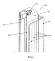
Figure 4 is a perspective view of the body fitted within a U-shaped housing; -
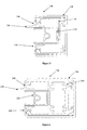
Figure 5 is a sectional view of the body fitted to a support bracket; -
Figure 6 is a sectional view of the body fitted to another support bracket; -
Figure 7 shows an end portion of the screen in a representative embodiment; and -
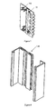
Figure 8 shows another representative embodiment of a support bracket. - A
blind system 100, as shown inFigure 1 , includes ascreen 102 with one end secured to arotatable roller 104 and another end secured to abar 106. Theroller 104 rotates in one direction to extend thescreen 102 over an area or opening of a building or equipment (e.g. a wall, window or skylight), and rotates in the other direction to retract thescreen 102. Theguide tracks 108 guide the movement of thescreen 102 andbar 106 during extension and retraction. Theroller 104 and theguide tracks 108 may be secured to a supporting frame, structure or surface. Thescreen 102 can be any flexible or rigid sheet material (e.g. canvas, fabric, wire or plastic mesh, or a panel) suitable for use as a cover. -
Figure 2 shows thebar 106 in greater detail. Anend portion 110 of thebar 106 has aguide portion 112 that is shaped to be received in a channel portion 124 (seeFigure 3 ) of theguide track 108. The flangedportion 114 floats on the outside theguide track 108. Thebar 106 also has aslot 116 that is adjustable to an open position (e.g. by turning one or more fasteners 118) for receiving an end of thescreen 102. Theslot 116 is adjustable to a closed position (e.g. by turning one or more fasteners 118) to form a secure engage between thebar 106 and end portion of thescreen 102 so as to resist detachment from each other. Thebar 106 may have sufficient weight to apply a downward force (due to gravity) to one end of thescreen 102. For applications where gravity does not play a role (e.g. skylights), thebar 106 may be pulled by other mechanical means (e.g. wire ropes secured to another rotatable roller). The extension and retraction of thescreen 102 may be mechanically triggered by pulling thebar 106, or by operating a separate controller (mechanical or electrical) that operates a mechanical drive device for driving the rotation of theroller 104 in a screen extending or screen retracting direction. -
Figure 3 shows a sectional view of a guide track 108 (along section A-A inFigure 1 ) for use in one representative embodiment of thesystem 100. Theguide track 108 includes a singlerigid body 120 that may be made as one piece. Theguide track 108 may include only thebody 120 or 300 (as described below), or a combination of thebody U-shaped housing 138 and/or abracket member 142 or 144). In a representative embodiment, thebody 120 is extruded from a rigid material (e.g. including a metal such as aluminium, or a polymer such as polyvinyl chloride (PVC)). Thebody 120 defines a guide channel for guiding the movement of thescreen 102 andbar 106 during extension and retraction of thescreen 102. The guide channel has a single longitudinal recess formed along thebody 120, and is divided into afirst channel portion 122 and asecond channel portion 124. The first andsecond channel portions body 120, and the first andsecond channel portions - The
body 120 also defines alongitudinal opening 126 that opens into thesecond channel portion 124. Aslit 128 is defined to provide access to thefirst channel portion 122 from thesecond channel portion 124. Theslit 128 may be defined by one ormore barrier members continuous wall section 136 of theguide track 108. -
Figure 3A shows a sectional view of anotherbody 300 for use as (or as part of) aguide track 108 of another representative embodiment of thesystem 100. Thebody 300 is assembled from two separate pieces, referred to as afirst member 302 and asecond member 304. Thefirst member 302 is shaped for securely coupling with thesecond member 304. For example, in the representative embodiment shown inFigure 3A , thefirst member 302 has arecess 306 shaped for engaging an outer surface of thesecond member 304 to resist separation from each other 302 and 304. The first andsecond members - The first and
second member respective barrier member slit 128. Thefirst member 302 may include one or more support portions 314 (e.g. in the form of projecting padded areas) for supporting different respective end portions of thesecond member 304 for correct lateral alignment of thebarrier members support portions 314 can help ensure that thebarrier members barrier members screen 102 moving along the slit 128). - The first and
second members members members slit 128 from becoming too small (and jam with the screen 102) or too large (and enable thescreen 102 to escape from the first channel portion 122) as the first andsecond members Figure 4 , thefirst member 302 includes arib 312 that protrudes into a corresponding recess formed in thesecond member 304. It will be understood that the first andsecond members - As shown in
Figure 3 , theguide portion 112 of thebar 106 is received into thesecond channel portion 124. Theguide portion 112 of thebar 106 is adapted for movement only within thesecond channel portion 124, so that thesecond channel portion 124 guides thebar 106 to move (or slide) along thelongitudinal opening 126 of theguide track 108. - As shown in
Figure 3 , thescreen 102 has an side portion 134 (also referred to as an edge portion) adapted to extend through thesecond channel portion 124, theslit 128 formed along theguide track 108, and then extend into thefirst channel portion 122. Theside portion 134 is also adapted so that thescreen 102 is able to move (or slide) along thefirst channel portion 122, and also adapted so that theside portion 134 is securely received within thefirst channel portion 122 to resist separation of theside portion 134 from thefirst channel portion 122. For example, a peripheral part of the side portion 134 (which is received within the first channel portion 122) may be adapted to have a greater size or diameter than the clearance (or size of the opening) of theslit 128 to resist theside portion 134 from being pulled out of thefirst channel portion 122 via theslit 128. - In a representative embodiment, the peripheral part of the
side portion 134 is made of a flexible material (e.g. a polymer-based material) with a low frictional coefficient relative to the material on the surface of thefirst channel portion 122, to which the peripheral part of theside portion 134 comes into contact (e.g. the surface of thebody 120, or any coating or substance applied thereon such as Teflon or silicon). - In a representative embodiment, the peripheral part of the
side portion 134 is one side of a zipper, which is typically used as a fastener in clothing. Thezipper side portion 134 may be sewn, glued or otherwise secured to the screen 102 (as shown inFigures 3 and7 ). It should be noted that thescreen 102 includes a sheet of material together with any other components attached or secured to that sheet of material (e.g. one or more zippers). - In a representative embodiment, the clearance of the slit 128 (i.e. the gap between the edges of the
body 120 that define the slit 128) is sufficiently small so that the respective edges defining theslit 128 are in close proximity to (e.g. just shy of touching) the surface of thescreen 102 passing through theslit 128. However, the clearance of theslit 128 is wide enough to allow thescreen 102 to move through (or slide along) theslit 128. In a representative embodiment, theslit 128 has a clearance of between 0.7 millimetres and 2.0 millimetres inclusive, which corresponds to an average thickness of materials that may be selected for use as ascreen 102. - As shown in
Figure 4 , thebody 120 can be fitted into aU-shaped housing 138. TheU-shaped housing 138 may be fixed to a supporting structure or surface (e.g. a wall or window frame). Thebody 120 is adjustably positioned within a recessed portion of theU-shaped housing 138 to ensure that sufficient tension is applied to the screen 102 (e.g. by stretching it taut, but not too much as to inhibit smooth sliding). TheU-shaped housing 138 may include one or more longitudinal recesses orgrooves 140. The recesses orgrooves 140 help align a fastener (e.g. a rivet) being driven through theU-shaped housing 138 to secure thebody 120 andhousing 138 together. The U-shaped housing may be made as one piece (as shown inFigure 4 ), or alternatively, may be made up of several pieces assembled together (as shown inFigure 8 ). Anend piece 152 may be fitted to the end of thebody 120 for guiding theside portion 134 of thescreen 102 into thesecond channel portion 122. For example, theend piece 152 shown inFigure 4 the two opposing sides of theslit 128 are spaced wider apart at an outward facing end of theend piece 152 and funnels towards the predefined clearance of theslit 128 at the inward facing end of theend piece 152. Theend piece 152 may be made of a rigid material (e.g. plastic or metal). -
Figures 5 and 6 show a sectional view of a representative embodiment where thebody 120 may be fitted to abracket member U-shaped housing 138. In other representative embodiments, the body 300 (or a body of other suitable design) may be used instead ofbody 120. Thebody 120 may be held in position relative to thebracket member more support members body 120. Asupport member 146 may be adapted to include aflanged portion 150, which helps deflect wind that flows towards thebody 120 and thus helps minimise the severity of the factors that may cause thescreen 102 to vibrate. - A key advantage of providing a
guide track 108 with abody 120 in the form of a single piece is that it is simpler (and therefore cost effective) to manufacture. Thebody guide track 108 can (at the same time) receive and hold onto theedges 134 of thescreen 102, as well as theend portions 110 of abar 106, so as to minimise the lateral movement of theseparts screen 102. This minimises the risk of damaging thescreen 102,bar 106 or adjacent items that may otherwise be struck by thescreen 102 or bar 106 as a result of excessive or intense lateral movement. - It can also be difficult to manufacture a
body 120 having aslit 128 with a very small clearance (e.g. just shy of touching the screen 102) but yet provide sufficient structural strength. Although metallic materials are generally difficult to shape, especially when a high degree of precision is required, the provision of the two different (or discrete) parallel first andsecond channel portions second channel portions bar 106 and thescreen 102 at the same time, as described above. When higher degrees of precision are required, thebody 300 can be manufactured from two ormore members members body 120 made as one piece. - Modifications and improvements to the invention will be readily apparent to those skilled in the art. Such modifications and improvements are intended to be within the scope of this invention.
- In this specification, including the background section, where a document, act or item of knowledge is referred to or discussed, this reference or discussion is not an admission that the document, act or item of knowledge or any combination thereof was at the priority date, publicly available, known to the public, part of common general knowledge, or known to be relevant to an attempt to solve any problem with which this specification is concerned.
Claims (5)
- A blind system, including:a screen with one end secured to a bar; anda guide track on opposite edges of said screen, each said guide track having a single rigid longitudinal body defining a guide channel with discrete parallel first and second channel portions;wherein, said screen has a edge portion extending through the second channel portion, a slit formed along said body, and into said first channel portion, for guiding the movement of said screen along said slit and for resisting separation of said edge portion from said first channel portion, and wherein said bar has an end portion adapted for movement only within said second channel portion for guiding said bar to move along said body.
- A system as claimed in claim 1, having one or more of the following characteristics:i) a said guide channel consisting of a single longitudinal recess formed in said body, said first and second portions being defined by a continuous wall section of said body; andii) a said body being extruded from a rigid material, and said slit providing access to said first channel portion from said second channel portion.
- A system as claimed in claim 1, wherein said slit is defined between two barrier members, said barrier members being positioned sufficiently close to respective front and back surfaces of said screen so as to: (i) allow said screen to slide along said slit, and (ii) minimise lateral movement of said screen between respective edges of said slit.
- A system as claimed in claim 3, wherein said slit has a clearance between 0.7 and 2.0 millimetres inclusive.
- A system as claimed in claim 1, wherein said side portion includes a peripheral portion located within said first channel portion, said peripheral portion having a cross-sectional size greater than a clearance of said slit so that said peripheral portion resists separation of said screen from said first channel portion.
Applications Claiming Priority (1)
| Application Number | Priority Date | Filing Date | Title |
|---|---|---|---|
| AU2009905294A AU2009905294A0 (en) | 2009-10-29 | A blind system |
Publications (2)
| Publication Number | Publication Date |
|---|---|
| EP2317062A1 true EP2317062A1 (en) | 2011-05-04 |
| EP2317062B1 EP2317062B1 (en) | 2012-10-03 |
Family
ID=42629435
Family Applications (1)
| Application Number | Title | Priority Date | Filing Date |
|---|---|---|---|
| EP10171721A Not-in-force EP2317062B1 (en) | 2009-10-29 | 2010-08-03 | A blind system |
Country Status (8)
| Country | Link |
|---|---|
| US (1) | US9371689B2 (en) |
| EP (1) | EP2317062B1 (en) |
| JP (1) | JP3163685U (en) |
| CN (1) | CN201786221U (en) |
| AU (1) | AU2010100720B4 (en) |
| ES (1) | ES2396438T3 (en) |
| NZ (1) | NZ587020A (en) |
| TW (1) | TWM402937U (en) |
Cited By (3)
| Publication number | Priority date | Publication date | Assignee | Title |
|---|---|---|---|---|
| EP3613619A1 (en) * | 2018-08-23 | 2020-02-26 | Inalfa Roof Systems Group B.V. | Guide rail for use in an open roof construction and open roof construction comprising such guide rail |
| NL2034066B1 (en) * | 2023-02-01 | 2024-08-23 | Van Der Valk Systemen B V | Device and method for extending a screen profile in a screen assembly |
| EP4624720A1 (en) | 2024-03-27 | 2025-10-01 | Griesser Holding AG | Guiding device for a side edge of a flexible sheet material of an awning and an awning comprising the same |
Families Citing this family (38)
| Publication number | Priority date | Publication date | Assignee | Title |
|---|---|---|---|---|
| CA2706496C (en) | 2009-06-09 | 2017-09-05 | Masonite Corporation | Track for an adjustable blind assembly |
| TWI499713B (en) * | 2009-11-06 | 2015-09-11 | Komatsu Denki Sangyo Kabushiki Kaisha | Sheet guide of sheet shutter |
| IT1404718B1 (en) * | 2011-02-25 | 2013-11-29 | Ct Gibus Srl | ROLLER SHUTTER SCREEN. |
| ITPD20110136A1 (en) * | 2011-05-02 | 2012-11-03 | Ct Gibus Srl | PROTECTION CURTAIN AND PROCEDURE FOR THE REALIZATION OF A PROTECTION TENT. |
| US20160319593A1 (en) * | 2011-05-11 | 2016-11-03 | Rajiva A. Dwarka | Retractable curtain panel with track guide |
| US20170009524A1 (en) * | 2011-05-11 | 2017-01-12 | Rajiva A. Dwarka | Retractable curtain panel and enhanced stiffeners |
| EP2757224B1 (en) * | 2011-06-24 | 2017-02-15 | Hayashiguchi Mfg Co., Ltd. | Roll screen device |
| NL2007194C2 (en) * | 2011-07-28 | 2013-01-29 | Unilux Nederland B V | Retractable and extendable covering device. |
| JP2013170390A (en) * | 2012-02-21 | 2013-09-02 | Ashimori Ind Co Ltd | Sheet guide for vehicle |
| GB2502039B (en) * | 2012-02-29 | 2017-11-15 | Ideas By Design Ltd | Apparatus for mounting a screen guide rail |
| JP5840981B2 (en) * | 2012-03-06 | 2016-01-06 | 芦森工業株式会社 | Shade device |
| WO2014009573A1 (en) * | 2012-07-11 | 2014-01-16 | Gaviota Simbac, S.L. | Structure for protection against the wind |
| CN102966295A (en) * | 2012-12-13 | 2013-03-13 | 上海米梁实业发展有限公司 | Invisible multifunctional window |
| WO2015176047A1 (en) * | 2014-05-15 | 2015-11-19 | Fleischman Jacob | Roll-up wall and acoustic barrier system |
| US10273750B2 (en) * | 2013-03-15 | 2019-04-30 | Jacob Fleischman | Roll-up wall system and modular components |
| WO2014145333A1 (en) * | 2013-03-15 | 2014-09-18 | Fleischman Jacob | Retractable wall system and adaptor components |
| US9428955B2 (en) * | 2013-03-15 | 2016-08-30 | Jacob Fleischman | Retractable wall system |
| BE1021781B1 (en) * | 2013-11-19 | 2016-01-18 | Renson Sunprotection-Screens Nv | COLUMN FOR SUPPORTING A COVER AND SCREEN CONSTRUCTION CONTAINING SUCH A COLUMN |
| JP6228504B2 (en) * | 2014-04-11 | 2017-11-08 | フクビ化学工業株式会社 | Screen device and manufacturing method thereof |
| JP6228506B2 (en) * | 2014-04-30 | 2017-11-08 | フクビ化学工業株式会社 | Screen device |
| DE102014107188A1 (en) * | 2014-05-21 | 2015-11-26 | Joachim Weber | High speed |
| EP2987667B1 (en) | 2014-08-18 | 2019-10-09 | Inalfa Roof Systems Group B.V. | Guide and sunshade assembly provided therewith |
| CN104453114B (en) * | 2014-12-05 | 2017-08-11 | 湖州恒怡节能科技有限公司 | A kind of frame of awning |
| WO2017123992A1 (en) * | 2016-01-13 | 2017-07-20 | Ciw Enterprises, Inc. | Roll-up doors and method for securing same |
| TWI708886B (en) * | 2016-03-30 | 2020-11-01 | 日商世紀販賣股份有限公司 | Roll screen device |
| US10309153B2 (en) * | 2016-09-26 | 2019-06-04 | Draper, Inc. | Support system for rolled material |
| US10260280B2 (en) | 2017-01-03 | 2019-04-16 | Mechoshade Systems, Llc | Systems and methods for roller blind channel coupling |
| US10253563B2 (en) | 2017-01-03 | 2019-04-09 | Mechoshade Systems, Llc | Base channel coupling |
| WO2018200875A1 (en) | 2017-04-26 | 2018-11-01 | Joel Klein | Modular roll-up wall system |
| US20190048658A1 (en) * | 2017-08-09 | 2019-02-14 | Professional Blinds System Inc. | Construction assembly for installing a roller blind or the like |
| BE1026543B1 (en) * | 2019-02-15 | 2020-03-10 | Renson Sunprotection Screens Nv | Side guide for screen layout |
| USD955141S1 (en) * | 2019-08-22 | 2022-06-21 | Bandalux Industrial, S.A. | Box roller shade assembly |
| USD955140S1 (en) * | 2019-08-22 | 2022-06-21 | Bandalux Industrial, S.A. | Box roller shade assembly |
| MX2023003931A (en) * | 2020-10-07 | 2023-04-26 | Pitt Ohio Express Llc | FRAME FOR LOADING DOCK DOOR, AND SYSTEM THAT INCLUDES THE SAME. |
| CN113417561B (en) * | 2021-07-23 | 2022-02-08 | 南京武家嘴门窗装饰有限公司 | External sunshade integrated system casement window |
| JP7751368B2 (en) * | 2022-01-31 | 2025-10-08 | 三協立山株式会社 | Screen device |
| CN115637918A (en) * | 2022-11-03 | 2023-01-24 | 山东浪潮超高清智能科技有限公司 | A rain-sensing outdoor large-screen rain-shielding system and method |
| US12584352B2 (en) * | 2023-04-05 | 2026-03-24 | Samuel Steinberg | Motorized door screen and shade assembly |
Citations (5)
| Publication number | Priority date | Publication date | Assignee | Title |
|---|---|---|---|---|
| AU598354B2 (en) | 1987-07-02 | 1990-06-21 | Seizo Hayashiguchi | Screen |
| US20040144498A1 (en) * | 2003-01-27 | 2004-07-29 | Hudoba Mark S. | Storm curtain apparatus |
| AU2002300183B2 (en) | 2001-07-23 | 2004-11-11 | Antonius Cornelis Maria De Maaijer | Track Guided Blind System |
| US20070006980A1 (en) * | 2005-07-08 | 2007-01-11 | Zabala Robert E | Roll up storm shutter slat connector retention system |
| AU2009212839A1 (en) * | 2008-08-29 | 2010-03-18 | Slidetrack Blinds Pty Ltd | Track guided blind system |
Family Cites Families (37)
| Publication number | Priority date | Publication date | Assignee | Title |
|---|---|---|---|---|
| US1959136A (en) * | 1933-09-20 | 1934-05-15 | Kinney I Miller | Window screen |
| US3292685A (en) * | 1963-09-09 | 1966-12-20 | Guaranteed Weather Inc | Weatherproof retractable wall |
| US4478268B1 (en) * | 1980-12-29 | 1991-04-23 | Door structure | |
| JPS61179989A (en) * | 1985-02-01 | 1986-08-12 | 林口 精三 | Shielding device for opening section of building and apparatus |
| DE8521854U1 (en) * | 1985-07-30 | 1985-09-12 | Seuster, Kurt, 5990 Altena | rolling gate |
| US4738296A (en) * | 1986-09-15 | 1988-04-19 | Bernard E. Hatch | Rolling steel door |
| US4759396A (en) * | 1987-05-11 | 1988-07-26 | The Scott & Fetzer Company | Lock mechanism for roll bar on retractable awning |
| US5332021A (en) * | 1991-09-11 | 1994-07-26 | Todd John M | Flexible retractable door |
| JP3105946B2 (en) | 1991-06-25 | 2000-11-06 | 松下電工株式会社 | Cord supply device |
| US5253694A (en) * | 1991-11-27 | 1993-10-19 | Bernardo Richard G | Rolling shutter slat end retainer |
| ATE241755T1 (en) * | 1994-04-29 | 2003-06-15 | Dynaco Internat | TERMINATION DEVICE WITH FLEXIBLE SCREEN |
| JPH09303068A (en) * | 1996-05-16 | 1997-11-25 | Hayashiguchi Kogyo Kk | Roll screen |
| US5839493A (en) * | 1997-02-14 | 1998-11-24 | Valco Enterprises, Ltd. | Rolling shutter and retention assembly |
| US6095224A (en) * | 1998-01-16 | 2000-08-01 | Miller; James V. | Shutter tracks for rolling protective shutters |
| US6302179B1 (en) * | 1998-01-16 | 2001-10-16 | James V. Miller | Modular roll-up partition system with tension adjustment mechanism |
| US6095225A (en) * | 1998-08-17 | 2000-08-01 | Miller; James V. | Shutter slat with integrated screw boss |
| JP2000303761A (en) * | 1999-04-19 | 2000-10-31 | Taiyo Kogyo Corp | Post for light-shielding screen |
| JP2000303781A (en) | 1999-04-21 | 2000-10-31 | Ishikawajima Harima Heavy Ind Co Ltd | Advanced shield equipment |
| US6260601B1 (en) * | 1999-12-23 | 2001-07-17 | Clopay Building Products R&D Company, Inc. | Wind-resistant coiling door |
| DE10022452A1 (en) * | 2000-05-09 | 2001-11-15 | Bautex Adolf Stoever Soehne Gm | Blind for a roller blind with side guide |
| US20020062930A1 (en) * | 2000-11-30 | 2002-05-30 | Isiah Jennings | Garage door screen apparatus |
| US6715529B2 (en) * | 2001-09-06 | 2004-04-06 | Humayoun Farooq | Rolling shutter assembly |
| US6631749B1 (en) * | 2002-05-22 | 2003-10-14 | Jaime Zabala | Wind resistant rolling shutter assembly |
| JP2004176473A (en) * | 2002-11-28 | 2004-06-24 | Hayashiguchi Kogyo Kk | Rolling screen |
| US20040188037A1 (en) * | 2003-03-31 | 2004-09-30 | Creative Extruded Products, Inc. | Retention system for pivotally connected shutter slats |
| CA2446648C (en) * | 2003-07-10 | 2005-03-29 | Tnr Industrial Doors Inc. | Roll-up flexible door and guides therefor |
| US20050082020A1 (en) * | 2003-10-21 | 2005-04-21 | Miller James V. | Reinforced shutter |
| US7100665B2 (en) * | 2004-03-17 | 2006-09-05 | Miller James V | Dual boss shutter slat with retention plate |
| US7357171B2 (en) * | 2004-03-17 | 2008-04-15 | Qmi Security Solutions | Low-clearance shutter slat |
| US7413000B2 (en) * | 2005-09-14 | 2008-08-19 | Macauto Industrial Co., Ltd. | Sun screen device |
| US20070175603A1 (en) * | 2006-01-27 | 2007-08-02 | Macauto Industrial Co., Ltd. | Sun screen device |
| US7748431B2 (en) * | 2006-06-05 | 2010-07-06 | Rite-Hite Holding Corporation | Track and guide system for a door |
| EP2003284A1 (en) * | 2007-06-13 | 2008-12-17 | Dynaco International S.A. | Device with a shutter and element for reinserting a shutter in a guide rail |
| US8490670B2 (en) * | 2009-01-22 | 2013-07-23 | Qualitas Manufacturing, Inc. | Build-out dowels for rolling protective shutters |
| US8235086B2 (en) * | 2009-09-14 | 2012-08-07 | Smith Richard C | System, method and apparatus for area screen coverage |
| USD631171S1 (en) * | 2010-01-28 | 2011-01-18 | Walter Martin Konrad | Rolling shutter side rail |
| US8291960B2 (en) * | 2010-04-15 | 2012-10-23 | Tnr Industrial Doors Inc. | Pivoting bottom bar for roll-up door |
-
2010
- 2010-07-07 AU AU2010100720A patent/AU2010100720B4/en not_active Expired
- 2010-07-27 NZ NZ587020A patent/NZ587020A/en not_active IP Right Cessation
- 2010-07-27 TW TW099214280U patent/TWM402937U/en not_active IP Right Cessation
- 2010-08-03 ES ES10171721T patent/ES2396438T3/en active Active
- 2010-08-03 EP EP10171721A patent/EP2317062B1/en not_active Not-in-force
- 2010-08-04 JP JP2010005212U patent/JP3163685U/en not_active Expired - Fee Related
- 2010-08-18 US US12/858,538 patent/US9371689B2/en active Active
- 2010-08-31 CN CN201020512622XU patent/CN201786221U/en not_active Expired - Lifetime
Patent Citations (5)
| Publication number | Priority date | Publication date | Assignee | Title |
|---|---|---|---|---|
| AU598354B2 (en) | 1987-07-02 | 1990-06-21 | Seizo Hayashiguchi | Screen |
| AU2002300183B2 (en) | 2001-07-23 | 2004-11-11 | Antonius Cornelis Maria De Maaijer | Track Guided Blind System |
| US20040144498A1 (en) * | 2003-01-27 | 2004-07-29 | Hudoba Mark S. | Storm curtain apparatus |
| US20070006980A1 (en) * | 2005-07-08 | 2007-01-11 | Zabala Robert E | Roll up storm shutter slat connector retention system |
| AU2009212839A1 (en) * | 2008-08-29 | 2010-03-18 | Slidetrack Blinds Pty Ltd | Track guided blind system |
Cited By (3)
| Publication number | Priority date | Publication date | Assignee | Title |
|---|---|---|---|---|
| EP3613619A1 (en) * | 2018-08-23 | 2020-02-26 | Inalfa Roof Systems Group B.V. | Guide rail for use in an open roof construction and open roof construction comprising such guide rail |
| NL2034066B1 (en) * | 2023-02-01 | 2024-08-23 | Van Der Valk Systemen B V | Device and method for extending a screen profile in a screen assembly |
| EP4624720A1 (en) | 2024-03-27 | 2025-10-01 | Griesser Holding AG | Guiding device for a side edge of a flexible sheet material of an awning and an awning comprising the same |
Also Published As
| Publication number | Publication date |
|---|---|
| US20110100570A1 (en) | 2011-05-05 |
| EP2317062B1 (en) | 2012-10-03 |
| CN201786221U (en) | 2011-04-06 |
| AU2010100720B4 (en) | 2011-09-08 |
| TWM402937U (en) | 2011-05-01 |
| NZ587020A (en) | 2011-03-31 |
| US9371689B2 (en) | 2016-06-21 |
| JP3163685U (en) | 2010-10-28 |
| AU2010100720A4 (en) | 2010-08-05 |
| ES2396438T3 (en) | 2013-02-21 |
Similar Documents
| Publication | Publication Date | Title |
|---|---|---|
| AU2010100720A4 (en) | A blind system | |
| CN107075903B (en) | Retrofit retractable screen system | |
| AU2017268645B2 (en) | Upper guide track and assembly for a retractable screen | |
| US9670721B2 (en) | Guide arrangement for hangings | |
| EP2402544B1 (en) | Blind with looped blind sheet for adjusting opacity | |
| EP2633146A1 (en) | Window screen device | |
| US6186215B1 (en) | Multi-positional rolling window screen | |
| KR101871766B1 (en) | Roll-Type Insect Net Apparatus | |
| EP2487316B1 (en) | Screen apparatus | |
| EP2949857A1 (en) | Window screen with blind function | |
| EP2236731B1 (en) | Covering arrangement for architectural openings | |
| KR200469501Y1 (en) | Blind support apparatus for Fabric tention system | |
| AU2016100134A4 (en) | A blind system | |
| KR200476979Y1 (en) | Shading device having structure for preventing screen sagging | |
| US20080099165A1 (en) | Method and apparatus for window covering with a cord safety device | |
| KR20110004507U (en) | Blind system | |
| CN102678034B (en) | Roller blind and method for adjusting same | |
| KR20160003480U (en) | electromotion type roll blind with tension device | |
| US9057219B1 (en) | Window covering with integrated side track | |
| KR101885268B1 (en) | Roll screen system having airproof | |
| JP4368907B2 (en) | Pet entrance / exit sheet | |
| CA2618842C (en) | Cordless flexible window covering | |
| RU103060U1 (en) | ANTI-MOSCOW MESH FASTENING WITH WELCOME TAPES | |
| JP2007063943A (en) | Screen opening/closing device and its method |
Legal Events
| Date | Code | Title | Description |
|---|---|---|---|
| PUAI | Public reference made under article 153(3) epc to a published international application that has entered the european phase |
Free format text: ORIGINAL CODE: 0009012 |
|
| AK | Designated contracting states |
Kind code of ref document: A1 Designated state(s): AL AT BE BG CH CY CZ DE DK EE ES FI FR GB GR HR HU IE IS IT LI LT LU LV MC MK MT NL NO PL PT RO SE SI SK SM TR |
|
| AX | Request for extension of the european patent |
Extension state: BA ME RS |
|
| 17P | Request for examination filed |
Effective date: 20111104 |
|
| 17Q | First examination report despatched |
Effective date: 20111128 |
|
| GRAP | Despatch of communication of intention to grant a patent |
Free format text: ORIGINAL CODE: EPIDOSNIGR1 |
|
| GRAS | Grant fee paid |
Free format text: ORIGINAL CODE: EPIDOSNIGR3 |
|
| GRAA | (expected) grant |
Free format text: ORIGINAL CODE: 0009210 |
|
| AK | Designated contracting states |
Kind code of ref document: B1 Designated state(s): AL AT BE BG CH CY CZ DE DK EE ES FI FR GB GR HR HU IE IS IT LI LT LU LV MC MK MT NL NO PL PT RO SE SI SK SM TR |
|
| REG | Reference to a national code |
Ref country code: GB Ref legal event code: FG4D |
|
| REG | Reference to a national code |
Ref country code: AT Ref legal event code: REF Ref document number: 578077 Country of ref document: AT Kind code of ref document: T Effective date: 20121015 Ref country code: CH Ref legal event code: EP |
|
| REG | Reference to a national code |
Ref country code: IE Ref legal event code: FG4D |
|
| REG | Reference to a national code |
Ref country code: DE Ref legal event code: R096 Ref document number: 602010003043 Country of ref document: DE Effective date: 20121129 |
|
| REG | Reference to a national code |
Ref country code: NL Ref legal event code: T3 |
|
| REG | Reference to a national code |
Ref country code: AT Ref legal event code: MK05 Ref document number: 578077 Country of ref document: AT Kind code of ref document: T Effective date: 20121003 |
|
| REG | Reference to a national code |
Ref country code: ES Ref legal event code: FG2A Ref document number: 2396438 Country of ref document: ES Kind code of ref document: T3 Effective date: 20130221 |
|
| PG25 | Lapsed in a contracting state [announced via postgrant information from national office to epo] |
Ref country code: SI Free format text: LAPSE BECAUSE OF FAILURE TO SUBMIT A TRANSLATION OF THE DESCRIPTION OR TO PAY THE FEE WITHIN THE PRESCRIBED TIME-LIMIT Effective date: 20121003 |
|
| REG | Reference to a national code |
Ref country code: LT Ref legal event code: MG4D |
|
| PG25 | Lapsed in a contracting state [announced via postgrant information from national office to epo] |
Ref country code: LT Free format text: LAPSE BECAUSE OF FAILURE TO SUBMIT A TRANSLATION OF THE DESCRIPTION OR TO PAY THE FEE WITHIN THE PRESCRIBED TIME-LIMIT Effective date: 20121003 Ref country code: SE Free format text: LAPSE BECAUSE OF FAILURE TO SUBMIT A TRANSLATION OF THE DESCRIPTION OR TO PAY THE FEE WITHIN THE PRESCRIBED TIME-LIMIT Effective date: 20121003 Ref country code: FI Free format text: LAPSE BECAUSE OF FAILURE TO SUBMIT A TRANSLATION OF THE DESCRIPTION OR TO PAY THE FEE WITHIN THE PRESCRIBED TIME-LIMIT Effective date: 20121003 Ref country code: HR Free format text: LAPSE BECAUSE OF FAILURE TO SUBMIT A TRANSLATION OF THE DESCRIPTION OR TO PAY THE FEE WITHIN THE PRESCRIBED TIME-LIMIT Effective date: 20121003 Ref country code: NO Free format text: LAPSE BECAUSE OF FAILURE TO SUBMIT A TRANSLATION OF THE DESCRIPTION OR TO PAY THE FEE WITHIN THE PRESCRIBED TIME-LIMIT Effective date: 20130103 Ref country code: IS Free format text: LAPSE BECAUSE OF FAILURE TO SUBMIT A TRANSLATION OF THE DESCRIPTION OR TO PAY THE FEE WITHIN THE PRESCRIBED TIME-LIMIT Effective date: 20130203 |
|
| PG25 | Lapsed in a contracting state [announced via postgrant information from national office to epo] |
Ref country code: PL Free format text: LAPSE BECAUSE OF FAILURE TO SUBMIT A TRANSLATION OF THE DESCRIPTION OR TO PAY THE FEE WITHIN THE PRESCRIBED TIME-LIMIT Effective date: 20121003 Ref country code: GR Free format text: LAPSE BECAUSE OF FAILURE TO SUBMIT A TRANSLATION OF THE DESCRIPTION OR TO PAY THE FEE WITHIN THE PRESCRIBED TIME-LIMIT Effective date: 20130104 Ref country code: LV Free format text: LAPSE BECAUSE OF FAILURE TO SUBMIT A TRANSLATION OF THE DESCRIPTION OR TO PAY THE FEE WITHIN THE PRESCRIBED TIME-LIMIT Effective date: 20121003 Ref country code: BE Free format text: LAPSE BECAUSE OF FAILURE TO SUBMIT A TRANSLATION OF THE DESCRIPTION OR TO PAY THE FEE WITHIN THE PRESCRIBED TIME-LIMIT Effective date: 20121003 Ref country code: PT Free format text: LAPSE BECAUSE OF FAILURE TO SUBMIT A TRANSLATION OF THE DESCRIPTION OR TO PAY THE FEE WITHIN THE PRESCRIBED TIME-LIMIT Effective date: 20130204 |
|
| PG25 | Lapsed in a contracting state [announced via postgrant information from national office to epo] |
Ref country code: AT Free format text: LAPSE BECAUSE OF FAILURE TO SUBMIT A TRANSLATION OF THE DESCRIPTION OR TO PAY THE FEE WITHIN THE PRESCRIBED TIME-LIMIT Effective date: 20121003 |
|
| PG25 | Lapsed in a contracting state [announced via postgrant information from national office to epo] |
Ref country code: CZ Free format text: LAPSE BECAUSE OF FAILURE TO SUBMIT A TRANSLATION OF THE DESCRIPTION OR TO PAY THE FEE WITHIN THE PRESCRIBED TIME-LIMIT Effective date: 20121003 Ref country code: SK Free format text: LAPSE BECAUSE OF FAILURE TO SUBMIT A TRANSLATION OF THE DESCRIPTION OR TO PAY THE FEE WITHIN THE PRESCRIBED TIME-LIMIT Effective date: 20121003 Ref country code: DK Free format text: LAPSE BECAUSE OF FAILURE TO SUBMIT A TRANSLATION OF THE DESCRIPTION OR TO PAY THE FEE WITHIN THE PRESCRIBED TIME-LIMIT Effective date: 20121003 Ref country code: BG Free format text: LAPSE BECAUSE OF FAILURE TO SUBMIT A TRANSLATION OF THE DESCRIPTION OR TO PAY THE FEE WITHIN THE PRESCRIBED TIME-LIMIT Effective date: 20130103 Ref country code: EE Free format text: LAPSE BECAUSE OF FAILURE TO SUBMIT A TRANSLATION OF THE DESCRIPTION OR TO PAY THE FEE WITHIN THE PRESCRIBED TIME-LIMIT Effective date: 20121003 |
|
| PLBE | No opposition filed within time limit |
Free format text: ORIGINAL CODE: 0009261 |
|
| STAA | Information on the status of an ep patent application or granted ep patent |
Free format text: STATUS: NO OPPOSITION FILED WITHIN TIME LIMIT |
|
| PG25 | Lapsed in a contracting state [announced via postgrant information from national office to epo] |
Ref country code: RO Free format text: LAPSE BECAUSE OF FAILURE TO SUBMIT A TRANSLATION OF THE DESCRIPTION OR TO PAY THE FEE WITHIN THE PRESCRIBED TIME-LIMIT Effective date: 20121003 |
|
| 26N | No opposition filed |
Effective date: 20130704 |
|
| REG | Reference to a national code |
Ref country code: DE Ref legal event code: R097 Ref document number: 602010003043 Country of ref document: DE Effective date: 20130704 |
|
| PG25 | Lapsed in a contracting state [announced via postgrant information from national office to epo] |
Ref country code: CY Free format text: LAPSE BECAUSE OF FAILURE TO SUBMIT A TRANSLATION OF THE DESCRIPTION OR TO PAY THE FEE WITHIN THE PRESCRIBED TIME-LIMIT Effective date: 20121003 |
|
| PG25 | Lapsed in a contracting state [announced via postgrant information from national office to epo] |
Ref country code: MC Free format text: LAPSE BECAUSE OF FAILURE TO SUBMIT A TRANSLATION OF THE DESCRIPTION OR TO PAY THE FEE WITHIN THE PRESCRIBED TIME-LIMIT Effective date: 20121003 |
|
| REG | Reference to a national code |
Ref country code: IE Ref legal event code: MM4A |
|
| PG25 | Lapsed in a contracting state [announced via postgrant information from national office to epo] |
Ref country code: IE Free format text: LAPSE BECAUSE OF NON-PAYMENT OF DUE FEES Effective date: 20130803 |
|
| REG | Reference to a national code |
Ref country code: CH Ref legal event code: PL |
|
| PG25 | Lapsed in a contracting state [announced via postgrant information from national office to epo] |
Ref country code: LI Free format text: LAPSE BECAUSE OF NON-PAYMENT OF DUE FEES Effective date: 20140831 Ref country code: CH Free format text: LAPSE BECAUSE OF NON-PAYMENT OF DUE FEES Effective date: 20140831 |
|
| PG25 | Lapsed in a contracting state [announced via postgrant information from national office to epo] |
Ref country code: SM Free format text: LAPSE BECAUSE OF FAILURE TO SUBMIT A TRANSLATION OF THE DESCRIPTION OR TO PAY THE FEE WITHIN THE PRESCRIBED TIME-LIMIT Effective date: 20121003 |
|
| REG | Reference to a national code |
Ref country code: DE Ref legal event code: R082 Ref document number: 602010003043 Country of ref document: DE Representative=s name: WITTE, WELLER & PARTNER PATENTANWAELTE MBB, DE Ref country code: DE Ref legal event code: R081 Ref document number: 602010003043 Country of ref document: DE Owner name: ACMEDA PTY. LTD., BROADMEADOWS, AU Free format text: FORMER OWNER: LICCIARDI DI STEFANO, CARMELO JOSEPH, BROADMEADOWS, AU Ref country code: DE Ref legal event code: R081 Ref document number: 602010003043 Country of ref document: DE Owner name: ACMEDA PTY. LTD., BROADMEADOWS, AU Free format text: FORMER OWNER: LICCIARDI DI STEFANO, CARMELO JOSEPH, BROADMEADOWS, VIC, AU |
|
| PG25 | Lapsed in a contracting state [announced via postgrant information from national office to epo] |
Ref country code: MT Free format text: LAPSE BECAUSE OF FAILURE TO SUBMIT A TRANSLATION OF THE DESCRIPTION OR TO PAY THE FEE WITHIN THE PRESCRIBED TIME-LIMIT Effective date: 20121003 Ref country code: TR Free format text: LAPSE BECAUSE OF FAILURE TO SUBMIT A TRANSLATION OF THE DESCRIPTION OR TO PAY THE FEE WITHIN THE PRESCRIBED TIME-LIMIT Effective date: 20121003 |
|
| PG25 | Lapsed in a contracting state [announced via postgrant information from national office to epo] |
Ref country code: HU Free format text: LAPSE BECAUSE OF FAILURE TO SUBMIT A TRANSLATION OF THE DESCRIPTION OR TO PAY THE FEE WITHIN THE PRESCRIBED TIME-LIMIT; INVALID AB INITIO Effective date: 20100803 Ref country code: LU Free format text: LAPSE BECAUSE OF NON-PAYMENT OF DUE FEES Effective date: 20130803 Ref country code: MK Free format text: LAPSE BECAUSE OF FAILURE TO SUBMIT A TRANSLATION OF THE DESCRIPTION OR TO PAY THE FEE WITHIN THE PRESCRIBED TIME-LIMIT Effective date: 20121003 |
|
| REG | Reference to a national code |
Ref country code: FR Ref legal event code: TP Owner name: ACMEDA PTY LTD, AU Effective date: 20150626 |
|
| REG | Reference to a national code |
Ref country code: ES Ref legal event code: PC2A Owner name: ACMEDA PTY LTD Effective date: 20150731 |
|
| REG | Reference to a national code |
Ref country code: GB Ref legal event code: 732E Free format text: REGISTERED BETWEEN 20151001 AND 20151007 |
|
| REG | Reference to a national code |
Ref country code: NL Ref legal event code: PD Owner name: ACMEDA PTY LTD ACN 602 498 395; AU Free format text: DETAILS ASSIGNMENT: VERANDERING VAN EIGENAAR(S), OVERDRACHT; FORMER OWNER NAME: LICCIARDI DI STEFANO, CARMELO JOSEPH Effective date: 20150814 |
|
| REG | Reference to a national code |
Ref country code: FR Ref legal event code: PLFP Year of fee payment: 7 |
|
| REG | Reference to a national code |
Ref country code: FR Ref legal event code: PLFP Year of fee payment: 8 |
|
| REG | Reference to a national code |
Ref country code: FR Ref legal event code: PLFP Year of fee payment: 9 |
|
| PG25 | Lapsed in a contracting state [announced via postgrant information from national office to epo] |
Ref country code: AL Free format text: LAPSE BECAUSE OF FAILURE TO SUBMIT A TRANSLATION OF THE DESCRIPTION OR TO PAY THE FEE WITHIN THE PRESCRIBED TIME-LIMIT Effective date: 20121003 |
|
| PGFP | Annual fee paid to national office [announced via postgrant information from national office to epo] |
Ref country code: ES Payment date: 20180904 Year of fee payment: 9 Ref country code: DE Payment date: 20180829 Year of fee payment: 9 Ref country code: IT Payment date: 20180822 Year of fee payment: 9 Ref country code: NL Payment date: 20180826 Year of fee payment: 9 Ref country code: FR Payment date: 20180827 Year of fee payment: 9 |
|
| PGFP | Annual fee paid to national office [announced via postgrant information from national office to epo] |
Ref country code: GB Payment date: 20180828 Year of fee payment: 9 |
|
| REG | Reference to a national code |
Ref country code: DE Ref legal event code: R119 Ref document number: 602010003043 Country of ref document: DE |
|
| REG | Reference to a national code |
Ref country code: NL Ref legal event code: MM Effective date: 20190901 |
|
| GBPC | Gb: european patent ceased through non-payment of renewal fee |
Effective date: 20190803 |
|
| PG25 | Lapsed in a contracting state [announced via postgrant information from national office to epo] |
Ref country code: NL Free format text: LAPSE BECAUSE OF NON-PAYMENT OF DUE FEES Effective date: 20190901 Ref country code: FR Free format text: LAPSE BECAUSE OF NON-PAYMENT OF DUE FEES Effective date: 20190831 Ref country code: DE Free format text: LAPSE BECAUSE OF NON-PAYMENT OF DUE FEES Effective date: 20200303 |
|
| PG25 | Lapsed in a contracting state [announced via postgrant information from national office to epo] |
Ref country code: GB Free format text: LAPSE BECAUSE OF NON-PAYMENT OF DUE FEES Effective date: 20190803 Ref country code: IT Free format text: LAPSE BECAUSE OF NON-PAYMENT OF DUE FEES Effective date: 20190803 |
|
| REG | Reference to a national code |
Ref country code: ES Ref legal event code: FD2A Effective date: 20210105 |
|
| PG25 | Lapsed in a contracting state [announced via postgrant information from national office to epo] |
Ref country code: ES Free format text: LAPSE BECAUSE OF NON-PAYMENT OF DUE FEES Effective date: 20190804 |