EP2315503B2 - Method and system for allocating operating addresses to light sources or lights - Google Patents
Method and system for allocating operating addresses to light sources or lights Download PDFInfo
- Publication number
- EP2315503B2 EP2315503B2 EP10188877.4A EP10188877A EP2315503B2 EP 2315503 B2 EP2315503 B2 EP 2315503B2 EP 10188877 A EP10188877 A EP 10188877A EP 2315503 B2 EP2315503 B2 EP 2315503B2
- Authority
- EP
- European Patent Office
- Prior art keywords
- optical signals
- lights
- light
- light sources
- evaluating
- Prior art date
- Legal status (The legal status is an assumption and is not a legal conclusion. Google has not performed a legal analysis and makes no representation as to the accuracy of the status listed.)
- Active
Links
- 238000000034 method Methods 0.000 title claims description 33
- 230000003287 optical effect Effects 0.000 claims description 77
- 238000003909 pattern recognition Methods 0.000 claims description 7
- 238000012545 processing Methods 0.000 claims description 6
- 238000012800 visualization Methods 0.000 claims description 3
- 238000005286 illumination Methods 0.000 claims 9
- 230000006854 communication Effects 0.000 description 17
- 238000004891 communication Methods 0.000 description 17
- 238000011161 development Methods 0.000 description 8
- 230000018109 developmental process Effects 0.000 description 8
- 238000001514 detection method Methods 0.000 description 7
- 238000011156 evaluation Methods 0.000 description 5
- 238000013461 design Methods 0.000 description 3
- 238000009434 installation Methods 0.000 description 3
- 238000012937 correction Methods 0.000 description 2
- 230000010354 integration Effects 0.000 description 2
- 230000004913 activation Effects 0.000 description 1
- 230000007175 bidirectional communication Effects 0.000 description 1
- 230000008859 change Effects 0.000 description 1
- 230000009849 deactivation Effects 0.000 description 1
- 230000001419 dependent effect Effects 0.000 description 1
- 230000007717 exclusion Effects 0.000 description 1
- 238000010191 image analysis Methods 0.000 description 1
- 230000006872 improvement Effects 0.000 description 1
- 230000000977 initiatory effect Effects 0.000 description 1
- 230000003993 interaction Effects 0.000 description 1
- 238000012544 monitoring process Methods 0.000 description 1
- 238000003672 processing method Methods 0.000 description 1
- 230000011218 segmentation Effects 0.000 description 1
- 230000003595 spectral effect Effects 0.000 description 1
Images

Classifications
-
- H—ELECTRICITY
- H05—ELECTRIC TECHNIQUES NOT OTHERWISE PROVIDED FOR
- H05B—ELECTRIC HEATING; ELECTRIC LIGHT SOURCES NOT OTHERWISE PROVIDED FOR; CIRCUIT ARRANGEMENTS FOR ELECTRIC LIGHT SOURCES, IN GENERAL
- H05B47/00—Circuit arrangements for operating light sources in general, i.e. where the type of light source is not relevant
- H05B47/10—Controlling the light source
- H05B47/175—Controlling the light source by remote control
- H05B47/18—Controlling the light source by remote control via data-bus transmission
-
- H—ELECTRICITY
- H04—ELECTRIC COMMUNICATION TECHNIQUE
- H04L—TRANSMISSION OF DIGITAL INFORMATION, e.g. TELEGRAPHIC COMMUNICATION
- H04L61/00—Network arrangements, protocols or services for addressing or naming
- H04L61/50—Address allocation
- H04L61/5038—Address allocation for local use, e.g. in LAN or USB networks, or in a controller area network [CAN]
-
- H—ELECTRICITY
- H05—ELECTRIC TECHNIQUES NOT OTHERWISE PROVIDED FOR
- H05B—ELECTRIC HEATING; ELECTRIC LIGHT SOURCES NOT OTHERWISE PROVIDED FOR; CIRCUIT ARRANGEMENTS FOR ELECTRIC LIGHT SOURCES, IN GENERAL
- H05B47/00—Circuit arrangements for operating light sources in general, i.e. where the type of light source is not relevant
- H05B47/10—Controlling the light source
- H05B47/175—Controlling the light source by remote control
- H05B47/198—Grouping of control procedures or address assignation to light sources
- H05B47/199—Commissioning of light sources
-
- H—ELECTRICITY
- H05—ELECTRIC TECHNIQUES NOT OTHERWISE PROVIDED FOR
- H05B—ELECTRIC HEATING; ELECTRIC LIGHT SOURCES NOT OTHERWISE PROVIDED FOR; CIRCUIT ARRANGEMENTS FOR ELECTRIC LIGHT SOURCES, IN GENERAL
- H05B47/00—Circuit arrangements for operating light sources in general, i.e. where the type of light source is not relevant
- H05B47/10—Controlling the light source
- H05B47/175—Controlling the light source by remote control
- H05B47/18—Controlling the light source by remote control via data-bus transmission
- H05B47/183—Controlling the light source by remote control via data-bus transmission using digital addressable lighting interface [DALI] communication protocols
-
- H—ELECTRICITY
- H05—ELECTRIC TECHNIQUES NOT OTHERWISE PROVIDED FOR
- H05B—ELECTRIC HEATING; ELECTRIC LIGHT SOURCES NOT OTHERWISE PROVIDED FOR; CIRCUIT ARRANGEMENTS FOR ELECTRIC LIGHT SOURCES, IN GENERAL
- H05B47/00—Circuit arrangements for operating light sources in general, i.e. where the type of light source is not relevant
- H05B47/10—Controlling the light source
- H05B47/175—Controlling the light source by remote control
- H05B47/18—Controlling the light source by remote control via data-bus transmission
- H05B47/184—Controlling the light source by remote control via data-bus transmission using digital multiplexed [DMX] communication protocols
-
- H—ELECTRICITY
- H05—ELECTRIC TECHNIQUES NOT OTHERWISE PROVIDED FOR
- H05B—ELECTRIC HEATING; ELECTRIC LIGHT SOURCES NOT OTHERWISE PROVIDED FOR; CIRCUIT ARRANGEMENTS FOR ELECTRIC LIGHT SOURCES, IN GENERAL
- H05B47/00—Circuit arrangements for operating light sources in general, i.e. where the type of light source is not relevant
- H05B47/10—Controlling the light source
- H05B47/175—Controlling the light source by remote control
- H05B47/196—Controlling the light source by remote control characterised by user interface arrangements
Definitions
- the present invention relates to a method and a system for assigning operating addresses for light sources or luminaires which are part of a lighting or media system.
- Modern and complex buildings have extensive means of managing and monitoring the facilities of the building. On the one hand, this results in increased comfort for the residents or users if as many operational functions to be coordinated as possible are controlled with the support of control devices; Extensively controllable lighting systems are provided especially in complex buildings such as hospitals, airports or other public buildings. Particularly when media or control systems that can be used variably are added, the question of flexibly and cost-effectively changeable systems is inevitable.
- central control units for control and regulation has become established for complex lighting systems or media systems, with the help of which the wiring effort is reduced and the systems can be used and expanded flexibly.
- a central control unit usually has a connection to a bus system which enables the remote control and regulation of a light source or lamp in a system of the type described.
- An individual original address assigned to each separately controllable light source which is sufficiently complex to ensure uniqueness, is generally used for communication with a light source.
- the establishment addresses are usually established before or during the installation of the lighting system.
- a common method for assigning company addresses provides for a single light source of the lighting system to be caused to emit a signal. The installation staff must then determine which light source emitted the signal. This light source is then assigned an operating address that corresponds to the lighting system concept. This is repeated until each separately controllable light source of the lighting system has received a suitable operating address.
- the object of the present invention is to improve and simplify a method for assigning company addresses.
- the method according to the invention for assigning operating addresses for light sources or luminaires which are part of a lighting or media system provides that a control unit contacts a light source or luminaire using an original address assigned to the light source or luminaire. Furthermore, the control unit causes the light source or lamp to identify itself by emitting an optical signal. The position of the identifying light source or lamp is then recorded. This takes place with the aid of means for detecting optical signals, which generate information or a signal, and further with the aid of means for evaluating this information or this signal. On the basis of the position thus detected and in accordance with a reference scheme of the lighting or media system, which contains an assignment of an operating address to a light source position or lamp position, the control unit now assigns an operating address to the light source or lamp.
- the steps - contacting, identifying, recording the position and assigning the operating address - can now be carried out for each light source or lamp that is intended to receive an operating address.
- the means for capturing optical signals have a camera and the means for evaluating the captured optical signal are means for image processing.
- the means for evaluating the detected optical signals have means for pattern recognition.
- the method additionally has the following steps: the control unit contacts all light sources or lights and causes them to emit an optical signal; with the aid of the means for detecting optical signals, reference information is generated which includes the full signal information of the lighting or media system; The number and position of the light sources or lamps is determined from the full signal information with the aid of the means for evaluating the detected optical signals; Using the reference information, the reference scheme of the lighting or media system is created, which contains the assignment of an operating address to a light source position or luminaire position.
- an addressing system which has a control unit which is designed to individually contact the light sources or lamps using original addresses assigned to the light sources or lamps and to cause them to identify themselves by emitting an optical signal.
- the addressing system has means for capturing optical signals from the identifying light source or lamp as well as means for evaluating the captured optical signals, which are designed to determine the position of an identifying light source or lamp by evaluating the captured optical signal.
- the control unit is designed to assign an operating address based on the position of the light source or lamp determined by the means for evaluating optical signals and according to a reference scheme of the lighting or media system, which contains an assignment of an operating address to a light source position or lamp position.
- the means for acquiring an optical signal have a camera and the means for evaluating the acquired optical signal are means for image processing.
- the means for evaluating the detected optical signals have means for pattern recognition. Before the control unit contacts the light sources or lights individually, the control unit is also designed to contact all light sources or lights and to cause them to emit an optical signal; the means for acquiring optical signals are also designed to generate reference information which includes the full signal information of the lighting or media system; the means for evaluating the detected optical signals are also designed to determine the number and position of the light sources or lights from the full signal information; and the means for evaluating the detected optical signals are also designed to use the reference information to create the reference scheme of the lighting or media system, which contains the assignment of an operating address to a light source position or lamp position.
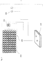
- Figure 1 shows a complex media system 240 with a multiplicity of LED light sources 220, which can be controlled individually via a system controller. It is provided that the operating state of the LEDs is controlled individually; for example, in addition to activation or deactivation, in particular a change in the brightness or color of the LED light sources can be provided.
- the media system could be intended to display advertising, for example.
- the advertising message In order to display the advertising message quickly and flexibly, it makes sense to assign an operating address to each of these multitudes of LEDs 220 for communication with the system control - in particular to improve the individual controllability, this operating address taking into account in particular the position of the associated LED 220 in the arrangement.
- a manual assignment of the operating addresses is very time-consuming and ineffective with this large number of light sources 220 or luminaires 200. With the aid of an addressing system 1 according to the invention, however, this can be made enormous easier and automated.
- a control unit 100 is provided which is designed to contact the LED light sources 220 individually using the original addresses assigned to the light sources 220 and to cause them to identify themselves by emitting an optical signal.
- the optical signal can consist in the fact that the contacted LED is activated or deactivated.
- the addressing system 1 also has means for detecting optical signals 300 of the media system.
- this is a camera 300, which is preferably designed to convert, preferably digitize, an optical signal into an electrical signal or a sequence of electrical signals.
- the addressing system 1 also has means for evaluating the detected optical signals, which are designed to determine the position of an identifying LED light source 220 by evaluating the detected optical signal. This is for an illustration of the LED light sources 220 by a camera 300 is possible in a particularly simple manner, since the geometric position can be determined directly from the position of the contacted LED in the image, and particularly advantageous algorithms for determining the position, such as image processing methods, can be used.
- control unit 100 is designed to assign an operating address to the LEDs on the basis of the position of the LEDs determined by the means for evaluating the detected optical signals.
- the LEDs are controlled via a control element 210 of the media system, which is designed to control each LED individually and to reproduce an original address for each individually controllable LED, as well as to receive an operating address for each LED light source of the media system 240.
- the geometric position of the LEDs is preferably mapped in the assigned operating address; for example, the operating address can then also contain coordinate information which corresponds to a position of an LED in a row or column of the media system 240. This represents a possibility of suitably defining an operating address in a particularly simple manner.
- a media system In addition to the assignment of company addresses for a media system, it can also be used for a large number of lighting and / or media systems. For example, it could be a lighting system integrated into a wall or facade of a house or building with a large number of light sources or lights. These can be used to display information as in the case of the exemplary embodiment from Figure 1 media system described serve and / or general lighting purposes are sufficient. For example, a company address for a wall of this type could be assigned with minimal system effort by just one camera. In more complex building sections or with a lighting system that extends over several rooms, the use of several cameras can be particularly useful.
- a control unit 100 contacts a light source 220 or lamp. The contact is made with the aid of an original address assigned to the light source 220 or lamp 200, which is known to the control unit 100 before the method according to the invention is started.
- the control unit 100 could previously, by means of bidirectional communication with control elements 210, first send a request to all light sources 220 or luminaires 200 to communicate their original addresses and then save the information received.
- this original address can be a device-specific address that is uniquely coded by the manufacturer of the light source 220 or lamp 200 during production.
- an original address generated at random - e.g. similar to the DALI standard is known to the control unit 100 before the start of the method according to the invention for assigning an operating address.
- the control unit 100 makes contact with the light source 220 or lamp 200 and causes an optical signal to be emitted.
- the signal output of the light source 220 or lamp 200 can consist in switching the light source 220 or lamp 200 on or off or dimming it.
- the signal output is preferably adapted to the control and regulation options of a control unit 210, which controls and regulates the operating state of a light source 220 lamp 200.
- the position of the identifying light source 220 or lamp 200 is detected with the aid of means for detecting optical signals 300 and with the aid of means for evaluating the detected optical signals.
- the detected position is preferably the geometric position of a light source 220 or lamp 200 relative to an origin point. It can be advantageous to provide several points of origin, which are characterized, for example, by their location in different rooms or parts of buildings or also lights or media systems. In particular, various design variants of the position information are conceivable, which - as explained below - are primarily due to the means for detecting an optical signal or their interaction.
- control unit 100 assigns an operating address to the light source 220 or luminaire 200 caused to emit signals.
- the steps - contacting, initiating an optical signal output, acquiring an optical signal, evaluating the acquired signal, determining the position, as well as assigning an operating address based on the position - can now be repeated one after the other for other light sources 220 or lights 200 until until each light source 220 or lamp 200 provided for receiving an operating address has a suitable operating address.
- control unit 100 with the means for detecting optical signals 300 takes place via the communication network of the lighting or media system.
- the control unit 100 has, however, a separate one from the connection of the light sources 220 or lights 200 in the illustrated embodiment Interface on.
- the detected optical signal 310 with a high bandwidth reaches the control unit 100 for evaluation, particularly advantageously without a time delay, regardless of the communication with the light sources 220 or lights 200.
- this ensures that the method can be used quickly, since the arrangement of the means for detecting optical signals 300 can also only be of a provisional nature.
- no complicated integration into the communication network of the lighting or media system is necessary, so that the method according to the invention can be used flexibly and easily expandable.
- the means for capturing optical signals 300 have a camera.
- the means for evaluating the detected optical signals are means for image processing.
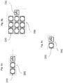
- the means for evaluating the detected optical signals have means for pattern recognition which are able, for example, between, for example in Figure 6a ) -c) different types of light sources or luminaires shown.
- the means for image processing can be means for contrast or difference image analysis, so that, for example, the signal from a light source 220 or lamp 200 previously activated for signal output is used for a further repetition of the method before the detection of optical signals in the case of the next repetition of the method Light source 220 or lamp 200 does not have to be switched off.
- other or further means for detecting an optical signal 300 can be provided.
- these can be brightness sensors or color sensors.
- the position of the light sources 220 or lights 200 is described by the position and arrangement of the sensor.
- the evaluation then preferably also consists in the reproduction of this position and arrangement.
- one or more sensors of this type which can have a directional detection area, for example, it is possible, by using the method according to the invention, to find a reflection in the operating address for certain brightness gradients in a room.
- all light sources or lights that cause the detection of a characteristic brightness value at a specific sensor and thus have a characteristic position could be provided with an identical operating address.
- the means for acquiring an optical signal 300 are designed to separate spectral components of a acquired signal from one another. This can also take place particularly advantageously subsequently with means for evaluating the information generated by the means for detecting optical signals. This can be used to provide different types of light sources, for example in a media system with company addresses from different address ranges. This further development thus creates the possibility of achieving improved automation of the company address assignment in a media system, for example by separating the company address space for red, green or blue light sources.
- the operating address is determined by segment information 351a, 352a, the segment information being determined by a detection area 351, 352 of one of the means for detecting optical signals.
- the position information consists of a characteristic assignment of the light source 220 or lamp 200 to a specific segment, so that the segment information becomes part of the position information.
- the operating address which is assigned to a position of a light source 220 or lamp 200 is determined by comparing the position with information from a reference data source 110 assigned to this position.
- the reference data source preferably provides a schematic image of the lighting or media system in such a way that the number and type of light sources or lights is determined at least in partial sections.
- the reference data source preferably also provides information on the original addresses of lights 200 or light sources 220 of the lighting or media system.
- the company addresses are preferably assigned fully automatically with the aid of the reference data source.
- all light sources 220 or lights 200 are contacted by the control unit 100 and caused to emit an optical signal before the method described above is carried out.
- This is used to acquire comprehensive reference information which, with the aid of the means for acquiring optical signals 300, is supplemented by the position and number of light sources 220 or lights 200 and accordingly represents an image of the components of the lighting or media system.
- means for pattern recognition are provided as means for evaluation, which assign the detected position of the lights to an operating address range that is characteristic of the recognized pattern.
- the combination of the design variants of the method according to the invention also allows the method to be easily adapted to different lighting and media systems.
- the combination of a segmented company address assignment as described above with an assignment supported by information from a reference data source or in connection with pattern recognition is particularly advantageous.
- the illustrated lighting or media system can be implemented with a large number of different lights 200 or light sources 220.
- it can be a linear light - e.g. also in Figure 6a shown - a surface light ( Figure 6b ), a single lamp ( Figure 6c ) or a free luminaire arrangement.
- the configuration as a light source or LED chain or a display element formed from a plurality of light sources 220, for example in a stadium, is also conceivable.
- This multiplicity of different light sources 220 or lamps 200 is connected directly or indirectly to the control unit 100.
- the means for detecting optical signals 300 are in the embodiment of FIG Figure 3 trained as cameras.
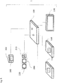
- the addressing system 1 in the exemplary embodiment from FIG Figure 3 or 5 a reference data source 110, which is designed to transmit reference information associated with the position of a lamp 200 or light source 220, in particular the operating address of the light source 220 or lamp 200, to the control unit 100.
- a reference data source 110 which is designed to transmit reference information associated with the position of a lamp 200 or light source 220, in particular the operating address of the light source 220 or lamp 200, to the control unit 100.
- the position determined relative to the detection area of the camera can be compared with a lighting or media system image made available by the reference data source 110. And so an operating address for the contacted luminaire can be determined and assigned in a particularly simple manner.
- an optional user interface 120 is provided. This can be used to make additional corrections when assigning the company addresses. For example, inadequate evaluation or detection of the optical signals from light sources 220 or luminaires 200 could mean that manual intervention in address allocation is required.
- the addressing system 1 can have a visualization element 130 such as, for example, in Figure 5 have shown, which is preferably designed to display the operating parameters or, for example, to display the detected optical signals.
- control unit 100 for assigning operating addresses can be integrated into a system controller 140 of the lighting system, which is used to control the operating sequence of the lighting system.
- a system controller 140 of the lighting system which is used to control the operating sequence of the lighting system.
- the reference data source 110 the user interface 120, and the visualization element 130.
- the control unit 100 of the addressing system 1 is located in an independent housing. The switchover between operation of the lighting or media system with the aid of a system controller 140 and assignment of operating addresses by the control unit 100 can then take place, for example, by a switchover unit 150.
- a simple plugging of the associated communication line from the system controller 140 to the control unit 100 is also conceivable.
- the addressing system 1 is suitably multiplexer, Has demultiplexer and splitter 250.
- the main aim is to standardize the communication path and to reduce the installation effort of the lighting system.
- a lighting system could have light sources 220 or lights 200, which are designed for communication with the aid of WLAN, Artnet, DMX or RDM, so that a not inconsiderable effort results in ensuring communication via a large number of different interface types.
- Usually only a few preferred interfaces of different types are therefore integrated into the control unit 100.
- the use of splitters and multiplexers 250 is then particularly useful to expand the communication capability of the control unit 100.
- a method and an addressing system 1 for assigning operating addresses is made available which enables operating addresses to be assigned automatically in a simple manner.
- the invention requires a simple, fast and flexible allocation of business addresses for a large number of light sources or luminaires, so that a significant improvement is achieved.
Landscapes
- Engineering & Computer Science (AREA)
- Computer Networks & Wireless Communication (AREA)
- Signal Processing (AREA)
- Circuit Arrangement For Electric Light Sources In General (AREA)
Description
Die vorliegende Erfindung betrifft ein Verfahren sowie ein System zur Vergabe von Betriebsadressen für Lichtquellen oder Leuchten, welche Bestandteil eines Beleuchtungs- oder Mediensystems sind.The present invention relates to a method and a system for assigning operating addresses for light sources or luminaires which are part of a lighting or media system.
Moderne und komplexe Gebäude verfügen über umfangreiche Mittel zur Steuerung und Kontrolle der Einrichtungen des Gebäudes. Einerseits bedingt dies einen erhöhten Komfort für die Bewohner oder Benutzer, wenn möglichst viele zu koordinierenden Betriebsfunktionen durch Regelungseinrichtungen unterstützt gesteuert werden, andererseits betrifft die Ausgestaltung der Haustechnik auch die Gebäude- und Betriebssicherheit, sowie Energie- und Kosteneffizienz. Speziell in komplexen Gebäuden, wie z.B. Krankenhäusern, Flughäfen oder auch anderen öffentlichen Gebäuden sind umfangreich regelbare Beleuchtungseinrichtungen vorgesehen. Besonderes dann, wenn variabel zu nutzende Medien- oder Leitsysteme hinzukommen ist die Frage nach flexibel und kosteneffizient veränderbaren Systemen unumgänglich.Modern and complex buildings have extensive means of managing and monitoring the facilities of the building. On the one hand, this results in increased comfort for the residents or users if as many operational functions to be coordinated as possible are controlled with the support of control devices; Extensively controllable lighting systems are provided especially in complex buildings such as hospitals, airports or other public buildings. Particularly when media or control systems that can be used variably are added, the question of flexibly and cost-effectively changeable systems is inevitable.
Daher hat sich für komplexe Beleuchtungsanlagen oder Mediensysteme die Verwendung von zentralen Steuereinheiten zur Steuerung und Regelung etabliert, mit deren Hilfe der Verdrahtungsaufwand reduziert sowie eine flexible Nutzung und Erweiterung der Systeme gegeben ist. Üblicherweise verfügt eine derartige zentrale Steuereinheit über den Anschluss zu einem Bussystem, welches die Fernsteuerung und Regelung einer Lichtquelle oder Leuchte in einem System der beschriebenen Art ermöglicht.Therefore, the use of central control units for control and regulation has become established for complex lighting systems or media systems, with the help of which the wiring effort is reduced and the systems can be used and expanded flexibly. Such a central control unit usually has a connection to a bus system which enables the remote control and regulation of a light source or lamp in a system of the type described.
Zur Kommunikation mit einer Lichtquelle dient in der Regel eine, jeder separat steuerbaren Lichtquelle zugeordnete, individuelle Ursprungsadresse, welche ausreichende Komplexität aufweist um eine Eindeutigkeit zu gewährleisten. Zur Vereinfachung der Kommunikation und Verbesserung der Steuerungs- und Regelungsmöglichkeiten der Beleuchtungsanlage ist üblicherweise vorgesehen, jeder dieser separat steuerbaren Lichtquellen eine spezifische Betriebsadresse mit geringer Komplexität zuzuweisen. Dadurch vereinfacht sich die Kommunikation immens und es entstehen neue Kommunikationsmöglichkeiten und Steuerungsfunktionen, zum Beispiel durch die Adressierung einer Gruppe von Lichtquellen mit Hilfe einer dieser Gruppe zugeordneten Betriebsadresse.An individual original address assigned to each separately controllable light source, which is sufficiently complex to ensure uniqueness, is generally used for communication with a light source. To simplify communication and improve the control and regulation options of the lighting system, provision is usually made for each of these separately controllable light sources to be assigned a specific, low-complexity operating address. This simplifies communication immensely and creates new communication options and control functions, for example by addressing a group of light sources with the help of an operating address assigned to this group.
Die Festlegung der Betriebsadressen erfolgt dabei üblicherweise vor oder bei der Installation der Beleuchtungsanlage. Ein gebräuchliches Verfahren zur Vergabe von Betriebsadressen sieht vor eine einzelne Lichtquelle der Beleuchtungsanlage zu einer Signalabgabe zu veranlassen. Anschließend muss durch das Installationspersonal festgestellt werden, welche Lichtquelle das Signal abgegeben hat. Daraufhin wird dieser Lichtquelle eine dem Beleuchtungsanlagenkonzept entsprechende Betriebsadresse zugewiesen. Dies wird solange wiederholt, bis jede separat steuerbare Lichtquelle der Beleuchtungsanlage eine geeignete Betriebsadresse erhalten hat.The establishment addresses are usually established before or during the installation of the lighting system. A common method for assigning company addresses provides for a single light source of the lighting system to be caused to emit a signal. The installation staff must then determine which light source emitted the signal. This light source is then assigned an operating address that corresponds to the lighting system concept. This is repeated until each separately controllable light source of the lighting system has received a suitable operating address.
Bei einer hohen Anzahl von Lichtquellen - beispielsweise bei einem LED-Mediensystem mit 500x500 Lichtquellen - erweist sich dieses Verfahren jedoch, durch die häufige Wiederholung manueller Arbeitsschritte als ungeeignet.With a high number of light sources - for example with an LED media system with 500x500 light sources - this method proves to be unsuitable due to the frequent repetition of manual work steps.
Aus der
Aus der
Aus der
Aus der
Aufgabe der vorliegenden Erfindung ist es ein Verfahren zur Vergabe von Betriebsadressen zu verbessen und zu vereinfachen.The object of the present invention is to improve and simplify a method for assigning company addresses.
Diese Aufgabe wird durch ein Verfahren mit den Merkmalen des Anspruch 1 gelöst. Vorteilhafte Weiterbildungen sind Gegenstand der abhängigen Ansprüche.This object is achieved by a method with the features of
Das erfindungsgemäße Verfahren zur Vergabe von Betriebsadressen für Lichtquellen oder Leuchten, welche Bestandteil eines Beleuchtungs- oder Mediensystems sind sieht vor, dass eine Steuereinheit eine Lichtquelle oder Leuchte unter Verwendung einer der Lichtquelle bzw. Leuchte zugeordneten Ursprungsadresse kontaktiert. Ferner veranlasst die Steuereinheit die Lichtquelle oder Leuchte, sich durch Abgabe eines optischen Signals zu identifizieren. Nachfolgend wird die Position der sich identifizierenden Lichtquelle bzw. Leuchte erfasst. Dies erfolgt mit Hilfe von Mitteln zur Erfassung optischer Signale, welche eine Information oder Signal erzeugen und ferner mit Hilfe von Mitteln zur Auswertung dieser Information oder dieses Signals. Auf Basis der so erfassten Position und entsprechend einem Referenzschema des Beleuchtungs- oder Mediensystems, welches eine Zuordnung einer Betriebsadresse zu einer Lichtquellenposition bzw. Leuchtenposition enthält, weist die Steuereinheit der Lichtquelle bzw. Leuchte nun eine Betriebsadresse zu. Die Schritte - Kontaktieren, Identifizieren, Position Erfassen sowie Betriebsadresse Zuweisen - können nun für jede Lichtquelle oder Leuchte erfolgen, die dazu vorgesehen ist eine Betriebsadresse zu erhalten. Die Mittel zur Erfassung optischer Signale weisen eine Kamera auf und die Mittel zur Auswertung des erfassten optischen Signals sind Mittel zur Bildverarbeitung. Die Mittel zur Auswertung der erfassten optischen Signale weisen Mittel zur Mustererkennung auf. Des Weiteren weist das Verfahren vor Ausführung der obigen Schritte zusätzlich folgende Schritte auf: die Steuereinheit kontaktiert alle Lichtquellen bzw. Leuchten und veranlasst diese ein optisches Signal abzugeben; mit Hilfe der Mittel zur Erfassung optischer Signale wird eine Referenzinformation erzeugt, welche die volle Signalinformation des Beleuchtungs- oder Mediensystems umfasst; aus der vollen Signalinformation wird mit Hilfe der Mittel zur Auswertung der erfassten optischen Signale die Anzahl und Position der Lichtquellen bzw. Leuchten ermittelt; anhand der Referenzinformation wird das Referenzschema des Beleuchtungs- oder Mediensystems erstellt, welches die Zuordnung einer Betriebsadresse zu einer Lichtquellenposition bzw. Leuchtenposition enthält.The method according to the invention for assigning operating addresses for light sources or luminaires which are part of a lighting or media system provides that a control unit contacts a light source or luminaire using an original address assigned to the light source or luminaire. Furthermore, the control unit causes the light source or lamp to identify itself by emitting an optical signal. The position of the identifying light source or lamp is then recorded. This takes place with the aid of means for detecting optical signals, which generate information or a signal, and further with the aid of means for evaluating this information or this signal. On the basis of the position thus detected and in accordance with a reference scheme of the lighting or media system, which contains an assignment of an operating address to a light source position or lamp position, the control unit now assigns an operating address to the light source or lamp. The steps - contacting, identifying, recording the position and assigning the operating address - can now be carried out for each light source or lamp that is intended to receive an operating address. The means for capturing optical signals have a camera and the means for evaluating the captured optical signal are means for image processing. The means for evaluating the detected optical signals have means for pattern recognition. Furthermore, before performing the above steps, the method additionally has the following steps: the control unit contacts all light sources or lights and causes them to emit an optical signal; with the aid of the means for detecting optical signals, reference information is generated which includes the full signal information of the lighting or media system; The number and position of the light sources or lamps is determined from the full signal information with the aid of the means for evaluating the detected optical signals; Using the reference information, the reference scheme of the lighting or media system is created, which contains the assignment of an operating address to a light source position or luminaire position.
Erfindungsgemäß, wird ferner ein Adressierungssystem vorgeschlagen, welches eine Steuereinheit aufweist, welche dazu ausgebildet ist, die Lichtquellen bzw. Leuchten unter Verwendung von den Lichtquellen bzw. Leuchten zugeordneten Ursprungsadressen einzeln zu kontaktieren und zu veranlassen, sich durch die Abgabe eines optischen Signals zu identifizieren. Ferner weist das Adressierungssystem Mittel zur Erfassung optischer Signale der sich identifizierenden Lichtquelle oder Leuchte sowie Mittel zur Auswertung der erfassten optischen Signale auf, welche dazu ausgebildet sind durch eine Bewertung des erfassten optischen Signals die Position einer sich identifizierenden Lichtquelle oder Leuchte zu bestimmen. Weiterhin ist die Steuereinheit dazu ausgebildet, auf Basis der durch die Mittel zur Auswertung optischer Signale bestimmten Position der Lichtquelle oder Leuchte und entsprechend einem Referenzschema des Beleuchtungs- oder Mediensystems, welches eine Zuordnung einer Betriebsadresse zu einer Lichtquellenposition bzw. Leuchtenposition enthält, eine Betriebsadresse zuzuweisen. Die Mittel zur Erfassung eines optischen Signals weisen eine Kamera auf und die Mittel zur Auswertung des erfassten optischen Signals sind Mittel zur Bildverarbeitung. Die Mittel zur Auswertung der erfassten optischen Signale weisen Mittel zur Mustererkennung auf. Bevor die Steuereinheit die Lichtquellen bzw. Leuchten einzeln kontaktiert, ist die Steuereinheit weiterhin dazu ausgebildet, alle Lichtquellen bzw. Leuchten zu kontaktieren und zu veranlassen ein optisches Signal abzugeben; die Mittel zur Erfassung optischer Signale sind weiterhin dazu ausgebildet, eine Referenzinformation zu erzeugen, welche die volle Signalinformation des Beleuchtungs- oder Mediensystems umfasst; die Mittel zur Auswertung der erfassten optischen Signale sind weiterhin dazu ausgebildet, aus der vollen Signalinformation die Anzahl und Position der Lichtquellen bzw. Leuchten zu ermitteln; und die Mittel zur Auswertung der erfassten optischen Signale sind weiterhin dazu ausgebildet, anhand der Referenzinformation das Referenzschema des Beleuchtungs- oder Mediensystems zu erstellen, welches die Zuordnung einer Betriebsadresse zu einer Lichtquellenposition bzw. Leuchtenposition enthält.According to the invention, an addressing system is also proposed which has a control unit which is designed to individually contact the light sources or lamps using original addresses assigned to the light sources or lamps and to cause them to identify themselves by emitting an optical signal. Furthermore, the addressing system has means for capturing optical signals from the identifying light source or lamp as well as means for evaluating the captured optical signals, which are designed to determine the position of an identifying light source or lamp by evaluating the captured optical signal. Furthermore, the control unit is designed to assign an operating address based on the position of the light source or lamp determined by the means for evaluating optical signals and according to a reference scheme of the lighting or media system, which contains an assignment of an operating address to a light source position or lamp position. The means for acquiring an optical signal have a camera and the means for evaluating the acquired optical signal are means for image processing. The means for evaluating the detected optical signals have means for pattern recognition. Before the control unit contacts the light sources or lights individually, the control unit is also designed to contact all light sources or lights and to cause them to emit an optical signal; the means for acquiring optical signals are also designed to generate reference information which includes the full signal information of the lighting or media system; the means for evaluating the detected optical signals are also designed to determine the number and position of the light sources or lights from the full signal information; and the means for evaluating the detected optical signals are also designed to use the reference information to create the reference scheme of the lighting or media system, which contains the assignment of an operating address to a light source position or lamp position.
Nachfolgend soll die Erfindung anhand der beiliegenden Zeichnung näher erläutert werden, wobei gleiche Elemente in allen Darstellungen mit den gleichen Bezugszeichen versehen sind. Es zeigen
Figur 1- ein erstes Ausführungsbeispiel eines erfindungsgemäßen Adressierungssystems;
- Figur 2
- den schematischen Ablauf eines erfindungsgemäßen Verfahrens zur Vergabe einer Betriebsadresse;
- Figur 3
- ein weiteres Ausführungsbeispiel eines erfindungsgemäßen Adressierungssystems;
- Figur 4
- ein Beispiel einer möglichen Segmentierung des Betriebsadressenbereichs;
- Figur 5
- ein weiteres Ausführungsbeispiel eines erfindungsgemäßen Adressierungssystems; und
- Figur 6
- Beispiele für zu unterscheidende Leuchtenformen.
- Figure 1
- a first embodiment of an addressing system according to the invention;
- Figure 2
- the schematic sequence of a method according to the invention for assigning an operating address;
- Figure 3
- a further embodiment of an addressing system according to the invention;
- Figure 4
- an example of a possible segmentation of the operating address range;
- Figure 5
- a further embodiment of an addressing system according to the invention; and
- Figure 6
- Examples of different luminaire shapes.
An einer Wand montiert könnte das Mediensystem beispielsweise zur Anzeige von Werbung gedacht sein. Zur schnellen und flexiblen Darstellung der Werbebotschaft ist es sinnvoll, jeder dieser Vielzahl von LEDs 220 zur Kommunikation mit der Systemsteuerung - insbesondere zur Verbesserung der individuellen Ansteuerbarkeit - eine Betriebsadresse zuzuweisen, wobei diese Betriebsadresse insbesondere die Position der zugehörigen LED 220 in der Anordnung berücksichtigt.Mounted on a wall, the media system could be intended to display advertising, for example. In order to display the advertising message quickly and flexibly, it makes sense to assign an operating address to each of these multitudes of
Eine manuelle Vergabe der Betriebsadressen ist bei dieser Vielzahl von Lichtquellen 220 bzw. Leuchten 200 sehr zeitaufwändig und ineffektiv. Mit Hilfe eines erfindungsgemäßen Adressierungssystems 1 kann dies jedoch immens erleichtert und automatisiert werden.A manual assignment of the operating addresses is very time-consuming and ineffective with this large number of
Erfindungsgemäß ist im Ausführungsbeispiel von
Ferner weist das Adressierungssystem 1 Mittel zur Erfassung optischer Signale 300 des Mediensystems auf. Im Ausführungsbeispiel handelt es sich dabei um eine Kamera 300, welche vorzugsweise dazu ausgebildet ist ein optisches Signal in ein elektrisches Signal oder eine Folge von elektrischen Signalen zu konvertieren, vorzugsweise zu digitalisieren. Weiterhin weist das Adressierungssystem 1 Mittel zur Auswertung der erfassten optischen Signale auf, welche dazu ausgebildet sind durch eine Bewertung des erfassten optischen Signals die Position einer sich identifizierenden LED-Lichtquelle 220 zu bestimmen. Dies ist bei einer Abbildung der LED-Leuchtquellen 220 durch eine Kamera 300 in besonders einfacher Weise möglich, da die geometrische Position unmittelbar aus der Position der kontaktierten LED in der Abbildung bestimmt werden kann, und besonders vorteilhafte Algorithmen zur Positionsbestimmung wie z.B. Methoden der Bildverarbeitung verwendet werden können.The addressing
Weiterhin ist die Steuereinheit 100 dazu ausgebildet, auf Basis der durch die Mittel zur Auswertung der erfassten optischen Signale bestimmten Position der LEDs eine Betriebsadresse zuzuweisen. Im Ausführungsbeispiel erfolgt die Ansteuerung der LEDs über ein Kontrollelement 210 des Mediensystems, welches dazu ausgebildet ist, jede LED einzeln zu steuern und eine Ursprungsadresse für jede einzeln ansteuerbare LED wiederzugeben, sowie eine Betriebsadresse für jede LED-Lichtquelle des Mediensystems 240 zu empfangen. Vorzugsweise bildet sich die geometrische Position der LEDs in der zugewiesenen Betriebsadresse ab, beispielsweise kann die Betriebsadresse dann auch eine Koordinateninformation, welche einer Position einer LED in einer Zeile bzw. Spalte des Mediensystems 240 entspricht, enthalten. Dies stellt eine Möglichkeit dar, auf besonders einfache Art und Weise eine Betriebsadresse geeignet festzulegen.Furthermore, the
Neben der Vergabe von Betriebsadressen für ein Mediensystem ist darüber hinaus die Anwendung für eine Vielzahl von Beleuchtungs- und/oder Mediensysteme denkbar. Beispielsweise könnte es sich um eine in eine Wand oder Fassade eines Hauses bzw. Gebäudes integrierte Beleuchtungsanlage mit einer Vielzahl von Lichtquellen oder Leuchten dargestellt handeln. Diese können zur Informationsdarstellung wie im Falle des im Ausführungsbeispiel von
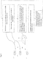
In
Zunächst kontaktiert eine Steuerungseinheit 100 eine Lichtquelle 220 bzw. Leuchte. Die Kontaktierung erfolgt dabei mit Hilfe einer der Lichtquelle 220 bzw. Leuchte 200 zugeordneten Ursprungsadresse, welche der Steuerungseinheit 100 vor Beginn des erfindungsgemäßen Verfahrens bekannt ist. Beispielsweise könnte die Steuerungseinheit 100 zuvor mittels bidirektionaler Kommunikation mit Kontrollelementen 210, zuerst eine Anfrage an alle Lichtquellen 220 bzw. Leuchten 200 richten ihre Ursprungsadressen mitzuteilen und die erhaltene Information anschließend speichern.First, a
Diese Ursprungsadresse kann einerseits eine gerätespezifische vom Hersteller der Lichtquelle 220 oder Leuchte 200 bei der Produktion eindeutig kodierte Adresse sein. Darüber hinaus ist aber auch denkbar eine Ursprungsadresse - z.B. ähnlich dem DALI Standard - zufällig erzeugen zu lassen. In beiden Fällen ist diese Ursprungsadresse der Steuereinheit 100 vor Beginn des erfindungsgemäßen Verfahrens zur Vergabe einer Betriebsadresse bekannt.On the one hand, this original address can be a device-specific address that is uniquely coded by the manufacturer of the
Durch die Steuereinheit 100 wird die Lichtquelle 220 bzw. Leuchte 200 kontaktiert und veranlasst ein optisches Signal abzugeben. Beispielsweise kann die Signalabgabe der Lichtquelle 220 oder Leuchte 200 darin bestehen, dass ein Ein- oder Ausschalten bzw. Dimmen der Lichtquelle 220 oder Leuchte 200 erfolgt. Die Signalabgabe ist dabei vorzugsweise an die Steuerungs- und Regelungsmöglichkeiten einer Kontrolleinheit 210, welche den Betriebszustand einer Lichtquelle 220 Leuchte 200 steuert und regelt angepasst.The
Ferner wird mit Hilfe von Mitteln zur Erfassung optischer Signale 300 sowie mit Hilfe von Mitteln zur Auswertung der erfassten optischen Signale die Position der sich identifizierenden Lichtquelle 220 bzw. Leuchte 200 erfasst.Furthermore, the position of the identifying
Bei der erfassten Position handelt es sich vorzugsweise um die geometrische Lage einer Lichtquelle 220 oder Leuchte 200 relativ zu einem Ursprungspunkt. Dabei kann es vorteilhaft sein, mehrere Ursprungspunkte, welche sich beispielsweise durch Lage in verschiedenen Räumen oder Gebäudeteilen oder auch Leuchten bzw. Mediensystemen auszeichnen, vorzusehen. Insbesondere sind verschiedene Ausgestaltungsvarianten der Positionsinformation denkbar, welche - wie im weiteren erläutert - vornehmlich durch die Mittel zu Erfassung eines optischen Signals oder deren Zusammenwirken bedingt sind.The detected position is preferably the geometric position of a
Weiterhin wird auf Basis der ermittelten Position dann durch die Steuereinheit 100 eine Betriebsadresse der zur Signalabgabe veranlassten Lichtquelle 220 oder Leuchte 200 zugewiesen.Furthermore, on the basis of the determined position, the
Die Schritte - Kontaktierung, Veranlassen einer optischen Signalabgabe, Erfassen eines optischen Signals, Auswertung des erfassten Signals, Ermitteln der Position, sowie Zuweisung einer Betriebsadresse auf Basis der Position - können nun nacheinander für andere Lichtquellen 220 oder Leuchten 200, wiederholt werden, solange, bis jede zum Empfang einer Betriebsadresse vorgesehene Lichtquelle 220 oder Leuchte 200 eine geeignete Betriebsadresse aufweist.The steps - contacting, initiating an optical signal output, acquiring an optical signal, evaluating the acquired signal, determining the position, as well as assigning an operating address based on the position - can now be repeated one after the other for other
Beispielsweise könnte ferner vorgesehen sein, dass die Kommunikation der Steuereinheit 100 mit den Mitteln zur Erfassung optischer Signale 300 über das Kommunikationsnetz des Beleuchtungs- oder Mediensystems erfolgt.For example, it could also be provided that the communication of the
In dem in
Gemäß der Erfindung weisen die Mittel zur Erfassung optischer Signale 300 eine Kamera auf. Erfindungsgemäß ist dabei vorgesehen, dass die Mittel zur Auswertung der erfassten optischen Signale Mittel zur Bildverarbeitung sind. Die Mittel zur Auswertung der erfassten optischen Signale weisen Mittel der Mustererkennung auf, die beispielsweise in der Lage sind, zwischen, exemplarisch in
In einer Weiterbildung des Erfindungsgedankens können andere oder weitere Mittel zur Erfassung eines optischen Signals 300 vorgesehen sein. Beispielsweise kann es sich dabei um Helligkeitssensoren oder Farbsensoren handeln. Die Position der Lichtquellen 220 oder Leuchten 200 wird dabei durch die Lage und Anordnung des Sensors beschrieben. Die Auswertung besteht dann vorzugsweise auch in der Wiedergabe dieser Lage und Anordnung. Mit einem oder mehreren Sensoren dieser Art, welche beispielsweise einen gerichteten Erfassungsbereich aufweisen können, besteht die Möglichkeit, durch Anwendung des erfindungsgemäßen Verfahrens eine Wiederspiegelung in der Betriebsadresse für bestimmte Helligkeitsverläufe in einem Raum zu finden. Beispielsweise könnten alle Lichtquellen oder Leuchten, welche die Erfassung eines charakteristischen Helligkeitswerts an einem bestimmten Sensor hervorrufen und somit eine charakteristische Position haben, mit identischer Betriebsadresse versehen sein.In a further development of the inventive concept, other or further means for detecting an
Desweiteren ist denkbar, dass die Mittel zur Erfassung eines optischen Signals 300 dazu ausgebildet sind spektrale Anteile eines erfassten Signals von einander zu separieren. Besonders vorteilhaft kann dies auch nachfolgend mit Mitteln zur Auswertung der von den Mitteln zur Erfassung optischer Signale erzeugten Information erfolgen. Dies kann dazu dienen verschiedene Arten von Lichtquellen, beispielsweise in einer Medienanlage mit Betriebsadressen aus unterschiedlichen Adressbereichen zu versehen. Somit ist durch diese Weiterbildung die Möglichkeit geschaffen, beispielsweise in einem Mediensystem eine verbesserte Automatisierung der Betriebsadressvergabe zu erreichen, beispielsweise durch Separation des Betriebsadressraumes für rote, grüne oder blaue Lichtquellen.Furthermore, it is conceivable that the means for acquiring an
In
Ferner kann vorgesehen sein, dass die Betriebsadresse, welche einer Position einer Lichtquelle 220 oder Leuchte 200 zugeordnet ist durch Vergleich der Position mit einer dieser Position zugordneten Information einer Referenzdatenquelle 110 festgelegt wird. Vorzugsweise stellt die Referenzdatenquelle ein schematisches Abbild der Beleuchtungs- oder Medienanlage in der Art zur Verfügung, dass die Anzahl und Art der Lichtquellen bzw. Leuchten zumindest in Teilabschnitten bestimmt ist. Darüber hinaus ist beispielsweise vorgesehen in einer der Auswertung der erfassten optischen Signale angepassten Art und Weise die Positionsinformation einer Betriebsadresse zuzuordnen. Insbesondere ist eine Konsistenz der Metrik notwendig. Darüber hinaus stellt die Referenzdatenquelle vorzugsweise auch Informationen zu Ursprungsadressen von Leuchten 200 oder Lichtquellen 220 des Beleuchtungs- oder Mediensystems zur Verfügung. Und fernerhin erfolgt vorzugsweise die Vergabe der Betriebsadressen mit Hilfe der Referenzdatenquelle vollautomatisch.Furthermore, it can be provided that the operating address which is assigned to a position of a
Ferner ist bei dem erfindungsgemäßen Verfahren vorgesehen, dass zunächst vor Ausführung des vorbeschriebenen Verfahrens alle Lichtquellen 220 oder Leuchten 200 von der Steuereinheit 100 kontaktiert werden und veranlasst werden, ein optisches Signal abzugeben. Dies dient zur Erfassung einer umfassenden Referenzinformation, welche mit Hilfe der Mittel zur Erfassung optischer Signale 300 um die Position und Anzahl der Lichtquellen 220 bzw. Leuchten 200 ergänzt ist und dementsprechend ein Abbild der Komponenten des Beleuchtungs-oder Mediensystems darstellt. Hierbei sind Mittel zur Mustererkennung als Mittel zur Auswertung vorgesehen, welche die erfasste Position der Leuchten einem für die erkannten Muster charakteristischen Betriebsadressenbereich zuordnen.Furthermore, it is provided in the method according to the invention that all
Hervorzuheben ist, dass auch durch die Kombination der Ausgestaltungsvarianten des erfindungsgemäßen Verfahrens sich eine einfache Anpassung des Verfahrens an unterschiedliche Beleuchtungs- und Medienanlagen realisieren lässt. So ist beispielsweise die Kombination einer wie oben beschriebenen segmentierten Betriebsadressvergabe mit einer Vergabe unterstützt durch Informationen aus einer Referenzdatenquelle oder in Verbindung mit einer Mustererkennung besonders vorteilhaft.It should be emphasized that the combination of the design variants of the method according to the invention also allows the method to be easily adapted to different lighting and media systems. For example, the combination of a segmented company address assignment as described above with an assignment supported by information from a reference data source or in connection with pattern recognition is particularly advantageous.
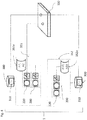
Das in
Diese Vielzahl von unterschiedlichen Lichtquellen 220 oder Leuchten 200 ist an die Steuereinheit 100 direkt oder indirekt angeschlossen.This multiplicity of different
Desweiteren sind die Mittel zur Erfassung optischer Signale 300 im Ausführungsbeispiel von
Ferner weist das Adressierungssystem 1 im Ausführungsbeispiel von
So kann nun gemäß dem Ausführungsbeispiel von
Desweiteren ist im Ausführungsbeispiel von
In einer Weiterbildung kann jedoch auch vorgesehen sein, dass über die Benutzerschnittstelle 120 grundlegende Vorkonfigurationen zur Betriebsadressvergabe durchgeführt werden. Die kann beispielsweise die Festlegung eines zugewiesenen Betriebsadressraumes betreffen, sowie die Auswahl eines geeigneten Algorithmus, beispielsweise könnte zwischen Mustererkennung, Segmentierung und Referenzdatenquelle 110 umgeschaltet werden. Ebenso könnte die Auswahl verschiedener Mittel zur Erfassung eines optischen Signals mit Hilfe der Benutzerschnittstelle 120 durchgeführt werden.In a further development, however, it can also be provided that basic preconfigurations for the assignment of company addresses are carried out via the
Beispielsweise ist es weiterhin möglich, dass die Zuordnung einer relativ zum Erfassungsbereich der Kamera ermittelten Position vorbestimmten Werten der Referenzdatenquelle 110 nicht eindeutig zugeordnet werden kann. So kann durch manuelle Korrektur diese mangelnde Eindeutigkeit aufgelöst werden, und gleichzeitig führt dies bei wiederholter Anwendung eines erfindungsgemäßen Verfahrens zur Vergabe von Betriebsadressen dazu, dass mit Hilfe des Ausschlussprinzips eine größere Genauigkeit in der Zuordnung der weiteren Lichtquellen 220 oder Leuchten 200 zu Informationen der Referenzdatenquelle 110 gegeben ist.For example, it is also possible that the assignment of a position determined relative to the detection area of the camera cannot be clearly assigned to predetermined values of the
Ergänzend kann das Adressierungssystem 1 ein Visualisierungselement 130 wie beispielsweise in
Einerseits kann die Steuereinheit 100 zur Vergabe von Betriebsadressen in eine Systemsteuerung 140 des Beleuchtungssystems, welche zur Steuerung des Betriebsablaufs des Beleuchtungssystems dient, integriert sein. Dies ist ebenso für die Referenzdatenquelle 110, die Benutzerschnittstelle 120, und das Visualisicrungselement 130 denkbar. Es kann jedoch auch vorgesehen sein, dass sich die Steuereinheit 100 des Adressierungssystems 1 in einem selbständigen Gehäuse befindet. Die Umschaltung zwischen einem Betrieb des Beleuchtungs- oder Mediensystems mit Hilfe einer Systemsteuerung 140 und einer Vergabe von Betriebsadressen durch die Steuereinheit 100 kann dann beispielsweise durch eine Umschalteinheit 150 erfolgen. Jedoch ist auch ein einfaches Umstecken der zugehörigen Kommunikationsleitung von der Systemsteuerung 140 zur Steuereinheit 100 denkbar.On the one hand, the
Vorzugsweise ist vorgesehen, dass nur wenige Kommunikationswege zu berücksichtigen sind. Insbesondere verringert sich bei wenigen vorzugsweise einheitlichen Kommunikationswegen der konstruktive Aufwand für die Steuereinheit 100 erheblich. Deshalb ist in einer Weiterbildung der Erfindung vorgesehen, dass das Adressierungssystem 1 in geeigneter Weise Multiplexer, Demultiplexer sowie Splitter 250 aufweist. Vornehmlich wird dabei eine Vereinheitlichung des Kommunikationsweges sowie eine Reduzierung des Installationsaufwandes der Beleuchtungsanlage angestrebt. Beispielsweise könnte ein Beleuchtungssystem Lichtquellen 220 oder Leuchten 200 aufweisen, welche zur Kommunikation mit Hilfe von WLAN, Artnet, DMX oder RDM ausgebildet sind, so dass ein nicht unerheblicher Aufwand resultiert um die Kommunikation uber eine Vielzahl unterschiedlicher Schnittstellentypen sicherzustellen. Üblicherweise sind deshalb nur wenige Vorzugsschnittstellen verschiedenen Typs in die Steuereinheit 100 integriert. Zur Erweiterung der Kommunikationsfähigkeit der Steuereinheit 100 ist dann der Einsatz van Splittern und Multiplexern 250 besonders sinnvoll.It is preferably provided that only a few communication paths need to be taken into account. In particular, if there are a few, preferably uniform, communication paths, the design effort for the
Mit Hilfe der Erfindung wird also ein Verfahren sowie ein Adressierungssystem 1 zur Vergabe von Betriebsadressen zur Verfügung gestellt, welches auf einfache Weise eine automatische Vergabe von Betriebsadressen ermöglicht. Die Erfindung bedingt eine einfache, schnelle und flexible Vergabe vaon Betriebsadressen für eine Vielzahl von Lichtquellen oder Leuchten, so dass eine wesentliche Verbesserung erreicht ist.With the aid of the invention, a method and an addressing
Claims (6)
- Method for allocating operating addresses to light sources or lights which are part of an illumination or media system, wherein the method comprises the following steps:a) a control unit (100) contacts a light source (220) or light (200) by using a source address associated with the light source or light and causes it to identify itself by emitting an optical signal;b) the position of the light source (220) or light (200) identifying itself is detected with the aid of means for detecting optical signals (300) and means for evaluating the detected optical signals;c) the control unit (100) assigns an operating address to the light source (220) or light (200) identifying itself on the basis of the position detected in step b) and according to a reference scheme of the illumination or media system which contains an association of an operating address with a light source position or light position;d) the steps a) to c) are repeated until corresponding operating addresses have been assigned to all light sources (220) or lights (200),wherein the means for detecting optical signals (300) comprise a camera, and the means for evaluating the detected optical signal are means for image processing,
wherein the means for evaluating the detected optical signals comprise means for pattern recognition, and
wherein the method additionally comprises the following steps before execution of steps a)-d):- the control unit (100) contacts all light sources (220) or lights (200) and causes them to emit an optical signal;- with the aid of the means for detecting optical signals (300), reference information is generated which includes the full signal information of the illumination or media system;- the number and position of the light sources (220) or lights (200) is ascertained from the full signal information with the aid of the means for evaluating the detected optical signals;- the reference information is used to create the reference scheme of the illumination or media system which contains the association of an operating address with a light source position or light position. - Method according to Claim 1,
characterized in that
the control unit (100) for connecting the means for detecting optical signals comprises an interface which is separate from the connection of the light sources (220) or lights (200). - Addressing system for allocating operating addresses to light sources or lights which are part of an illumination or media system, comprising:a) a control unit (100) which is designed to individually contact the light sources (220) or lights (200) by using source addresses associated with the light sources (220) or lights (200) and to cause them to identify themselves by emitting an optical signal;b) means for detecting optical signals (300) of the illumination or media system;c) means for evaluating the detected optical signals, which are designed to determine the position of a light source (220) or light (200) identifying itself by evaluating the detected optical signals;wherein the control unit (100) is furthermore designed to assign an operating address on the basis of the position, determined by the means for evaluating the detected optical signals, of the light source (220) or light (200) identifying itself and according to a reference scheme of the illumination or media system which contains an association of an operating address with a light source position or light position,
wherein the means for detecting an optical signal (300) comprise a camera, and the means for evaluating the detected optical signal are means for image processing,
wherein the means for evaluating the detected optical signals comprise means for pattern recognition, and
wherein, before the control unit (100) individually contacts the light sources (220) or lights (200),- the control unit (100) is furthermore designed to contact all light sources (220) or lights (200) and to cause them to emit an optical signal;- the means for detecting optical signals (300) are furthermore designed to generate reference information including the full signal information of the illumination or media system;- the means for evaluating the detected optical signals are furthermore designed to ascertain the number and position of the light sources (220) or lights (200) from the full signal information;- the means for evaluating the detected optical signals are furthermore designed to create, on the basis of the reference information, the reference scheme of the illumination or media system which contains the association of an operating address with a light source position or light position. - Addressing system according to Claim 3,
characterized in that
the control unit (100) for connecting the means for detecting an optical signal comprises an interface which is separate from the connection of the light sources (220) or lights (200). - Addressing system according to one of the preceding Claims 3 to 4,
characterized in that
the addressing system (1) comprises a user interface (120), especially for manually correcting the position information or an operating address. - Addressing system according to one of the preceding Claims 3 to 5,
characterized in that
the addressing system (1) comprises a visualization element (130) which is designed especially to display the operating parameters and to display the detected optical signal.
Applications Claiming Priority (1)
| Application Number | Priority Date | Filing Date | Title |
|---|---|---|---|
| DE102009050733A DE102009050733A1 (en) | 2009-10-26 | 2009-10-26 | Method and system for assigning operating addresses for light sources or luminaires |
Publications (4)
| Publication Number | Publication Date |
|---|---|
| EP2315503A2 EP2315503A2 (en) | 2011-04-27 |
| EP2315503A3 EP2315503A3 (en) | 2014-12-31 |
| EP2315503B1 EP2315503B1 (en) | 2018-05-30 |
| EP2315503B2 true EP2315503B2 (en) | 2021-06-23 |
Family
ID=43640516
Family Applications (1)
| Application Number | Title | Priority Date | Filing Date |
|---|---|---|---|
| EP10188877.4A Active EP2315503B2 (en) | 2009-10-26 | 2010-10-26 | Method and system for allocating operating addresses to light sources or lights |
Country Status (2)
| Country | Link |
|---|---|
| EP (1) | EP2315503B2 (en) |
| DE (1) | DE102009050733A1 (en) |
Families Citing this family (12)
| Publication number | Priority date | Publication date | Assignee | Title |
|---|---|---|---|---|
| DE102012204686B3 (en) * | 2012-03-23 | 2013-05-23 | Siemens Aktiengesellschaft | Method for configuring lighting system in e.g. office building, involves producing live image of room by electronic camera, and performing identification based on live image that is modified by modification operation |
| DE102012218521A1 (en) * | 2012-10-11 | 2014-04-17 | Zumtobel Lighting Gmbh | Control system for distributed loads, in particular for lamp operating devices, as well as methods for commissioning the system |
| DE102012223966A1 (en) | 2012-12-20 | 2014-06-26 | Zumtobel Lighting Gmbh | Method of addressing luminaires, luminaire for lighting and system for illuminating a room |
| DE202013009490U1 (en) * | 2013-10-25 | 2015-01-26 | Zumtobel Lighting Gmbh | Luminaire or lighting arrangement |
| EP2925090A1 (en) | 2014-03-24 | 2015-09-30 | Heliospectra AB | Method for automatic positioning of lamps in a greenhouse environment |
| EP3180964B1 (en) | 2014-08-14 | 2018-02-28 | Philips Lighting Holding B.V. | A commissioning system for a lighting system |
| US10771907B2 (en) * | 2014-12-11 | 2020-09-08 | Harman International Industries, Incorporated | Techniques for analyzing connectivity within an audio transducer array |
| DE102015201434A1 (en) * | 2015-01-28 | 2016-07-28 | Zumtobel Lighting Gmbh | Method of operating devices in a lighting system |
| US9795015B2 (en) | 2015-06-11 | 2017-10-17 | Harman International Industries, Incorporated | Automatic identification and localization of wireless light emitting elements |
| DE102019113121A1 (en) * | 2019-05-17 | 2020-11-19 | Trilux Gmbh & Co. Kg | Detection of the spatial arrangement of components of a lighting system and assignment of a respective operating address |
| DE102019004492A1 (en) * | 2019-06-28 | 2020-12-31 | Dietmar Friedrich Brück | Method for controlling lights provided with at least one detector unit within at least one room and system for carrying out the method |
| DE102022103672A1 (en) | 2022-02-16 | 2023-08-17 | Bayerische Motoren Werke Aktiengesellschaft | System and method for determining an installation position of an actuator in a vehicle |
Citations (4)
| Publication number | Priority date | Publication date | Assignee | Title |
|---|---|---|---|---|
| GB2418482A (en) † | 2004-09-23 | 2006-03-29 | Wayne Howell | Method for locating luminaires using optical feedback |
| DE202007008363U1 (en) † | 2006-06-09 | 2007-08-23 | Steinel Gmbh | Illumination control device, has sensor instrument with detected motion and presence of detection object e.g. person in recording region and electronic evaluation unit is assigned for detection of produced signal for activated lighting unit |
| US7502034B2 (en) † | 2003-11-20 | 2009-03-10 | Phillips Solid-State Lighting Solutions, Inc. | Light system manager |
| JP2009238526A (en) † | 2008-03-26 | 2009-10-15 | Panasonic Electric Works Co Ltd | Illumination system |
Family Cites Families (5)
| Publication number | Priority date | Publication date | Assignee | Title |
|---|---|---|---|---|
| JP4155676B2 (en) * | 1999-07-30 | 2008-09-24 | 松下電工株式会社 | Lighting control system |
| US7359438B2 (en) * | 2002-11-27 | 2008-04-15 | Clifton Labs, Inc. | Optical communications imager |
| WO2004100624A2 (en) * | 2003-05-05 | 2004-11-18 | Color Kinetics, Inc. | Lighting methods and systems |
| EP1989926B1 (en) * | 2006-03-01 | 2020-07-08 | Lancaster University Business Enterprises Limited | Method and apparatus for signal presentation |
| ES2357086T3 (en) * | 2007-07-18 | 2011-04-18 | Koninklijke Philips Electronics N.V. | PROCEDURE TO PROCESS LIGHT IN A STRUCTURE AND LIGHTING SYSTEM. |
-
2009
- 2009-10-26 DE DE102009050733A patent/DE102009050733A1/en not_active Withdrawn
-
2010
- 2010-10-26 EP EP10188877.4A patent/EP2315503B2/en active Active
Patent Citations (4)
| Publication number | Priority date | Publication date | Assignee | Title |
|---|---|---|---|---|
| US7502034B2 (en) † | 2003-11-20 | 2009-03-10 | Phillips Solid-State Lighting Solutions, Inc. | Light system manager |
| GB2418482A (en) † | 2004-09-23 | 2006-03-29 | Wayne Howell | Method for locating luminaires using optical feedback |
| DE202007008363U1 (en) † | 2006-06-09 | 2007-08-23 | Steinel Gmbh | Illumination control device, has sensor instrument with detected motion and presence of detection object e.g. person in recording region and electronic evaluation unit is assigned for detection of produced signal for activated lighting unit |
| JP2009238526A (en) † | 2008-03-26 | 2009-10-15 | Panasonic Electric Works Co Ltd | Illumination system |
Non-Patent Citations (2)
| Title |
|---|
| Deutsche Obersetzung JP 2009-238526 A † |
| PROF. DR. H. BURKHARDT: "Foundations of Picture Recognition and Picture Analysis Pattern Recognition", 2005, pages 1 - 28, Retrieved from the Internet <URL:https://Imb.informatik.uni-freiburg.de/lectures/old_Imb/mustererkennung/Englische_Folien/index.html> † |
Also Published As
| Publication number | Publication date |
|---|---|
| DE102009050733A1 (en) | 2011-04-28 |
| EP2315503B1 (en) | 2018-05-30 |
| EP2315503A3 (en) | 2014-12-31 |
| EP2315503A2 (en) | 2011-04-27 |
Similar Documents
| Publication | Publication Date | Title |
|---|---|---|
| EP2315503B2 (en) | Method and system for allocating operating addresses to light sources or lights | |
| EP1891838B1 (en) | Determination of the bus address of a subscriber in an illuminating bus system | |
| EP2181567B1 (en) | Method for the start-up of a lighting system | |
| DE102005009228A1 (en) | lamp | |
| EP2364574B1 (en) | Address assignment for bus-capable lighting-means operating devices particularly for leds | |
| EP3120670B1 (en) | Central unit of a bus system, bus system and method for locating bus subscribers | |
| EP1624729B1 (en) | Method for installing a lighting system | |
| EP1955578A1 (en) | Control system for several separately arranged consumers, especially lamp operating devices, and start-up method | |
| EP2508046B1 (en) | Optical signal output of operating parameters with an led lighting unit | |
| DE102017112887A1 (en) | Control apparatus and method for assigning an ID number | |
| DE102015010918B4 (en) | Lighting device and light arrangement | |
| DE102018000893A1 (en) | Method for controlling luminaires provided with at least one detector unit within at least one room and system for carrying out the method | |
| EP2779801A2 (en) | Lighting system and method for controlling a lighting system | |
| DE102012210833B4 (en) | Method for configuring a lighting system | |
| AT15432U1 (en) | Building technology bus system for the operation of building technology devices | |
| EP3182800B1 (en) | Operating device for an illumination system | |
| DE102014119520A1 (en) | Method for configuring a lighting system | |
| DE102013106794B4 (en) | lighting installation | |
| DE102012204686B3 (en) | Method for configuring lighting system in e.g. office building, involves producing live image of room by electronic camera, and performing identification based on live image that is modified by modification operation | |
| DE102014221788A1 (en) | Building technology bus system for the operation of building technology devices | |
| AT17116U1 (en) | Localization of components of a lighting system using light scene control | |
| WO2015143470A2 (en) | Illumination system having a control device | |
| WO2021156300A1 (en) | Lighting module, lighting system and operating method | |
| DE102014009798A1 (en) | Method for identifying subscriber nodes | |
| EP3307023A1 (en) | Operating device for light with output of status information in particular for fault analysis |
Legal Events
| Date | Code | Title | Description |
|---|---|---|---|
| PUAI | Public reference made under article 153(3) epc to a published international application that has entered the european phase |
Free format text: ORIGINAL CODE: 0009012 |
|
| AK | Designated contracting states |
Kind code of ref document: A2 Designated state(s): AL AT BE BG CH CY CZ DE DK EE ES FI FR GB GR HR HU IE IS IT LI LT LU LV MC MK MT NL NO PL PT RO RS SE SI SK SM TR |
|
| AX | Request for extension of the european patent |
Extension state: BA ME |
|
| PUAL | Search report despatched |
Free format text: ORIGINAL CODE: 0009013 |
|
| AK | Designated contracting states |
Kind code of ref document: A3 Designated state(s): AL AT BE BG CH CY CZ DE DK EE ES FI FR GB GR HR HU IE IS IT LI LT LU LV MC MK MT NL NO PL PT RO RS SE SI SK SM TR |
|
| AX | Request for extension of the european patent |
Extension state: BA ME |
|
| RIC1 | Information provided on ipc code assigned before grant |
Ipc: H05B 37/02 20060101AFI20141125BHEP |
|
| 17P | Request for examination filed |
Effective date: 20150430 |
|
| RBV | Designated contracting states (corrected) |
Designated state(s): AL AT BE BG CH CY CZ DE DK EE ES FI FR GB GR HR HU IE IS IT LI LT LU LV MC MK MT NL NO PL PT RO RS SE SI SK SM TR |
|
| STAA | Information on the status of an ep patent application or granted ep patent |
Free format text: STATUS: EXAMINATION IS IN PROGRESS |
|
| 17Q | First examination report despatched |
Effective date: 20170523 |
|
| GRAP | Despatch of communication of intention to grant a patent |
Free format text: ORIGINAL CODE: EPIDOSNIGR1 |
|
| STAA | Information on the status of an ep patent application or granted ep patent |
Free format text: STATUS: GRANT OF PATENT IS INTENDED |
|
| INTG | Intention to grant announced |
Effective date: 20180129 |
|
| GRAS | Grant fee paid |
Free format text: ORIGINAL CODE: EPIDOSNIGR3 |
|
| GRAA | (expected) grant |
Free format text: ORIGINAL CODE: 0009210 |
|
| STAA | Information on the status of an ep patent application or granted ep patent |
Free format text: STATUS: THE PATENT HAS BEEN GRANTED |
|
| AK | Designated contracting states |
Kind code of ref document: B1 Designated state(s): AL AT BE BG CH CY CZ DE DK EE ES FI FR GB GR HR HU IE IS IT LI LT LU LV MC MK MT NL NO PL PT RO RS SE SI SK SM TR |
|
| REG | Reference to a national code |
Ref country code: GB Ref legal event code: FG4D Free format text: NOT ENGLISH |
|
| REG | Reference to a national code |
Ref country code: CH Ref legal event code: EP |
|
| REG | Reference to a national code |
Ref country code: AT Ref legal event code: REF Ref document number: 1004999 Country of ref document: AT Kind code of ref document: T Effective date: 20180615 |
|
| REG | Reference to a national code |
Ref country code: DE Ref legal event code: R096 Ref document number: 502010015019 Country of ref document: DE |
|
| REG | Reference to a national code |
Ref country code: IE Ref legal event code: FG4D Free format text: LANGUAGE OF EP DOCUMENT: GERMAN |
|
| REG | Reference to a national code |
Ref country code: NL Ref legal event code: MP Effective date: 20180530 |
|
| REG | Reference to a national code |
Ref country code: LT Ref legal event code: MG4D |
|
| REG | Reference to a national code |
Ref country code: FR Ref legal event code: PLFP Year of fee payment: 9 |
|
| PG25 | Lapsed in a contracting state [announced via postgrant information from national office to epo] |
Ref country code: LT Free format text: LAPSE BECAUSE OF FAILURE TO SUBMIT A TRANSLATION OF THE DESCRIPTION OR TO PAY THE FEE WITHIN THE PRESCRIBED TIME-LIMIT Effective date: 20180530 Ref country code: NO Free format text: LAPSE BECAUSE OF FAILURE TO SUBMIT A TRANSLATION OF THE DESCRIPTION OR TO PAY THE FEE WITHIN THE PRESCRIBED TIME-LIMIT Effective date: 20180830 Ref country code: FI Free format text: LAPSE BECAUSE OF FAILURE TO SUBMIT A TRANSLATION OF THE DESCRIPTION OR TO PAY THE FEE WITHIN THE PRESCRIBED TIME-LIMIT Effective date: 20180530 Ref country code: SE Free format text: LAPSE BECAUSE OF FAILURE TO SUBMIT A TRANSLATION OF THE DESCRIPTION OR TO PAY THE FEE WITHIN THE PRESCRIBED TIME-LIMIT Effective date: 20180530 Ref country code: BG Free format text: LAPSE BECAUSE OF FAILURE TO SUBMIT A TRANSLATION OF THE DESCRIPTION OR TO PAY THE FEE WITHIN THE PRESCRIBED TIME-LIMIT Effective date: 20180830 Ref country code: ES Free format text: LAPSE BECAUSE OF FAILURE TO SUBMIT A TRANSLATION OF THE DESCRIPTION OR TO PAY THE FEE WITHIN THE PRESCRIBED TIME-LIMIT Effective date: 20180530 Ref country code: CY Free format text: LAPSE BECAUSE OF FAILURE TO SUBMIT A TRANSLATION OF THE DESCRIPTION OR TO PAY THE FEE WITHIN THE PRESCRIBED TIME-LIMIT Effective date: 20180530 |
|
| PG25 | Lapsed in a contracting state [announced via postgrant information from national office to epo] |
Ref country code: RS Free format text: LAPSE BECAUSE OF FAILURE TO SUBMIT A TRANSLATION OF THE DESCRIPTION OR TO PAY THE FEE WITHIN THE PRESCRIBED TIME-LIMIT Effective date: 20180530 Ref country code: HR Free format text: LAPSE BECAUSE OF FAILURE TO SUBMIT A TRANSLATION OF THE DESCRIPTION OR TO PAY THE FEE WITHIN THE PRESCRIBED TIME-LIMIT Effective date: 20180530 Ref country code: GR Free format text: LAPSE BECAUSE OF FAILURE TO SUBMIT A TRANSLATION OF THE DESCRIPTION OR TO PAY THE FEE WITHIN THE PRESCRIBED TIME-LIMIT Effective date: 20180831 Ref country code: LV Free format text: LAPSE BECAUSE OF FAILURE TO SUBMIT A TRANSLATION OF THE DESCRIPTION OR TO PAY THE FEE WITHIN THE PRESCRIBED TIME-LIMIT Effective date: 20180530 |
|
| PG25 | Lapsed in a contracting state [announced via postgrant information from national office to epo] |
Ref country code: NL Free format text: LAPSE BECAUSE OF FAILURE TO SUBMIT A TRANSLATION OF THE DESCRIPTION OR TO PAY THE FEE WITHIN THE PRESCRIBED TIME-LIMIT Effective date: 20180530 |
|
| PG25 | Lapsed in a contracting state [announced via postgrant information from national office to epo] |
Ref country code: DK Free format text: LAPSE BECAUSE OF FAILURE TO SUBMIT A TRANSLATION OF THE DESCRIPTION OR TO PAY THE FEE WITHIN THE PRESCRIBED TIME-LIMIT Effective date: 20180530 Ref country code: EE Free format text: LAPSE BECAUSE OF FAILURE TO SUBMIT A TRANSLATION OF THE DESCRIPTION OR TO PAY THE FEE WITHIN THE PRESCRIBED TIME-LIMIT Effective date: 20180530 Ref country code: SK Free format text: LAPSE BECAUSE OF FAILURE TO SUBMIT A TRANSLATION OF THE DESCRIPTION OR TO PAY THE FEE WITHIN THE PRESCRIBED TIME-LIMIT Effective date: 20180530 Ref country code: RO Free format text: LAPSE BECAUSE OF FAILURE TO SUBMIT A TRANSLATION OF THE DESCRIPTION OR TO PAY THE FEE WITHIN THE PRESCRIBED TIME-LIMIT Effective date: 20180530 Ref country code: CZ Free format text: LAPSE BECAUSE OF FAILURE TO SUBMIT A TRANSLATION OF THE DESCRIPTION OR TO PAY THE FEE WITHIN THE PRESCRIBED TIME-LIMIT Effective date: 20180530 Ref country code: PL Free format text: LAPSE BECAUSE OF FAILURE TO SUBMIT A TRANSLATION OF THE DESCRIPTION OR TO PAY THE FEE WITHIN THE PRESCRIBED TIME-LIMIT Effective date: 20180530 |
|
| PGFP | Annual fee paid to national office [announced via postgrant information from national office to epo] |
Ref country code: AT Payment date: 20181025 Year of fee payment: 9 |
|
| PG25 | Lapsed in a contracting state [announced via postgrant information from national office to epo] |
Ref country code: SM Free format text: LAPSE BECAUSE OF FAILURE TO SUBMIT A TRANSLATION OF THE DESCRIPTION OR TO PAY THE FEE WITHIN THE PRESCRIBED TIME-LIMIT Effective date: 20180530 Ref country code: IT Free format text: LAPSE BECAUSE OF FAILURE TO SUBMIT A TRANSLATION OF THE DESCRIPTION OR TO PAY THE FEE WITHIN THE PRESCRIBED TIME-LIMIT Effective date: 20180530 |
|
| REG | Reference to a national code |
Ref country code: DE Ref legal event code: R026 Ref document number: 502010015019 Country of ref document: DE |
|
| PLBI | Opposition filed |
Free format text: ORIGINAL CODE: 0009260 |
|
| PLAX | Notice of opposition and request to file observation + time limit sent |
Free format text: ORIGINAL CODE: EPIDOSNOBS2 |
|
| 26 | Opposition filed |
Opponent name: ITZ INNOVATIONS- UND TECHNOLOGIEZENTRUM GMBH Effective date: 20190228 |
|
| PG25 | Lapsed in a contracting state [announced via postgrant information from national office to epo] |
Ref country code: SI Free format text: LAPSE BECAUSE OF FAILURE TO SUBMIT A TRANSLATION OF THE DESCRIPTION OR TO PAY THE FEE WITHIN THE PRESCRIBED TIME-LIMIT Effective date: 20180530 |
|
| REG | Reference to a national code |
Ref country code: CH Ref legal event code: PL |
|
| REG | Reference to a national code |
Ref country code: BE Ref legal event code: MM Effective date: 20181031 |
|
| PG25 | Lapsed in a contracting state [announced via postgrant information from national office to epo] |
Ref country code: LU Free format text: LAPSE BECAUSE OF NON-PAYMENT OF DUE FEES Effective date: 20181026 Ref country code: MC Free format text: LAPSE BECAUSE OF FAILURE TO SUBMIT A TRANSLATION OF THE DESCRIPTION OR TO PAY THE FEE WITHIN THE PRESCRIBED TIME-LIMIT Effective date: 20180530 |
|
| PLBB | Reply of patent proprietor to notice(s) of opposition received |
Free format text: ORIGINAL CODE: EPIDOSNOBS3 |
|
| REG | Reference to a national code |
Ref country code: IE Ref legal event code: MM4A |
|
| PG25 | Lapsed in a contracting state [announced via postgrant information from national office to epo] |
Ref country code: LI Free format text: LAPSE BECAUSE OF NON-PAYMENT OF DUE FEES Effective date: 20181031 Ref country code: CH Free format text: LAPSE BECAUSE OF NON-PAYMENT OF DUE FEES Effective date: 20181031 Ref country code: BE Free format text: LAPSE BECAUSE OF NON-PAYMENT OF DUE FEES Effective date: 20181031 |
|
| PG25 | Lapsed in a contracting state [announced via postgrant information from national office to epo] |
Ref country code: IE Free format text: LAPSE BECAUSE OF NON-PAYMENT OF DUE FEES Effective date: 20181026 |
|
| PG25 | Lapsed in a contracting state [announced via postgrant information from national office to epo] |
Ref country code: AL Free format text: LAPSE BECAUSE OF FAILURE TO SUBMIT A TRANSLATION OF THE DESCRIPTION OR TO PAY THE FEE WITHIN THE PRESCRIBED TIME-LIMIT Effective date: 20180530 |
|
| PG25 | Lapsed in a contracting state [announced via postgrant information from national office to epo] |
Ref country code: MT Free format text: LAPSE BECAUSE OF FAILURE TO SUBMIT A TRANSLATION OF THE DESCRIPTION OR TO PAY THE FEE WITHIN THE PRESCRIBED TIME-LIMIT Effective date: 20180530 |
|
| PG25 | Lapsed in a contracting state [announced via postgrant information from national office to epo] |
Ref country code: TR Free format text: LAPSE BECAUSE OF FAILURE TO SUBMIT A TRANSLATION OF THE DESCRIPTION OR TO PAY THE FEE WITHIN THE PRESCRIBED TIME-LIMIT Effective date: 20180530 |
|
| PG25 | Lapsed in a contracting state [announced via postgrant information from national office to epo] |
Ref country code: PT Free format text: LAPSE BECAUSE OF FAILURE TO SUBMIT A TRANSLATION OF THE DESCRIPTION OR TO PAY THE FEE WITHIN THE PRESCRIBED TIME-LIMIT Effective date: 20180530 |
|
| PG25 | Lapsed in a contracting state [announced via postgrant information from national office to epo] |
Ref country code: MK Free format text: LAPSE BECAUSE OF NON-PAYMENT OF DUE FEES Effective date: 20180530 Ref country code: HU Free format text: LAPSE BECAUSE OF FAILURE TO SUBMIT A TRANSLATION OF THE DESCRIPTION OR TO PAY THE FEE WITHIN THE PRESCRIBED TIME-LIMIT; INVALID AB INITIO Effective date: 20101026 |
|
| PG25 | Lapsed in a contracting state [announced via postgrant information from national office to epo] |
Ref country code: IS Free format text: LAPSE BECAUSE OF FAILURE TO SUBMIT A TRANSLATION OF THE DESCRIPTION OR TO PAY THE FEE WITHIN THE PRESCRIBED TIME-LIMIT Effective date: 20180930 |
|
| REG | Reference to a national code |
Ref country code: AT Ref legal event code: MM01 Ref document number: 1004999 Country of ref document: AT Kind code of ref document: T Effective date: 20191026 |
|
| REG | Reference to a national code |
Ref country code: DE Ref legal event code: R084 Ref document number: 502010015019 Country of ref document: DE |
|
| PLAB | Opposition data, opponent's data or that of the opponent's representative modified |
Free format text: ORIGINAL CODE: 0009299OPPO |
|
| R26 | Opposition filed (corrected) |
Opponent name: TRILUX GMBH & CO. KG Effective date: 20190228 |
|
| PG25 | Lapsed in a contracting state [announced via postgrant information from national office to epo] |
Ref country code: AT Free format text: LAPSE BECAUSE OF NON-PAYMENT OF DUE FEES Effective date: 20191026 |
|
| PUAH | Patent maintained in amended form |
Free format text: ORIGINAL CODE: 0009272 |
|
| STAA | Information on the status of an ep patent application or granted ep patent |
Free format text: STATUS: PATENT MAINTAINED AS AMENDED |
|
| 27A | Patent maintained in amended form |
Effective date: 20210623 |
|
| AK | Designated contracting states |
Kind code of ref document: B2 Designated state(s): AL AT BE BG CH CY CZ DE DK EE ES FI FR GB GR HR HU IE IS IT LI LT LU LV MC MK MT NL NO PL PT RO RS SE SI SK SM TR |
|
| REG | Reference to a national code |
Ref country code: DE Ref legal event code: R102 Ref document number: 502010015019 Country of ref document: DE |
|
| P01 | Opt-out of the competence of the unified patent court (upc) registered |
Effective date: 20230530 |
|
| PGFP | Annual fee paid to national office [announced via postgrant information from national office to epo] |
Ref country code: GB Payment date: 20231024 Year of fee payment: 14 |
|
| PGFP | Annual fee paid to national office [announced via postgrant information from national office to epo] |
Ref country code: FR Payment date: 20231026 Year of fee payment: 14 Ref country code: DE Payment date: 20231027 Year of fee payment: 14 |