EP2315313A1 - Assembly for multiple connection in an electrical apparatus - Google Patents
Assembly for multiple connection in an electrical apparatus Download PDFInfo
- Publication number
- EP2315313A1 EP2315313A1 EP10354051A EP10354051A EP2315313A1 EP 2315313 A1 EP2315313 A1 EP 2315313A1 EP 10354051 A EP10354051 A EP 10354051A EP 10354051 A EP10354051 A EP 10354051A EP 2315313 A1 EP2315313 A1 EP 2315313A1
- Authority
- EP
- European Patent Office
- Prior art keywords
- clamp
- fastening means
- protection plate
- resilient portion
- cooperating
- Prior art date
- Legal status (The legal status is an assumption and is not a legal conclusion. Google has not performed a legal analysis and makes no representation as to the accuracy of the status listed.)
- Granted
Links
- 239000004020 conductor Substances 0.000 claims abstract description 65
- 230000006835 compression Effects 0.000 claims description 3
- 238000007906 compression Methods 0.000 claims description 3
- 239000012811 non-conductive material Substances 0.000 claims description 3
- 238000003780 insertion Methods 0.000 abstract description 10
- 230000037431 insertion Effects 0.000 abstract description 10
- 230000000712 assembly Effects 0.000 description 3
- 238000000429 assembly Methods 0.000 description 3
- 238000012546 transfer Methods 0.000 description 3
- 238000013459 approach Methods 0.000 description 2
- 238000013461 design Methods 0.000 description 2
- 230000000694 effects Effects 0.000 description 1
- 238000009429 electrical wiring Methods 0.000 description 1
- 238000004519 manufacturing process Methods 0.000 description 1
- 238000012986 modification Methods 0.000 description 1
- 230000004048 modification Effects 0.000 description 1
- 239000002245 particle Substances 0.000 description 1
- 239000007787 solid Substances 0.000 description 1
Images


Classifications
-
- H—ELECTRICITY
- H01—ELECTRIC ELEMENTS
- H01R—ELECTRICALLY-CONDUCTIVE CONNECTIONS; STRUCTURAL ASSOCIATIONS OF A PLURALITY OF MUTUALLY-INSULATED ELECTRICAL CONNECTING ELEMENTS; COUPLING DEVICES; CURRENT COLLECTORS
- H01R4/00—Electrically-conductive connections between two or more conductive members in direct contact, i.e. touching one another; Means for effecting or maintaining such contact; Electrically-conductive connections having two or more spaced connecting locations for conductors and using contact members penetrating insulation
- H01R4/28—Clamped connections, spring connections
- H01R4/30—Clamped connections, spring connections utilising a screw or nut clamping member
- H01R4/36—Conductive members located under tip of screw
- H01R4/363—Conductive members located under tip of screw with intermediate part between tip and conductive member
-
- H—ELECTRICITY
- H01—ELECTRIC ELEMENTS
- H01R—ELECTRICALLY-CONDUCTIVE CONNECTIONS; STRUCTURAL ASSOCIATIONS OF A PLURALITY OF MUTUALLY-INSULATED ELECTRICAL CONNECTING ELEMENTS; COUPLING DEVICES; CURRENT COLLECTORS
- H01R13/00—Details of coupling devices of the kinds covered by groups H01R12/70 or H01R24/00 - H01R33/00
- H01R13/44—Means for preventing access to live contacts
- H01R13/447—Shutter or cover plate
-
- F—MECHANICAL ENGINEERING; LIGHTING; HEATING; WEAPONS; BLASTING
- F16—ENGINEERING ELEMENTS AND UNITS; GENERAL MEASURES FOR PRODUCING AND MAINTAINING EFFECTIVE FUNCTIONING OF MACHINES OR INSTALLATIONS; THERMAL INSULATION IN GENERAL
- F16B—DEVICES FOR FASTENING OR SECURING CONSTRUCTIONAL ELEMENTS OR MACHINE PARTS TOGETHER, e.g. NAILS, BOLTS, CIRCLIPS, CLAMPS, CLIPS OR WEDGES; JOINTS OR JOINTING
- F16B2/00—Friction-grip releasable fastenings
- F16B2/02—Clamps, i.e. with gripping action effected by positive means other than the inherent resistance to deformation of the material of the fastening
- F16B2/06—Clamps, i.e. with gripping action effected by positive means other than the inherent resistance to deformation of the material of the fastening external, i.e. with contracting action
- F16B2/065—Clamps, i.e. with gripping action effected by positive means other than the inherent resistance to deformation of the material of the fastening external, i.e. with contracting action using screw-thread elements
-
- H—ELECTRICITY
- H01—ELECTRIC ELEMENTS
- H01H—ELECTRIC SWITCHES; RELAYS; SELECTORS; EMERGENCY PROTECTIVE DEVICES
- H01H1/00—Contacts
- H01H1/58—Electric connections to or between contacts; Terminals
- H01H1/5855—Electric connections to or between contacts; Terminals characterised by the use of a wire clamping screw or nut
- H01H2001/5861—Box connector with a collar or lug for clamping internal rail and external conductor together by a tightening screw
-
- H—ELECTRICITY
- H01—ELECTRIC ELEMENTS
- H01R—ELECTRICALLY-CONDUCTIVE CONNECTIONS; STRUCTURAL ASSOCIATIONS OF A PLURALITY OF MUTUALLY-INSULATED ELECTRICAL CONNECTING ELEMENTS; COUPLING DEVICES; CURRENT COLLECTORS
- H01R4/00—Electrically-conductive connections between two or more conductive members in direct contact, i.e. touching one another; Means for effecting or maintaining such contact; Electrically-conductive connections having two or more spaced connecting locations for conductors and using contact members penetrating insulation
- H01R4/28—Clamped connections, spring connections
- H01R4/30—Clamped connections, spring connections utilising a screw or nut clamping member
- H01R4/301—Clamped connections, spring connections utilising a screw or nut clamping member having means for preventing complete unscrewing of screw or nut
-
- H—ELECTRICITY
- H01—ELECTRIC ELEMENTS
- H01R—ELECTRICALLY-CONDUCTIVE CONNECTIONS; STRUCTURAL ASSOCIATIONS OF A PLURALITY OF MUTUALLY-INSULATED ELECTRICAL CONNECTING ELEMENTS; COUPLING DEVICES; CURRENT COLLECTORS
- H01R4/00—Electrically-conductive connections between two or more conductive members in direct contact, i.e. touching one another; Means for effecting or maintaining such contact; Electrically-conductive connections having two or more spaced connecting locations for conductors and using contact members penetrating insulation
- H01R4/28—Clamped connections, spring connections
- H01R4/38—Clamped connections, spring connections utilising a clamping member acted on by screw or nut
-
- H—ELECTRICITY
- H01—ELECTRIC ELEMENTS
- H01R—ELECTRICALLY-CONDUCTIVE CONNECTIONS; STRUCTURAL ASSOCIATIONS OF A PLURALITY OF MUTUALLY-INSULATED ELECTRICAL CONNECTING ELEMENTS; COUPLING DEVICES; CURRENT COLLECTORS
- H01R4/00—Electrically-conductive connections between two or more conductive members in direct contact, i.e. touching one another; Means for effecting or maintaining such contact; Electrically-conductive connections having two or more spaced connecting locations for conductors and using contact members penetrating insulation
- H01R4/28—Clamped connections, spring connections
- H01R4/48—Clamped connections, spring connections utilising a spring, clip, or other resilient member
Definitions
- the present invention relates to the fields of connection of an electrical conductor to an electrical apparatus such as a circuit breaker.
- the present invention specifically relates to an assembly for multiple connection in the electrical apparatus.
- connection terminal architecture to provide lodging and clamping of multiple electrical conductors such as cables, busbars, electrical wirings and the like.
- it is applicable for use in connection of multiple electrical conductors to the terminal assembly in the electrical apparatus such as circuit breaker.
- Most of the existing systems for clamping the electrical conductors are available as single tunnel terminal and bi-connect terminal.
- FR 2612340 describes a multiple connection terminal for a modular electrical apparatus with insulating housing wherein a metallic cage provided with a clamping screw is intended to receive the cables and the busbars which are inserted on either side of a fixed contact pad.
- EP 59939 also describes a terminal in the shape of a frame adapted to receive several different conductors, particularly cable and busbars. A U-shaped additional metallic clamp and a screw cooperate with a nut placed between two lateral faces of the frame.
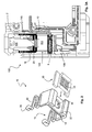
- a double tunnel terminal 1 placed in the housing 2 of a circuit breaker is illustrated in Figure 1A .
- the conductors are placed into a cage, or clamp, 3 of the terminal assembly 1 provided with a passage 4 therefor.
- a screw 5 is inserted within the clamp 3 to fasten the conductors 6.
- the screw 5 moves downwards for the free space available in the upper lodging based on the connection made in the upper lodging 4a and then moves upwards for the remaining available free space based on the connection made in the lower lodging 4b to ensure the tightening of the connection and during unscrewing the clamp 3 comes back to its position.
- the position of the screw 5 is different for different connection combination made in the upper and lower lodging 4 of the cage 3.
- the circuit breaker is often provided with a conventional connecter clip 7, which holds the screw 5 to the clamp 2.
- the double tunnel architecture is designed for utilizing the maximum space of the upper lodging capacity 4a, but this space remains partially occupied by the screw 5.
- Main drawback is thus that it is not flexible to adapt different capacity and dimensions of the electrical conductors and also fails to provide a uniform gripping between the multiple electrical conductors and the fixed connector, which leads to higher voltage drops.
- connection terminal architectures In order to optimize the user requirements, it is necessary to provide various connection terminal architectures to adapt to such multiple combinations of the conductors. This affects the modularity of the electrical apparatus, and requires complex and expensive arrangements, which results in delicate to manufacture, costly and bulky. Moreover, the mounting of the headed screw 5 on the clip 6 necessitates a clearance inside the assembly which leads to some tilting possibilities, and thus the right tightening of multiple connection with different sizes of cables may lead to the damage of the conventional connecter clip 6. Further, some of conventional approaches fail to provide ingress safety protection. Therefore, it is desirable to provide an assembly for multiple connection terminals in an electrical apparatus, which is capable of overcoming all the above-mentioned drawbacks and limitations.
- An object of the present invention is to provide an assembly for multiple connection terminals in an electrical apparatus, which is capable of providing highest reliability and flexibility to achieve uniform and larger space for insertion of multiple electrical conductors.
- Another object of the present invention is to provide an assembly for multiple connection terminals in an electrical apparatus, which is capable of providing a uniform gripping irrespective of size of the electrical conductors.
- a further object of the present invention is to provide an assembly for multiple connection terminals in an electrical apparatus, which enhances electrical contact between the electrical conductors.
- a further object of the present invention is to provide an assembly for multiple connection terminals in an electrical apparatus, which facilitates effective tightening of different cross-section electrical conductors without using any additional accessories.
- a further object of the present invention is to provide an assembly for multiple connection terminals in an electrical apparatus, which is simple, cost effective and integrated as single part.
- the invention relates to a terminal assembly and an electrical apparatus which achieve these objectives and which are defined in the appended claims.
- the present invention relates to an assembly for multiple connection terminals in an electrical apparatus comprising a protection plate arranged with a resilient portion at its both ends and an opening on its surface.
- a metallic part is configured with a gripping profile on its surface, where the metallic part is insert-molded or pressfitted with the protection plate.
- a clamp is formed with a through hole and a housing for receiving and securing multiple electrical conductors.
- a fastening means is secured against the through hole in the clamp and has a cylindrical or non-threaded tip to contact the metallic part through the opening in the protection plate.
- a fixed connector is placed inside the housing of the clamp in such a way that the housing of the clamp is divided into an upper and lower housing portions to provide separate lodging for clamping the electrical conductors.
- the protection plate with the metallic part is introduced into the housing of the clamp in such a way that the resilient portion of the protection plate faces away from the clamp.
- the fastening means is fastened on the clamp to press down the protection plate with the metallic part in relation to movement of the fastening means.
- the housing space of the clamp can be adjusted in accordance with dimensional variations of the electrical conductors being placed in both the upper and lower housing or in any one of the housing.
- the provision of the opening in the surface of the protection plate increases the thread engagement, when the full capacity of the clamp is utilized by the conductors. Also, the opening helps to transfer the entire tightening load directly to the metallic part being pressfitted or insert-molded with the protection plate.
- Such assembly provides highest reliability and flexibility to achieve uniform and larger space for insertion of multiple electrical conductors.
- the resilient portion of the protection plate is fixed to a casing of the electrical apparatus, such that the resilient portion of the protection plate holds the clamp even if the fastening means is completely disengaged from the clamp.
- the protection plate returns back to its original position due to the presence of resilient portion.
- the resilient portion of the protection plate is positioned inline with the outer surface of the electrical apparatus to provide ingress protection during the movement of the fastening means.
- the protection plate is made of an electrically non-conductive material, where the protection plate is a U-shaped protection plate.
- the clamp is also attached with a shutter for ingress protection at lower housing.
- the protection plate along with the metallic part gets tilted based on placement of the conductors to apply enough load to tight both the conductors properly.
- the metallic part has a gripping profile, which provides a uniform gripping while tightening the electrical conductors, where the electrical conductors comprise a cable and a bus bar.
- the fastening means is fastened onto the clamp after inserting the electrical conductors into the upper and lower housing portions of the clamp or in any one of the housing based on the requirements.
- the fastening means can move down the protection plate until it properly touches the fixed connector during no connection means in the upper housing, and during the connection means in the upper housing the fastening means move down the protection plate until it touches the conductors followed by tightening of it.
- the fastening means comprises a headed screw and a non-headed screw.
- the invention concerns an assembly for multiple connection terminals in an electrical apparatus, comprising a clamp formed with a through hole and a housing for receiving and securing multiple electrical conductors, a fastening means secured against the through hole in said clamp for fastening of electrical conductors, and a connecting clip having a upper surface and a lower surface, the upper surface being fixed with the fastening means and the lower surface being placed into the clamp wherein the upper and lower surface of the connecting clip is connected by means of a resilient means to enable the compression of the connecting clip in accordance to the position of the fastening means.
- the present invention relates to an electrical apparatus comprising a casing equipped with an assembly for multiple connection terminals described in the above embodiments.
- terminal assembly will be described in relation with this position of insertion shown in the figures, wherein the passage for connecting a conductor to the apparatus is lateral for horizontal insertion, and the fastening of the conductor inside the apparatus is performed by rotating a screw from an upper surface of the apparatus.
- position terms such as “horizontal”, “top”, “bottom” are in no way restrictive as to the object of the invention.
- geometric terms such as “orthogonal” etc. are to be understood in their mechanical acceptation, i.e. tolerating a deviation with respect to the strict mathematical definition.
- FIG. 2 shows an isometric view of a protection plate 10 in accordance with an exemplary embodiment of the present invention.
- the protection plate 10 is an ingress protection (IP) part, which is made of electrically non-conductive material, preferably plastic.
- IP ingress protection
- the plastic portion 12 of the protection plate 10 acts as an IP feature (finger safe, IP20) and comprises a support part 14 dedicated to cooperate with the screw 5 of the assembly and lateral part 16 which is located up the cooperating part 14 when the terminal 100 is arranged with the screw 105 fastened from the top of the housing 2 of the apparatus.
- the upper region 16 of the protection plate 10 is molded to form a resilient portion.
- the protection plate 10 is configured as U-shaped structure to provide flexibility on higher capacity for electrical conductors, and both sides 16 are spring-like, preferably with a Z shape or as a zigzagging element to allow compression perpendicular to the cooperating part 14. Furthermore, the cooperating part 14 of protection plate 10 is arranged with an opening 18 for insertion of fastening means 105.
- the protection plate 10 moreover comprises a base part 20 which is adapted to transfer the force of the fastening means to the conductors so as to avoid a direct contact of said conductors with a screw 105.
- the base part 14 is preferably metallic and the plastic portion 12 is formed in such a way that the metallic part 20 can be secured and inserted into the cooperating part 14, e.g. through grooves 22 which are molded.
- the metallic part 20 can also be press-fitted to the protection plate 10.
- the metallic part 20 is provided with a gripping profile 24 at its bottom surface, which provides a uniform gripping and gives a necessary strength to properly hold the electrical conductors while tightening.
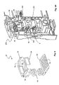
- the assembly terminal 100 for multiple connection provided with above protection plate 10 can be applied in the dedicated location of the casing 2 of electrical apparatuses, e.g. low voltage circuit breakers, as shown in Figures 3 .
- the assembly 100 comprises the protection plate 10 with the metallic part 20, a clamp 103, a fastening means 105 and a shutter 108.
- the protection plate 10 with the metallic part 20 can be introduced into the clamp 103 to enclose the inner surface of the clamp 103, where the resilient portion 16 of the protection plate 10 faces away from the clamp 103.
- the clamp 103 is formed with a conductor passage 104 for receiving and securing the electrical conductors.
- the top part of the clamp 103 can be shaped with a threaded hole, where the fastening means 105 can fully be threaded whereas the bottom part can be connected with the shutter 108 which acts as an IP feature.
- the fastening means 105 can be non-headed as per the maximum space requirement in the electrical apparatus.
- the fastening means 105 exhibits a cylindrical part, threaded over its length or not, that is chamfered at its tip 115 to provide unlimited torque at full disengagement condition.
- the tip portion 115 of the fastening means 105 is made in contact with the metallic part 20 through the opening 18 in the base part 16 of protection plate 10, which enables movement of the protection plate 10 within the conductor passage 104 in relation to movement of the fastening means 105.
- the opening 18 in the protection plate 10 facilitates maximum thread engagement of the fastening means 105 in threaded condition, when the full capacity of the clamp 103 is used by the electrical conductors and helps to transfer the entire tightening load directly to the metallic part 20.
- the entire assembly terminal 100 for the multiple connection is positioned in the casing 2 of the electrical apparatus.
- the fixed conductor 6 is situated in the conductor passage 104 so as to divide it into an upper housing portion 104a and a lower housing portion 104b, which provides a multiple tunnel feature.
- the upper housing portion 104a and the lower housing portion 104b allow the electrical conductors such as cable or busbar, in contact with the fixed connector 6 assembled in the casing 2 of the electrical apparatus.
- the similar assembly can be maintained on both sides of the electrical apparatus, particularly at top and bottom of the electrical apparatus.
- the upper and lower housing portions 104a, 104b are designed to provide separate lodging for clamping multiple electrical conductors, and the space can flexibly be adjusted in both the upper and lower housing portions 104a, 104b to optimize the customer requirements.
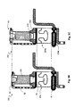
- the resilient portion 16 of the protection plate 10 is positioned inline with the outer surface of the electrical apparatus in order to provide ingress protection (IP40) against solid particle, for the upper housing portion 104a during the movement of fastening means 105.
- one end 26 of the resilient portion 16 is fixed to the casing 2, which acts as a reference point for the movement of resilient portion 16 in relation to the fastening means 105. Since the end 26 of the resilient portion 16 is fixed to the casing 2, the protection plate 10 holds the clamp 103 in fully opened condition, i.e. the fastening means 105 is fully disengaged from the clamp 103, as shown in Figure 3B . In such condition, the resilient portion 16 is in normal position to hold the clamp 103, which provides maximum space availability for insertion of multiple electrical conductors both in the upper and lower housing portions 104a, 104b. The maximum space availability of the assembly 100 can further be varied based on the customer requirement.
- the fastening means 105 is threaded into the clamp 103, which first moves up the clamp 103, such that the conductor, i.e. busbar, in the lower housing portion 104b is securely engaged with the fixed connecter 6. Then, the tip portion 115 of the fastening means 105 contacts the base part 20 through the opening 18 in the cooperating part 14. While tightening the fastening means 105, the cylindrical tip portion 115 presses the protection plate 10 located within the clamp 103, such that the protection plate 10 moves down with respect to the movement of the fastening means 105.
- the fastening means 105 moves the protection plate 10 until it reaches the fixed connector 6.
- the resilient portion 16 is in expanded position to completely occupy the conductor passage 104, which provides highest reliability and flexibility to enhance electrical contact between the electrical conductors.
- the expansion of the resilient portion 16 is designed in accordance with the conductor passage 104 in the clamp 103.
- Such resilient feature in the protection plate 10 provides flexibility to the space available in the terminal assembly 100 with different sizes of conductor diameter.
- the protection plate 10 elongates or reduces as per the size of conductor.
- the resilient feature in the protection plate 10 also facilitates effective tightening of different cross-section electrical conductors in the upper housing 104a due to balancing of the resilient portion 16 in the protection plate 10.
- the protection plate 10 returns back to its original position, which illustrates a cross sectional view depicting thread engagement of the fastening means 105 of the assembly 10 with the clamp 103, in accordance with an exemplary embodiment of the present invention.
- the fastening means 105 is still engaged with the clamp 103, which ensures maximum space at the upper housing portion 104a without utilizing any additional space at the lower housing portion 104b.
- the assembly further allows the user to fully disengage the fastening means 105 from the clamp 103, such that the fastening means 105 is freely suspended to move down the clamp 103, which makes gap in the lower housing portion 104b for electrical conductor insertion.
- FIG. 1 Some casings 2 of existing electrical apparatuses may not be convenient for the insertion and usage of former assembly 10 due e.g. to the absence of a wall in front of the extremity 26 of resilient part 16. It may be suitable to adapt former embodiment of the invention by providing a terminal assembly 200 made as a single entity with its protection plate 50.
- Figure 4 describes such a protection plate 50 according to a preferred embodiment of the invention; said protection plate 50 is near to the design of connecting clips 7.
- the protection plate 50 is provided with a resilient part 52 and a base part 54.
- the extremity 56 of the resilient part 52 opposite the base part 54 is provided with an upper part 58 suitable for cooperation with the fastening means 205 whereas the base part 54 is placed inside the clamp 203 for action on the conductors.
- the upper part 58 contains a hold portion 60 with a hole 62 for the fastening means 205 which is designed to accommodate a stepped or necked headed screw or a non-headed screw 205.
- the protection clip 50 is also supported and/or guided by the wall of the casing 2 at fully disengage condition thanks protrusions 64 on the upper part 58 which prevent it from tilting outwards.
- the base part 54 contains gripping profile 66 in the bottom surface to provide a uniform gripping for tightening of electrical conductors, and it can be associated with means allowing the assembly of an ingress protection component over it, to act as a shutter.
- Figure 5A describes the assembly 200 which has the connecting clip 50 in accordance with the present invention, said assembly 200 being placed inside a casing 2 of a circuit-breaker.
- the upper part 58 of the protection clip 50 is connected to the top end of the screw 205 and the lower part 54 is placed between the cage 203.
- the clip 50 is in the normal position during the disengaging of the screw 205. During the tightening of the screw 205, it compresses to accommodate the length of the screw 205; a pre-loaded condition can also be planed.
- the protection clip 50 thus always keeps the screw 205 in the required position during engaging, disengaging and transporting.
- a reduced stepped height screw 205 can be used which helps in reducing the screw head by 1.0 to 1.5 mm, thus reducing / eliminating the risk of IPxxb finger safe. Moreover, the fastening means 205 compresses the connection uniformly while the screw 205 sits over the top of the lower part 54 positioned in between the clamp 203.
- the bottom portion 54 of the clip 50 When the different sizes of the connection is placed in the same upper lodging 204a, the bottom portion 54 of the clip 50 get tilts to ensure full tightening of the connection. Upon removal of the screw load or disengaging of the screw 205, the base part 54 regains its original position to get ready for another set of connections. Due to this flexibility, the assembly 200 does not get damage at high application of tightening torque.
- the assembly terminal 200 When the screw 205 is at fully disengaged condition, the assembly terminal 200 according to the invention also provides the same maximal upper lodging capacity 204a as of usual connecting clip 6 featured terminal assemblies, but when the screw 205 is initially tightened for one or two rotations, the upper lodging capacity 204a is increased by 1.0 to 1.5 mm approximately thanks the spring back effect of the resilient part 52 of the protection plate 50 during initial tightening.
- the two positions showing difference in the height between screwed-in and disengaged are shown in Figures 5B and 5C . Since the resilient means 52 provide for change in height, the clip 50 accommodates such change in height.
Abstract
Description
- The present invention relates to the fields of connection of an electrical conductor to an electrical apparatus such as a circuit breaker. The present invention specifically relates to an assembly for multiple connection in the electrical apparatus.
- Many electrical applications require multiple connection terminal architecture to provide lodging and clamping of multiple electrical conductors such as cables, busbars, electrical wirings and the like. In particular, it is applicable for use in connection of multiple electrical conductors to the terminal assembly in the electrical apparatus such as circuit breaker. Most of the existing systems for clamping the electrical conductors are available as single tunnel terminal and bi-connect terminal.
- In the single tunnel terminal architecture, the screw is always placed above the fixed connector, and during its tightening the clamp moves upwards to tightens the connections: the screw remains in the same position for various connection combinations.
FR 2612340 EP 59939 - A double tunnel terminal 1 placed in the
housing 2 of a circuit breaker is illustrated inFigure 1A . The conductors are placed into a cage, or clamp, 3 of the terminal assembly 1 provided with apassage 4 therefor. Ascrew 5 is inserted within theclamp 3 to fasten theconductors 6. Thescrew 5 moves downwards for the free space available in the upper lodging based on the connection made in theupper lodging 4a and then moves upwards for the remaining available free space based on the connection made in thelower lodging 4b to ensure the tightening of the connection and during unscrewing theclamp 3 comes back to its position. Thus, in the double tunnel architecture, the position of thescrew 5 is different for different connection combination made in the upper andlower lodging 4 of thecage 3. However since thescrew 5 does not have any support, it is possible for thescrew 5 to fall out from thecage 3 at fully disengage condition. Therefore, as shown inFigure 1B , the circuit breaker is often provided with aconventional connecter clip 7, which holds thescrew 5 to theclamp 2. - These conventional assemblies are space consuming due to the design, which results in minimizing insertion space for the electrical conductors. Therefore, such terminal assemblies are not reliable to adapt multiple combinations of the conductors and are dedicated to a specific combination (e.g. one cable + one busbar) in accordance with the user requirements. Moreover, most of the conventional architectures are designed for the electrical conductors with a specific size. In particular, since the height of the
conventional connecter clip 7 is constant, it should be designed to appropriate size: too short, it would not allow the fully disengagement of thescrew 5 from theclamp 3 during unscrewing, and too long, it would let the screw head to disengage from theconventional connecter clip 7 at fully tightened condition, which lead to improper further engagement of theclip 7 with the screw head. Furthermore, the double tunnel architecture is designed for utilizing the maximum space of theupper lodging capacity 4a, but this space remains partially occupied by thescrew 5. Main drawback is thus that it is not flexible to adapt different capacity and dimensions of the electrical conductors and also fails to provide a uniform gripping between the multiple electrical conductors and the fixed connector, which leads to higher voltage drops. - In order to optimize the user requirements, it is necessary to provide various connection terminal architectures to adapt to such multiple combinations of the conductors. This affects the modularity of the electrical apparatus, and requires complex and expensive arrangements, which results in delicate to manufacture, costly and bulky. Moreover, the mounting of the
headed screw 5 on theclip 6 necessitates a clearance inside the assembly which leads to some tilting possibilities, and thus the right tightening of multiple connection with different sizes of cables may lead to the damage of theconventional connecter clip 6. Further, some of conventional approaches fail to provide ingress safety protection. Therefore, it is desirable to provide an assembly for multiple connection terminals in an electrical apparatus, which is capable of overcoming all the above-mentioned drawbacks and limitations. - An object of the present invention is to provide an assembly for multiple connection terminals in an electrical apparatus, which is capable of providing highest reliability and flexibility to achieve uniform and larger space for insertion of multiple electrical conductors.
- Another object of the present invention is to provide an assembly for multiple connection terminals in an electrical apparatus, which is capable of providing a uniform gripping irrespective of size of the electrical conductors.
- A further object of the present invention is to provide an assembly for multiple connection terminals in an electrical apparatus, which enhances electrical contact between the electrical conductors.
- A further object of the present invention is to provide an assembly for multiple connection terminals in an electrical apparatus, which facilitates effective tightening of different cross-section electrical conductors without using any additional accessories.
- A further object of the present invention is to provide an assembly for multiple connection terminals in an electrical apparatus, which is simple, cost effective and integrated as single part.
- The invention relates to a terminal assembly and an electrical apparatus which achieve these objectives and which are defined in the appended claims.
- According to a preferred embodiment, the present invention relates to an assembly for multiple connection terminals in an electrical apparatus comprising a protection plate arranged with a resilient portion at its both ends and an opening on its surface. A metallic part is configured with a gripping profile on its surface, where the metallic part is insert-molded or pressfitted with the protection plate. A clamp is formed with a through hole and a housing for receiving and securing multiple electrical conductors. A fastening means is secured against the through hole in the clamp and has a cylindrical or non-threaded tip to contact the metallic part through the opening in the protection plate. A fixed connector is placed inside the housing of the clamp in such a way that the housing of the clamp is divided into an upper and lower housing portions to provide separate lodging for clamping the electrical conductors. The protection plate with the metallic part is introduced into the housing of the clamp in such a way that the resilient portion of the protection plate faces away from the clamp. The fastening means is fastened on the clamp to press down the protection plate with the metallic part in relation to movement of the fastening means. The housing space of the clamp can be adjusted in accordance with dimensional variations of the electrical conductors being placed in both the upper and lower housing or in any one of the housing. The provision of the opening in the surface of the protection plate increases the thread engagement, when the full capacity of the clamp is utilized by the conductors. Also, the opening helps to transfer the entire tightening load directly to the metallic part being pressfitted or insert-molded with the protection plate. Such assembly provides highest reliability and flexibility to achieve uniform and larger space for insertion of multiple electrical conductors.
- Furthermore, the resilient portion of the protection plate is fixed to a casing of the electrical apparatus, such that the resilient portion of the protection plate holds the clamp even if the fastening means is completely disengaged from the clamp. When the fastening means is disengaged from the clamp, the protection plate returns back to its original position due to the presence of resilient portion. The resilient portion of the protection plate is positioned inline with the outer surface of the electrical apparatus to provide ingress protection during the movement of the fastening means. The protection plate is made of an electrically non-conductive material, where the protection plate is a U-shaped protection plate. The clamp is also attached with a shutter for ingress protection at lower housing.
- Moreover, when ever two conductors of different cross section are placed and tightened inside the upper housing of the clamp, due to the flexibility provided by the resilient portion, the protection plate along with the metallic part gets tilted based on placement of the conductors to apply enough load to tight both the conductors properly. The metallic part has a gripping profile, which provides a uniform gripping while tightening the electrical conductors, where the electrical conductors comprise a cable and a bus bar. The fastening means is fastened onto the clamp after inserting the electrical conductors into the upper and lower housing portions of the clamp or in any one of the housing based on the requirements. The fastening means can move down the protection plate until it properly touches the fixed connector during no connection means in the upper housing, and during the connection means in the upper housing the fastening means move down the protection plate until it touches the conductors followed by tightening of it. The fastening means comprises a headed screw and a non-headed screw.
- In another preferred embodiment, the invention concerns an assembly for multiple connection terminals in an electrical apparatus, comprising a clamp formed with a through hole and a housing for receiving and securing multiple electrical conductors, a fastening means secured against the through hole in said clamp for fastening of electrical conductors, and a connecting clip having a upper surface and a lower surface, the upper surface being fixed with the fastening means and the lower surface being placed into the clamp wherein the upper and lower surface of the connecting clip is connected by means of a resilient means to enable the compression of the connecting clip in accordance to the position of the fastening means.
- According to another aspect, the present invention relates to an electrical apparatus comprising a casing equipped with an assembly for multiple connection terminals described in the above embodiments.
- Other advantages and features will become more clearly apparent from the following description of particular embodiments of the invention, given for illustrative and non-restrictive example purposes only and represented in the accompanying drawings.
-
Figures 1A and 1B show a conventional double tunnel terminal for circuit breaker, both with and without a conventional connecter clip and cover. -
Figure 2 shows an isometric view of a protection plate arranged with a metallic part, in accordance with an exemplary embodiment of the present invention; -
Figures 3A ,3B and 3C illustrate the assembly for multiple connection terminals engaged with a casing in a fully opened and a fully closed conditions, in accordance with an exemplary embodiment of the present invention; -
Figure 4 shows a connecting clip according to an embodiment of the present invention. -
Figures 5A ,5B and 5C show the assembly with the connecting clip according to the invention in screw engaged position and disengaged position. - For the sake of simplification of description of the embodiments according to the invention, terminal assembly will be described in relation with this position of insertion shown in the figures, wherein the passage for connecting a conductor to the apparatus is lateral for horizontal insertion, and the fastening of the conductor inside the apparatus is performed by rotating a screw from an upper surface of the apparatus. It is however understood that the position terms such as "horizontal", "top", "bottom" are in no way restrictive as to the object of the invention. Moreover, geometric terms such as "orthogonal" etc. are to be understood in their mechanical acceptation, i.e. tolerating a deviation with respect to the strict mathematical definition. Some wordings may be replaced by equivalent and have to be considered regarding the function they define in the technical features they represent.
-
Figure 2 shows an isometric view of aprotection plate 10 in accordance with an exemplary embodiment of the present invention. Theprotection plate 10 is an ingress protection (IP) part, which is made of electrically non-conductive material, preferably plastic. Theplastic portion 12 of theprotection plate 10 acts as an IP feature (finger safe, IP20) and comprises asupport part 14 dedicated to cooperate with thescrew 5 of the assembly andlateral part 16 which is located up the cooperatingpart 14 when the terminal 100 is arranged with thescrew 105 fastened from the top of thehousing 2 of the apparatus. Theupper region 16 of theprotection plate 10 is molded to form a resilient portion. Preferably theprotection plate 10 is configured as U-shaped structure to provide flexibility on higher capacity for electrical conductors, and bothsides 16 are spring-like, preferably with a Z shape or as a zigzagging element to allow compression perpendicular to the cooperatingpart 14. Furthermore, the cooperatingpart 14 ofprotection plate 10 is arranged with anopening 18 for insertion of fastening means 105. - The
protection plate 10 moreover comprises abase part 20 which is adapted to transfer the force of the fastening means to the conductors so as to avoid a direct contact of said conductors with ascrew 105. Thebase part 14 is preferably metallic and theplastic portion 12 is formed in such a way that themetallic part 20 can be secured and inserted into the cooperatingpart 14, e.g. throughgrooves 22 which are molded. Themetallic part 20 can also be press-fitted to theprotection plate 10. Themetallic part 20 is provided with a grippingprofile 24 at its bottom surface, which provides a uniform gripping and gives a necessary strength to properly hold the electrical conductors while tightening. - The
assembly terminal 100 for multiple connection provided withabove protection plate 10 can be applied in the dedicated location of thecasing 2 of electrical apparatuses, e.g. low voltage circuit breakers, as shown inFigures 3 . Theassembly 100 comprises theprotection plate 10 with themetallic part 20, aclamp 103, a fastening means 105 and ashutter 108. Theprotection plate 10 with themetallic part 20 can be introduced into theclamp 103 to enclose the inner surface of theclamp 103, where theresilient portion 16 of theprotection plate 10 faces away from theclamp 103. Theclamp 103 is formed with aconductor passage 104 for receiving and securing the electrical conductors. The top part of theclamp 103 can be shaped with a threaded hole, where the fastening means 105 can fully be threaded whereas the bottom part can be connected with theshutter 108 which acts as an IP feature. - Although represented here as a headed
screw 105, the fastening means 105 can be non-headed as per the maximum space requirement in the electrical apparatus. The fastening means 105 exhibits a cylindrical part, threaded over its length or not, that is chamfered at itstip 115 to provide unlimited torque at full disengagement condition. Further, thetip portion 115 of the fastening means 105 is made in contact with themetallic part 20 through theopening 18 in thebase part 16 ofprotection plate 10, which enables movement of theprotection plate 10 within theconductor passage 104 in relation to movement of the fastening means 105. Theopening 18 in theprotection plate 10 facilitates maximum thread engagement of the fastening means 105 in threaded condition, when the full capacity of theclamp 103 is used by the electrical conductors and helps to transfer the entire tightening load directly to themetallic part 20. - The
entire assembly terminal 100 for the multiple connection is positioned in thecasing 2 of the electrical apparatus. The fixedconductor 6 is situated in theconductor passage 104 so as to divide it into anupper housing portion 104a and alower housing portion 104b, which provides a multiple tunnel feature. Theupper housing portion 104a and thelower housing portion 104b allow the electrical conductors such as cable or busbar, in contact with the fixedconnector 6 assembled in thecasing 2 of the electrical apparatus. The similar assembly can be maintained on both sides of the electrical apparatus, particularly at top and bottom of the electrical apparatus. - In addition, the upper and
lower housing portions lower housing portions resilient portion 16 of theprotection plate 10 is positioned inline with the outer surface of the electrical apparatus in order to provide ingress protection (IP40) against solid particle, for theupper housing portion 104a during the movement of fastening means 105. - Moreover, one
end 26 of theresilient portion 16 is fixed to thecasing 2, which acts as a reference point for the movement ofresilient portion 16 in relation to the fastening means 105. Since theend 26 of theresilient portion 16 is fixed to thecasing 2, theprotection plate 10 holds theclamp 103 in fully opened condition, i.e. the fastening means 105 is fully disengaged from theclamp 103, as shown inFigure 3B . In such condition, theresilient portion 16 is in normal position to hold theclamp 103, which provides maximum space availability for insertion of multiple electrical conductors both in the upper andlower housing portions assembly 100 can further be varied based on the customer requirement. - Referring to
Figure 3C , the fully closed condition is illustrated. Initially, the fastening means 105 is threaded into theclamp 103, which first moves up theclamp 103, such that the conductor, i.e. busbar, in thelower housing portion 104b is securely engaged with the fixedconnecter 6. Then, thetip portion 115 of the fastening means 105 contacts thebase part 20 through theopening 18 in the cooperatingpart 14. While tightening the fastening means 105, thecylindrical tip portion 115 presses theprotection plate 10 located within theclamp 103, such that theprotection plate 10 moves down with respect to the movement of the fastening means 105. - In fully closed condition when there are no conductors in the
upper housing 104a, the fastening means 105 moves theprotection plate 10 until it reaches the fixedconnector 6. In such condition, theresilient portion 16 is in expanded position to completely occupy theconductor passage 104, which provides highest reliability and flexibility to enhance electrical contact between the electrical conductors. The expansion of theresilient portion 16 is designed in accordance with theconductor passage 104 in theclamp 103. Such resilient feature in theprotection plate 10 provides flexibility to the space available in theterminal assembly 100 with different sizes of conductor diameter. Theprotection plate 10 elongates or reduces as per the size of conductor. The resilient feature in theprotection plate 10 also facilitates effective tightening of different cross-section electrical conductors in theupper housing 104a due to balancing of theresilient portion 16 in theprotection plate 10. - When the fastening means is unscrewed or loosened from the
clamp 103, theprotection plate 10 returns back to its original position, which illustrates a cross sectional view depicting thread engagement of the fastening means 105 of theassembly 10 with theclamp 103, in accordance with an exemplary embodiment of the present invention. In such condition, the fastening means 105 is still engaged with theclamp 103, which ensures maximum space at theupper housing portion 104a without utilizing any additional space at thelower housing portion 104b. The assembly further allows the user to fully disengage the fastening means 105 from theclamp 103, such that the fastening means 105 is freely suspended to move down theclamp 103, which makes gap in thelower housing portion 104b for electrical conductor insertion. Even though the fastening means 105 is freely suspended, it never comes out of thecasing 2 and is also pointed in thepassage 104 of theclamp 103 due to itsextended tip portion 115.Such assembly 100 for the multiple connection terminals is simple, cost effective and integrated as single part. - Some
casings 2 of existing electrical apparatuses may not be convenient for the insertion and usage offormer assembly 10 due e.g. to the absence of a wall in front of theextremity 26 ofresilient part 16. It may be suitable to adapt former embodiment of the invention by providing aterminal assembly 200 made as a single entity with itsprotection plate 50.Figure 4 describes such aprotection plate 50 according to a preferred embodiment of the invention; saidprotection plate 50 is near to the design of connectingclips 7. Similarly, theprotection plate 50 is provided with aresilient part 52 and abase part 54. Theextremity 56 of theresilient part 52 opposite thebase part 54 is provided with anupper part 58 suitable for cooperation with the fastening means 205 whereas thebase part 54 is placed inside theclamp 203 for action on the conductors. Theupper part 58 contains ahold portion 60 with ahole 62 for the fastening means 205 which is designed to accommodate a stepped or necked headed screw or anon-headed screw 205. Advantageously, theprotection clip 50 is also supported and/or guided by the wall of thecasing 2 at fully disengage condition thanks protrusions 64 on theupper part 58 which prevent it from tilting outwards. Thebase part 54 contains grippingprofile 66 in the bottom surface to provide a uniform gripping for tightening of electrical conductors, and it can be associated with means allowing the assembly of an ingress protection component over it, to act as a shutter. -
Figure 5A describes theassembly 200 which has the connectingclip 50 in accordance with the present invention, saidassembly 200 being placed inside acasing 2 of a circuit-breaker. Theupper part 58 of theprotection clip 50 is connected to the top end of thescrew 205 and thelower part 54 is placed between thecage 203. Theclip 50 is in the normal position during the disengaging of thescrew 205. During the tightening of thescrew 205, it compresses to accommodate the length of thescrew 205; a pre-loaded condition can also be planed. Theprotection clip 50 thus always keeps thescrew 205 in the required position during engaging, disengaging and transporting. Due to thisresilient feature 52 of the side a reduced steppedheight screw 205 can be used which helps in reducing the screw head by 1.0 to 1.5 mm, thus reducing / eliminating the risk of IPxxb finger safe. Moreover, the fastening means 205 compresses the connection uniformly while thescrew 205 sits over the top of thelower part 54 positioned in between theclamp 203. - When the different sizes of the connection is placed in the same
upper lodging 204a, thebottom portion 54 of theclip 50 get tilts to ensure full tightening of the connection. Upon removal of the screw load or disengaging of thescrew 205, thebase part 54 regains its original position to get ready for another set of connections. Due to this flexibility, theassembly 200 does not get damage at high application of tightening torque. - When the
screw 205 is at fully disengaged condition, theassembly terminal 200 according to the invention also provides the same maximalupper lodging capacity 204a as of usual connectingclip 6 featured terminal assemblies, but when thescrew 205 is initially tightened for one or two rotations, theupper lodging capacity 204a is increased by 1.0 to 1.5 mm approximately thanks the spring back effect of theresilient part 52 of theprotection plate 50 during initial tightening. The two positions showing difference in the height between screwed-in and disengaged are shown inFigures 5B and 5C . Since the resilient means 52 provide for change in height, theclip 50 accommodates such change in height. - The foregoing description of the preferred embodiments of the present invention has been presented for purposes of illustration and description: It is not intended to be exhaustive or to limit the invention to the precise form. In particular, some characteristics disclosed in combination may be used individually or replaced by their equivalents and the characteristics of the first embodiment might be used in combination with other characteristics of the second embodiment, and vice versa: many modifications: variations will be apparent to practitioners skilled in this art and the scope of the invention is defined by the claims.
Claims (11)
- Terminal assembly (100, 200) for multiple connections in an electrical apparatus comprising:- a clamp (103, 203) defining a passage (104, 204) for receiving and securing multiple electrical conductors and formed with a hole;- a fastening means (105, 205) cooperating with the clamp (103, 203), comprising a tip (115, 215) at an extremity of a cylindrical part able to penetrate the hole of the clamp (103, 203);- a protection plate (10, 50) comprising a base part (20, 54) adapted for introduction into the passage (104, 204) of the clamp (103, 203), a resilient portion (12, 52) extending from the base part (20, 54) and sensibly orthogonal thereto, and a cooperating plate (14, 58) with a hole (18, 62) for the fastening means (105, 205), said cooperating plate (14, 58) being sensibly parallel to the base part (20, 54) and coupled to the resilient portion (12, 52);- wherein, when the terminal (100, 200) is assembled, the cylindrical part of the fastening means (105, 205) passes through both holes (18, 62) of the clamp (103, 203) and the cooperating plate (14, 58), the cylindrical part of the fastening means (105, 205) is sensibly parallel to the resilient portion (12, 52) and the tip (115, 215) of the fastening means (105, 205) is adjacent to the base part (20, 54) which is located inside the passage (104, 204) of the clamp (103, 203), said fastening means (105, 205) being able to move relatively to the resilient portion (12, 52) so that the pressure exerted by the tip (115, 215) on the base part (20, 54) can vary and the passage (104, 204) of the clamp (103, 203) is adjusted to dimensional variations.
- The assembly according to claim 1 wherein the base part (20, 54) is provided with a gripping profile (24, 66) on the surface opposite the tip (115, 215) of the fastening means (105, 205).
- The assembly according to claim 1 or claim 2 further comprising a shutter (108) attached to the clamp (103, 203) for ingress protection.
- The assembly according to one of claims 1 to 3 wherein the resilient portion (12, 52) comprises a zigzagging spring which compression force is parallel to the cylindrical part of the fastening means (105, 205).
- The assembly according to one of claims 1 to 4 wherein the base part (20) and the cooperating part (14) are located on the same extremity of the resilient portion (12).
- The assembly according to claim 5 wherein the resilient portion (12) and the cooperating part (14) are made of an electrically non-conductive material, and the base part (20) is made of electrically conductive material.
- The assembly according to claim 5 or claim 6 wherein the protection plate (10) has a U-shape, with two sensibly identical resilient portions (12) opposite two sides of the cooperating part (14)
- The terminal assembly according to any of claims 1 to 4 wherein the cooperating part (58) and the base part (54) are coupled to both extremities of the resilient portion (52) so as to form a U.
- An electrical apparatus comprising a casing (2) equipped with a terminal assembly (100, 200) according to any one of the preceding claims, and a fixed conductor (6) located within the passage (104, 204) of the clamp (103, 203) of the terminal assembly (100, 200).
- An electrical apparatus comprising a casing (2) equipped with a terminal assembly (100) according to any of claims 5 to 7, wherein the extremity (26) of the resilient part (12) opposite the cooperating part (14) of the protection plate (10) of the terminal assembly (100) is in contact with a fixed part of the casing (2).
- The apparatus according to claim 10 or claim 11 wherein the resilient portion (12, 52) of the protection plate (10, 50) is positioned inline with the outer surface of the electrical apparatus to provide ingress protection during the movement of the fastening means (105, 205).
Applications Claiming Priority (2)
| Application Number | Priority Date | Filing Date | Title |
|---|---|---|---|
| IN2588CH2009 | 2009-10-26 | ||
| IN2642CH2009 | 2009-10-30 |
Publications (2)
| Publication Number | Publication Date |
|---|---|
| EP2315313A1 true EP2315313A1 (en) | 2011-04-27 |
| EP2315313B1 EP2315313B1 (en) | 2012-02-08 |
Family
ID=43416921
Family Applications (1)
| Application Number | Title | Priority Date | Filing Date |
|---|---|---|---|
| EP10354051A Active EP2315313B1 (en) | 2009-10-26 | 2010-09-20 | Assembly for multiple connection in an electrical apparatus |
Country Status (3)
| Country | Link |
|---|---|
| EP (1) | EP2315313B1 (en) |
| CN (1) | CN102055080B (en) |
| AT (1) | ATE545175T1 (en) |
Cited By (4)
| Publication number | Priority date | Publication date | Assignee | Title |
|---|---|---|---|---|
| CN103887124A (en) * | 2014-03-12 | 2014-06-25 | 科都电气有限公司 | Micro breaker |
| EP2903015A4 (en) * | 2012-09-25 | 2016-06-08 | Noark Electrics Shanghai Co Ltd | Circuit breaker |
| WO2017016751A1 (en) * | 2015-07-29 | 2017-02-02 | Wago Verwaltungsgesellschaft Mbh | Conductor connection terminal |
| EP3333981A1 (en) * | 2016-12-09 | 2018-06-13 | Schneider Electric Industries SAS | Electrical connecting terminal between two conducting elements |
Families Citing this family (3)
| Publication number | Priority date | Publication date | Assignee | Title |
|---|---|---|---|---|
| CN103177909B (en) * | 2011-12-26 | 2016-03-30 | 西门子公司 | Termination |
| DE202014006691U1 (en) * | 2014-08-18 | 2014-10-27 | Dehn + Söhne Gmbh + Co. Kg | Electrical connection terminal |
| IT201600084041A1 (en) * | 2016-08-09 | 2018-02-09 | Gewiss Spa | AUXILIARY CONTACT STRUCTURE |
Citations (5)
| Publication number | Priority date | Publication date | Assignee | Title |
|---|---|---|---|---|
| FR2358575A1 (en) * | 1976-07-16 | 1978-02-10 | Kedves Louis | Terminal block assembly with screw clamp - includes plate to protect end of wire from rotating end of clamping screw |
| EP0059939A1 (en) | 1981-03-10 | 1982-09-15 | BROWN, BOVERI & CIE Aktiengesellschaft | Terminal for the connection of electrical conductors |
| FR2612340A1 (en) | 1987-03-13 | 1988-09-16 | Merlin Gerin | Multiple connection terminal for a modular electrical apparatus |
| EP1796214A1 (en) * | 2005-12-09 | 2007-06-13 | Schneider Electric Industries Sas | Electrical connection terminal and circuit breaker device with such a terminal |
| EP1916740A1 (en) * | 2006-10-28 | 2008-04-30 | ABB PATENT GmbH | Installation switching device and connecting terminal for an installation switching device |
Family Cites Families (4)
| Publication number | Priority date | Publication date | Assignee | Title |
|---|---|---|---|---|
| DE10131975A1 (en) * | 2001-07-02 | 2003-01-30 | Siemens Ag | terminal |
| CN2704915Y (en) * | 2004-06-30 | 2005-06-15 | 温州奥来电气有限公司 | Circuit breakers |
| DE102005052982B4 (en) * | 2005-11-07 | 2007-11-08 | Siemens Ag | Clamping device for a DIN rail mounted device |
| DE102007006367A1 (en) * | 2007-02-08 | 2008-08-21 | Siemens Ag | Circuit breaker with terminal |
-
2010
- 2010-09-20 AT AT10354051T patent/ATE545175T1/en active
- 2010-09-20 EP EP10354051A patent/EP2315313B1/en active Active
- 2010-10-26 CN CN201010524537.XA patent/CN102055080B/en active Active
Patent Citations (5)
| Publication number | Priority date | Publication date | Assignee | Title |
|---|---|---|---|---|
| FR2358575A1 (en) * | 1976-07-16 | 1978-02-10 | Kedves Louis | Terminal block assembly with screw clamp - includes plate to protect end of wire from rotating end of clamping screw |
| EP0059939A1 (en) | 1981-03-10 | 1982-09-15 | BROWN, BOVERI & CIE Aktiengesellschaft | Terminal for the connection of electrical conductors |
| FR2612340A1 (en) | 1987-03-13 | 1988-09-16 | Merlin Gerin | Multiple connection terminal for a modular electrical apparatus |
| EP1796214A1 (en) * | 2005-12-09 | 2007-06-13 | Schneider Electric Industries Sas | Electrical connection terminal and circuit breaker device with such a terminal |
| EP1916740A1 (en) * | 2006-10-28 | 2008-04-30 | ABB PATENT GmbH | Installation switching device and connecting terminal for an installation switching device |
Cited By (7)
| Publication number | Priority date | Publication date | Assignee | Title |
|---|---|---|---|---|
| EP2903015A4 (en) * | 2012-09-25 | 2016-06-08 | Noark Electrics Shanghai Co Ltd | Circuit breaker |
| US9490092B2 (en) | 2012-09-25 | 2016-11-08 | Noark Electrics (Shanghai) Co., Ltd. | Circuit breaker |
| CN103887124A (en) * | 2014-03-12 | 2014-06-25 | 科都电气有限公司 | Micro breaker |
| WO2017016751A1 (en) * | 2015-07-29 | 2017-02-02 | Wago Verwaltungsgesellschaft Mbh | Conductor connection terminal |
| EP3333981A1 (en) * | 2016-12-09 | 2018-06-13 | Schneider Electric Industries SAS | Electrical connecting terminal between two conducting elements |
| FR3060216A1 (en) * | 2016-12-09 | 2018-06-15 | Schneider Electric Industries Sas | ELECTRICAL CONNECTION TERMINAL BETWEEN TWO CONDUCTIVE ELEMENTS |
| US10177470B2 (en) | 2016-12-09 | 2019-01-08 | Schneider Electric Industries Sas | Electrical connection terminal between two conductive elements |
Also Published As
| Publication number | Publication date |
|---|---|
| CN102055080B (en) | 2014-12-17 |
| CN102055080A (en) | 2011-05-11 |
| ATE545175T1 (en) | 2012-02-15 |
| EP2315313B1 (en) | 2012-02-08 |
Similar Documents
| Publication | Publication Date | Title |
|---|---|---|
| EP2315313B1 (en) | Assembly for multiple connection in an electrical apparatus | |
| EP1936743B1 (en) | Double connection terminal screw/plug-in for electrical apparatus | |
| RU2416845C2 (en) | Electric terminal and electric switchgear containing one such terminal | |
| US8602829B2 (en) | Cable connector with integrated shoe | |
| US4775122A (en) | Cable clamp | |
| US10027041B2 (en) | Electrical apparatus having a push-in connection terminal with a support clip guiding and limiting the elastic deformation of the contact spring | |
| US10374337B2 (en) | Terminal block | |
| CN101552390A (en) | Connector with a shielding-screen support | |
| CN107851923A (en) | The arrangements of electric connection for connecting more cables of F. O. D can be defendd | |
| US20100255701A1 (en) | Bus bar connector terminal design | |
| CN111357154A (en) | Connecting device and method for connecting conductors, in particular shielding conductors, to an electronics housing | |
| CN108475857B (en) | Bus tapping clamp with clamping spring technology | |
| US3452317A (en) | Clamp-type terminal | |
| US4743204A (en) | Auxiliary bolt-operated connection for panelboard circuit breaker | |
| US20110312208A1 (en) | Push-in connector for accepting the end of a rigid conductor | |
| KR102249090B1 (en) | Mounting frame with PE-contact | |
| US6094357A (en) | Product having a rechargeable battery which is held in a mechanically stable manner and is easy to remove | |
| CN110622359B (en) | Connecting device for connecting at least one electrical conductor to a screw terminal | |
| CN110931991A (en) | Split type conductive clamping mechanism and wiring terminal with same | |
| CN111816518B (en) | Binding post and circuit breaker | |
| EP3940880A1 (en) | Battery terminal | |
| US11670877B2 (en) | Grounding clamp with lateral anti-twist protection | |
| CN111656616B (en) | Electrical terminal with cage clamp for cable termination | |
| KR101830420B1 (en) | Joint connector | |
| JP2007507839A (en) | Device for fixing conductive rails for polyphase switching devices |
Legal Events
| Date | Code | Title | Description |
|---|---|---|---|
| PUAI | Public reference made under article 153(3) epc to a published international application that has entered the european phase |
Free format text: ORIGINAL CODE: 0009012 |
|
| AK | Designated contracting states |
Kind code of ref document: A1 Designated state(s): AL AT BE BG CH CY CZ DE DK EE ES FI FR GB GR HR HU IE IS IT LI LT LU LV MC MK MT NL NO PL PT RO SE SI SK SM TR |
|
| AX | Request for extension of the european patent |
Extension state: BA ME RS |
|
| 17P | Request for examination filed |
Effective date: 20110516 |
|
| GRAP | Despatch of communication of intention to grant a patent |
Free format text: ORIGINAL CODE: EPIDOSNIGR1 |
|
| RIC1 | Information provided on ipc code assigned before grant |
Ipc: H01R 4/36 20060101AFI20110712BHEP |
|
| GRAC | Information related to communication of intention to grant a patent modified |
Free format text: ORIGINAL CODE: EPIDOSCIGR1 |
|
| GRAS | Grant fee paid |
Free format text: ORIGINAL CODE: EPIDOSNIGR3 |
|
| GRAA | (expected) grant |
Free format text: ORIGINAL CODE: 0009210 |
|
| AK | Designated contracting states |
Kind code of ref document: B1 Designated state(s): AL AT BE BG CH CY CZ DE DK EE ES FI FR GB GR HR HU IE IS IT LI LT LU LV MC MK MT NL NO PL PT RO SE SI SK SM TR |
|
| REG | Reference to a national code |
Ref country code: GB Ref legal event code: FG4D |
|
| REG | Reference to a national code |
Ref country code: CH Ref legal event code: EP Ref country code: AT Ref legal event code: REF Ref document number: 545175 Country of ref document: AT Kind code of ref document: T Effective date: 20120215 |
|
| REG | Reference to a national code |
Ref country code: DE Ref legal event code: R096 Ref document number: 602010000835 Country of ref document: DE Effective date: 20120405 |
|
| REG | Reference to a national code |
Ref country code: NL Ref legal event code: VDEP Effective date: 20120208 |
|
| LTIE | Lt: invalidation of european patent or patent extension |
Effective date: 20120208 |
|
| PG25 | Lapsed in a contracting state [announced via postgrant information from national office to epo] |
Ref country code: NL Free format text: LAPSE BECAUSE OF FAILURE TO SUBMIT A TRANSLATION OF THE DESCRIPTION OR TO PAY THE FEE WITHIN THE PRESCRIBED TIME-LIMIT Effective date: 20120208 Ref country code: HR Free format text: LAPSE BECAUSE OF FAILURE TO SUBMIT A TRANSLATION OF THE DESCRIPTION OR TO PAY THE FEE WITHIN THE PRESCRIBED TIME-LIMIT Effective date: 20120208 Ref country code: LT Free format text: LAPSE BECAUSE OF FAILURE TO SUBMIT A TRANSLATION OF THE DESCRIPTION OR TO PAY THE FEE WITHIN THE PRESCRIBED TIME-LIMIT Effective date: 20120208 Ref country code: NO Free format text: LAPSE BECAUSE OF FAILURE TO SUBMIT A TRANSLATION OF THE DESCRIPTION OR TO PAY THE FEE WITHIN THE PRESCRIBED TIME-LIMIT Effective date: 20120508 Ref country code: IS Free format text: LAPSE BECAUSE OF FAILURE TO SUBMIT A TRANSLATION OF THE DESCRIPTION OR TO PAY THE FEE WITHIN THE PRESCRIBED TIME-LIMIT Effective date: 20120608 |
|
| PG25 | Lapsed in a contracting state [announced via postgrant information from national office to epo] |
Ref country code: GR Free format text: LAPSE BECAUSE OF FAILURE TO SUBMIT A TRANSLATION OF THE DESCRIPTION OR TO PAY THE FEE WITHIN THE PRESCRIBED TIME-LIMIT Effective date: 20120509 Ref country code: PT Free format text: LAPSE BECAUSE OF FAILURE TO SUBMIT A TRANSLATION OF THE DESCRIPTION OR TO PAY THE FEE WITHIN THE PRESCRIBED TIME-LIMIT Effective date: 20120608 Ref country code: BE Free format text: LAPSE BECAUSE OF FAILURE TO SUBMIT A TRANSLATION OF THE DESCRIPTION OR TO PAY THE FEE WITHIN THE PRESCRIBED TIME-LIMIT Effective date: 20120208 Ref country code: LV Free format text: LAPSE BECAUSE OF FAILURE TO SUBMIT A TRANSLATION OF THE DESCRIPTION OR TO PAY THE FEE WITHIN THE PRESCRIBED TIME-LIMIT Effective date: 20120208 Ref country code: PL Free format text: LAPSE BECAUSE OF FAILURE TO SUBMIT A TRANSLATION OF THE DESCRIPTION OR TO PAY THE FEE WITHIN THE PRESCRIBED TIME-LIMIT Effective date: 20120208 Ref country code: FI Free format text: LAPSE BECAUSE OF FAILURE TO SUBMIT A TRANSLATION OF THE DESCRIPTION OR TO PAY THE FEE WITHIN THE PRESCRIBED TIME-LIMIT Effective date: 20120208 |
|
| REG | Reference to a national code |
Ref country code: AT Ref legal event code: MK05 Ref document number: 545175 Country of ref document: AT Kind code of ref document: T Effective date: 20120208 |
|
| PG25 | Lapsed in a contracting state [announced via postgrant information from national office to epo] |
Ref country code: CY Free format text: LAPSE BECAUSE OF FAILURE TO SUBMIT A TRANSLATION OF THE DESCRIPTION OR TO PAY THE FEE WITHIN THE PRESCRIBED TIME-LIMIT Effective date: 20120208 |
|
| PG25 | Lapsed in a contracting state [announced via postgrant information from national office to epo] |
Ref country code: RO Free format text: LAPSE BECAUSE OF FAILURE TO SUBMIT A TRANSLATION OF THE DESCRIPTION OR TO PAY THE FEE WITHIN THE PRESCRIBED TIME-LIMIT Effective date: 20120208 Ref country code: EE Free format text: LAPSE BECAUSE OF FAILURE TO SUBMIT A TRANSLATION OF THE DESCRIPTION OR TO PAY THE FEE WITHIN THE PRESCRIBED TIME-LIMIT Effective date: 20120208 Ref country code: SE Free format text: LAPSE BECAUSE OF FAILURE TO SUBMIT A TRANSLATION OF THE DESCRIPTION OR TO PAY THE FEE WITHIN THE PRESCRIBED TIME-LIMIT Effective date: 20120208 Ref country code: DK Free format text: LAPSE BECAUSE OF FAILURE TO SUBMIT A TRANSLATION OF THE DESCRIPTION OR TO PAY THE FEE WITHIN THE PRESCRIBED TIME-LIMIT Effective date: 20120208 Ref country code: SI Free format text: LAPSE BECAUSE OF FAILURE TO SUBMIT A TRANSLATION OF THE DESCRIPTION OR TO PAY THE FEE WITHIN THE PRESCRIBED TIME-LIMIT Effective date: 20120208 Ref country code: CZ Free format text: LAPSE BECAUSE OF FAILURE TO SUBMIT A TRANSLATION OF THE DESCRIPTION OR TO PAY THE FEE WITHIN THE PRESCRIBED TIME-LIMIT Effective date: 20120208 |
|
| PG25 | Lapsed in a contracting state [announced via postgrant information from national office to epo] |
Ref country code: IT Free format text: LAPSE BECAUSE OF FAILURE TO SUBMIT A TRANSLATION OF THE DESCRIPTION OR TO PAY THE FEE WITHIN THE PRESCRIBED TIME-LIMIT Effective date: 20120208 Ref country code: SK Free format text: LAPSE BECAUSE OF FAILURE TO SUBMIT A TRANSLATION OF THE DESCRIPTION OR TO PAY THE FEE WITHIN THE PRESCRIBED TIME-LIMIT Effective date: 20120208 |
|
| PLBE | No opposition filed within time limit |
Free format text: ORIGINAL CODE: 0009261 |
|
| STAA | Information on the status of an ep patent application or granted ep patent |
Free format text: STATUS: NO OPPOSITION FILED WITHIN TIME LIMIT |
|
| 26N | No opposition filed |
Effective date: 20121109 |
|
| PG25 | Lapsed in a contracting state [announced via postgrant information from national office to epo] |
Ref country code: AT Free format text: LAPSE BECAUSE OF FAILURE TO SUBMIT A TRANSLATION OF THE DESCRIPTION OR TO PAY THE FEE WITHIN THE PRESCRIBED TIME-LIMIT Effective date: 20120208 |
|
| REG | Reference to a national code |
Ref country code: DE Ref legal event code: R097 Ref document number: 602010000835 Country of ref document: DE Effective date: 20121109 |
|
| PG25 | Lapsed in a contracting state [announced via postgrant information from national office to epo] |
Ref country code: MC Free format text: LAPSE BECAUSE OF NON-PAYMENT OF DUE FEES Effective date: 20120930 Ref country code: ES Free format text: LAPSE BECAUSE OF FAILURE TO SUBMIT A TRANSLATION OF THE DESCRIPTION OR TO PAY THE FEE WITHIN THE PRESCRIBED TIME-LIMIT Effective date: 20120519 |
|
| REG | Reference to a national code |
Ref country code: IE Ref legal event code: MM4A |
|
| PG25 | Lapsed in a contracting state [announced via postgrant information from national office to epo] |
Ref country code: BG Free format text: LAPSE BECAUSE OF FAILURE TO SUBMIT A TRANSLATION OF THE DESCRIPTION OR TO PAY THE FEE WITHIN THE PRESCRIBED TIME-LIMIT Effective date: 20120508 Ref country code: IE Free format text: LAPSE BECAUSE OF NON-PAYMENT OF DUE FEES Effective date: 20120920 |
|
| PG25 | Lapsed in a contracting state [announced via postgrant information from national office to epo] |
Ref country code: AL Free format text: LAPSE BECAUSE OF FAILURE TO SUBMIT A TRANSLATION OF THE DESCRIPTION OR TO PAY THE FEE WITHIN THE PRESCRIBED TIME-LIMIT Effective date: 20120208 Ref country code: MT Free format text: LAPSE BECAUSE OF FAILURE TO SUBMIT A TRANSLATION OF THE DESCRIPTION OR TO PAY THE FEE WITHIN THE PRESCRIBED TIME-LIMIT Effective date: 20120208 |
|
| PG25 | Lapsed in a contracting state [announced via postgrant information from national office to epo] |
Ref country code: TR Free format text: LAPSE BECAUSE OF FAILURE TO SUBMIT A TRANSLATION OF THE DESCRIPTION OR TO PAY THE FEE WITHIN THE PRESCRIBED TIME-LIMIT Effective date: 20120208 |
|
| PG25 | Lapsed in a contracting state [announced via postgrant information from national office to epo] |
Ref country code: LU Free format text: LAPSE BECAUSE OF NON-PAYMENT OF DUE FEES Effective date: 20120920 Ref country code: SM Free format text: LAPSE BECAUSE OF FAILURE TO SUBMIT A TRANSLATION OF THE DESCRIPTION OR TO PAY THE FEE WITHIN THE PRESCRIBED TIME-LIMIT Effective date: 20120208 |
|
| PG25 | Lapsed in a contracting state [announced via postgrant information from national office to epo] |
Ref country code: HU Free format text: LAPSE BECAUSE OF FAILURE TO SUBMIT A TRANSLATION OF THE DESCRIPTION OR TO PAY THE FEE WITHIN THE PRESCRIBED TIME-LIMIT Effective date: 20100920 |
|
| REG | Reference to a national code |
Ref country code: CH Ref legal event code: PL |
|
| GBPC | Gb: european patent ceased through non-payment of renewal fee |
Effective date: 20140920 |
|
| PG25 | Lapsed in a contracting state [announced via postgrant information from national office to epo] |
Ref country code: CH Free format text: LAPSE BECAUSE OF NON-PAYMENT OF DUE FEES Effective date: 20140930 Ref country code: LI Free format text: LAPSE BECAUSE OF NON-PAYMENT OF DUE FEES Effective date: 20140930 Ref country code: MK Free format text: LAPSE BECAUSE OF FAILURE TO SUBMIT A TRANSLATION OF THE DESCRIPTION OR TO PAY THE FEE WITHIN THE PRESCRIBED TIME-LIMIT Effective date: 20120208 Ref country code: GB Free format text: LAPSE BECAUSE OF NON-PAYMENT OF DUE FEES Effective date: 20140920 |
|
| REG | Reference to a national code |
Ref country code: FR Ref legal event code: PLFP Year of fee payment: 7 |
|
| REG | Reference to a national code |
Ref country code: FR Ref legal event code: PLFP Year of fee payment: 8 |
|
| REG | Reference to a national code |
Ref country code: FR Ref legal event code: PLFP Year of fee payment: 9 |
|
| PGFP | Annual fee paid to national office [announced via postgrant information from national office to epo] |
Ref country code: FR Payment date: 20230926 Year of fee payment: 14 Ref country code: DE Payment date: 20230928 Year of fee payment: 14 |