EP2314992B1 - Füllstandsmessgerät - Google Patents
Füllstandsmessgerät Download PDFInfo
- Publication number
- EP2314992B1 EP2314992B1 EP10275086.6A EP10275086A EP2314992B1 EP 2314992 B1 EP2314992 B1 EP 2314992B1 EP 10275086 A EP10275086 A EP 10275086A EP 2314992 B1 EP2314992 B1 EP 2314992B1
- Authority
- EP
- European Patent Office
- Prior art keywords
- detector
- radiation
- housing
- assemblies
- scintillation
- Prior art date
- Legal status (The legal status is an assumption and is not a legal conclusion. Google has not performed a legal analysis and makes no representation as to the accuracy of the status listed.)
- Active
Links
Images

Classifications
-
- G—PHYSICS
- G01—MEASURING; TESTING
- G01F—MEASURING VOLUME, VOLUME FLOW, MASS FLOW OR LIQUID LEVEL; METERING BY VOLUME
- G01F23/00—Indicating or measuring liquid level or level of fluent solid material, e.g. indicating in terms of volume or indicating by means of an alarm
- G01F23/22—Indicating or measuring liquid level or level of fluent solid material, e.g. indicating in terms of volume or indicating by means of an alarm by measuring physical variables, other than linear dimensions, pressure or weight, dependent on the level to be measured, e.g. by difference of heat transfer of steam or water
- G01F23/28—Indicating or measuring liquid level or level of fluent solid material, e.g. indicating in terms of volume or indicating by means of an alarm by measuring physical variables, other than linear dimensions, pressure or weight, dependent on the level to be measured, e.g. by difference of heat transfer of steam or water by measuring the variations of parameters of electromagnetic or acoustic waves applied directly to the liquid or fluent solid material
- G01F23/284—Electromagnetic waves
- G01F23/288—X-rays; Gamma rays or other forms of ionising radiation
-
- G—PHYSICS
- G01—MEASURING; TESTING
- G01T—MEASUREMENT OF NUCLEAR OR X-RADIATION
- G01T1/00—Measuring X-radiation, gamma radiation, corpuscular radiation, or cosmic radiation
- G01T1/16—Measuring radiation intensity
- G01T1/20—Measuring radiation intensity with scintillation detectors
- G01T1/203—Measuring radiation intensity with scintillation detectors the detector being made of plastics
Definitions
- the present invention relates to an apparatus and method for measuring the level of a material within a vessel.
- nucleonic level gauges by measuring the amount of radiation emitted by a radiation-source which is detected at one or more levels within the vessel.
- the radiation is attenuated as is passes through materials; the amount of attenuation being related to the density of the materials between the source and a detector. From comparing the attenuation of radiation detected at different levels of the vessel, it is possible to estimate the height of materials contained in the vessel.
- Such gauges often comprise a source of gamma radiation of sufficient energy to penetrate the vessel walls, if required, and to traverse the material in the vessel as far as the detector(s).
- the detectors may comprise one or more Geiger-Müller (GM) tubes or a scintillation detector.
- GM Geiger-Müller
- US-A-3654458 describes the detection and control of a liquid level in a sub-sea vessel using a source of ionising radiation and a plurality of detectors.
- the detector or detectors are arrayed along a linear axis, usually contained within a radiation-permeable casing, and deployed so that the detector array extends generally vertically with respect to the vessel so that, in operation, the level to be measured is located between the first and last detectors of the array.
- the level to be measured typically is located between the ends of the scintillator.
- the housing also contains a photomultiplier, and a voltage converter to produce the high voltages required to operate the photomultiplier. It is an object of the invention to provide an improved detector apparatus for use in a nucleonic level gauge.
- DE20103881 describes a device for measuring ionizing radiation for use in a level measurement apparatus.
- the device has a rod-shaped scintillator having two end faces wherein at least one of the end faces is coupled to a device for detecting the photon signals generated in the scintillator.
- the scintillator consists of at least two rod-shaped scintillator elements which are optically coupled via their opposite end surfaces.
- Document "Gammapilot M FMG60" found at https://portal.endress.com/wa001/dla/50002349515/000/02/TI363Ffr.pdf discloses a level measurement apparatus.
- a radiation detector apparatus suitable for use in a level measurement apparatus, comprising an elongate, radiation-permeable housing having a cross-sectional area which is substantially uniform along the length of the housing and two or more detector assemblies, each comprising:
- the cross sectional area does not vary by more than 10% along the length of the housing, and preferably by less than 5%. In a preferred embodiment, the cross sectional area is the same, within normal mechanical tolerances, along the length of the housing.
- the diameter of the housing is preferably less than about 200mm and more preferably less than 100mm.
- the cross-section is circular, because this shape can be made strong and resistant to pressure.
- a significant benefit of using a detector apparatus housing of uniform cross-section is that the housing can be fabricated using fewer welds and is, as a consequence, likely to be lighter and simpler to fabricate.
- the radiation detector may comprise one or more elongate scintillator materials. Such materials, which emit light in response to interaction with gamma radiation, are well known for use as radiation detectors.
- a polymeric or plastic scintillator is preferred in this embodiment.
- Plastic scintillators are well known and typically comprise a solution of an organic scintillator in a solvent which is subsequently polymerized to form a solid.
- the most widely used plastic solvents are polyvinyltoluene and polystyrene.
- the scintillation material may be any length which is suitable for use in the particular level measurement application for which the detector apparatus is designed. Typically the material is from about 500mm to 3000mm in length but may be longer or shorter.
- the scintillator preferably has a square or rectangular cross section, having a largest dimension which is sized to enable the scintillator to fit inside a circular-section housing.
- a square-section scintillator in a circular-section housing leaves space for cables or connectors to be run alongside the scintillator material.
- the arrangement of an elongate plastic scintillator within a housing wherein a cable is run along at least a part of the length of the scintillator to connect between detectors is believed to be new.
- the space between the detector assembly components and the housing may be filled with a filler material such as a plastic in the form of pieces or as a moulded filler.
- the space may also contain an inert gas.
- the scintillator may have another cross-sectional shape, for example it may have a cross-section which is a similar shape to that of the housing.
- the apparatus comprises a photodetector, which may be a photomultiplier or photodiode, for detecting light emitted by the scintillator and which produces a measurable voltage in response to the incident photons.
- the photodetector is coupled to the scintillator by known methods.
- a preferred type of photodetector is a photomultiplier.
- Photomultiplier circuits generally require a high voltage (typically in the range 1000 - 2000 V) for their operation. This contributes to the requirement, in prior art apparatus, for a large end housing in order that the heat generated by the high voltage generator can be satisfactorily dissipated. It is a feature of our invention that, in a preferred embodiment the apparatus comprises a low-power, high voltage generator.
- the low-power, high-voltage generator preferably consumes ⁇ 0.5W of power and more preferably ⁇ 0.1W.
- Use of a low-power, high-voltage generator enables the housing to be smaller such that the whole apparatus can be contained within a smaller housing because the heat generation is less than with prior art devices.
- the apparatus comprising the detector(s), photo-detector, voltage-converter and electronic apparatus is housed within the housing which is closed with a lid for protection.
- the total length of the interior of the housing is generally greater than the length of the apparatus contained within it in order to allow for thermal expansion and contraction.
- a spring is preferably located between the apparatus and the housing so that the detector is held in engagement with the photomultiplier and away from the end of the housing.
- the electronic apparatus comprises a signal processing unit for smoothing and/or averaging and/or applying compensating calculations (e.g. for temperature or pressure) to the signal produced by the photomultiplier, using known signal processing algorithms.
- a data processing unit calculates the amount of radiation received at one or more locations on the detector or detector array.
- the data processing unit may also calculate the location of a level or phase change in the contents of a vessel from the amount of radiation received by the detector but this calculation and related duties such as outputting the information to a suitable user interface may be carried out remotely from the detector apparatus.
- the apparatus therefore further comprises means to send a signal or data from the detector apparatus to a user interface.
- the operation of the detector(s) and signal/data processing units is controlled using a programmable control unit, also located within the housing.
- the electronic components may be encapsulated within a gas-proof material in order to minimise the risk of explosion in hazardous areas.
- the use of a low-power high voltage generator also contributes to the ability to use the apparatus in hazardous areas and enables the detector apparatus to be designed as an intrinsically safe apparatus.
- the detector apparatus comprises:
- said detector assemblies are arranged in series.
- the use of more than one detector assembly enables the effective length of the detector apparatus to be greater than that of a single detector assembly.
- the effective length of a single detector assembly is limited by the available scintillator lengths.
- the use of a detector apparatus according to this embodiment of the invention avoids the need to do so whilst providing a method of fabricating long detectors from prefabricated detector assemblies.
- the radiation detector comprises a plastic scintillator.
- the detector assemblies may each be enclosed in a radiation-permeable housing, preferably of substantially uniform cross-section.
- the detector assemblies are all contained in a single housing, which preferably has a cross-sectional area which is substantially uniform along the length of the housing.
- the single housing is preferably constructed using as few parts as possible in order to avoid welds and other potential weak spots caused by joining components. It is preferred to provide a housing for the detector assemblies which is constructed as a unitary piece, for example constructed from a single pressure-rated pipe.
- the detector assemblies are preferably located in the housing in series.
- the detector assemblies may each be of approximately the same length or they may be of different lengths.
- a detector assembly When a detector assembly has its electronic components and/ or photomultiplier at an end of the assembly, it is possible to arrange two adjacent detector assemblies so that their electronic components are adjacent, their radiation detectors are adjacent or a radiation detector end is adjacent to an electronic component end.
- a different arrangement may be used depending on the use for which the detector is designed. For example, it may be preferred to place the radiation detectors of adjacent detector assemblies together so that a dead-spot resulting from the location of the electronics can be placed away from the central portion of the detector, where it may be required to be more sensitive.
- Each detector assembly may be contained within an inner casing which is provided with means to enable electrical signals to pass to and from the enclosed detector assembly.
- the housing may be closed with a lid.
- the detector assembly may form part of a level gauge, which is used to measure the level of fill of a material in a vessel, comprising a radiation detector apparatus and a source of penetrating radiation.
- the detector assembly may be mounted on or in a vessel in a position spaced away from the source of penetrating radiation in such a way that radiation emitted from the source passes through at least a portion of the vessel where the level is to be measured and can be detected by the detector assembly.
- the radiation preferably comprises ionising radiation such as X-rays or, more preferably, gamma rays.
- the radiation used is selected by the transparency to the radiation of the vessel and/or its contents, i.e. the attenuation coefficient of the medium, and the availability of suitable sources and detectors.
- gamma radiation is greatly preferred.
- Suitable sources of gamma include 60 Co and 137 Cs, 133 Ba, 241 Am, 24 Na and 182 Ta, however any gamma-emitting isotope of sufficient penetrating power could be used, and many such sources are already routinely used in level measurement devices.
- a radioisotope source should be chosen to have a relatively long half life both to give the equipment a satisfactory service life and to reduce the need to recalibrate to take account of reduction in source intensity from source ageing.
- the half lives of the radioisotopes mentioned above are: 137 Cs gamma ca. 30 years, 133 Ba ca. 10 years and 241 Am ca. 430 years.
- Suitable sources emit radiation at energies between about 40 and 1500 keV and suitable detectors can detect such radiation with sufficient sensitivity that the radiation detected varies according to the density of the transmission medium.
- the detector apparatus may be provided with mounting means such as a bracket, flange etc by which it may be mounted either outside or inside a vessel, using methods which are known.
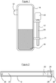
- FIG. 1 shows a prior art detector assembly for a level gauge.
- the detector assembly comprises a top housing 10, containing the control and data-processing electronics and also the power source; and an elongate housing 12 containing a plastic scintillation detector 20 arranged along the housing.
- the detectors are mounted on a circuit board.
- the detector assembly is shown mounted on a vessel 14 containing a fluid 16, by means of brackets 21, opposite a radiation source 18.
- FIG. 2 shows a section through an example detector assembly suitable for use in a radiation detector apparatus according to the invention but not as such an embodiment of the invention.
- the detector 20 is a square-section elongate plastic scintillation detector material which is coupled to a photomultiplier (PM) tube 22. Close engagement between the PM tube and the scintillator is assured by springs 30 and 28, which also allow for some thermal expansion and contraction of the components and or housing.
- the electronic components 24 include one or more microprocessors for signal processing, data processing and control functions and also a low power high voltage power source which is capable of powering the PM tube. All of the components are housed within a housing 12 which has a circular cross-section and essentially uniform diameter. The housing is closed with a suitable lid 32.
- FIG 3 shows a section through a radiation detector 25 comprising a composite detector assembly according to the invention.
- Cylindrical housing 12 contains two individual detector assemblies, 34a and 34b, each comprising a scintillator, PM tube, microprocessors and power source as described in relation to Fig 2 .
- the detector assemblies are arranged within the housing so that their scintillators extend from the respective PM tubes towards each other.
- the housing 12 is closed by lid 32.
- Fig 4 is a transverse cross-section through line A---A of Figure 3 showing how the square35 section scintillator material 12 fits into the circular section housing with space for cables 36 to be run alongside the scintillator.
- Plastic moulded packing 38 holds the contents in place and protects the scintillator and other components.
- FIG. 5 shows a level gauge incorporating a radiation detector 25 according to the invention.
- the radiation detector is mounted on vessel 14, by means of brackets 21, opposite a radiation source 18.
- the detector comprises a housing 12 containing two detector assemblies, arranged so that scintillator 20a of the first detector assembly is adjacent the electronic components 24b of the second detector assembly.
Landscapes
- Physics & Mathematics (AREA)
- Electromagnetism (AREA)
- Thermal Sciences (AREA)
- Fluid Mechanics (AREA)
- General Physics & Mathematics (AREA)
- Measurement Of Radiation (AREA)
Claims (10)
- Strahlungsdetektorvorrichtung (25), die zur Verwendung in einer Füllstandmessvorrichtung geeignet ist und ein längliches, strahlungsdurchlässiges Gehäuse (12), das eine Querschnittsfläche aufweist, die entlang der Länge des Gehäuses im Wesentlichen gleichmäßig ist, und zwei oder mehr Detektoranordnungen (34) umfasst, von denen jede Folgendes umfasst:a) mindestens einen Szintillationsdetektor (20) zum Detektieren von Strahlung;b) eine elektronische Vorrichtung (24) zum Steuern des mindestens einen Detektors und zum Verarbeiten der elektronischen Signale, die durch den mindestens einen Detektor erzeugt werden; undc) einen Fotodetektor (22);wobei die Detektoranordnungen in dem Gehäuse enthalten sind, wobei das Gehäuse einen kreisrunden Querschnitt aufweist und die Szintillationsdetektoren einen quadratischen Querschnitt aufweisen, und eine größte Abmessung aufweist, die so bemessen ist, dass der Szintillationsdetektor ins Innere des Gehäuses mit dem kreisrunden Querschnitt passt, wobei mindestens ein Kabel, das in der Lage ist, elektrische Signale und Strom zu und von mindestens einer der Detektoranordnungen zu transportieren, zwischen mindestens einem der Szintillationsdetektoren und dem Gehäuse entlang mindestens eines Abschnitts der Länge des Szintillationsdetektors verläuft.
- Strahlungsdetektorvorrichtung nach Anspruch 1, wobei die Detektoranordnung eine elektronische Vorrichtung umfasst, die eine Leistungsaufnahme von weniger als 2 W aufweist.
- Strahlungsdetektorvorrichtung nach Anspruch 1 oder Anspruch 2, wobei der Szintillationsdetektor ein Kunststoffmaterial umfasst.
- Strahlungsdetektorvorrichtung nach einem der vorangehenden Ansprüche, wobei die mindestens zwei Detektoranordnungen im Wesentlichen koaxial angeordnet sind.
- Strahlungsdetektorvorrichtung nach einem der vorangehenden Ansprüche, wobei die mindestens zwei Detektoranordnungen (34a, 34b) in Reihe angeordnet sind.
- Strahlungsdetektorvorrichtung nach einem der vorangehenden Ansprüche, wobei zwei benachbarte Detektoranordnungen so angeordnet sind, dass ihre elektronischen Vorrichtungen nebeneinander liegen.
- Strahlungsdetektorvorrichtung nach einem der Ansprüche 1-5, wobei zwei benachbarte Detektoranordnungen so angeordnet sind, dass ihre Szintillationsdetektoren nebeneinander liegen.
- Strahlungsdetektorvorrichtung nach einem der Ansprüche 1-5, wobei zwei benachbarte Detektoranordnungen so angeordnet sind, dass sich die elektronische Vorrichtung einer einzelnen Detektoranordnung neben dem Szintillationsdetektor einer anderen Detektoranordnung befindet.
- Füllstandmessvorrichtung, die eine Strahlungsdetektorvorrichtung (25) nach einem der vorangehenden Ansprüche und eine Quelle von durchdringender Strahlung (18) umfasst, die durch die Strahlungsdetektorvorrichtung detektiert werden kann, wobei die Quelle und die Strahlungsdetektorvorrichtung an oder in einem Behältnis (14) an einer Position montiert sind, die voneinander in einer solchen Weise beabstandet ist, dass von der Quelle ausgesendete Strahlung durch mindestens einen Abschnitt des Behältnisses verläuft, wo ein Füllstand eines Materials (16) zu messen ist und durch die Strahlungsdetektorvorrichtung detektiert werden kann.
- Füllstandmessvorrichtung nach Anspruch 9, wobei die Quelle eine Quelle von Gammastrahlung ist.
Applications Claiming Priority (1)
| Application Number | Priority Date | Filing Date | Title |
|---|---|---|---|
| GB0914583A GB0914583D0 (en) | 2009-08-20 | 2009-08-20 | Level measurement apparatus |
Publications (2)
| Publication Number | Publication Date |
|---|---|
| EP2314992A1 EP2314992A1 (de) | 2011-04-27 |
| EP2314992B1 true EP2314992B1 (de) | 2018-12-19 |
Family
ID=41171683
Family Applications (1)
| Application Number | Title | Priority Date | Filing Date |
|---|---|---|---|
| EP10275086.6A Active EP2314992B1 (de) | 2009-08-20 | 2010-08-17 | Füllstandsmessgerät |
Country Status (4)
| Country | Link |
|---|---|
| US (1) | US9127977B2 (de) |
| EP (1) | EP2314992B1 (de) |
| ES (1) | ES2716500T3 (de) |
| GB (1) | GB0914583D0 (de) |
Families Citing this family (8)
| Publication number | Priority date | Publication date | Assignee | Title |
|---|---|---|---|---|
| EP2465877A1 (de) * | 2010-12-20 | 2012-06-20 | Ineos Commercial Services UK Limited | Verfahren |
| EP2634542B1 (de) * | 2012-03-02 | 2019-05-15 | VEGA Grieshaber KG | Füllstandmessgerät mit Kühlkompresse, Verwendung einer Kühlkompresse, und Verfahren zum Temperieren eines Detektors mittels einer Kühlkompresse |
| GB201215920D0 (en) * | 2012-09-06 | 2012-10-24 | Johnson Matthey Plc | Radiation detector |
| GB201215919D0 (en) * | 2012-09-06 | 2012-10-24 | Johnson Matthey Plc | Radiation detector |
| DE102013225509B4 (de) * | 2013-12-10 | 2015-09-10 | Vega Grieshaber Kg | Radiometrische Dichteprofil-Messanordnung |
| EP3250868B1 (de) * | 2015-01-28 | 2020-07-15 | IMA Life North America Inc. | Prozessüberwachung und steuerung mit batterieloser mehrpunkt-drahtlosproduktzustandserfassung |
| DE102015101705B4 (de) * | 2015-02-06 | 2023-04-27 | Endress+Hauser SE+Co. KG | Messanordnung zur radiometrischen Dichte- oder Füllstandsmessung eines Mediums in einem explosionsgefährdeten Bereich |
| DE102016105385A1 (de) | 2016-03-22 | 2017-09-28 | Vega Grieshaber Kg | Sensorgehäuse und Sensor mit Sensorgehäuse |
Citations (1)
| Publication number | Priority date | Publication date | Assignee | Title |
|---|---|---|---|---|
| WO2002101415A1 (en) * | 2001-06-06 | 2002-12-19 | Reuter-Stokes, Inc. | Flexible dynamic housing |
Family Cites Families (20)
| Publication number | Priority date | Publication date | Assignee | Title |
|---|---|---|---|---|
| NL67484C (de) | 1945-01-27 | |||
| US3062957A (en) * | 1950-12-14 | 1962-11-06 | Well Surveys Inc | Scintillation counter for neutrons and gamma rays |
| US2857522A (en) * | 1951-06-16 | 1958-10-21 | California Research Corp | Radioactive bore hole logging |
| US2933601A (en) * | 1954-12-16 | 1960-04-19 | J J Maguire | Elongated liquid level gauge |
| US3654458A (en) | 1969-01-06 | 1972-04-04 | Combustion Eng | Means for detection and control of liquid level in a vessel |
| US4296321A (en) * | 1980-05-05 | 1981-10-20 | Tyco Laboratories | Bit pressure gauge for well drilling |
| DE3328256C2 (de) * | 1983-08-04 | 1986-08-28 | Endress U. Hauser Gmbh U. Co, 7867 Maulburg | Verfahren und Anordnung zur automatischen Stabilisierung eines Szintillationsdetektors |
| US4698748A (en) * | 1983-10-07 | 1987-10-06 | Essex Group, Inc. | Power-conserving control system for turning-off the power and the clocking for data transactions upon certain system inactivity |
| US4638159A (en) * | 1985-03-27 | 1987-01-20 | Halliburton Company | Graded shaped spatial resolution nuclear detectors |
| SE9703360D0 (sv) | 1997-09-17 | 1997-09-17 | Btg Kaelle Inventing Ab | Sätt och anordning för bestämning av nivån för en vätska i en behållande |
| US6222192B1 (en) | 1998-07-06 | 2001-04-24 | Saint-Gobain Industrial Ceramics, Inc. | Scintillation detector without optical window |
| DE10043629A1 (de) * | 2000-09-01 | 2002-03-14 | Endress Hauser Gmbh Co | Vorrichtung zur Bestimmung und/oder Überwachung der Dichte und/oder des Füllstands eines Füllguts in einem Behälter |
| DE10104165A1 (de) * | 2001-01-30 | 2002-09-26 | Endress & Hauser Gmbh & Co Kg | Verfahren zur Bestimmung und Darstellung einer optimirten Anordnung und Montage eines radiomatrischen Mesystem |
| DE20103881U1 (de) * | 2001-03-06 | 2001-06-13 | Berthold Technologies GmbH & Co KG, 75323 Bad Wildbad | Vorrichtung zum Messen von ionisierender Strahlung |
| US6639210B2 (en) * | 2001-03-14 | 2003-10-28 | Computalog U.S.A., Inc. | Geometrically optimized fast neutron detector |
| US7132662B2 (en) | 2003-03-28 | 2006-11-07 | Ronan Engineering Company | Flexible liquid-filled radiation detector scintillator |
| DE102006048266A1 (de) * | 2006-10-12 | 2008-04-17 | Berthold Technologies Gmbh & Co. Kg | Vorrichtung zum Messen ionisierender Strahlung |
| DE102007048203A1 (de) * | 2007-10-08 | 2009-04-09 | Vega Grieshaber Kg | Füllstandmessgerät mit explosionssicherem Gehäuse |
| CN201096508Y (zh) | 2007-11-02 | 2008-08-06 | 黑龙江省中贝技术有限公司 | 用于物位检测的闪烁探测器 |
| DE102007053860A1 (de) * | 2007-11-09 | 2009-05-14 | Endress + Hauser Gmbh + Co. Kg | Radiometrisches Messgerät |
-
2009
- 2009-08-20 GB GB0914583A patent/GB0914583D0/en not_active Ceased
-
2010
- 2010-08-17 ES ES10275086T patent/ES2716500T3/es active Active
- 2010-08-17 EP EP10275086.6A patent/EP2314992B1/de active Active
- 2010-08-20 US US12/860,546 patent/US9127977B2/en active Active
Patent Citations (1)
| Publication number | Priority date | Publication date | Assignee | Title |
|---|---|---|---|---|
| WO2002101415A1 (en) * | 2001-06-06 | 2002-12-19 | Reuter-Stokes, Inc. | Flexible dynamic housing |
Also Published As
| Publication number | Publication date |
|---|---|
| GB0914583D0 (en) | 2009-09-30 |
| EP2314992A1 (de) | 2011-04-27 |
| ES2716500T3 (es) | 2019-06-12 |
| US20110044427A1 (en) | 2011-02-24 |
| US9127977B2 (en) | 2015-09-08 |
Similar Documents
| Publication | Publication Date | Title |
|---|---|---|
| US9127977B2 (en) | Level measurement apparatus | |
| EP2329234B1 (de) | Füllstandsmesssystem | |
| US9625591B2 (en) | Radiation detector probe for ionising radiation | |
| US20120043466A1 (en) | Radiometric Measuring Device | |
| CA2840661C (en) | Level measurement method and apparatus | |
| CN104603584B (zh) | 用于密度或水平面测量的辐射检测器 | |
| CN104755888B (zh) | 辐射检测器 | |
| US9715022B2 (en) | Scintillation detector package having radioactive support apparatus | |
| US7132662B2 (en) | Flexible liquid-filled radiation detector scintillator | |
| JP6034141B2 (ja) | 放射線検出器 | |
| LIPTÁK et al. | 3.15 Radiation Level Sensors | |
| Le Viet et al. | Development of compact gamma-ray sensor with CDS photoresistor |
Legal Events
| Date | Code | Title | Description |
|---|---|---|---|
| PUAI | Public reference made under article 153(3) epc to a published international application that has entered the european phase |
Free format text: ORIGINAL CODE: 0009012 |
|
| AK | Designated contracting states |
Kind code of ref document: A1 Designated state(s): AL AT BE BG CH CY CZ DE DK EE ES FI FR GB GR HR HU IE IS IT LI LT LU LV MC MK MT NL NO PL PT RO SE SI SK SM TR |
|
| AX | Request for extension of the european patent |
Extension state: BA ME RS |
|
| 17P | Request for examination filed |
Effective date: 20111027 |
|
| STAA | Information on the status of an ep patent application or granted ep patent |
Free format text: STATUS: EXAMINATION IS IN PROGRESS |
|
| 17Q | First examination report despatched |
Effective date: 20170322 |
|
| GRAP | Despatch of communication of intention to grant a patent |
Free format text: ORIGINAL CODE: EPIDOSNIGR1 |
|
| STAA | Information on the status of an ep patent application or granted ep patent |
Free format text: STATUS: GRANT OF PATENT IS INTENDED |
|
| RIC1 | Information provided on ipc code assigned before grant |
Ipc: G01T 1/203 20060101ALI20180608BHEP Ipc: G01F 23/288 20060101AFI20180608BHEP |
|
| INTG | Intention to grant announced |
Effective date: 20180628 |
|
| GRAS | Grant fee paid |
Free format text: ORIGINAL CODE: EPIDOSNIGR3 |
|
| GRAA | (expected) grant |
Free format text: ORIGINAL CODE: 0009210 |
|
| STAA | Information on the status of an ep patent application or granted ep patent |
Free format text: STATUS: THE PATENT HAS BEEN GRANTED |
|
| AK | Designated contracting states |
Kind code of ref document: B1 Designated state(s): AL AT BE BG CH CY CZ DE DK EE ES FI FR GB GR HR HU IE IS IT LI LT LU LV MC MK MT NL NO PL PT RO SE SI SK SM TR |
|
| REG | Reference to a national code |
Ref country code: GB Ref legal event code: FG4D |
|
| REG | Reference to a national code |
Ref country code: CH Ref legal event code: EP |
|
| REG | Reference to a national code |
Ref country code: IE Ref legal event code: FG4D |
|
| REG | Reference to a national code |
Ref country code: DE Ref legal event code: R096 Ref document number: 602010055883 Country of ref document: DE |
|
| REG | Reference to a national code |
Ref country code: AT Ref legal event code: REF Ref document number: 1079222 Country of ref document: AT Kind code of ref document: T Effective date: 20190115 |
|
| REG | Reference to a national code |
Ref country code: NL Ref legal event code: FP |
|
| PG25 | Lapsed in a contracting state [announced via postgrant information from national office to epo] |
Ref country code: LT Free format text: LAPSE BECAUSE OF FAILURE TO SUBMIT A TRANSLATION OF THE DESCRIPTION OR TO PAY THE FEE WITHIN THE PRESCRIBED TIME-LIMIT Effective date: 20181219 Ref country code: HR Free format text: LAPSE BECAUSE OF FAILURE TO SUBMIT A TRANSLATION OF THE DESCRIPTION OR TO PAY THE FEE WITHIN THE PRESCRIBED TIME-LIMIT Effective date: 20181219 Ref country code: LV Free format text: LAPSE BECAUSE OF FAILURE TO SUBMIT A TRANSLATION OF THE DESCRIPTION OR TO PAY THE FEE WITHIN THE PRESCRIBED TIME-LIMIT Effective date: 20181219 Ref country code: NO Free format text: LAPSE BECAUSE OF FAILURE TO SUBMIT A TRANSLATION OF THE DESCRIPTION OR TO PAY THE FEE WITHIN THE PRESCRIBED TIME-LIMIT Effective date: 20190319 Ref country code: FI Free format text: LAPSE BECAUSE OF FAILURE TO SUBMIT A TRANSLATION OF THE DESCRIPTION OR TO PAY THE FEE WITHIN THE PRESCRIBED TIME-LIMIT Effective date: 20181219 Ref country code: BG Free format text: LAPSE BECAUSE OF FAILURE TO SUBMIT A TRANSLATION OF THE DESCRIPTION OR TO PAY THE FEE WITHIN THE PRESCRIBED TIME-LIMIT Effective date: 20190319 |
|
| REG | Reference to a national code |
Ref country code: LT Ref legal event code: MG4D |
|
| REG | Reference to a national code |
Ref country code: AT Ref legal event code: MK05 Ref document number: 1079222 Country of ref document: AT Kind code of ref document: T Effective date: 20181219 |
|
| PG25 | Lapsed in a contracting state [announced via postgrant information from national office to epo] |
Ref country code: GR Free format text: LAPSE BECAUSE OF FAILURE TO SUBMIT A TRANSLATION OF THE DESCRIPTION OR TO PAY THE FEE WITHIN THE PRESCRIBED TIME-LIMIT Effective date: 20190320 Ref country code: AL Free format text: LAPSE BECAUSE OF FAILURE TO SUBMIT A TRANSLATION OF THE DESCRIPTION OR TO PAY THE FEE WITHIN THE PRESCRIBED TIME-LIMIT Effective date: 20181219 Ref country code: SE Free format text: LAPSE BECAUSE OF FAILURE TO SUBMIT A TRANSLATION OF THE DESCRIPTION OR TO PAY THE FEE WITHIN THE PRESCRIBED TIME-LIMIT Effective date: 20181219 |
|
| REG | Reference to a national code |
Ref country code: ES Ref legal event code: FG2A Ref document number: 2716500 Country of ref document: ES Kind code of ref document: T3 Effective date: 20190612 |
|
| PG25 | Lapsed in a contracting state [announced via postgrant information from national office to epo] |
Ref country code: PL Free format text: LAPSE BECAUSE OF FAILURE TO SUBMIT A TRANSLATION OF THE DESCRIPTION OR TO PAY THE FEE WITHIN THE PRESCRIBED TIME-LIMIT Effective date: 20181219 Ref country code: PT Free format text: LAPSE BECAUSE OF FAILURE TO SUBMIT A TRANSLATION OF THE DESCRIPTION OR TO PAY THE FEE WITHIN THE PRESCRIBED TIME-LIMIT Effective date: 20190419 Ref country code: CZ Free format text: LAPSE BECAUSE OF FAILURE TO SUBMIT A TRANSLATION OF THE DESCRIPTION OR TO PAY THE FEE WITHIN THE PRESCRIBED TIME-LIMIT Effective date: 20181219 |
|
| PG25 | Lapsed in a contracting state [announced via postgrant information from national office to epo] |
Ref country code: SM Free format text: LAPSE BECAUSE OF FAILURE TO SUBMIT A TRANSLATION OF THE DESCRIPTION OR TO PAY THE FEE WITHIN THE PRESCRIBED TIME-LIMIT Effective date: 20181219 Ref country code: EE Free format text: LAPSE BECAUSE OF FAILURE TO SUBMIT A TRANSLATION OF THE DESCRIPTION OR TO PAY THE FEE WITHIN THE PRESCRIBED TIME-LIMIT Effective date: 20181219 Ref country code: SK Free format text: LAPSE BECAUSE OF FAILURE TO SUBMIT A TRANSLATION OF THE DESCRIPTION OR TO PAY THE FEE WITHIN THE PRESCRIBED TIME-LIMIT Effective date: 20181219 Ref country code: IS Free format text: LAPSE BECAUSE OF FAILURE TO SUBMIT A TRANSLATION OF THE DESCRIPTION OR TO PAY THE FEE WITHIN THE PRESCRIBED TIME-LIMIT Effective date: 20190419 Ref country code: RO Free format text: LAPSE BECAUSE OF FAILURE TO SUBMIT A TRANSLATION OF THE DESCRIPTION OR TO PAY THE FEE WITHIN THE PRESCRIBED TIME-LIMIT Effective date: 20181219 |
|
| REG | Reference to a national code |
Ref country code: DE Ref legal event code: R097 Ref document number: 602010055883 Country of ref document: DE |
|
| REG | Reference to a national code |
Ref country code: DE Ref legal event code: R082 Ref document number: 602010055883 Country of ref document: DE Representative=s name: MURGITROYD GERMANY PATENTANWALTSGESELLSCHAFT M, DE Ref country code: DE Ref legal event code: R082 Ref document number: 602010055883 Country of ref document: DE Representative=s name: BARDEHLE PAGENBERG PARTNERSCHAFT MBB PATENTANW, DE |
|
| PLBE | No opposition filed within time limit |
Free format text: ORIGINAL CODE: 0009261 |
|
| STAA | Information on the status of an ep patent application or granted ep patent |
Free format text: STATUS: NO OPPOSITION FILED WITHIN TIME LIMIT |
|
| PG25 | Lapsed in a contracting state [announced via postgrant information from national office to epo] |
Ref country code: DK Free format text: LAPSE BECAUSE OF FAILURE TO SUBMIT A TRANSLATION OF THE DESCRIPTION OR TO PAY THE FEE WITHIN THE PRESCRIBED TIME-LIMIT Effective date: 20181219 Ref country code: AT Free format text: LAPSE BECAUSE OF FAILURE TO SUBMIT A TRANSLATION OF THE DESCRIPTION OR TO PAY THE FEE WITHIN THE PRESCRIBED TIME-LIMIT Effective date: 20181219 |
|
| 26N | No opposition filed |
Effective date: 20190920 |
|
| PG25 | Lapsed in a contracting state [announced via postgrant information from national office to epo] |
Ref country code: SI Free format text: LAPSE BECAUSE OF FAILURE TO SUBMIT A TRANSLATION OF THE DESCRIPTION OR TO PAY THE FEE WITHIN THE PRESCRIBED TIME-LIMIT Effective date: 20181219 |
|
| PG25 | Lapsed in a contracting state [announced via postgrant information from national office to epo] |
Ref country code: TR Free format text: LAPSE BECAUSE OF FAILURE TO SUBMIT A TRANSLATION OF THE DESCRIPTION OR TO PAY THE FEE WITHIN THE PRESCRIBED TIME-LIMIT Effective date: 20181219 |
|
| PG25 | Lapsed in a contracting state [announced via postgrant information from national office to epo] |
Ref country code: CH Free format text: LAPSE BECAUSE OF NON-PAYMENT OF DUE FEES Effective date: 20190831 Ref country code: LU Free format text: LAPSE BECAUSE OF NON-PAYMENT OF DUE FEES Effective date: 20190817 Ref country code: LI Free format text: LAPSE BECAUSE OF NON-PAYMENT OF DUE FEES Effective date: 20190831 Ref country code: MC Free format text: LAPSE BECAUSE OF FAILURE TO SUBMIT A TRANSLATION OF THE DESCRIPTION OR TO PAY THE FEE WITHIN THE PRESCRIBED TIME-LIMIT Effective date: 20181219 |
|
| REG | Reference to a national code |
Ref country code: BE Ref legal event code: MM Effective date: 20190831 |
|
| PG25 | Lapsed in a contracting state [announced via postgrant information from national office to epo] |
Ref country code: IE Free format text: LAPSE BECAUSE OF NON-PAYMENT OF DUE FEES Effective date: 20190817 Ref country code: FR Free format text: LAPSE BECAUSE OF NON-PAYMENT OF DUE FEES Effective date: 20190831 |
|
| PG25 | Lapsed in a contracting state [announced via postgrant information from national office to epo] |
Ref country code: BE Free format text: LAPSE BECAUSE OF NON-PAYMENT OF DUE FEES Effective date: 20190831 |
|
| PG25 | Lapsed in a contracting state [announced via postgrant information from national office to epo] |
Ref country code: CY Free format text: LAPSE BECAUSE OF FAILURE TO SUBMIT A TRANSLATION OF THE DESCRIPTION OR TO PAY THE FEE WITHIN THE PRESCRIBED TIME-LIMIT Effective date: 20181219 |
|
| PG25 | Lapsed in a contracting state [announced via postgrant information from national office to epo] |
Ref country code: HU Free format text: LAPSE BECAUSE OF FAILURE TO SUBMIT A TRANSLATION OF THE DESCRIPTION OR TO PAY THE FEE WITHIN THE PRESCRIBED TIME-LIMIT; INVALID AB INITIO Effective date: 20100817 Ref country code: MT Free format text: LAPSE BECAUSE OF FAILURE TO SUBMIT A TRANSLATION OF THE DESCRIPTION OR TO PAY THE FEE WITHIN THE PRESCRIBED TIME-LIMIT Effective date: 20181219 |
|
| PG25 | Lapsed in a contracting state [announced via postgrant information from national office to epo] |
Ref country code: MK Free format text: LAPSE BECAUSE OF FAILURE TO SUBMIT A TRANSLATION OF THE DESCRIPTION OR TO PAY THE FEE WITHIN THE PRESCRIBED TIME-LIMIT Effective date: 20181219 |
|
| P01 | Opt-out of the competence of the unified patent court (upc) registered |
Effective date: 20230526 |
|
| REG | Reference to a national code |
Ref country code: DE Ref legal event code: R082 Ref document number: 602010055883 Country of ref document: DE Representative=s name: MURGITROYD GERMANY PATENTANWALTSGESELLSCHAFT M, DE |
|
| REG | Reference to a national code |
Ref country code: DE Ref legal event code: R081 Ref document number: 602010055883 Country of ref document: DE Owner name: TRACERCO LTD., GB Free format text: FORMER OWNER: JOHNSON MATTHEY PLC, LONDON, GB |
|
| REG | Reference to a national code |
Ref country code: GB Ref legal event code: 732E Free format text: REGISTERED BETWEEN 20240229 AND 20240306 |
|
| REG | Reference to a national code |
Ref country code: NL Ref legal event code: PD Owner name: TRACERCO LIMITED; GB Free format text: DETAILS ASSIGNMENT: CHANGE OF OWNER(S), ASSIGNMENT; FORMER OWNER NAME: JOHNSON MATTHEY PLC Effective date: 20240425 |
|
| REG | Reference to a national code |
Ref country code: ES Ref legal event code: PC2A Owner name: TRACERCO LIMITED Effective date: 20240916 |
|
| PGFP | Annual fee paid to national office [announced via postgrant information from national office to epo] |
Ref country code: ES Payment date: 20250901 Year of fee payment: 16 |
|
| PGFP | Annual fee paid to national office [announced via postgrant information from national office to epo] |
Ref country code: NL Payment date: 20260212 Year of fee payment: 16 |
|
| PGFP | Annual fee paid to national office [announced via postgrant information from national office to epo] |
Ref country code: GB Payment date: 20260130 Year of fee payment: 16 |
|
| PGFP | Annual fee paid to national office [announced via postgrant information from national office to epo] |
Ref country code: DE Payment date: 20260130 Year of fee payment: 16 |
|
| PGFP | Annual fee paid to national office [announced via postgrant information from national office to epo] |
Ref country code: IT Payment date: 20260203 Year of fee payment: 16 |