EP2314920A2 - Retrofit method for pulverized coal boiler - Google Patents
Retrofit method for pulverized coal boiler Download PDFInfo
- Publication number
- EP2314920A2 EP2314920A2 EP10188539A EP10188539A EP2314920A2 EP 2314920 A2 EP2314920 A2 EP 2314920A2 EP 10188539 A EP10188539 A EP 10188539A EP 10188539 A EP10188539 A EP 10188539A EP 2314920 A2 EP2314920 A2 EP 2314920A2
- Authority
- EP
- European Patent Office
- Prior art keywords
- pulverized coal
- furnace
- burners
- coal boiler
- air
- Prior art date
- Legal status (The legal status is an assumption and is not a legal conclusion. Google has not performed a legal analysis and makes no representation as to the accuracy of the status listed.)
- Granted
Links
- 239000003245 coal Substances 0.000 title claims abstract description 206
- 238000000034 method Methods 0.000 title claims abstract description 43
- 238000002485 combustion reaction Methods 0.000 claims abstract description 155
- 239000007789 gas Substances 0.000 claims abstract description 150
- QVGXLLKOCUKJST-UHFFFAOYSA-N atomic oxygen Chemical compound [O] QVGXLLKOCUKJST-UHFFFAOYSA-N 0.000 claims abstract description 51
- 239000001301 oxygen Substances 0.000 claims abstract description 51
- 229910052760 oxygen Inorganic materials 0.000 claims abstract description 51
- 238000009420 retrofitting Methods 0.000 claims abstract description 37
- 239000000446 fuel Substances 0.000 claims abstract description 15
- 238000000926 separation method Methods 0.000 claims abstract description 15
- 238000011084 recovery Methods 0.000 claims abstract description 10
- 238000010521 absorption reaction Methods 0.000 description 8
- 239000000463 material Substances 0.000 description 6
- 238000010586 diagram Methods 0.000 description 5
- 238000009434 installation Methods 0.000 description 5
- 238000007664 blowing Methods 0.000 description 3
- XLYOFNOQVPJJNP-UHFFFAOYSA-N water Substances O XLYOFNOQVPJJNP-UHFFFAOYSA-N 0.000 description 3
- 230000005540 biological transmission Effects 0.000 description 2
- 239000000203 mixture Substances 0.000 description 2
- MYMOFIZGZYHOMD-UHFFFAOYSA-N Dioxygen Chemical compound O=O MYMOFIZGZYHOMD-UHFFFAOYSA-N 0.000 description 1
- 238000009841 combustion method Methods 0.000 description 1
- 238000009833 condensation Methods 0.000 description 1
- 230000005494 condensation Effects 0.000 description 1
- 238000001816 cooling Methods 0.000 description 1
- 238000012217 deletion Methods 0.000 description 1
- 230000037430 deletion Effects 0.000 description 1
- 230000000694 effects Effects 0.000 description 1
- 239000007769 metal material Substances 0.000 description 1
- 239000007800 oxidant agent Substances 0.000 description 1
- 238000010298 pulverizing process Methods 0.000 description 1
- 238000007670 refining Methods 0.000 description 1
- 238000010792 warming Methods 0.000 description 1
Images


Classifications
-
- F—MECHANICAL ENGINEERING; LIGHTING; HEATING; WEAPONS; BLASTING
- F23—COMBUSTION APPARATUS; COMBUSTION PROCESSES
- F23L—SUPPLYING AIR OR NON-COMBUSTIBLE LIQUIDS OR GASES TO COMBUSTION APPARATUS IN GENERAL ; VALVES OR DAMPERS SPECIALLY ADAPTED FOR CONTROLLING AIR SUPPLY OR DRAUGHT IN COMBUSTION APPARATUS; INDUCING DRAUGHT IN COMBUSTION APPARATUS; TOPS FOR CHIMNEYS OR VENTILATING SHAFTS; TERMINALS FOR FLUES
- F23L7/00—Supplying non-combustible liquids or gases, other than air, to the fire, e.g. oxygen, steam
- F23L7/007—Supplying oxygen or oxygen-enriched air
-
- F—MECHANICAL ENGINEERING; LIGHTING; HEATING; WEAPONS; BLASTING
- F23—COMBUSTION APPARATUS; COMBUSTION PROCESSES
- F23C—METHODS OR APPARATUS FOR COMBUSTION USING FLUID FUEL OR SOLID FUEL SUSPENDED IN A CARRIER GAS OR AIR
- F23C9/00—Combustion apparatus characterised by arrangements for returning combustion products or flue gases to the combustion chamber
- F23C9/003—Combustion apparatus characterised by arrangements for returning combustion products or flue gases to the combustion chamber for pulverulent fuel
-
- F—MECHANICAL ENGINEERING; LIGHTING; HEATING; WEAPONS; BLASTING
- F23—COMBUSTION APPARATUS; COMBUSTION PROCESSES
- F23C—METHODS OR APPARATUS FOR COMBUSTION USING FLUID FUEL OR SOLID FUEL SUSPENDED IN A CARRIER GAS OR AIR
- F23C2202/00—Fluegas recirculation
- F23C2202/30—Premixing fluegas with combustion air
-
- F—MECHANICAL ENGINEERING; LIGHTING; HEATING; WEAPONS; BLASTING
- F23—COMBUSTION APPARATUS; COMBUSTION PROCESSES
- F23L—SUPPLYING AIR OR NON-COMBUSTIBLE LIQUIDS OR GASES TO COMBUSTION APPARATUS IN GENERAL ; VALVES OR DAMPERS SPECIALLY ADAPTED FOR CONTROLLING AIR SUPPLY OR DRAUGHT IN COMBUSTION APPARATUS; INDUCING DRAUGHT IN COMBUSTION APPARATUS; TOPS FOR CHIMNEYS OR VENTILATING SHAFTS; TERMINALS FOR FLUES
- F23L2900/00—Special arrangements for supplying or treating air or oxidant for combustion; Injecting inert gas, water or steam into the combustion chamber
- F23L2900/07001—Injecting synthetic air, i.e. a combustion supporting mixture made of pure oxygen and an inert gas, e.g. nitrogen or recycled fumes
-
- Y—GENERAL TAGGING OF NEW TECHNOLOGICAL DEVELOPMENTS; GENERAL TAGGING OF CROSS-SECTIONAL TECHNOLOGIES SPANNING OVER SEVERAL SECTIONS OF THE IPC; TECHNICAL SUBJECTS COVERED BY FORMER USPC CROSS-REFERENCE ART COLLECTIONS [XRACs] AND DIGESTS
- Y02—TECHNOLOGIES OR APPLICATIONS FOR MITIGATION OR ADAPTATION AGAINST CLIMATE CHANGE
- Y02E—REDUCTION OF GREENHOUSE GAS [GHG] EMISSIONS, RELATED TO ENERGY GENERATION, TRANSMISSION OR DISTRIBUTION
- Y02E20/00—Combustion technologies with mitigation potential
- Y02E20/32—Direct CO2 mitigation
-
- Y—GENERAL TAGGING OF NEW TECHNOLOGICAL DEVELOPMENTS; GENERAL TAGGING OF CROSS-SECTIONAL TECHNOLOGIES SPANNING OVER SEVERAL SECTIONS OF THE IPC; TECHNICAL SUBJECTS COVERED BY FORMER USPC CROSS-REFERENCE ART COLLECTIONS [XRACs] AND DIGESTS
- Y02—TECHNOLOGIES OR APPLICATIONS FOR MITIGATION OR ADAPTATION AGAINST CLIMATE CHANGE
- Y02E—REDUCTION OF GREENHOUSE GAS [GHG] EMISSIONS, RELATED TO ENERGY GENERATION, TRANSMISSION OR DISTRIBUTION
- Y02E20/00—Combustion technologies with mitigation potential
- Y02E20/34—Indirect CO2mitigation, i.e. by acting on non CO2directly related matters of the process, e.g. pre-heating or heat recovery
-
- Y—GENERAL TAGGING OF NEW TECHNOLOGICAL DEVELOPMENTS; GENERAL TAGGING OF CROSS-SECTIONAL TECHNOLOGIES SPANNING OVER SEVERAL SECTIONS OF THE IPC; TECHNICAL SUBJECTS COVERED BY FORMER USPC CROSS-REFERENCE ART COLLECTIONS [XRACs] AND DIGESTS
- Y10—TECHNICAL SUBJECTS COVERED BY FORMER USPC
- Y10T—TECHNICAL SUBJECTS COVERED BY FORMER US CLASSIFICATION
- Y10T29/00—Metal working
- Y10T29/49—Method of mechanical manufacture
- Y10T29/4935—Heat exchanger or boiler making
- Y10T29/49352—Repairing, converting, servicing or salvaging
-
- Y—GENERAL TAGGING OF NEW TECHNOLOGICAL DEVELOPMENTS; GENERAL TAGGING OF CROSS-SECTIONAL TECHNOLOGIES SPANNING OVER SEVERAL SECTIONS OF THE IPC; TECHNICAL SUBJECTS COVERED BY FORMER USPC CROSS-REFERENCE ART COLLECTIONS [XRACs] AND DIGESTS
- Y10—TECHNICAL SUBJECTS COVERED BY FORMER USPC
- Y10T—TECHNICAL SUBJECTS COVERED BY FORMER US CLASSIFICATION
- Y10T29/00—Metal working
- Y10T29/49—Method of mechanical manufacture
- Y10T29/4935—Heat exchanger or boiler making
- Y10T29/49387—Boiler making
-
- Y—GENERAL TAGGING OF NEW TECHNOLOGICAL DEVELOPMENTS; GENERAL TAGGING OF CROSS-SECTIONAL TECHNOLOGIES SPANNING OVER SEVERAL SECTIONS OF THE IPC; TECHNICAL SUBJECTS COVERED BY FORMER USPC CROSS-REFERENCE ART COLLECTIONS [XRACs] AND DIGESTS
- Y10—TECHNICAL SUBJECTS COVERED BY FORMER USPC
- Y10T—TECHNICAL SUBJECTS COVERED BY FORMER US CLASSIFICATION
- Y10T29/00—Metal working
- Y10T29/49—Method of mechanical manufacture
- Y10T29/49716—Converting
Definitions
- the present invention relates to a method for retrofitting a pulverized coal boiler in which a pulverized coal boiler in an air combustion boiler system is retrofitted into a pulverized coal boiler in an oxyfuel combustion boiler system.
- the exhaust gas Since the majority of exhaust gas will be CO 2 in oxyfuel combustion, the exhaust gas does not require condensation for recovering CO 2 .
- the exhaust gas can be directly compressed and cooled to separate CO 2 for liquefaction. This is one of the effective ways to reduce CO 2 emissions.
- Japanese Patent application Laid-open No. 2001-201406 discloses a retrofit method for a pulverized coal boiler in an air combustion system. This discloses a technique in which an after-air port is installed obliquely upward at a position below the tip of the flame produced by a burner in a furnace, thereby allowing adjustments of the combustion load in the furnace.
- This object is achieved by a method according to claim 1.
- One aspect of the invention relates to a method for retrofitting a pulverized coal boiler in an air combustion boiler system having a plurality of burners over a plurality of stages along the vertical direction on a wall surface of a furnace of the pulverized coal boiler and an after-air port for introducing air for two-stage combustion located above the burners to retrofit into a two-stage combustion pulverized coal boiler in an oxyfuel combustion boiler system, wherein an air separation unit for separating oxygen from air and a CO 2 recovery device for absorbing and separating CO 2 gas from combustion exhaust gas generated in the boiler furnace is installed, wherein the method for retrofitting the combustion pulverized coal boiler is comprising the steps of: stopping to supply fuel into the furnace from a burner located in a middle stage among the plurality of stages of burners installed on the wall surface of the furnace of the pulverized coal boiler; installing a new burner to an opening of the after-air port provided on the wall surface of the furnace of the pulverized coal boiler; and installing a supply line to
- a further aspect of the invention relates to a method for retrofitting a pulverized coal boiler in an air combustion boiler system having a plurality of burners over a plurality of stages along the vertical direction on a wall surface of a furnace of the pulverized coal boiler, a main after-air port and a sub-after-air port located in the lower stage of the main after-air port for introducing air for two-stage combustion located above the burners to retrofit into a two-stage combustion pulverized coal boiler in an oxyfuel combustion boiler system, wherein an air separation unit for separating oxygen from air and a CO 2 recovery device for absorbing and separating CO 2 gas from combustion exhaust gas generated in the boiler furnace is installed, wherein the method for retrofitting the combustion pulverized coal boiler is comprising the steps of: stopping to supply fuel into the furnace from a burner located in a middle stage among the plurality of stages of burners installed on the wall surface of the furnace of the pulverized coal boiler; installing another burner to an opening of the main after-air port provided
- a further aspect of the invention relates to a method for retrofitting a pulverized coal boiler in an air combustion boiler system having a plurality of burners over a plurality of stages along the vertical direction on a wall surface of a furnace of the pulverized coal boiler and an after-air port for introducing air for two-stage combustion located above the burners to retrofit into a two-stage combustion pulverized coal boiler in an oxyfuel combustion boiler system of the present invention, wherein an air separation unit for separating oxygen from air and a CO 2 recovery device for absorbing and separating CO 2 gas from combustion exhaust gas generated in the boiler furnace is installed, wherein the method for retrofitting the combustion pulverized coal boiler is comprising the steps of: stopping to supply fuel into the furnace from a burner located in a middle stage among the plurality of stages of burners installed on the wall surface of the furnace of the pulverized coal boiler; installing a new burner to an opening of the after-air port provided on the wall surface of the furnace of the pulverized coal boiler; installing
- the heat load on a furnace wall of the pulverized coal boiler can be reduced so that retrofit into the pulverized coal boiler in the oxyfuel combustion boiler system which maintains structural reliability can be achieved at low cost in a short period of time.
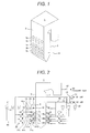
- FIG. 1 At first, the structure of a furnace of a pulverized coal boiler for the present invention will be described using FIG. 1 .
- furnace walls making up a furnace 1 include a furnace front wall 2, a furnace back wall 3 opposing the furnace front wall 2, and furnace side walls 4 which are the both side walls between the furnace front wall 2 and the furnace back wall 3; and these furnace walls surround the furnace 1 to form a furnace combustion space for burning pulverized coal fuel in the furnace 1.
- Three stages of openings (upper stage openings 5a, middle stage openings 5b, and lower stage openings 5c) for installing burners are provided in the lower portions of the furnace front wall 2 and the furnace back wall 3.
- Four openings 5a, 5b, and 5c are provided per stage, and a burner is installed to each opening.
- openings 6b for setting up sub-after-air ports are provided below the openings 6a for setting up the main after-air ports.
- the present embodiment shows the four openings 5a, 5b, and 5c for installing burners and the four openings 6a for setting up after-air ports
- the present invention has no limit to the number of openings on the pulverized coal boiler for retrofit.
- the present invention is not limited to the pulverized coal boiler for retrofitting to a two-stage after-air style boiler having a main after-air port and a sub-after-air port.
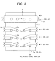
- the air combustion boiler system having the pulverized coal boiler before retrofit includes the furnace 1, and in the lower portions of the furnace front wall 2 of the furnace 1 and the furnace back wall 3 opposing the furnace front wall 2, a plurality of stages of burners are provided facing each other along the vertical direction over three stages of lower stage burners 7a, middle stage burners 7b, and the upper stage burners 7c.
- Two coal pulverizers 10 for pulverizing coal fuel into pulverized coal are each provided to the burner stages separately set up as the upper, middle, and lower stages on the furnace front wall 2 and the furnace back wall 3 of the furnace 1 (a total of six coal pulverizers in the upper, middle, and lower stages).
- Coal 12 is a fuel stored in a hopper 11, and after being pulverized in the coal pulverizer 10, the pulverized coal is transported by air 61 supplied from a blower 31 to the coal pulverizer 10 through a pulverized coal transporting air supply line 46.
- the pulverized coal is then supplied with the air 61 to each of the lower stage burners 7a, the middle stage burners 7b, and the upper stage burners 7c through coal supply pipes 41 a, 41 b, and 41 c respectively, and ejected into the furnace 1 for burning.
- air 62 supplied from a blower 32 as secondary and tertiary air for burners is supplied from a secondary and tertiary air supply line 45 for burners to the lower stage burners 7a, the middle stage burners 7b, and the upper stage burners 7c through secondary and tertiary air supply lines 40a, 40b, and 40c for burners respectively.
- after-air ports 9a are set up facing each other. These after-air ports 9a supply additional air for two-stage combustion into the furnace 1.
- the air 62 supplied from the blower 32 is supplied to each burner 7, as well as to each after-air port 9a through a windbox 8, after being preheated by an air preheater 19 which exchanges heat with exhaust gas 63 exhausted from the furnace 1 through an exhaust gas line 47.
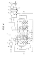
- furnace 1 of the pulverized coal boiler in the embodiment of the present invention, a partial structure of the furnace front wall of the pulverized coal boiler in the air combustion boiler system before retrofit, viewed from the furnace front wall, will be explained using FIG. 3 .
- FIG. 3 is a partial structural view of the pulverized coal boiler in the air combustion boiler system before retrofit, viewed from the furnace front wall 2.
- Four burners are installed for each stage of the upper stage burners 7c, the middle stage burners 7b, and the lower stage burners 7a in the lower portion of the furnace front wall 2.
- Pulverized coal fuel-and-air 65 is supplied through the coal supply pipes 41 a, 41 b, and 41 c from the direction orthogonal to the furnace front wall 2, and air 62a, 62b, and 62c are each supplied as secondary and tertiary air for burners to the burners 7 through the secondary and tertiary air introducing lines 40a, 40b, and 40c.
- the windbox 8 is installed on the furnace wall in the upper stage further above the installation of the upper stage burners 7c, and air 62d is supplied from the secondary and tertiary air supply line 45 for burners through an air line 42a for a windbox.
- the air 62d introduced into the windbox 8 is supplied into the furnace 1 through the after-air ports 9a.
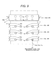
- FIG. 4 is an overall structural view in which the pulverized coal boiler in the air combustion boiler system is retrofitted into a pulverized coal boiler in the oxyfuel combustion boiler system according to the embodiment of the present invention.
- the middle stage burners 7b are stopped from supplying fuel into the furnace, in which case middle stage burners 7b are burners located in the middle stage among the upper stage burners 7c, the middle stage burners 7b, and the lower stage burners 7a disposed on the furnace front wall 2 and the furnace back wall 3 before retrofit.
- the pulverized coal boiler in the present embodiment is provided with three-stage burners having the upper stage burners 7c, the middle stage burners 7b, and the lower stage burners 7a disposed on the furnace front wall 2 and the furnace back wall 3 of the furnace 1, the burners located in the middle stage will be the middle stage burners 7b; however, when, for example, four stages of burners are disposed on the furnace front wall 2 and the furnace back wall 3, the burners located in the middle stage will be either the burners in the second stage from the bottom or those in the second stage from the top.
- New burners 7d are, then, installed to the openings 6a for installing after-air ports without creating a new opening on a wall surface of the furnace 1, extending each burner distance between the plurality of burners disposed along the vertical direction.
- an oxygen separator 17 and a gas mixer 18 are installed. Pure oxygen is made by the oxygen separator 17 having a cryogenic separation device and the like, which separates oxygen from air 65 supplied by a blower 33.
- the exhaust gas line 47 for passing down exhaust gas, which is mainly CO 2 , exhausted from the furnace 1 after pulverized coal has been burnt in the furnace 1 of the pulverized coal boiler is provided with a gas refiner 13 for refining the exhaust gas; a gas preheater 14 for exchanging heat using, as a heat source, the exhaust gas which has passed through the gas refiner 13; a cryogenic dehumidifier 15 for dehumidifying the exhaust gas which has passed through the gas preheater 14; and a CO 2 recovery device 16 for recovering CO 2 from the exhaust gas which has passed through the cryogenic dehumidifier 15 by cooling the gas.
- CO 2 in the exhaust gas is recovered as liquefied CO 2 (66) by the CO 2 recovery device 16.
- part of the exhaust gas which has passed through the cryogenic dehumidifier 15 flows through a line 48 to the gas preheater 14, and after being preheated by the gas preheater 14, it is supplied as recirculation gas to the gas mixer 18 through recirculation lines 49 and 53 by a blower 34.
- Each burner stage of the upper stage burners 7c, the lower stage burners 7a, and the burners 7d separately installed to the openings 6 for installing after-air ports on the furnace front wall 2 and the furnace back wall 3 of the furnace 1 is provided with two coal pulverizers 10 for supplying a pulverized coal fuel.
- the coal 12 is pulverized in the coal pulverizer 10, and after turning into pulverized coal, it is transported by the recirculation gas flowing through a recirculation gas line 50. Then, the pulverized coal transported by the recirculation gas is supplied along with the recirculation gas to each of the lower stage burners 7a, the upper stage burners 7c, and the burners 7d through the coal supply pipes 41 a, 41 c, and 41 d respectively to be ejected from each burner into the furnace 1 for burning.
- the pulverized coal ejected into the furnace 1 from each burner may be difficult to ignite due to low oxygen concentration in the recirculation gas; however, the amount of oxygen supplied to the coal pulverizer 10 can be adjusted by operating a flow rate adjuster 25 for adding oxygen to the recirculation gas, provided to an oxygen supply line 54 for supplying oxygen to the recirculation gas for transporting pulverized coal, to improve ignition performance of the pulverized coal by increasing the oxygen concentration as necessary.
- the stopped middle stage burners 7b are used as inlets for recirculation gas 69.
- the recirculation gas passed through a supply line 51 for supplying the recirculation gas to the stopped burner is supplied from the burners 7b into the furnace 1, and the supply amount of the recirculation gas 69 is adjusted by a flow rate adjuster 28 installed to the recirculation gas supply line 51 to adjust the heat load in the furnace.
- the exhaust gas which is mainly CO 2 , exhausted from the furnace 1 after burning the pulverized coal through the exhaust gas line 47 is refined in the gas refiner 13 installed to the exhaust gas line 47, then in sequence, goes through heat exchange in the gas preheater 14 downstream, and after being dehumidified in the cryogenic dehumidifier 15 further downstream, it is cooled in the CO 2 recovery device to be recovered as the liquefied CO 2 (66).
- part of the exhaust gas exhausted from the furnace 1 through the exhaust gas line 47 passes through the recirculation line 48 for refined exhaust gas, and after being preheated by the gas preheater 14, it is supplied by the blower 34 to the recirculation gas line 49 as the recirculation gas 69.
- This recirculation gas 69 supplied to the recirculation gas line 49 flows down separately into each of the three lines of the recirculation gas supply line 51 to the stopped burners, the circulation gas supply line 52 from a hopper, and the recirculation line 53, from the recirculation gas line 49.
- the recirculation gas 69 that separately flows down to the recirculation gas supply line 51 is sent to the stopped burners 7b to adjust the heat load in the furnace 1, and the recirculation gas 69 that separately flows down to the recirculation gas supply line 52 is recirculated from the lower portion of the furnace 1.
- the recirculation gas that separately flows down to the recirculation line 53 is supplied to the gas mixer 18, mixed in the gas mixer 18 with oxygen made in the air separation unit 17, and supplied as combustion-enhancing gas for burning pulverized coal from each of secondary and tertiary air introducing lines 43a, 43c, and 43d, which are supply lines for supplying the oxygen and recirculation gas to each burner of the lower stage burners 7a, the upper stage burners 7c, and the burners 7d, for recirculation.
- FIG. 5 is a schematic diagram showing the furnace of the pulverized coal boiler and the burners installed to the furnace after the pulverized coal boiler in the air combustion boiler system is retrofitted into the oxyfuel combustion boiler system according to the present embodiment.
- the burners 7d are installed to the openings 6a for installing after-air ports.
- the coal supply pipes 41 and the secondary and tertiary gas supply lines 43 for burners are not shown.
- FIG. 6 is a partial structural view of the pulverized coal boiler after the pulverized coal boiler in the air combustion boiler system is retrofitted into the oxyfuel combustion boiler system according to the present embodiment, viewed from the furnace front wall 2.
- Four burners are installed per each burner installation stage of the lower stage burners 7a, the upper stage burner 7c, and the stopped middle stage burners 7b installed in the lower portion of the furnace front wall 2, as well as the burners 7d installed to the openings 6 for installing after-air ports on the furnace front wall 2.
- the lower stage burners 7a, the upper stage burners 7c, and the burners 7d installed to the openings 6 for installing after-air ports are supplied with pulverized coal-and-recirculation gas 67 through the coal supply pipes 41 a, 41 c, and 41 d from the orthogonal direction to the furnace front wall 2, and with oxygen-and-recirculation gases 68a, 68c, and 68d through the secondary and tertiary air introducing lines 43a, 43c, and 43d.
- recirculation gas 69b supplied to the stopped middle stage burners 7b through secondary and tertiary air introducing line 43b is supplied from the middle stage burners 7b into the furnace 1 to adjust the heat load in the furnace 1.
- material for the heat exchangers is selected based on the balance of the heat absorption amount (steam temperature and pressure in a water tube and gas temperature outside the water tube) of each heat exchanger installed to the furnace 1.
- a high price material with superior heat resistance is used in a high temperature region, and a low price material with lesser heat resistance is used in a relatively low temperature region.
- the oxygen concentration of combustion-enhancing gas is required to be increased to at least the oxygen concentration in air (21 %) or more.
- the oxygen concentration is increased to 21 % or more, however, the burning temperature of pulverized coal will go up, causing the heat load in the furnace to increase. This is a problem.
- FIG. 7 is a pattern diagram showing the effect of oxyfuel combustion on the heat load distribution in the furnace.
- an alternate long and short dash line (b) shows the heat load distribution in the furnace in the air combustion
- a solid line (a) shows the head load distribution in the furnace 1 when the oxygen concentration is increased to match the heat absorption condition in the air combustion.
- the solid line (a) in FIG. 7 when the oxygen concentration is increased in the oxyfuel combustion, the heat load in the furnace is increased.
- the oxygen concentration in combustion-enhancing gas can be varied by adjusting the amount of recirculation gas.
- the amount of recirculation gas can be increased to reduce the oxygen concentration.
- the blower power for blowing the recirculation gas will be increased. This is disadvantageous in the view of net thermal efficiency.
- the middle stage burners 7b are stopped from being used and at the same time, the new burners 7d are installed to retrofit to the openings for installing after-air ports, to extend the burner distance along the vertical direction between each burner of the lower stage burners 7a, the upper stage burners 7c, and the new burners 7d installed on the furnace walls, thereby reducing the heat load in the furnace.
- FIG. 8 is a pattern diagram showing a reduction in heat load when the pulverized coal boiler in the air combustion system is retrofitted into the pulverized coal boiler in the oxyfuel combustion boiler system according to the embodiment of the present invention.
- a solid line (a) shows the heat load distribution in the furnace 1 when the oxygen concentration is increased to match the heat absorption condition of the air combustion
- an alternate long and short dash line (b) shows the heat load distribution in the furnace 1 when the oxygen concentration is increased by increasing the amount of recirculation gas.
- a broken line (c) in FIG. 8 shows the heat load distribution in the furnace 1, which is reduced by retrofit into the pulverized coal boiler in the oxyfuel combustion boiler system according to the present embodiment.
- the retrofit into the pulverized coal boiler in the oxyfuel combustion boiler system according to the present embodiment can reduce the heat load in the furnace 1 without increasing house power.
- the supply amount of recirculation gas by the blower 34 for supplying the recirculation gas to the pulverized coal boiler can be reduced to increase the oxygen concentration in combustion-enhancing gas, which is mixed from oxygen and recirculation gas to be supplied to the pulverized coal boiler. This not only reduces the heat load in the furnace 1 to a desired state, but also reduces the heat recovery loss and the blower power for blowing the recirculation gas, thereby improving the net thermal efficiency of the oxyfuel combustion boiler system.
- the burners can be installed without making a new opening in the wall surface of the furnace 1 so that a pulverized coal boiler which maintains its structural reliability can be achieved at low cost in a short period of time.
- the heat load on a furnace wall of the pulverized coal boiler can be reduced so that retrofit into the pulverized coal boiler in the oxyfuel combustion boiler system which can maintain structural reliability can be achieved at low cost in a short period of time.
- FIGS. 9 and 10 a method for retrofitting a pulverized coal boiler in the air combustion boiler system into a pulverized coal boiler in the oxyfuel combustion boiler system according to another embodiment of the present invention will be described using FIGS. 9 and 10 .
- a method for retrofitting a pulverized coal boiler having two-stage after-air ports in a furnace will be described as the method for retrofitting the pulverized coal boiler in the air combustion boiler system shown in FIG. 9 into the pulverized coal boiler in the oxyfuel combustion boiler system according to the present embodiment.
- Two-stage after-air ports installed on a furnace wall of the pulverized coal boiler in the air combustion boiler system before retrofit shown in FIG. 9 include main after-air ports 9a and sub-after-air ports 9b in the lower stage of the main after-air ports 9a.
- FIG. 9 is a partial structural view of the pulverized coal boiler having two-stage after-air ports in the air combustion boiler system before retrofit, viewed from the furnace front wall 2 of the furnace 1.
- Four burners 7a, 7b, and 7c are installed per each burner stage of the upper stage burners 7c, the middle stage burners 7b, and the lower stage burners 7a in the lower portion of the furnace front wall 2.
- the pulverized coal fuel-and-air 65 is supplied through each of the coal supply pipes 41 a, 41 b, and 41 c from the orthogonal direction to the furnace front wall 2, and the air 62a, 62b, and 62c is supplied as secondary and tertiary air for burners to the burners 7a, 7b, and 7c through the secondary and tertiary air introducing lines 40a, 40b, and 40c respectively.
- the windbox 8 is installed, and the air 62d is supplied to the windbox 8 from the secondary and tertiary air supply line 45 for burners through the air line 42a for a windbox.
- the air 62d introduced into the windbox 8 is supplied into the furnace 1 through the main after-air ports 9a and the sub-after-air ports 9b, which are openings formed on the furnace wall.
- the windbox 8 for two-stage after-air ports can supply air to both the main after-air ports 9a and the sub-after-air ports 9b.
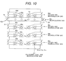
- FIG. 10 is a partial structural view of a pulverized coal boiler, viewed from the furnace front wall 2, after the pulverized coal boiler having two-stage after-air ports in the air combustion boiler system before retrofit shown in FIG. 9 has been retrofitted into a pulverized coal boiler having two-stage after-air ports in the oxyfuel combustion boiler system according to the present embodiment.
- the middle burners 7b are stopped from being used among the upper stage burners 7c, the middle stage burners 7b, and the lower stage burners 7a disposed on the furnace front wall 2 and the furnace back wall 3 before retrofit.
- the new burners 7d are installed to retrofit to the openings formed for installing main after-air ports 9a, without creating a new opening on the furnace wall downstream of the upper burners 7c, to extend the burner distance along the vertical direction between each burner of the lower stage burners 7a, the upper stage burners 7c, and the new burners 7d installed along the vertical direction on the furnace wall, thereby reducing the heat load in the furnace.
- windbox 8 is removed to install a windbox 8b, which is for supplying gas to the sub-after-air ports 9d, to the openings for installing sub-after-air ports 9d, and recirculation gas 69c is supplied to the windbox 8b through an air line 42b for a windbox.
- burners 7 are installed per each burner stage of the lower stage burners 7a, the middle stage burners 7b, and the upper stage burners 7c installed in the lower portion of the furnace front wall 2, as well as the burners 7d installed to the openings for installing after-air ports on the furnace front wall 2.
- Windboxes 90a, 90c, and 90d are retrofitted to install separately to the lower stage burners 7a, the upper stage burners 7c, and the burners 7d for installing to the openings of the after-air ports 9a respectively, and in the same manner as the previous embodiment shown in FIG.
- the pulverized coal fuel-and-recirculation gas 67 is supplied to the windboxes 90a, 90c, and 90d through the coal supply pipes 41 a, 41 c, and 41 d from the orthogonal direction to the furnace front wall 2, and oxygen-and-recirculation gases 68a, 68c, and 68d are supplied to the windboxes 90a, 90c, and 90d through the secondary and tertiary air introducing lines 43a, 43c, and 43d, and supplied into the furnace from the lower stage burners 7a, the upper stage burners 7c, and the burners 7d to adjust the heat load in the furnace.
- the recirculation gas 67 is supplied to the furnace through the burners 7d installed to the openings for installing after-air ports 9a, thereby allowing the heat load in the lateral direction in the furnace downstream of the windbox 8b to be adjusted.
- windboxes 90b are separately installed to the stopped middle stage burners 7b to supply the recirculation gas 69b to the windboxes 90b, using them as inlets for the recirculation gas 69b supplied from the middle stage burners 7b to the furnace 1.
- the pulverized coal boiler in the air combustion boiler system is retrofitted into the two-stage combustion pulverized coal boiler having burners and after-air ports in the oxyfuel combustion boiler system, not only the heat load on a furnace wall of the pulverized coal boiler can be reduced and retrofit into the pulverized coal boiler in the oxyfuel combustion boiler system which maintains structural reliability can be achieved at low cost in a short period of time, but also the heat load in the lateral direction in the furnace downstream of the windbox 8b can be adjusted.
- FIGS. 11 and 12 a method for retrofitting a pulverized coal boiler in which a pulverized coal boiler in the air combustion boiler system is retrofitted into a pulverized coal boiler in the oxyfuel combustion boiler system according to yet another embodiment of the present invention will be described using FIGS. 11 and 12 .
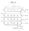
- FIG. 11 is a partial structural view of a pulverized coal boiler before retrofit, viewed from the furnace front wall 2, in which pulverized coal boiler in the air combustion boiler system has common-structure windboxes for burners.
- burners 7a, 7b, and 7c are installed per each burner stage of the upper stage burners 7c, the middle stage burners 7b, and the lower stage burners 7a in the lower portion of the furnace front wall 2.
- the pulverized coal fuel-and-air 65 is supplied through the coal supply pipes 41 a, 41 b, and 41 c from the orthogonal direction to the furnace front wall 2, and the air 62a, 62b, and 62c is supplied as secondary and tertiary air for burners to the burners 7a, 7b, and 7c through the secondary and tertiary air introducing lines 40a, 40b, and 40c and through common windboxes 80a, 80b, and 80c for burners.
- the windbox 8 for after-air ports is installed to the upper stage further above the upper stage burners 7c on the furnace wall and the air 62d is supplied from the secondary and tertiary air supply line 45 for burners through the air line 42 for a windbox.
- the air 62d introduced into the windbox 8 is supplied into the furnace 1 through the after-air ports 9.
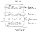
- FIG. 12 is a partial structural view of a pulverized coal boiler, viewed from the furnace front wall 2, after the pulverized coal boiler in the air combustion boiler system before retrofit shown in FIG. 11 has been retrofitted into a pulverized coal boiler in the oxyfuel combustion boiler system according to the present embodiment.
- the middle stage burners 7b are stopped from being used among the upper stage burners 7c, the middle stage burners 7b, and the lower stage burners 7a disposed on the furnace front wall 2 and the furnace back wall 3 before retrofit.
- the windbox 80b for the middle stage burners 7b is left untouched, the recirculation gas 69b is introduced into the windbox 80b through secondary and tertiary air introducing line 43b, and the recirculation gas 69b is supplied into the furnace 1 from the middle stage burners 7b to adjust the heat load in the furnace.
- the windbox 8 is removed and burners 7e are installed to retrofit to the openings for installing after-air ports 9, without creating a new opening, to extend the burner distance along the vertical direction between each burner of the lower stage burners 7a, the upper stage burners 7c, and the new burners 7e installed along the vertical direction on the furnace wall, thereby reducing the heat load in the furnace.
- the lower stage burners 7a and the upper stage burners 7c installed to the lower portion of the furnace front wall 2 and the furnace back wall 3 are retrofitted into separate structures by connecting each burner in the lower stage burners 7a and the upper stage burners 7c to each of the secondary and tertiary gas lines 68a and 68c for burners respectively.
- burners 7 are installed per each burner installation stage of the lower stage burners 7a and the upper stage burners 7c installed in the lower portion of the furnace front wall 2 and the furnace back wall 3 and the new burners 7e installed to the openings for installing after-air ports 9.
- windboxes 90a, 90c, and 90d are separately retrofitted to provide to the lower stage burners 7a, the upper stage burners 7c, and the burners 7e installed to the openings for installing after-air ports 9 respectively, and in the same manner as in the previous embodiment shown in FIG.
- the pulverized coal fuel-and-recirculation gas 67 is supplied to the windboxes 90a, 90c, and 90d through the coal supply pipes 41 a, 41 c, and 41 d from the orthogonal direction to the furnace front wall 2, the oxygen-and-recirculation gases 68a, 68c, and 68d are supplied to the windboxes 90a, 90c, and 90d through the secondary and tertiary air introducing lines 43a, 43c, and 43d, and supplied into the furnace from the lower stage burners 7a, the upper stage burners 7c and the burners 7e to adjust the heat load in the furnace.
- the windbox 80b is retrofitted to be supplied with the recirculation gas 69b through the secondary and tertiary air introducing line 43b, and the recirculation gas 69b introduced through the secondary and tertiary air introducing line 43b is supplied from the middle stage burners 7b into the furnace 1 to adjust the heat load in the furnace.
- the pulverized coal boiler in the air combustion boiler system is retrofitted into the two-stage combustion pulverized coal boiler having burners and after-air ports in the oxyfuel combustion boiler system, not only the heat load on a furnace wall of the pulverized coal boiler can be reduced and retrofit into the pulverized coal boiler in the oxyfuel combustion boiler system which maintains structural reliability can be achieved at low cost in a short period of time, but also the heat load in the lateral direction in the furnace can be adjusted over the entire region of the furnace where the burners are installed.
- the present invention is applicable to a method for retrofitting a pulverized coal boiler in the air combustion boiler system into a pulverized coal boiler in the oxyfuel combustion boiler system.
Landscapes
- Engineering & Computer Science (AREA)
- Chemical & Material Sciences (AREA)
- Combustion & Propulsion (AREA)
- Mechanical Engineering (AREA)
- General Engineering & Computer Science (AREA)
- Combustion Of Fluid Fuel (AREA)
- Air Supply (AREA)
Abstract
Description
- The present invention relates to a method for retrofitting a pulverized coal boiler in which a pulverized coal boiler in an air combustion boiler system is retrofitted into a pulverized coal boiler in an oxyfuel combustion boiler system.
- As part of measures against global warming, a method of burning a mixture gas of highly-pure oxygen and combustion exhaust gas instead of using conventional air has been proposed for burning fuel in a boiler. Hereinafter, this method is referred to as oxyfuel combustion, and a combustion method using air is referred to as air combustion.
- Since the majority of exhaust gas will be CO2 in oxyfuel combustion, the exhaust gas does not require condensation for recovering CO2. The exhaust gas can be directly compressed and cooled to separate CO2 for liquefaction. This is one of the effective ways to reduce CO2 emissions.
- As a conventional oxyfuel combustion boiler system, as stated in Japanese Patent application Laid-open No.
Hei 5(1993)-26409 - In addition, Japanese Patent application Laid-open No.
2001-201406 - Patent Document 1: Japanese Patent Application Laid-open No.
Hei 5(1993)-26409 - Patent Document 2: Japanese Patent Application Laid-open No.
2001-201406 - In the method for retrofitting a pulverized coal boiler in the air combustion system disclosed in Japanese Patent Application Laid-open No.
2001-201406 - In the oxyfuel combustion boiler system stated in Japanese Patent Application Laid-open No.
Hei 5(1993)-26409 - In this oxyfuel combustion boiler system, a reduction in the recirculation amount of the exhaust gas helps to avoid a loss in exhaust heat recovery and to reduce the power of a blower for blowing the recirculation gas; thus, it is advantageous in improving net thermal efficiency.
- On the other hand, the reduction in the recirculation amount of exhaust gas causes the oxygen concentration in combustion-enhancing gas to increase, raising the theoretical combustion temperature of fuel. As a result, the heat load on the furnace is drastically increased, which may damage the furnace due to temperatures exceeding the allowable temperature of metallic material making up the furnace. This will be a problem.
- It is an object of the present invention to provide a method for retrofitting a pulverized coal boiler in which, when a pulverized coal boiler in the air combustion system is retrofitted into a two-stage combustion pulverized coal boiler having a burner and an after-air port in the oxyfuel combustion boiler system, the heat load on a furnace wall of the pulverized coal boiler is reduced so that retrofit into a pulverized coal boiler in the oxyfuel combustion boiler system which maintains structural reliability can be achieved at low cost in a short period of time. This object is achieved by a method according to
claim 1. - One aspect of the invention relates to a method for retrofitting a pulverized coal boiler in an air combustion boiler system having a plurality of burners over a plurality of stages along the vertical direction on a wall surface of a furnace of the pulverized coal boiler and an after-air port for introducing air for two-stage combustion located above the burners to retrofit into a two-stage combustion pulverized coal boiler in an oxyfuel combustion boiler system, wherein an air separation unit for separating oxygen from air and a CO2 recovery device for absorbing and separating CO2 gas from combustion exhaust gas generated in the boiler furnace is installed, wherein the method for retrofitting the combustion pulverized coal boiler is comprising the steps of: stopping to supply fuel into the furnace from a burner located in a middle stage among the plurality of stages of burners installed on the wall surface of the furnace of the pulverized coal boiler; installing a new burner to an opening of the after-air port provided on the wall surface of the furnace of the pulverized coal boiler; and installing a supply line to introduce the oxygen manufactured by the air separation unit and part of the recirculation gas, which is part of the exhaust gas exhausted from the pulverized coal boiler, circulated into the pulverized coal boiler, to the plurality of stages of burners except for the stopped burner and to the new burner installed to the opening of the after-air port through the supply line, and supplying the oxygen and the recirculation gas from the plurality of stages of burners and the new burner into the furnace.
- A further aspect of the invention relates to a method for retrofitting a pulverized coal boiler in an air combustion boiler system having a plurality of burners over a plurality of stages along the vertical direction on a wall surface of a furnace of the pulverized coal boiler, a main after-air port and a sub-after-air port located in the lower stage of the main after-air port for introducing air for two-stage combustion located above the burners to retrofit into a two-stage combustion pulverized coal boiler in an oxyfuel combustion boiler system, wherein an air separation unit for separating oxygen from air and a CO2 recovery device for absorbing and separating CO2 gas from combustion exhaust gas generated in the boiler furnace is installed, wherein the method for retrofitting the combustion pulverized coal boiler is comprising the steps of: stopping to supply fuel into the furnace from a burner located in a middle stage among the plurality of stages of burners installed on the wall surface of the furnace of the pulverized coal boiler; installing another burner to an opening of the main after-air port provided on the wall surface of the furnace of the pulverized coal boiler; and installing a supply line to introduce the oxygen manufactured by the air separation unit and part of the recirculation gas, which is part of the exhaust gas exhausted from the pulverized coal boiler, circulated into the pulverized coal boiler, to the plurality of stages of burners except for the stopped burner and to the another burner installed to the opening of the main after-air port through the supply line, and supplying the oxygen and the recirculation gas from the plurality of stages of burners and the another burner into the furnace.
- A further aspect of the invention relates to a method for retrofitting a pulverized coal boiler in an air combustion boiler system having a plurality of burners over a plurality of stages along the vertical direction on a wall surface of a furnace of the pulverized coal boiler and an after-air port for introducing air for two-stage combustion located above the burners to retrofit into a two-stage combustion pulverized coal boiler in an oxyfuel combustion boiler system of the present invention, wherein an air separation unit for separating oxygen from air and a CO2 recovery device for absorbing and separating CO2 gas from combustion exhaust gas generated in the boiler furnace is installed, wherein the method for retrofitting the combustion pulverized coal boiler is comprising the steps of: stopping to supply fuel into the furnace from a burner located in a middle stage among the plurality of stages of burners installed on the wall surface of the furnace of the pulverized coal boiler; installing a new burner to an opening of the after-air port provided on the wall surface of the furnace of the pulverized coal boiler; installing a new windbox to the plurality of stages of burners except for the stopped burner and to the new burner installed to the opening of the after-air port; and installing a supply line to introduce the oxygen manufactured by the air separation unit and part of the recirculation gas, which is part of the exhaust gas exhausted from the pulverized coal boiler, circulated into the pulverized coal boiler, to the plurality of stages of burners and to the new windbox installed to the opening of the after-air port through the supply line, and supplying the oxygen and the recirculation gas from the plurality of stages of burners and the new burner into the furnace.
- According to the present invention, when retrofits a pulverized coal boiler in the air combustion boiler system into a two-stage combustion pulverized coal boiler having a burner and an after-air port in the oxyfuel combustion boiler system, the heat load on a furnace wall of the pulverized coal boiler can be reduced so that retrofit into the pulverized coal boiler in the oxyfuel combustion boiler system which maintains structural reliability can be achieved at low cost in a short period of time.
-
-
FIG. 1 is a structural view showing a furnace of a pulverized coal boiler for the present invention and the location of burners and openings for installing after-air ports. -
FIG. 2 is an overall structural view showing an air combustion boiler system including the pulverized coal boiler for the present invention before retrofit. -
FIG. 3 is a partial structural view of the pulverized coal boiler in the air combustion boiler system before retrofit, viewed from the furnace front wall. -
FIG. 4 is a structural view showing an oxyfuel combustion boiler system after retrofit of the pulverized coal boiler to have been retrofitted into a pulverized coal boiler in an oxyfuel combustion boiler system according to an embodiment of the present invention. -
FIG. 5 is a schematic structural view showing a furnace of the pulverized coal boiler and burners installed to the furnace after retrofit in the embodiment of the present invention shown inFIG. 4 . -
FIG. 6 is a partial structural view of the pulverized coal boiler after retrofit to have been retrofitted into the pulverized coal boiler in the oxyfuel combustion boiler system according to an embodiment of the present invention, viewed from the furnace front wall. -
FIG. 7 is a pattern diagram showing the heat load distribution in the furnaces in air combustion and in oxyfuel combustion having an oxygen concentration that makes the heat absorbing condition of the oxyfuel combustion the same as that of the air combustion. -
FIG. 8 is a pattern diagram showing the heat load distribution in the furnace of the pulverized coal boilers before retrofit and after retrofit to have been retrofitted into the oxyfuel combustion boiler system according to an embodiment of the present invention. -
FIG. 9 is a partial structural view showing a furnace having two-stage after-air ports of a pulverized coal boiler in an air combustion boiler system before retrofit. -
FIG. 10 is a partial structural view showing the furnace having two-stage after-air ports of the pulverized coal boiler after retrofit to have been retrofitted into a pulverized coal boiler in an oxyfuel combustion boiler system according to another embodiment of the present invention. -
FIG. 11 is a partial structural view showing a furnace having a common-style windbox for a burner of a pulverized coal boiler in an air combustion boiler system before retrofit. -
FIG. 12 is a partial structural view showing the furnace having a common-style windbox for a burner of the pulverized coal boiler after retrofit to have been retrofitted into a pulverized coal boiler in an oxyfuel combustion boiler system according to yet another embodiment of the present invention. - A method for retrofitting a pulverized coal boiler according to an embodiment of the present invention is described below with reference to the figures.
- The method for retrofitting a pulverized coal boiler in an air combustion boiler system into a pulverized coal boiler in an oxyfuel combustion boiler system according to an embodiment of the present invention will be described.
- At first, the structure of a furnace of a pulverized coal boiler for the present invention will be described using
FIG. 1 . - In the pulverized coal boiler shown in
FIG. 1 , furnace walls making up afurnace 1 include a furnacefront wall 2, afurnace back wall 3 opposing thefurnace front wall 2, andfurnace side walls 4 which are the both side walls between thefurnace front wall 2 and thefurnace back wall 3; and these furnace walls surround thefurnace 1 to form a furnace combustion space for burning pulverized coal fuel in thefurnace 1. - Three stages of openings (
upper stage openings 5a,middle stage openings 5b, andlower stage openings 5c) for installing burners are provided in the lower portions of the furnacefront wall 2 and thefurnace back wall 3. Fouropenings - On the furnace wall in the upper stage further above the location of the
upper stage openings 5a for installingupper burners 7c, fouropenings 6a for installing after-air ports, which supply after-air into the furnace, are provided per stage, and the after-air port is set up in each opening 6a. - When the furnace is a two-stage after-air port type furnace,
openings 6b for setting up sub-after-air ports are provided below theopenings 6a for setting up the main after-air ports. - Although the present embodiment shows the four
openings openings 6a for setting up after-air ports, the present invention has no limit to the number of openings on the pulverized coal boiler for retrofit. - In addition, the present invention is not limited to the pulverized coal boiler for retrofitting to a two-stage after-air style boiler having a main after-air port and a sub-after-air port.
- Next, using
FIG. 2 , an overall structure of the air combustion boiler system for the present invention including, as a component, the above-described furnace of the pulverized coal boiler before retrofit will be described. - In
FIG. 2 , the air combustion boiler system having the pulverized coal boiler before retrofit includes thefurnace 1, and in the lower portions of thefurnace front wall 2 of thefurnace 1 and the furnace backwall 3 opposing thefurnace front wall 2, a plurality of stages of burners are provided facing each other along the vertical direction over three stages oflower stage burners 7a,middle stage burners 7b, and theupper stage burners 7c. - Two
coal pulverizers 10 for pulverizing coal fuel into pulverized coal are each provided to the burner stages separately set up as the upper, middle, and lower stages on thefurnace front wall 2 and the furnace backwall 3 of the furnace 1 (a total of six coal pulverizers in the upper, middle, and lower stages). -
Coal 12 is a fuel stored in ahopper 11, and after being pulverized in thecoal pulverizer 10, the pulverized coal is transported byair 61 supplied from ablower 31 to thecoal pulverizer 10 through a pulverized coal transportingair supply line 46. - The pulverized coal is then supplied with the
air 61 to each of thelower stage burners 7a, themiddle stage burners 7b, and theupper stage burners 7c throughcoal supply pipes furnace 1 for burning. At the same time,air 62 supplied from ablower 32 as secondary and tertiary air for burners is supplied from a secondary and tertiaryair supply line 45 for burners to thelower stage burners 7a, themiddle stage burners 7b, and theupper stage burners 7c through secondary and tertiaryair supply lines - In the downstream side of the furnace walls on which the
lower stage burners 7a, themiddle stage burners 7b, and theupper stage burners 7c are installed, and in the upper stages further above the installation of theupper stage burners 7c on thefurnace front wall 2 and the furnace backwall 3, a plurality of after-air ports 9a are set up facing each other. These after-air ports 9a supply additional air for two-stage combustion into thefurnace 1. - The
air 62 supplied from theblower 32 is supplied to each burner 7, as well as to each after-air port 9a through awindbox 8, after being preheated by anair preheater 19 which exchanges heat withexhaust gas 63 exhausted from thefurnace 1 through anexhaust gas line 47. - Additionally, with regard to the
furnace 1 of the pulverized coal boiler in the embodiment of the present invention, a partial structure of the furnace front wall of the pulverized coal boiler in the air combustion boiler system before retrofit, viewed from the furnace front wall, will be explained usingFIG. 3 . -
FIG. 3 is a partial structural view of the pulverized coal boiler in the air combustion boiler system before retrofit, viewed from thefurnace front wall 2. Four burners are installed for each stage of theupper stage burners 7c, themiddle stage burners 7b, and thelower stage burners 7a in the lower portion of thefurnace front wall 2. - Pulverized coal fuel-and-
air 65 is supplied through thecoal supply pipes furnace front wall 2, andair air introducing lines - The
windbox 8 is installed on the furnace wall in the upper stage further above the installation of theupper stage burners 7c, andair 62d is supplied from the secondary and tertiaryair supply line 45 for burners through anair line 42a for a windbox. Theair 62d introduced into thewindbox 8 is supplied into thefurnace 1 through the after-air ports 9a. - Next, a method for retrofitting the above-mentioned air combustion boiler system into an oxyfuel combustion boiler system will be explained below.
-
FIG. 4 is an overall structural view in which the pulverized coal boiler in the air combustion boiler system is retrofitted into a pulverized coal boiler in the oxyfuel combustion boiler system according to the embodiment of the present invention. - In the pulverized coal boiler retrofitted into the oxyfuel combustion boiler system according to the present embodiment, shown in
FIG. 4 , themiddle stage burners 7b are stopped from supplying fuel into the furnace, in which casemiddle stage burners 7b are burners located in the middle stage among theupper stage burners 7c, themiddle stage burners 7b, and thelower stage burners 7a disposed on thefurnace front wall 2 and the furnace backwall 3 before retrofit. - Since the pulverized coal boiler in the present embodiment is provided with three-stage burners having the
upper stage burners 7c, themiddle stage burners 7b, and thelower stage burners 7a disposed on thefurnace front wall 2 and the furnace backwall 3 of thefurnace 1, the burners located in the middle stage will be themiddle stage burners 7b; however, when, for example, four stages of burners are disposed on thefurnace front wall 2 and the furnace backwall 3, the burners located in the middle stage will be either the burners in the second stage from the bottom or those in the second stage from the top. -
New burners 7d are, then, installed to theopenings 6a for installing after-air ports without creating a new opening on a wall surface of thefurnace 1, extending each burner distance between the plurality of burners disposed along the vertical direction. - In the oxyfuel combustion boiler system retrofitted into in the present embodiment, an
oxygen separator 17 and agas mixer 18 are installed. Pure oxygen is made by theoxygen separator 17 having a cryogenic separation device and the like, which separates oxygen fromair 65 supplied by ablower 33. - In the oxyfuel combustion boiler system, the
exhaust gas line 47 for passing down exhaust gas, which is mainly CO2, exhausted from thefurnace 1 after pulverized coal has been burnt in thefurnace 1 of the pulverized coal boiler is provided with agas refiner 13 for refining the exhaust gas; agas preheater 14 for exchanging heat using, as a heat source, the exhaust gas which has passed through thegas refiner 13; acryogenic dehumidifier 15 for dehumidifying the exhaust gas which has passed through thegas preheater 14; and a CO2 recovery device 16 for recovering CO2 from the exhaust gas which has passed through thecryogenic dehumidifier 15 by cooling the gas. CO2 in the exhaust gas is recovered as liquefied CO2 (66) by the CO2 recovery device 16. - In addition, part of the exhaust gas which has passed through the
cryogenic dehumidifier 15 flows through aline 48 to thegas preheater 14, and after being preheated by thegas preheater 14, it is supplied as recirculation gas to thegas mixer 18 throughrecirculation lines blower 34. - The oxygen made by the
oxygen separator 17, supplied through anoxygen supply line 56 into thegas mixer 18, is mixed with the recirculation gas supplied through therecirculation line 53, and the mixed gas (the oxygen and the recirculation gas) is supplied through asupply line 55 for the mixed gas of oxygen and recirculation gas and through secondary and tertiary air introduction lines 43, which are supply lines for the oxygen and recirculation gas, to each of thelower stage burners 7a, theupper stage burners 7c, and theburners 7d installed to the openings 6 for installing after-air ports. - Each burner stage of the
upper stage burners 7c, thelower stage burners 7a, and theburners 7d separately installed to the openings 6 for installing after-air ports on thefurnace front wall 2 and the furnace backwall 3 of thefurnace 1 is provided with twocoal pulverizers 10 for supplying a pulverized coal fuel. - As a fuel, the
coal 12 is pulverized in thecoal pulverizer 10, and after turning into pulverized coal, it is transported by the recirculation gas flowing through arecirculation gas line 50. Then, the pulverized coal transported by the recirculation gas is supplied along with the recirculation gas to each of thelower stage burners 7a, theupper stage burners 7c, and theburners 7d through thecoal supply pipes furnace 1 for burning. - The pulverized coal ejected into the
furnace 1 from each burner may be difficult to ignite due to low oxygen concentration in the recirculation gas; however, the amount of oxygen supplied to thecoal pulverizer 10 can be adjusted by operating aflow rate adjuster 25 for adding oxygen to the recirculation gas, provided to anoxygen supply line 54 for supplying oxygen to the recirculation gas for transporting pulverized coal, to improve ignition performance of the pulverized coal by increasing the oxygen concentration as necessary. - The stopped
middle stage burners 7b are used as inlets for recirculation gas 69. The recirculation gas passed through asupply line 51 for supplying the recirculation gas to the stopped burner is supplied from theburners 7b into thefurnace 1, and the supply amount of the recirculation gas 69 is adjusted by aflow rate adjuster 28 installed to the recirculationgas supply line 51 to adjust the heat load in the furnace. - The exhaust gas, which is mainly CO2, exhausted from the
furnace 1 after burning the pulverized coal through theexhaust gas line 47 is refined in thegas refiner 13 installed to theexhaust gas line 47, then in sequence, goes through heat exchange in thegas preheater 14 downstream, and after being dehumidified in thecryogenic dehumidifier 15 further downstream, it is cooled in the CO2 recovery device to be recovered as the liquefied CO2 (66). - On the other hand, part of the exhaust gas exhausted from the
furnace 1 through theexhaust gas line 47 passes through therecirculation line 48 for refined exhaust gas, and after being preheated by thegas preheater 14, it is supplied by theblower 34 to therecirculation gas line 49 as the recirculation gas 69. - This recirculation gas 69 supplied to the
recirculation gas line 49 flows down separately into each of the three lines of the recirculationgas supply line 51 to the stopped burners, the circulationgas supply line 52 from a hopper, and therecirculation line 53, from therecirculation gas line 49. - The recirculation gas 69 that separately flows down to the recirculation
gas supply line 51 is sent to the stoppedburners 7b to adjust the heat load in thefurnace 1, and the recirculation gas 69 that separately flows down to the recirculationgas supply line 52 is recirculated from the lower portion of thefurnace 1. - The recirculation gas that separately flows down to the
recirculation line 53 is supplied to thegas mixer 18, mixed in thegas mixer 18 with oxygen made in theair separation unit 17, and supplied as combustion-enhancing gas for burning pulverized coal from each of secondary and tertiaryair introducing lines lower stage burners 7a, theupper stage burners 7c, and theburners 7d, for recirculation. -
FIG. 5 is a schematic diagram showing the furnace of the pulverized coal boiler and the burners installed to the furnace after the pulverized coal boiler in the air combustion boiler system is retrofitted into the oxyfuel combustion boiler system according to the present embodiment. In thefurnace 1, as shown inFIG. 5 , theburners 7d are installed to theopenings 6a for installing after-air ports. In the figure, the coal supply pipes 41 and the secondary and tertiary gas supply lines 43 for burners are not shown. -
FIG. 6 is a partial structural view of the pulverized coal boiler after the pulverized coal boiler in the air combustion boiler system is retrofitted into the oxyfuel combustion boiler system according to the present embodiment, viewed from thefurnace front wall 2. Four burners are installed per each burner installation stage of thelower stage burners 7a, theupper stage burner 7c, and the stoppedmiddle stage burners 7b installed in the lower portion of thefurnace front wall 2, as well as theburners 7d installed to the openings 6 for installing after-air ports on thefurnace front wall 2. - Then, the
lower stage burners 7a, theupper stage burners 7c, and theburners 7d installed to the openings 6 for installing after-air ports are supplied with pulverized coal-and-recirculation gas 67 through thecoal supply pipes furnace front wall 2, and with oxygen-and-recirculation gases air introducing lines - In addition,
recirculation gas 69b supplied to the stoppedmiddle stage burners 7b through secondary and tertiaryair introducing line 43b is supplied from themiddle stage burners 7b into thefurnace 1 to adjust the heat load in thefurnace 1. - An example of the embodiment of the present invention in which a pulverized coal boiler in the air combustion boiler system is retrofitted into a pulverized coal boiler in the oxyfuel combustion boiler system has been explained above. Next, with regard to a change in the composition of combustion-enhancing gas supplied to the pulverized coal boiler as a combustion-enhancing gas mixed from oxygen and recirculation gas, a problem arising from it and a solution to the problem will be discussed.
- When a pulverized coal boiler in the air combustion boiler system is retrofitted into a pulverized coal boiler in the oxyfuel combustion boiler system, it is preferable from the standpoint of retrofit cost that the balance of the heat absorption amount of each heat exchanger in the air combustion also be kept in the oxyfuel combustion.
- This is because, in the design stage of the boiler, material for the heat exchangers is selected based on the balance of the heat absorption amount (steam temperature and pressure in a water tube and gas temperature outside the water tube) of each heat exchanger installed to the
furnace 1. In the heat exchanger, a high price material with superior heat resistance is used in a high temperature region, and a low price material with lesser heat resistance is used in a relatively low temperature region. - When the boiler system is changed from air combustion to oxyfuel combustion, greatly changing the balance of the heat absorption in the oxyfuel combustion from the balance of the heat absorption in the air combustion, the conditions such as temperature based on which material was selected in the design stage will be changed. This brings anticipation that if the system is left as-is, its operation may not be continued due to the heat resistance of the material.
- In such case, retrofit becomes necessary to change the heat transmission area in each heat exchanger so that temperatures do not exceed the service temperature limit of the material (addition or deletion of a water tube). From the above requirement, if the balance of the heat absorption amount in the air combustion can be re-created in the oxyfuel combustion, then the retrofit for changing the heat transmission areas will be unnecessary, thus reducing the retrofit cost.
- In order to achieve the same heat absorption condition as the air combustion by using the existing group of heat exchangers, the oxygen concentration of combustion-enhancing gas is required to be increased to at least the oxygen concentration in air (21 %) or more. When the oxygen concentration is increased to 21 % or more, however, the burning temperature of pulverized coal will go up, causing the heat load in the furnace to increase. This is a problem.
-
FIG. 7 is a pattern diagram showing the effect of oxyfuel combustion on the heat load distribution in the furnace. InFIG. 7 , an alternate long and short dash line (b) shows the heat load distribution in the furnace in the air combustion, and a solid line (a) shows the head load distribution in thefurnace 1 when the oxygen concentration is increased to match the heat absorption condition in the air combustion. As shown by the solid line (a) inFIG. 7 , when the oxygen concentration is increased in the oxyfuel combustion, the heat load in the furnace is increased. - In the oxyfuel combustion boiler system, the oxygen concentration in combustion-enhancing gas can be varied by adjusting the amount of recirculation gas. In order to reduce the heat load in the
furnace 1, the amount of recirculation gas can be increased to reduce the oxygen concentration. When the amount of recirculation gas is increased, however, the blower power for blowing the recirculation gas will be increased. This is disadvantageous in the view of net thermal efficiency. - Thus, in the method for retrofitting into the pulverized coal boiler in the oxyfuel combustion boiler system according to the present embodiment, the
middle stage burners 7b are stopped from being used and at the same time, thenew burners 7d are installed to retrofit to the openings for installing after-air ports, to extend the burner distance along the vertical direction between each burner of thelower stage burners 7a, theupper stage burners 7c, and thenew burners 7d installed on the furnace walls, thereby reducing the heat load in the furnace. -
FIG. 8 is a pattern diagram showing a reduction in heat load when the pulverized coal boiler in the air combustion system is retrofitted into the pulverized coal boiler in the oxyfuel combustion boiler system according to the embodiment of the present invention. - In
FIG. 8 , a solid line (a) shows the heat load distribution in thefurnace 1 when the oxygen concentration is increased to match the heat absorption condition of the air combustion, and an alternate long and short dash line (b) shows the heat load distribution in thefurnace 1 when the oxygen concentration is increased by increasing the amount of recirculation gas. - A broken line (c) in
FIG. 8 shows the heat load distribution in thefurnace 1, which is reduced by retrofit into the pulverized coal boiler in the oxyfuel combustion boiler system according to the present embodiment. - As can be understood by comparing each heat load distribution in the
furnace 1 shown inFIG. 8 , the retrofit into the pulverized coal boiler in the oxyfuel combustion boiler system according to the present embodiment can reduce the heat load in thefurnace 1 without increasing house power. - In addition to the method for retrofitting into the pulverized coal boiler in the oxyfuel combustion boiler system according to the present embodiment, the supply amount of recirculation gas by the
blower 34 for supplying the recirculation gas to the pulverized coal boiler can be reduced to increase the oxygen concentration in combustion-enhancing gas, which is mixed from oxygen and recirculation gas to be supplied to the pulverized coal boiler. This not only reduces the heat load in thefurnace 1 to a desired state, but also reduces the heat recovery loss and the blower power for blowing the recirculation gas, thereby improving the net thermal efficiency of the oxyfuel combustion boiler system. - Furthermore, in the method for retrofitting into the pulverized coal boiler in the oxyfuel combustion boiler system according to the present embodiment, the burners can be installed without making a new opening in the wall surface of the
furnace 1 so that a pulverized coal boiler which maintains its structural reliability can be achieved at low cost in a short period of time. - According to the present embodiment, when a pulverized coal boiler in the air combustion boiler system is retrofitted into a two-stage combustion pulverized coal boiler having a burner and an after-air port in the oxyfuel combustion boiler system, the heat load on a furnace wall of the pulverized coal boiler can be reduced so that retrofit into the pulverized coal boiler in the oxyfuel combustion boiler system which can maintain structural reliability can be achieved at low cost in a short period of time.
- Next, a method for retrofitting a pulverized coal boiler in the air combustion boiler system into a pulverized coal boiler in the oxyfuel combustion boiler system according to another embodiment of the present invention will be described using
FIGS. 9 and10 . - For the method for retrofitting a pulverized coal boiler in the air combustion boiler system before retrofit shown in
FIG. 9 is retrofitted into the pulverized coal boiler in the oxyfuel combustion boiler system shown inFIG. 10 according to the present embodiment, since the overall structure of the pulverized coal boiler according to the present embodiment shown inFIG. 10 has some common components with the method for retrofitting the pulverized coal boiler into the oxyfuel combustion boiler system in the previous embodiment shown inFIG. 4 , the common components between them are not described and only different components in the present embodiment are explained below. - A method for retrofitting a pulverized coal boiler having two-stage after-air ports in a furnace will be described as the method for retrofitting the pulverized coal boiler in the air combustion boiler system shown in
FIG. 9 into the pulverized coal boiler in the oxyfuel combustion boiler system according to the present embodiment. - Two-stage after-air ports installed on a furnace wall of the pulverized coal boiler in the air combustion boiler system before retrofit shown in
FIG. 9 include main after-air ports 9a and sub-after-air ports 9b in the lower stage of the main after-air ports 9a. -
FIG. 9 is a partial structural view of the pulverized coal boiler having two-stage after-air ports in the air combustion boiler system before retrofit, viewed from thefurnace front wall 2 of thefurnace 1. Fourburners upper stage burners 7c, themiddle stage burners 7b, and thelower stage burners 7a in the lower portion of thefurnace front wall 2. - The pulverized coal fuel-and-
air 65 is supplied through each of thecoal supply pipes furnace front wall 2, and theair burners air introducing lines - In the upper stage on the furnace wall further above the installation of the
upper stage burners 7c, thewindbox 8 is installed, and theair 62d is supplied to thewindbox 8 from the secondary and tertiaryair supply line 45 for burners through theair line 42a for a windbox. - The
air 62d introduced into thewindbox 8 is supplied into thefurnace 1 through the main after-air ports 9a and the sub-after-air ports 9b, which are openings formed on the furnace wall. Thewindbox 8 for two-stage after-air ports can supply air to both the main after-air ports 9a and the sub-after-air ports 9b. -
FIG. 10 is a partial structural view of a pulverized coal boiler, viewed from thefurnace front wall 2, after the pulverized coal boiler having two-stage after-air ports in the air combustion boiler system before retrofit shown inFIG. 9 has been retrofitted into a pulverized coal boiler having two-stage after-air ports in the oxyfuel combustion boiler system according to the present embodiment. - In the pulverized coal boiler after retrofitted into the oxyfuel combustion boiler system according to the present embodiment shown in
FIG. 10 , themiddle burners 7b are stopped from being used among theupper stage burners 7c, themiddle stage burners 7b, and thelower stage burners 7a disposed on thefurnace front wall 2 and the furnace backwall 3 before retrofit. - Furthermore, the
new burners 7d are installed to retrofit to the openings formed for installing main after-air ports 9a, without creating a new opening on the furnace wall downstream of theupper burners 7c, to extend the burner distance along the vertical direction between each burner of thelower stage burners 7a, theupper stage burners 7c, and thenew burners 7d installed along the vertical direction on the furnace wall, thereby reducing the heat load in the furnace. - In addition, the
windbox 8 is removed to install awindbox 8b, which is for supplying gas to the sub-after-air ports 9d, to the openings for installing sub-after-air ports 9d, andrecirculation gas 69c is supplied to thewindbox 8b through anair line 42b for a windbox. - The
recirculation gas 69c introduced to thewindbox 8b through theair line 42b for a windbox, then, is supplied from the sub-after-air ports 9d into thefurnace 1 to adjust the heat load in thefurnace 1. - Four burners 7 are installed per each burner stage of the
lower stage burners 7a, themiddle stage burners 7b, and theupper stage burners 7c installed in the lower portion of thefurnace front wall 2, as well as theburners 7d installed to the openings for installing after-air ports on thefurnace front wall 2. -
Windboxes lower stage burners 7a, theupper stage burners 7c, and theburners 7d for installing to the openings of the after-air ports 9a respectively, and in the same manner as the previous embodiment shown inFIG. 4 , the pulverized coal fuel-and-recirculation gas 67 is supplied to thewindboxes coal supply pipes furnace front wall 2, and oxygen-and-recirculation gases windboxes air introducing lines lower stage burners 7a, theupper stage burners 7c, and theburners 7d to adjust the heat load in the furnace. - The
recirculation gas 67 is supplied to the furnace through theburners 7d installed to the openings for installing after-air ports 9a, thereby allowing the heat load in the lateral direction in the furnace downstream of thewindbox 8b to be adjusted. - In addition,
windboxes 90b are separately installed to the stoppedmiddle stage burners 7b to supply therecirculation gas 69b to the windboxes 90b, using them as inlets for therecirculation gas 69b supplied from themiddle stage burners 7b to thefurnace 1. - As shown in the above description, according to the present embodiment, when the pulverized coal boiler in the air combustion boiler system is retrofitted into the two-stage combustion pulverized coal boiler having burners and after-air ports in the oxyfuel combustion boiler system, not only the heat load on a furnace wall of the pulverized coal boiler can be reduced and retrofit into the pulverized coal boiler in the oxyfuel combustion boiler system which maintains structural reliability can be achieved at low cost in a short period of time, but also the heat load in the lateral direction in the furnace downstream of the
windbox 8b can be adjusted. - Next, a method for retrofitting a pulverized coal boiler in which a pulverized coal boiler in the air combustion boiler system is retrofitted into a pulverized coal boiler in the oxyfuel combustion boiler system according to yet another embodiment of the present invention will be described using
FIGS. 11 and12 . - For the method for retrofitting a pulverized coal boiler in which the pulverized coal boiler in the air combustion boiler system before retrofit shown in
FIG. 11 is retrofitted into the pulverized coal boiler in the oxyfuel combustion boiler system shown inFIG. 12 according to the present embodiment, since the overall structure of the pulverized coal boiler shown inFIG. 12 has some common components with the method for retrofitting pulverized coal boiler in the previous embodiment shown inFIG. 4 , the common components between them are not described and only different components in the present embodiment are explained below. -
FIG. 11 is a partial structural view of a pulverized coal boiler before retrofit, viewed from thefurnace front wall 2, in which pulverized coal boiler in the air combustion boiler system has common-structure windboxes for burners. - In the pulverized coal boiler in the air combustion boiler system before retrofit shown in
FIG. 11 , fourburners upper stage burners 7c, themiddle stage burners 7b, and thelower stage burners 7a in the lower portion of thefurnace front wall 2. - The pulverized coal fuel-and-
air 65 is supplied through thecoal supply pipes furnace front wall 2, and theair burners air introducing lines common windboxes - The
windbox 8 for after-air ports is installed to the upper stage further above theupper stage burners 7c on the furnace wall and theair 62d is supplied from the secondary and tertiaryair supply line 45 for burners through theair line 42 for a windbox. - The
air 62d introduced into thewindbox 8 is supplied into thefurnace 1 through the after-air ports 9. -
FIG. 12 is a partial structural view of a pulverized coal boiler, viewed from thefurnace front wall 2, after the pulverized coal boiler in the air combustion boiler system before retrofit shown inFIG. 11 has been retrofitted into a pulverized coal boiler in the oxyfuel combustion boiler system according to the present embodiment. - In the pulverized coal boiler after retrofit into the oxyfuel combustion boiler system according to the present embodiment shown in
FIG. 12 , themiddle stage burners 7b are stopped from being used among theupper stage burners 7c, themiddle stage burners 7b, and thelower stage burners 7a disposed on thefurnace front wall 2 and the furnace backwall 3 before retrofit. - The
windbox 80b for themiddle stage burners 7b is left untouched, therecirculation gas 69b is introduced into thewindbox 80b through secondary and tertiaryair introducing line 43b, and therecirculation gas 69b is supplied into thefurnace 1 from themiddle stage burners 7b to adjust the heat load in the furnace. - In addition, the
windbox 8 is removed andburners 7e are installed to retrofit to the openings for installing after-air ports 9, without creating a new opening, to extend the burner distance along the vertical direction between each burner of thelower stage burners 7a, theupper stage burners 7c, and thenew burners 7e installed along the vertical direction on the furnace wall, thereby reducing the heat load in the furnace. - On the other hand, in order to allow slight adjustments of the heat load in the furnace, the
lower stage burners 7a and theupper stage burners 7c installed to the lower portion of thefurnace front wall 2 and the furnace backwall 3 are retrofitted into separate structures by connecting each burner in thelower stage burners 7a and theupper stage burners 7c to each of the secondary andtertiary gas lines - In the pulverized coal boiler shown in
FIG. 12 , four burners 7 are installed per each burner installation stage of thelower stage burners 7a and theupper stage burners 7c installed in the lower portion of thefurnace front wall 2 and the furnace backwall 3 and thenew burners 7e installed to the openings for installing after-air ports 9. - The
windboxes lower stage burners 7a, theupper stage burners 7c, and theburners 7e installed to the openings for installing after-air ports 9 respectively, and in the same manner as in the previous embodiment shown inFIG. 4 , the pulverized coal fuel-and-recirculation gas 67 is supplied to thewindboxes coal supply pipes furnace front wall 2, the oxygen-and-recirculation gases windboxes air introducing lines lower stage burners 7a, theupper stage burners 7c and theburners 7e to adjust the heat load in the furnace. - To utilize the
windbox 80b installed to the stoppedburners 7b, thewindbox 80b is retrofitted to be supplied with therecirculation gas 69b through the secondary and tertiaryair introducing line 43b, and therecirculation gas 69b introduced through the secondary and tertiaryair introducing line 43b is supplied from themiddle stage burners 7b into thefurnace 1 to adjust the heat load in the furnace. - As shown in the above description, according to the present embodiment, when the pulverized coal boiler in the air combustion boiler system is retrofitted into the two-stage combustion pulverized coal boiler having burners and after-air ports in the oxyfuel combustion boiler system, not only the heat load on a furnace wall of the pulverized coal boiler can be reduced and retrofit into the pulverized coal boiler in the oxyfuel combustion boiler system which maintains structural reliability can be achieved at low cost in a short period of time, but also the heat load in the lateral direction in the furnace can be adjusted over the entire region of the furnace where the burners are installed.
- The present invention is applicable to a method for retrofitting a pulverized coal boiler in the air combustion boiler system into a pulverized coal boiler in the oxyfuel combustion boiler system.
- The above embodiments of the invention as well as the appended claims and figures show multiple characterizing features of the invention in specific combinations. The skilled person will easily be able to consider further combinations or subcombinations of these features in order to adapt the invention as defined in the in the claims to his specific needs.
Claims (6)
- A method for retrofitting a pulverized coal boiler in an air combustion boiler system having a plurality of burners (7a, 7b, 7c) over a plurality of stages along the vertical direction on a wall (2) surface of a furnace (1) of the pulverized coal boiler and an after-air port (9) for introducing air for two-stage combustion located above the burners (7a, 7b, 7c) to retrofit into a two-stage combustion pulverized coal boiler in an oxyfuel combustion boiler system, wherein an air separation unit (17) for separating oxygen from air and a CO2 recovery device (16) for absorbing and separating CO2 gas from combustion exhaust gas generated in the boiler furnace (1) is installed,
wherein the method for retrofitting the combustion pulverized coal boiler is comprising the steps of:stopping to supply fuel into the furnace (1) from a burner (7b) located in a middle stage among the plurality of stages of burners (7a, 7b, 7c) installed on the wall (2) surface of the furnace (1) of the pulverized coal boiler;installing a new burner (7d) to an opening (6a, 6b) of the after-air port (9) provided on the wall (2) surface of the furnace (1) of the pulverized coal boiler; andinstalling a supply line to introduce the oxygen manufactured by the air separation unit (17) and part of the recirculation gas, which is part of the exhaust gas exhausted from the pulverized coal boiler, circulated into the pulverized coal boiler, to at least the plurality of stages of burners (7a, 7b, 7c) except for the stopped burner (7b) and to the new burner (7d) installed to the opening of the after-air port (9) through the supply line (51), and supplying the oxygen and the recirculation gas from the plurality of stages of burners (7a, 7b, 7c) and the new burner (7d) into the furnace (1). - The method for retrofitting a pulverized coal boiler according to claim 1,
wherein the method for retrofitting the combustion pulverized coal boiler is further comprising the steps of:installing an another supply line (43b) to introduce part of the recirculation gas, which is part of the exhaust gas exhausted from the pulverized coal boiler, circulated into the pulverized coal boiler, to the stopped burner (7b) through the another supply line, and supplying the recirculation gas from the stopped burners (7b) into the furnace (1). - A method for retrofitting a pulverized coal boiler according to one of the preceding claims, wherein the combustion boiler system has, a main after-air port (9a) and a sub-after-air port (9b) located in the lower stage of the main after-air port (9a) for introducing air for two-stage combustion located above the burners (7a, 7b, 7c) and wherein said new burner is another burner (7d) installed to an opening (6a, 6b) of the main after-air port (9a); and wherein said supply line (55) is installed to introduce the oxygen manufactured by the air separation unit (17) and part of the recirculation gas, which is part of the exhaust gas exhausted from the pulverized coal boiler, circulated into the pulverized coal boiler, to the plurality of stages of burners (7a, 7b, 7c) except for the stopped burner (7b) and to the another burner (7d) installed to the opening of the main after-air port (9a) through the supply line (55), and supplying the oxygen and the recirculation gas from the plurality of stages of burners (7a, 7b, 7c) and the another burner (7d) into the furnace (1).
- The method for retrofitting a pulverized coal boiler according to claim 3,
wherein the method for retrofitting the combustion pulverized coal boiler is comprising the steps of:installing an another supply line to introduce part of the recirculation gas, which is part of the exhaust gas exhausted from the pulverized coal boiler, circulated into the pulverized coal boiler, to the stopped burner (7b) through the another supply line, and supplying the recirculation gas from the stopped burners into the furnace (1); andinstalling a other supply line to introduce part of the recirculation gas to a new windbox installed to an opening of the sub after-air port (9) provided on the wall (2) surface of the furnace (1) through the other supply line, and supplying the recirculation gas from the stopped burner and the opening of the sub after-air port (9) into the furnace (1). - A method for retrofitting a pulverized coal boiler according to claim 1,
wherein the method for retrofitting the combustion pulverized coal boiler is further comprising the step:installing a new windbox (8) to the plurality of stages of burners (7a, 7b, 7c) except for the stopped burner (7b) and to the new burner (7d) installed to the opening of the after-air port (9); wherein saidsupply line introduces the oxygen and part of the recirculation gas to the plurality of stages of burners (7a, 7b, 7c) and to the new windbox (8) installed to the opening of the after-air port (9) through the supply line. - The method for retrofitting a pulverized coal boiler according to claim 5,
wherein the method for retrofitting the combustion pulverized coal boiler is comprising the steps of:installing an another supply line to introduce part of the recirculation gas, which is part of the exhaust gas exhausted from the pulverized coal boiler, circulated into the pulverized coal boiler, to the stopped burner through the another supply line, and supplying the recirculation gas from the stopped burners into the furnace (1).
Applications Claiming Priority (1)
| Application Number | Priority Date | Filing Date | Title |
|---|---|---|---|
| JP2009243581A JP5331648B2 (en) | 2009-10-22 | 2009-10-22 | How to modify a pulverized coal boiler |
Publications (3)
| Publication Number | Publication Date |
|---|---|
| EP2314920A2 true EP2314920A2 (en) | 2011-04-27 |
| EP2314920A3 EP2314920A3 (en) | 2014-11-26 |
| EP2314920B1 EP2314920B1 (en) | 2018-05-30 |
Family
ID=43503002
Family Applications (1)
| Application Number | Title | Priority Date | Filing Date |
|---|---|---|---|
| EP10188539.0A Not-in-force EP2314920B1 (en) | 2009-10-22 | 2010-10-22 | Retrofit method for pulverized coal boiler |
Country Status (3)
| Country | Link |
|---|---|
| US (1) | US8393065B2 (en) |
| EP (1) | EP2314920B1 (en) |
| JP (1) | JP5331648B2 (en) |
Cited By (1)
| Publication number | Priority date | Publication date | Assignee | Title |
|---|---|---|---|---|
| WO2023202261A1 (en) * | 2022-04-19 | 2023-10-26 | 东方电气集团东方锅炉股份有限公司 | Coal-fired and natural-gas dual-purpose boiler system and use method therefor |
Families Citing this family (13)
| Publication number | Priority date | Publication date | Assignee | Title |
|---|---|---|---|---|
| EP2326878A2 (en) * | 2008-09-26 | 2011-06-01 | Air Products and Chemicals, Inc. | Combustion system with precombustor for recycled flue gas |
| JP5417068B2 (en) * | 2009-07-14 | 2014-02-12 | 株式会社日立製作所 | Oxyfuel boiler and control method for oxygen fired boiler |
| JP5800423B2 (en) * | 2011-11-29 | 2015-10-28 | 三菱日立パワーシステムズ株式会社 | Burner and boiler equipped with it |
| US9983182B2 (en) | 2012-06-29 | 2018-05-29 | Rae Systems (Shanghai) Inc. | Device for sampling and detecting volatile organic compounds in water |
| WO2014010034A1 (en) * | 2012-07-11 | 2014-01-16 | 株式会社 日立製作所 | Boiler combustion device |
| US10375901B2 (en) | 2014-12-09 | 2019-08-13 | Mtd Products Inc | Blower/vacuum |
| JP6655947B2 (en) * | 2015-11-02 | 2020-03-04 | 三菱日立パワーシステムズ株式会社 | Modification method of burner unit, burner unit and boiler |
| US10634341B2 (en) * | 2016-08-23 | 2020-04-28 | General Electric Technology Gmbh | Overfire air system for low nitrogen oxide tangentially fired boiler |
| US12222101B2 (en) * | 2019-07-24 | 2025-02-11 | Washington University | Modular pressurized coal combustion (MPCC) for flexible generation |
| FR3121736B1 (en) * | 2021-04-07 | 2023-05-12 | Starklab | COMBUSTION SYSTEM USING AS OXIDIZER A MIXTURE OF DIOXYGEN AND A DEHUMIDIFIED GAS OBTAINED FROM COMBUSTION FUMES |
| CN113324242B (en) * | 2021-06-18 | 2022-03-11 | 哈尔滨工业大学 | W-flame boiler adopting circulating flue gas type gap type direct-current pulverized coal burner |
| CN114183747B (en) * | 2021-10-27 | 2023-11-03 | 中国大唐集团科学技术研究院有限公司火力发电技术研究院 | Wall-based opposite-impact pulverized coal boiler burner burning loss prevention structure and method |
| EP4433749A1 (en) * | 2021-11-18 | 2024-09-25 | 8 Rivers Capital, LLC | Heat generation for separate endothermic process with carbon capture |
Citations (1)
| Publication number | Priority date | Publication date | Assignee | Title |
|---|---|---|---|---|
| JP2001201406A (en) | 2000-01-19 | 2001-07-27 | Mitsubishi Heavy Ind Ltd | Refractory furnace temperature measurement method and apparatus using optical fiber |
Family Cites Families (10)
| Publication number | Priority date | Publication date | Assignee | Title |
|---|---|---|---|---|
| JPS57166409A (en) * | 1981-04-07 | 1982-10-13 | Babcock Hitachi Kk | Low nox boiler |
| JPS6023717A (en) * | 1983-07-20 | 1985-02-06 | Hitachi Ltd | Combustion air amount control method for coal-fired boilers |
| JP3053914B2 (en) * | 1991-07-16 | 2000-06-19 | バブコック日立株式会社 | CO2 recovery boiler |
| US5417564A (en) * | 1994-01-27 | 1995-05-23 | Riley Stoker Corporation | Method and apparatus for altering the firing pattern of an existing furnace |
| JP2005291539A (en) * | 2004-03-31 | 2005-10-20 | Babcock Hitachi Kk | Preparatory treatment of biomass fuel, mixed combustion method, and mixed combustion device |
| CA2587260A1 (en) * | 2004-11-12 | 2006-05-26 | Jupiter Oxygen Corporation | Device and method for boiler superheat temperature control |
| US9651253B2 (en) * | 2007-05-15 | 2017-05-16 | Doosan Power Systems Americas, Llc | Combustion apparatus |
| JP4859798B2 (en) | 2007-09-26 | 2012-01-25 | 株式会社日立製作所 | Boiler device and method for remodeling boiler device |
| DE102008009129A1 (en) * | 2008-02-14 | 2009-08-20 | Hitachi Power Europe Gmbh | Coal-fired power plant and method of operation of the coal-fired power plant |
| JP4644725B2 (en) * | 2008-05-07 | 2011-03-02 | 株式会社日立製作所 | Oxy-combustion boiler system, pulverized-coal-fired boiler remodeling method, oxy-combustion boiler system control device |
-
2009
- 2009-10-22 JP JP2009243581A patent/JP5331648B2/en active Active
-
2010
- 2010-10-20 US US12/908,551 patent/US8393065B2/en active Active
- 2010-10-22 EP EP10188539.0A patent/EP2314920B1/en not_active Not-in-force
Patent Citations (1)
| Publication number | Priority date | Publication date | Assignee | Title |
|---|---|---|---|---|
| JP2001201406A (en) | 2000-01-19 | 2001-07-27 | Mitsubishi Heavy Ind Ltd | Refractory furnace temperature measurement method and apparatus using optical fiber |
Cited By (1)
| Publication number | Priority date | Publication date | Assignee | Title |
|---|---|---|---|---|
| WO2023202261A1 (en) * | 2022-04-19 | 2023-10-26 | 东方电气集团东方锅炉股份有限公司 | Coal-fired and natural-gas dual-purpose boiler system and use method therefor |
Also Published As
| Publication number | Publication date |
|---|---|
| US20110094105A1 (en) | 2011-04-28 |
| JP2011089711A (en) | 2011-05-06 |
| JP5331648B2 (en) | 2013-10-30 |
| EP2314920B1 (en) | 2018-05-30 |
| US8393065B2 (en) | 2013-03-12 |
| EP2314920A3 (en) | 2014-11-26 |
Similar Documents
| Publication | Publication Date | Title |
|---|---|---|
| EP2314920B1 (en) | Retrofit method for pulverized coal boiler | |
| EP2153132B1 (en) | Method for burning coal using oxygen in a recycled flue gas stream for carbon dioxide capture | |
| EP1992876B1 (en) | Combustion Apparatus | |
| US7789658B2 (en) | Fired heater | |
| US20210198142A1 (en) | Oxyfuel clinker production with special oxygen addition | |
| EP2623861A1 (en) | Combustion system and method for operating same | |
| TW200523509A (en) | Low NOx combustion using cogenerated oxygen and nitrogen streams | |
| KR20100110826A (en) | Method of controlling a process of generating power by oxyfuel combustion | |
| CN102705818A (en) | Wall-attached wind distribution method of boiler combustor | |
| PL206500B1 (en) | Combustion apparatus and window box | |
| US9696030B2 (en) | Oxy-combustion coupled firing and recirculation system | |
| CN104913299A (en) | W flame boiler burner and air distribution method thereof | |
| CN113623643B (en) | Ultra low NO for tangential firing boilerXCombustion system and method | |
| CN100516651C (en) | W flame boiler primary air waste-steam replacement method and apparatus for | |
| US20150111159A1 (en) | Method for operating a multi-gas burner and a multi-gas burner | |
| EP2457020B1 (en) | Combustion apparatus | |
| CN112325276A (en) | Low-nitrogen combustion system and method for double U-shaped liquid slagging boiler containing classified furnace smoke | |
| US20080145805A1 (en) | Process of Using a Fired Heater | |
| JPH07217819A (en) | Pulverized coal combustion method and apparatus | |
| JP4119873B2 (en) | Combustion device | |
| KR0136387B1 (en) | Furnace for fire retardant coal | |
| CN118532680A (en) | A hedge boiler burner | |
| JPH09250711A (en) | Burning method of solid fuel burner and solid fuel combustion system | |
| CN122015122A (en) | Adjusting method and device for reducing carbon content of fly ash of W-flame boiler | |
| JPS5949410A (en) | Boiler device |
Legal Events
| Date | Code | Title | Description |
|---|---|---|---|
| PUAI | Public reference made under article 153(3) epc to a published international application that has entered the european phase |
Free format text: ORIGINAL CODE: 0009012 |
|
| 17P | Request for examination filed |
Effective date: 20110217 |
|
| AK | Designated contracting states |
Kind code of ref document: A2 Designated state(s): AL AT BE BG CH CY CZ DE DK EE ES FI FR GB GR HR HU IE IS IT LI LT LU LV MC MK MT NL NO PL PT RO RS SE SI SK SM TR |
|
| AX | Request for extension of the european patent |
Extension state: BA ME |
|
| RAP1 | Party data changed (applicant data changed or rights of an application transferred) |
Owner name: MITSUBISHI HITACHI POWER SYSTEMS, LTD. |
|
| PUAL | Search report despatched |
Free format text: ORIGINAL CODE: 0009013 |
|
| AK | Designated contracting states |
Kind code of ref document: A3 Designated state(s): AL AT BE BG CH CY CZ DE DK EE ES FI FR GB GR HR HU IE IS IT LI LT LU LV MC MK MT NL NO PL PT RO RS SE SI SK SM TR |
|
| AX | Request for extension of the european patent |
Extension state: BA ME |
|
| RIC1 | Information provided on ipc code assigned before grant |
Ipc: F23L 7/00 20060101AFI20141017BHEP Ipc: F23C 9/00 20060101ALI20141017BHEP |
|
| RAP1 | Party data changed (applicant data changed or rights of an application transferred) |
Owner name: MITSUBISHI HITACHI POWER SYSTEMS, LTD. |
|
| STAA | Information on the status of an ep patent application or granted ep patent |
Free format text: STATUS: EXAMINATION IS IN PROGRESS |
|
| 17Q | First examination report despatched |
Effective date: 20170206 |
|
| GRAP | Despatch of communication of intention to grant a patent |
Free format text: ORIGINAL CODE: EPIDOSNIGR1 |
|
| STAA | Information on the status of an ep patent application or granted ep patent |
Free format text: STATUS: GRANT OF PATENT IS INTENDED |
|
| INTG | Intention to grant announced |
Effective date: 20171208 |
|
| GRAS | Grant fee paid |
Free format text: ORIGINAL CODE: EPIDOSNIGR3 |
|
| GRAA | (expected) grant |
Free format text: ORIGINAL CODE: 0009210 |
|
| STAA | Information on the status of an ep patent application or granted ep patent |
Free format text: STATUS: THE PATENT HAS BEEN GRANTED |
|
| AK | Designated contracting states |
Kind code of ref document: B1 Designated state(s): AL AT BE BG CH CY CZ DE DK EE ES FI FR GB GR HR HU IE IS IT LI LT LU LV MC MK MT NL NO PL PT RO RS SE SI SK SM TR |
|
| REG | Reference to a national code |
Ref country code: GB Ref legal event code: FG4D |
|
| REG | Reference to a national code |
Ref country code: CH Ref legal event code: EP |
|
| REG | Reference to a national code |
Ref country code: AT Ref legal event code: REF Ref document number: 1003978 Country of ref document: AT Kind code of ref document: T Effective date: 20180615 |
|
| REG | Reference to a national code |
Ref country code: IE Ref legal event code: FG4D |
|
| REG | Reference to a national code |
Ref country code: DE Ref legal event code: R096 Ref document number: 602010050884 Country of ref document: DE |
|
| REG | Reference to a national code |
Ref country code: NL Ref legal event code: MP Effective date: 20180530 |
|
| REG | Reference to a national code |
Ref country code: LT Ref legal event code: MG4D |
|
| PG25 | Lapsed in a contracting state [announced via postgrant information from national office to epo] |
Ref country code: ES Free format text: LAPSE BECAUSE OF FAILURE TO SUBMIT A TRANSLATION OF THE DESCRIPTION OR TO PAY THE FEE WITHIN THE PRESCRIBED TIME-LIMIT Effective date: 20180530 Ref country code: CY Free format text: LAPSE BECAUSE OF FAILURE TO SUBMIT A TRANSLATION OF THE DESCRIPTION OR TO PAY THE FEE WITHIN THE PRESCRIBED TIME-LIMIT Effective date: 20180530 Ref country code: FI Free format text: LAPSE BECAUSE OF FAILURE TO SUBMIT A TRANSLATION OF THE DESCRIPTION OR TO PAY THE FEE WITHIN THE PRESCRIBED TIME-LIMIT Effective date: 20180530 Ref country code: LT Free format text: LAPSE BECAUSE OF FAILURE TO SUBMIT A TRANSLATION OF THE DESCRIPTION OR TO PAY THE FEE WITHIN THE PRESCRIBED TIME-LIMIT Effective date: 20180530 Ref country code: BG Free format text: LAPSE BECAUSE OF FAILURE TO SUBMIT A TRANSLATION OF THE DESCRIPTION OR TO PAY THE FEE WITHIN THE PRESCRIBED TIME-LIMIT Effective date: 20180830 Ref country code: SE Free format text: LAPSE BECAUSE OF FAILURE TO SUBMIT A TRANSLATION OF THE DESCRIPTION OR TO PAY THE FEE WITHIN THE PRESCRIBED TIME-LIMIT Effective date: 20180530 Ref country code: NO Free format text: LAPSE BECAUSE OF FAILURE TO SUBMIT A TRANSLATION OF THE DESCRIPTION OR TO PAY THE FEE WITHIN THE PRESCRIBED TIME-LIMIT Effective date: 20180830 |
|
| PG25 | Lapsed in a contracting state [announced via postgrant information from national office to epo] |
Ref country code: HR Free format text: LAPSE BECAUSE OF FAILURE TO SUBMIT A TRANSLATION OF THE DESCRIPTION OR TO PAY THE FEE WITHIN THE PRESCRIBED TIME-LIMIT Effective date: 20180530 Ref country code: GR Free format text: LAPSE BECAUSE OF FAILURE TO SUBMIT A TRANSLATION OF THE DESCRIPTION OR TO PAY THE FEE WITHIN THE PRESCRIBED TIME-LIMIT Effective date: 20180831 Ref country code: LV Free format text: LAPSE BECAUSE OF FAILURE TO SUBMIT A TRANSLATION OF THE DESCRIPTION OR TO PAY THE FEE WITHIN THE PRESCRIBED TIME-LIMIT Effective date: 20180530 Ref country code: RS Free format text: LAPSE BECAUSE OF FAILURE TO SUBMIT A TRANSLATION OF THE DESCRIPTION OR TO PAY THE FEE WITHIN THE PRESCRIBED TIME-LIMIT Effective date: 20180530 |
|
| REG | Reference to a national code |
Ref country code: AT Ref legal event code: MK05 Ref document number: 1003978 Country of ref document: AT Kind code of ref document: T Effective date: 20180530 |
|
| PG25 | Lapsed in a contracting state [announced via postgrant information from national office to epo] |
Ref country code: NL Free format text: LAPSE BECAUSE OF FAILURE TO SUBMIT A TRANSLATION OF THE DESCRIPTION OR TO PAY THE FEE WITHIN THE PRESCRIBED TIME-LIMIT Effective date: 20180530 |
|
| PG25 | Lapsed in a contracting state [announced via postgrant information from national office to epo] |
Ref country code: CZ Free format text: LAPSE BECAUSE OF FAILURE TO SUBMIT A TRANSLATION OF THE DESCRIPTION OR TO PAY THE FEE WITHIN THE PRESCRIBED TIME-LIMIT Effective date: 20180530 Ref country code: SK Free format text: LAPSE BECAUSE OF FAILURE TO SUBMIT A TRANSLATION OF THE DESCRIPTION OR TO PAY THE FEE WITHIN THE PRESCRIBED TIME-LIMIT Effective date: 20180530 Ref country code: RO Free format text: LAPSE BECAUSE OF FAILURE TO SUBMIT A TRANSLATION OF THE DESCRIPTION OR TO PAY THE FEE WITHIN THE PRESCRIBED TIME-LIMIT Effective date: 20180530 Ref country code: PL Free format text: LAPSE BECAUSE OF FAILURE TO SUBMIT A TRANSLATION OF THE DESCRIPTION OR TO PAY THE FEE WITHIN THE PRESCRIBED TIME-LIMIT Effective date: 20180530 Ref country code: EE Free format text: LAPSE BECAUSE OF FAILURE TO SUBMIT A TRANSLATION OF THE DESCRIPTION OR TO PAY THE FEE WITHIN THE PRESCRIBED TIME-LIMIT Effective date: 20180530 Ref country code: AT Free format text: LAPSE BECAUSE OF FAILURE TO SUBMIT A TRANSLATION OF THE DESCRIPTION OR TO PAY THE FEE WITHIN THE PRESCRIBED TIME-LIMIT Effective date: 20180530 Ref country code: DK Free format text: LAPSE BECAUSE OF FAILURE TO SUBMIT A TRANSLATION OF THE DESCRIPTION OR TO PAY THE FEE WITHIN THE PRESCRIBED TIME-LIMIT Effective date: 20180530 |
|
| PG25 | Lapsed in a contracting state [announced via postgrant information from national office to epo] |
Ref country code: IT Free format text: LAPSE BECAUSE OF FAILURE TO SUBMIT A TRANSLATION OF THE DESCRIPTION OR TO PAY THE FEE WITHIN THE PRESCRIBED TIME-LIMIT Effective date: 20180530 Ref country code: SM Free format text: LAPSE BECAUSE OF FAILURE TO SUBMIT A TRANSLATION OF THE DESCRIPTION OR TO PAY THE FEE WITHIN THE PRESCRIBED TIME-LIMIT Effective date: 20180530 |
|
| REG | Reference to a national code |
Ref country code: DE Ref legal event code: R097 Ref document number: 602010050884 Country of ref document: DE |
|
| PLBE | No opposition filed within time limit |
Free format text: ORIGINAL CODE: 0009261 |
|
| STAA | Information on the status of an ep patent application or granted ep patent |
Free format text: STATUS: NO OPPOSITION FILED WITHIN TIME LIMIT |
|
| REG | Reference to a national code |
Ref country code: DE Ref legal event code: R119 Ref document number: 602010050884 Country of ref document: DE |
|
| 26N | No opposition filed |
Effective date: 20190301 |
|
| PG25 | Lapsed in a contracting state [announced via postgrant information from national office to epo] |
Ref country code: SI Free format text: LAPSE BECAUSE OF FAILURE TO SUBMIT A TRANSLATION OF THE DESCRIPTION OR TO PAY THE FEE WITHIN THE PRESCRIBED TIME-LIMIT Effective date: 20180530 |
|
| REG | Reference to a national code |
Ref country code: CH Ref legal event code: PL |
|
| GBPC | Gb: european patent ceased through non-payment of renewal fee |
Effective date: 20181022 |
|
| REG | Reference to a national code |
Ref country code: BE Ref legal event code: MM Effective date: 20181031 |
|
| PG25 | Lapsed in a contracting state [announced via postgrant information from national office to epo] |
Ref country code: LU Free format text: LAPSE BECAUSE OF NON-PAYMENT OF DUE FEES Effective date: 20181022 Ref country code: MC Free format text: LAPSE BECAUSE OF FAILURE TO SUBMIT A TRANSLATION OF THE DESCRIPTION OR TO PAY THE FEE WITHIN THE PRESCRIBED TIME-LIMIT Effective date: 20180530 |
|
| REG | Reference to a national code |
Ref country code: IE Ref legal event code: MM4A |
|
| PG25 | Lapsed in a contracting state [announced via postgrant information from national office to epo] |
Ref country code: DE Free format text: LAPSE BECAUSE OF NON-PAYMENT OF DUE FEES Effective date: 20190501 |
|
| PG25 | Lapsed in a contracting state [announced via postgrant information from national office to epo] |
Ref country code: BE Free format text: LAPSE BECAUSE OF NON-PAYMENT OF DUE FEES Effective date: 20181031 Ref country code: FR Free format text: LAPSE BECAUSE OF NON-PAYMENT OF DUE FEES Effective date: 20181031 Ref country code: CH Free format text: LAPSE BECAUSE OF NON-PAYMENT OF DUE FEES Effective date: 20181031 Ref country code: LI Free format text: LAPSE BECAUSE OF NON-PAYMENT OF DUE FEES Effective date: 20181031 |
|
| PG25 | Lapsed in a contracting state [announced via postgrant information from national office to epo] |
Ref country code: GB Free format text: LAPSE BECAUSE OF NON-PAYMENT OF DUE FEES Effective date: 20181022 Ref country code: IE Free format text: LAPSE BECAUSE OF NON-PAYMENT OF DUE FEES Effective date: 20181022 |
|
| PG25 | Lapsed in a contracting state [announced via postgrant information from national office to epo] |
Ref country code: AL Free format text: LAPSE BECAUSE OF FAILURE TO SUBMIT A TRANSLATION OF THE DESCRIPTION OR TO PAY THE FEE WITHIN THE PRESCRIBED TIME-LIMIT Effective date: 20180530 |
|
| PG25 | Lapsed in a contracting state [announced via postgrant information from national office to epo] |
Ref country code: MT Free format text: LAPSE BECAUSE OF NON-PAYMENT OF DUE FEES Effective date: 20181022 |
|
| PG25 | Lapsed in a contracting state [announced via postgrant information from national office to epo] |
Ref country code: TR Free format text: LAPSE BECAUSE OF FAILURE TO SUBMIT A TRANSLATION OF THE DESCRIPTION OR TO PAY THE FEE WITHIN THE PRESCRIBED TIME-LIMIT Effective date: 20180530 |
|
| PG25 | Lapsed in a contracting state [announced via postgrant information from national office to epo] |
Ref country code: PT Free format text: LAPSE BECAUSE OF FAILURE TO SUBMIT A TRANSLATION OF THE DESCRIPTION OR TO PAY THE FEE WITHIN THE PRESCRIBED TIME-LIMIT Effective date: 20180530 |
|
| PG25 | Lapsed in a contracting state [announced via postgrant information from national office to epo] |
Ref country code: MK Free format text: LAPSE BECAUSE OF NON-PAYMENT OF DUE FEES Effective date: 20180530 Ref country code: HU Free format text: LAPSE BECAUSE OF FAILURE TO SUBMIT A TRANSLATION OF THE DESCRIPTION OR TO PAY THE FEE WITHIN THE PRESCRIBED TIME-LIMIT; INVALID AB INITIO Effective date: 20101022 |
|
| PG25 | Lapsed in a contracting state [announced via postgrant information from national office to epo] |
Ref country code: IS Free format text: LAPSE BECAUSE OF FAILURE TO SUBMIT A TRANSLATION OF THE DESCRIPTION OR TO PAY THE FEE WITHIN THE PRESCRIBED TIME-LIMIT Effective date: 20180930 |