EP2314849A1 - Method and device for mounting cam angle sensor for internal combustion engine - Google Patents
Method and device for mounting cam angle sensor for internal combustion engine Download PDFInfo
- Publication number
- EP2314849A1 EP2314849A1 EP09770033A EP09770033A EP2314849A1 EP 2314849 A1 EP2314849 A1 EP 2314849A1 EP 09770033 A EP09770033 A EP 09770033A EP 09770033 A EP09770033 A EP 09770033A EP 2314849 A1 EP2314849 A1 EP 2314849A1
- Authority
- EP
- European Patent Office
- Prior art keywords
- angle sensor
- cam angle
- cylinder head
- head cover
- cam
- Prior art date
- Legal status (The legal status is an assumption and is not a legal conclusion. Google has not performed a legal analysis and makes no representation as to the accuracy of the status listed.)
- Granted
Links
- 238000002485 combustion reaction Methods 0.000 title claims abstract description 8
- 238000000034 method Methods 0.000 title claims description 10
- 229920003002 synthetic resin Polymers 0.000 claims abstract description 9
- 239000000057 synthetic resin Substances 0.000 claims abstract description 9
- 230000000149 penetrating effect Effects 0.000 claims abstract description 6
- 239000002184 metal Substances 0.000 claims description 7
- 230000005540 biological transmission Effects 0.000 description 2
Images

Classifications
-
- F—MECHANICAL ENGINEERING; LIGHTING; HEATING; WEAPONS; BLASTING
- F02—COMBUSTION ENGINES; HOT-GAS OR COMBUSTION-PRODUCT ENGINE PLANTS
- F02F—CYLINDERS, PISTONS OR CASINGS, FOR COMBUSTION ENGINES; ARRANGEMENTS OF SEALINGS IN COMBUSTION ENGINES
- F02F7/00—Casings, e.g. crankcases
- F02F7/006—Camshaft or pushrod housings
-
- F—MECHANICAL ENGINEERING; LIGHTING; HEATING; WEAPONS; BLASTING
- F01—MACHINES OR ENGINES IN GENERAL; ENGINE PLANTS IN GENERAL; STEAM ENGINES
- F01L—CYCLICALLY OPERATING VALVES FOR MACHINES OR ENGINES
- F01L1/00—Valve-gear or valve arrangements, e.g. lift-valve gear
- F01L1/02—Valve drive
- F01L1/04—Valve drive by means of cams, camshafts, cam discs, eccentrics or the like
- F01L1/047—Camshafts
- F01L1/053—Camshafts overhead type
-
- F—MECHANICAL ENGINEERING; LIGHTING; HEATING; WEAPONS; BLASTING
- F01—MACHINES OR ENGINES IN GENERAL; ENGINE PLANTS IN GENERAL; STEAM ENGINES
- F01L—CYCLICALLY OPERATING VALVES FOR MACHINES OR ENGINES
- F01L1/00—Valve-gear or valve arrangements, e.g. lift-valve gear
- F01L1/02—Valve drive
- F01L1/04—Valve drive by means of cams, camshafts, cam discs, eccentrics or the like
- F01L1/047—Camshafts
- F01L2001/0476—Camshaft bearings
-
- F—MECHANICAL ENGINEERING; LIGHTING; HEATING; WEAPONS; BLASTING
- F01—MACHINES OR ENGINES IN GENERAL; ENGINE PLANTS IN GENERAL; STEAM ENGINES
- F01L—CYCLICALLY OPERATING VALVES FOR MACHINES OR ENGINES
- F01L2820/00—Details on specific features characterising valve gear arrangements
- F01L2820/04—Sensors
- F01L2820/041—Camshafts position or phase sensors
-
- Y—GENERAL TAGGING OF NEW TECHNOLOGICAL DEVELOPMENTS; GENERAL TAGGING OF CROSS-SECTIONAL TECHNOLOGIES SPANNING OVER SEVERAL SECTIONS OF THE IPC; TECHNICAL SUBJECTS COVERED BY FORMER USPC CROSS-REFERENCE ART COLLECTIONS [XRACs] AND DIGESTS
- Y10—TECHNICAL SUBJECTS COVERED BY FORMER USPC
- Y10T—TECHNICAL SUBJECTS COVERED BY FORMER US CLASSIFICATION
- Y10T29/00—Metal working
- Y10T29/49—Method of mechanical manufacture
- Y10T29/49229—Prime mover or fluid pump making
- Y10T29/49231—I.C. [internal combustion] engine making
- Y10T29/49233—Repairing, converting, servicing or salvaging
-
- Y—GENERAL TAGGING OF NEW TECHNOLOGICAL DEVELOPMENTS; GENERAL TAGGING OF CROSS-SECTIONAL TECHNOLOGIES SPANNING OVER SEVERAL SECTIONS OF THE IPC; TECHNICAL SUBJECTS COVERED BY FORMER USPC CROSS-REFERENCE ART COLLECTIONS [XRACs] AND DIGESTS
- Y10—TECHNICAL SUBJECTS COVERED BY FORMER USPC
- Y10T—TECHNICAL SUBJECTS COVERED BY FORMER US CLASSIFICATION
- Y10T29/00—Metal working
- Y10T29/53—Means to assemble or disassemble
Definitions
- the present invention relates to a method and a device for mounting a cam angle sensor in an internal combustion engine.
- Patent document 1 proposes mounting a cam shaft angle sensor to a member of a cylinder head, rather than to a head cover for covering the upper face of the cylinder head.
- a mounting portion is formed integral with a member of the cylinder head, such as a bearing cap that pivotally supports the upper half of the cam shaft, in a manner such that the mounting portion penetrates through the head cover to project beyond the upper side of the head cover.
- the angle sensor is removably attached to the mounting portion by being fitted into a mounting hole made in the mounting portion and fastened with a bolt.
- the angle sensor can be securely supported, without being affected by vibration or deformation occurring at the head cover.
- the angle sensor as stated above, is fitted and bolted in the mounting hole in the mounting portion, which is an integral part of the bearing cap.
- the heat generated on the part of the cylinder head is readily conducted to the angle sensor. Accordingly, the angle sensor can be unduly damaged by the heat from the cylinder head.
- a method according to the present invention comprises: inserting a cam angle sensor into a through-hole perforated through a head cover made of a synthetic resin for covering an upper face of a cylinder head, the cam angle sensor being provided for a cam shaft at the upper face of the cylinder head; and fastening a mounting portion integral with the cam angle sensor to a member of the cylinder head by using a fixing member penetrating through the head cover.
- the fixing member fastens simultaneously, to the member of the cylinder head, both the mounting portion of the cam angle sensor and a portion of the head cover through which the fixing member penetrates.
- a collar made of a metal is disposed at the portion of the head cover through which the fixing member penetrates in such a manner that the collar abuts the mounting portion of the cam angle sensor and the member of the cylinder head.
- a device is configured such that, in an internal combustion engine in which a head cover for covering a cam shaft at an upper face of a cylinder head is made of a synthetic resin, the cam angle sensor for the cam shaft is inserted in a through-hole perforated in the head cover, and a mounting portion integral with the cam angle sensor is fastened to a member of the cylinder head by using a fixing member penetrating through the head cover.
- the fixing member fastens simultaneously, to the member of the cylinder head, both the mounting portion of the cam angle sensor and a portion of the head cover through which the fixing member penetrates.
- a collar made of a metal is disposed at the portion of the head cover through which the fixing member penetrates in such a manner that the collar abuts the mounting portion of the cam angle sensor and the member of the cylinder head.
- the cam angle sensor is securely fastened to the member of the cylinder head by using the fixing member penetrating through the head cover.
- the cam angle sensor is merely inserted in the through-hole provided in the head cover made of a synthetic resin. This arrangement ensures that the cam angle sensor is securely mounted to the cylinder head while heat transmission from the cylinder head to the cam angle sensor is significantly suppressed as compared with the conventional structure in which the cam angle sensor is inserted in a mounting hole provided on the cylinder head side.
- the cam angle sensor is effectively kept from suffering the heat damage originating from the cylinder head.
- the portion of the head cover close to the cam angle sensor is supported on the cylinder head in such a manner that vibration at this portion is suppressed.
- the collar made of a metal reinforces the fastening of the cam angle sensor to the member of the cylinder head.
- a cylinder head of an internal combustion engine is a cylinder head of an internal combustion engine.
- a head cover 3 made of a synthetic resin is disposed above the upper face of the cylinder head 1 so as to cover a cam shaft 2 pivotally supported on the upper face of the cylinder head.
- the head cover 3 is removably attached to the cylinder head 1 by fastening bolts (not shown), which are disposed at and penetrate through the periphery of the head cover. With the bolts tightened, a seal member 4 disposed under the periphery of the head cover is compressed.
- the cam shaft 2 on the upper face of the cylinder head 1 is rotatably supported by a bearing portion 5, formed integral with the cylinder head 1, and a bearing cap 6 which is fastened to the bearing portion 5 with a pair of bolts 7 for the right and left sides of the cap.
- the cam shaft 2 is provided with a rotor 8 adjacent to the bearing portion 5 and the bearing cap 6, where the rotor has projections 9 at phase positions where an intake valve or an exhaust valve is opened or closed.
- the cam angle sensor 10 is inserted in a through-hole 12 in a boss 11 integrally formed in the synthetic resin head cover 3, such that an end of the cam angle sensor 10 can face the projections 9 of the rotor 8 of the cam shaft 2.
- the cam angle sensor 10 is provided with a seal ring 13 around the outer circumferential surface, so that the seal ring is held in close contact with the inner circumferential surface of the through-hole 12.
- the cam angle sensor 10 is integrally provided with a mounting portion 14 at a position outside of the head cover 3.
- a collar 15 made of a metal is fixed so as to penetrate through the boss 11 at a position right above the bearing cap 6.
- the lower end of the collar 15 abuts the upper face of the bearing cap 6, while the upper end of the collar 15 abuts the lower face of the mounting portion 14 of the cam angle sensor 10.
- a headed fastening bolt 16 is inserted in the collar 15 through a bolt hole 14a perforated in the mounting portion 14.
- the lower end of the fastening bolt 16 is screw-engaged with a female thread 17 formed in the bearing cap 6 of the cylinder head 1, so that the fastening bolt 16 is tightened.
- a seal member 18 having a ring shape surrounding the outer circumference of the collar 15 is provided between the lower face of the boss 11 of the head cover 3 and the upper face of the bearing cap 6.
- the cam angle sensor 10 can be securely mounted to the bearing cap 6 of the cylinder head 1, via the metal collar 15, by tightening the fastening bolt 16. Also, the boss 11 of the head cover 3 and further a portion close to the cam angle sensor 10 can be pressed against the bearing cap 6 of the cylinder head 1, so that these portions are properly supported with suppressed vibration.
- the cam angle sensor 10 is simply inserted in the through-hole 12 of the head cover 3 made of a synthetic resin.
- heat transmission from the cylinder head 1 to the cam angle sensor 10 is effectively suppressed.
- the bearing cap 6 for pivotally supporting the upper half of the cam shaft 2 is used, among members of the cylinder head, for mounting the bearing cap 6.
- the present invention is not limited to such a configuration.
- Another member formed integral with the cylinder head 1 (for example, the bearing portion 5) or a separate member attached to the cylinder head 1 may be adopted as "the member of the cylinder head" in the claims below for mounting the cam angle sensor 10.
Landscapes
- Engineering & Computer Science (AREA)
- Mechanical Engineering (AREA)
- General Engineering & Computer Science (AREA)
- Chemical & Material Sciences (AREA)
- Combustion & Propulsion (AREA)
- Cylinder Crankcases Of Internal Combustion Engines (AREA)
- Valve-Gear Or Valve Arrangements (AREA)
- Ignition Installations For Internal Combustion Engines (AREA)
Abstract
Description
- The present invention relates to a method and a device for mounting a cam angle sensor in an internal combustion engine.
- Generally, in an internal combustion engine in which the valve timing of an intake valve or an exhaust valve is variable, it is necessary to constantly detect, by using a cam aperture sensor, the cam angle of a cam shaft that opens or closes the intake valve or the exhaust valve.
-
Patent document 1, as prior art, proposes mounting a cam shaft angle sensor to a member of a cylinder head, rather than to a head cover for covering the upper face of the cylinder head. - Specifically, a mounting portion is formed integral with a member of the cylinder head, such as a bearing cap that pivotally supports the upper half of the cam shaft, in a manner such that the mounting portion penetrates through the head cover to project beyond the upper side of the head cover. The angle sensor is removably attached to the mounting portion by being fitted into a mounting hole made in the mounting portion and fastened with a bolt.
- Patent document 1:
JP-A-2006-220073 - In accordance with the conventional mounting structure, the angle sensor can be securely supported, without being affected by vibration or deformation occurring at the head cover.
- However, the angle sensor, as stated above, is fitted and bolted in the mounting hole in the mounting portion, which is an integral part of the bearing cap. Thus, the heat generated on the part of the cylinder head is readily conducted to the angle sensor. Accordingly, the angle sensor can be unduly damaged by the heat from the cylinder head.
- It is therefore a technical object of the present invention to provide a mounting method and device capable of overcoming the problem noted above.
- To accomplish the technical object, as set forth in
claim 1, a method according to the present invention comprises: inserting a cam angle sensor into a through-hole perforated through a head cover made of a synthetic resin for covering an upper face of a cylinder head, the cam angle sensor being provided for a cam shaft at the upper face of the cylinder head; and fastening a mounting portion integral with the cam angle sensor to a member of the cylinder head by using a fixing member penetrating through the head cover. - As set forth in
claim 2, in the method according toclaim 1 of the present invention, the fixing member fastens simultaneously, to the member of the cylinder head, both the mounting portion of the cam angle sensor and a portion of the head cover through which the fixing member penetrates. - As set forth in
claim 3, in the method according to claim 1 or 2 of the present invention, a collar made of a metal is disposed at the portion of the head cover through which the fixing member penetrates in such a manner that the collar abuts the mounting portion of the cam angle sensor and the member of the cylinder head. - As set forth in
claim 4, a device according to the present invention is configured such that, in an internal combustion engine in which a head cover for covering a cam shaft at an upper face of a cylinder head is made of a synthetic resin, the cam angle sensor for the cam shaft is inserted in a through-hole perforated in the head cover, and a mounting portion integral with the cam angle sensor is fastened to a member of the cylinder head by using a fixing member penetrating through the head cover. - As set forth in
claim 5, in the device according toclaim 4 of the present invention, the fixing member fastens simultaneously, to the member of the cylinder head, both the mounting portion of the cam angle sensor and a portion of the head cover through which the fixing member penetrates. - As set forth in
claim 6, in the device according toclaim - According to the arrangement set forth in
claims - In this way, the cam angle sensor is effectively kept from suffering the heat damage originating from the cylinder head.
- According to the arrangement set forth in
claims - According to the arrangement set forth in
claims -
-
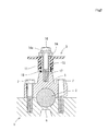
Fig. 1 is a vertical cross-sectional front view showing an embodiment of the present invention; -
Fig. 2 is a sectional view taken along lines II-II inFig. 1 ; and -
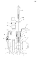
Fig. 3 is an exploded view. -
- 1
- cylinder head
- 2
- cam shaft
- 3
- head cover
- 5
- bearing portion
- 6
- bearing cap
- 8
- rotor
- 10
- cam angle sensor
- 11
- boss
- 12
- through-hole
- 14
- mounting portion
- 15
- collar
- 16
- fastening bolt
- Embodiments of the present invention will be described below with reference to
Figs. 1 to 3 . - In these figures, indicated by
reference sign 1 is a cylinder head of an internal combustion engine. Ahead cover 3 made of a synthetic resin is disposed above the upper face of thecylinder head 1 so as to cover acam shaft 2 pivotally supported on the upper face of the cylinder head. As conventionally known, thehead cover 3 is removably attached to thecylinder head 1 by fastening bolts (not shown), which are disposed at and penetrate through the periphery of the head cover. With the bolts tightened, aseal member 4 disposed under the periphery of the head cover is compressed. - The
cam shaft 2 on the upper face of thecylinder head 1 is rotatably supported by a bearingportion 5, formed integral with thecylinder head 1, and abearing cap 6 which is fastened to the bearingportion 5 with a pair ofbolts 7 for the right and left sides of the cap. Thecam shaft 2 is provided with arotor 8 adjacent to thebearing portion 5 and thebearing cap 6, where the rotor hasprojections 9 at phase positions where an intake valve or an exhaust valve is opened or closed. - Indicated by
reference sign 10 is a cam angle sensor. Thecam angle sensor 10 is inserted in a through-hole 12 in aboss 11 integrally formed in the syntheticresin head cover 3, such that an end of thecam angle sensor 10 can face theprojections 9 of therotor 8 of thecam shaft 2. Thecam angle sensor 10 is provided with aseal ring 13 around the outer circumferential surface, so that the seal ring is held in close contact with the inner circumferential surface of the through-hole 12. - The
cam angle sensor 10 is integrally provided with a mountingportion 14 at a position outside of thehead cover 3. - In the
boss 11 of thehead cover 3, acollar 15 made of a metal is fixed so as to penetrate through theboss 11 at a position right above thebearing cap 6. The lower end of thecollar 15 abuts the upper face of thebearing cap 6, while the upper end of thecollar 15 abuts the lower face of the mountingportion 14 of thecam angle sensor 10. - A headed
fastening bolt 16 is inserted in thecollar 15 through abolt hole 14a perforated in the mountingportion 14. The lower end of thefastening bolt 16 is screw-engaged with afemale thread 17 formed in thebearing cap 6 of thecylinder head 1, so that thefastening bolt 16 is tightened. Aseal member 18 having a ring shape surrounding the outer circumference of thecollar 15 is provided between the lower face of theboss 11 of thehead cover 3 and the upper face of thebearing cap 6. - In the above-described structure, the
cam angle sensor 10 can be securely mounted to thebearing cap 6 of thecylinder head 1, via themetal collar 15, by tightening thefastening bolt 16. Also, theboss 11 of thehead cover 3 and further a portion close to thecam angle sensor 10 can be pressed against thebearing cap 6 of thecylinder head 1, so that these portions are properly supported with suppressed vibration. - In addition, the
cam angle sensor 10 is simply inserted in the through-hole 12 of thehead cover 3 made of a synthetic resin. Thus, heat transmission from thecylinder head 1 to thecam angle sensor 10 is effectively suppressed. - In the foregoing embodiment, the
bearing cap 6 for pivotally supporting the upper half of thecam shaft 2 is used, among members of the cylinder head, for mounting thebearing cap 6. The present invention, however, is not limited to such a configuration. Another member formed integral with the cylinder head 1 (for example, the bearing portion 5) or a separate member attached to thecylinder head 1 may be adopted as "the member of the cylinder head" in the claims below for mounting thecam angle sensor 10.
Claims (6)
- A method of mounting a cam angle sensor in an internal combustion engine, the method comprising: inserting a cam angle sensor into a through-hole perforated through a head cover made of a synthetic resin for covering an upper face of a cylinder head, the cam angle sensor being provided for a cam shaft at the upper face of the cylinder head; and fastening a mounting portion integral with the cam angle sensor to a member of the cylinder head by using a fixing member penetrating through the head cover.
- The method according to claim 1, wherein the fixing member fastens simultaneously, to the member of the cylinder head, both the mounting portion of the cam angle sensor and a portion of the head cover through which the fixing member penetrates.
- The method according to claim 1 or 2, wherein a collar made of a metal is disposed at the portion of the head cover through which the fixing member penetrates in such a manner that the collar abuts the mounting portion of the cam angle sensor and the member of the cylinder head.
- A mounting device of a cam angle sensor in an internal combustion engine in which a head cover for covering a cam shaft at an upper face of a cylinder head is made of a synthetic resin,
wherein the cam angle sensor for the cam shaft is inserted in a through-hole perforated in the head cover, and a mounting portion integral with the cam angle sensor is fastened to a member of the cylinder head by a fixing member penetrating through the head cover. - The mounting device according to claim 4, wherein the fixing member fastens simultaneously, to the member of the cylinder head, both the mounting portion of the cam angle sensor and a portion of the head cover through which the fixing member penetrates.
- The mounting device according to claim 4 or 5, wherein a collar made of a metal is disposed at the portion of the head cover through which the fixing member penetrates in such a manner that the collar abuts the mounting portion of the cam angle sensor and the member of the cylinder head.
Applications Claiming Priority (2)
| Application Number | Priority Date | Filing Date | Title |
|---|---|---|---|
| JP2008162995A JP5171427B2 (en) | 2008-06-23 | 2008-06-23 | Cam angle sensor mounting apparatus for internal combustion engine |
| PCT/JP2009/060769 WO2009157323A1 (en) | 2008-06-23 | 2009-06-12 | Method and device for mounting cam angle sensor for internal combustion engine |
Publications (3)
| Publication Number | Publication Date |
|---|---|
| EP2314849A1 true EP2314849A1 (en) | 2011-04-27 |
| EP2314849A4 EP2314849A4 (en) | 2016-03-30 |
| EP2314849B1 EP2314849B1 (en) | 2018-11-14 |
Family
ID=41444392
Family Applications (1)
| Application Number | Title | Priority Date | Filing Date |
|---|---|---|---|
| EP09770033.0A Not-in-force EP2314849B1 (en) | 2008-06-23 | 2009-06-12 | Method and device for mounting cam angle sensor for internal combustion engine |
Country Status (6)
| Country | Link |
|---|---|
| US (1) | US9068528B2 (en) |
| EP (1) | EP2314849B1 (en) |
| JP (1) | JP5171427B2 (en) |
| CN (1) | CN102066726B (en) |
| MY (1) | MY156835A (en) |
| WO (1) | WO2009157323A1 (en) |
Cited By (2)
| Publication number | Priority date | Publication date | Assignee | Title |
|---|---|---|---|---|
| WO2015197410A1 (en) * | 2014-06-27 | 2015-12-30 | Polytec Plastics Germany Gmbh & Co. Kg | Cylinder head cover for a motor vehicle |
| US20220275770A1 (en) * | 2021-02-26 | 2022-09-01 | Mahle International Gmbh | Cylinder head cover |
Families Citing this family (14)
| Publication number | Priority date | Publication date | Assignee | Title |
|---|---|---|---|---|
| JP5278155B2 (en) * | 2009-05-07 | 2013-09-04 | トヨタ自動車株式会社 | Cylinder head cover |
| JP5806583B2 (en) * | 2011-10-19 | 2015-11-10 | 本田技研工業株式会社 | Overhead cam engine |
| JP6015599B2 (en) | 2013-08-30 | 2016-10-26 | アイシン精機株式会社 | Sensor support structure |
| JP6237175B2 (en) * | 2013-12-05 | 2017-11-29 | 三菱自動車工業株式会社 | engine |
| CN104234831B (en) * | 2014-06-25 | 2016-06-08 | 马勒技术投资(中国)有限公司 | Camshaft position transducer installation method |
| GB2533090A (en) * | 2014-12-08 | 2016-06-15 | Skf Ab | Sensor device with mounting means |
| JP6637357B2 (en) * | 2016-03-28 | 2020-01-29 | 本田技研工業株式会社 | Power unit |
| CN106271371A (en) * | 2016-08-25 | 2017-01-04 | 张家港清研再制造产业研究院有限公司 | A kind of engine cylinder-body spindle hole restorative procedure |
| CN106078077A (en) * | 2016-08-25 | 2016-11-09 | 张家港清研再制造产业研究院有限公司 | A kind of engine cylinder hole restorative procedure |
| US10590846B2 (en) | 2017-03-23 | 2020-03-17 | Caterpillar Inc. | Valve cover extension tube with integrated sensor |
| JP6916049B2 (en) * | 2017-06-22 | 2021-08-11 | 株式会社ミクニ | General-purpose engine |
| JP6528810B2 (en) * | 2017-07-14 | 2019-06-12 | マツダ株式会社 | Engine cylinder head cover structure |
| JP6863243B2 (en) * | 2017-11-15 | 2021-04-21 | トヨタ自動車株式会社 | Electronic device mounting mechanism |
| JP7040980B2 (en) * | 2018-03-29 | 2022-03-23 | 本田技研工業株式会社 | Internal combustion engine sensor mounting structure |
Family Cites Families (13)
| Publication number | Priority date | Publication date | Assignee | Title |
|---|---|---|---|---|
| JPH0868346A (en) * | 1994-08-26 | 1996-03-12 | Yamaha Motor Co Ltd | Engine angle sensor device |
| JP2913273B2 (en) * | 1996-04-17 | 1999-06-28 | 本田技研工業株式会社 | Engine rotation detector |
| US5987973A (en) * | 1996-07-24 | 1999-11-23 | Honda Giken Kogyo Kabushiki Kaisha | Rotation detecting device of an engine |
| JPH11257124A (en) | 1998-03-17 | 1999-09-21 | Suzuki Motor Corp | Thrust bearing structure of camshaft |
| JPH11324846A (en) * | 1998-05-11 | 1999-11-26 | Yamaha Motor Co Ltd | Internal combustion engine |
| JP2001329885A (en) * | 2000-05-18 | 2001-11-30 | Yamaha Motor Co Ltd | Engine cam angle sensor mounting structure |
| JP4248502B2 (en) * | 2005-01-07 | 2009-04-02 | トヨタ自動車株式会社 | Mounting structure of functional device for internal combustion engine |
| JP2006220073A (en) | 2005-02-10 | 2006-08-24 | Toyota Motor Corp | Sensor mounting structure and cam cap structure for internal combustion engine |
| JP4864548B2 (en) * | 2005-05-31 | 2012-02-01 | 株式会社東芝 | Medical report creation system, ultrasonic diagnostic apparatus incorporating the system, medical report creation program |
| JP4321504B2 (en) * | 2005-07-25 | 2009-08-26 | 日産自動車株式会社 | Cam angle sensor mounting structure for internal combustion engine |
| JP2007107387A (en) * | 2005-10-11 | 2007-04-26 | Mahle Filter Systems Japan Corp | Cam angle sensor mounting structure for internal combustion engine |
| ITMI20062289A1 (en) * | 2006-11-28 | 2008-05-29 | Iveco Spa | DEVICE FOR BRAKING FOR DECOMPRESSION IN ENDOTHERMIC ENGINES |
| JP2009167809A (en) * | 2008-01-10 | 2009-07-30 | Toyota Motor Corp | Sensor mounting method, mounting structure, and mounting bracket for internal combustion engine |
-
2008
- 2008-06-23 JP JP2008162995A patent/JP5171427B2/en active Active
-
2009
- 2009-06-12 US US13/000,474 patent/US9068528B2/en not_active Expired - Fee Related
- 2009-06-12 WO PCT/JP2009/060769 patent/WO2009157323A1/en not_active Ceased
- 2009-06-12 EP EP09770033.0A patent/EP2314849B1/en not_active Not-in-force
- 2009-06-12 CN CN200980123564.1A patent/CN102066726B/en not_active Expired - Fee Related
- 2009-06-12 MY MYPI2010006111A patent/MY156835A/en unknown
Non-Patent Citations (1)
| Title |
|---|
| See references of WO2009157323A1 * |
Cited By (3)
| Publication number | Priority date | Publication date | Assignee | Title |
|---|---|---|---|---|
| WO2015197410A1 (en) * | 2014-06-27 | 2015-12-30 | Polytec Plastics Germany Gmbh & Co. Kg | Cylinder head cover for a motor vehicle |
| US10208663B2 (en) | 2014-06-27 | 2019-02-19 | Polytec Plastics Germany Gmbh & Co. Kg | Cylinder head cover for a motor vehicle |
| US20220275770A1 (en) * | 2021-02-26 | 2022-09-01 | Mahle International Gmbh | Cylinder head cover |
Also Published As
| Publication number | Publication date |
|---|---|
| JP2010001856A (en) | 2010-01-07 |
| EP2314849A4 (en) | 2016-03-30 |
| WO2009157323A1 (en) | 2009-12-30 |
| CN102066726B (en) | 2015-05-06 |
| US20110119915A1 (en) | 2011-05-26 |
| US9068528B2 (en) | 2015-06-30 |
| JP5171427B2 (en) | 2013-03-27 |
| EP2314849B1 (en) | 2018-11-14 |
| CN102066726A (en) | 2011-05-18 |
| MY156835A (en) | 2016-03-31 |
Similar Documents
| Publication | Publication Date | Title |
|---|---|---|
| EP2314849A1 (en) | Method and device for mounting cam angle sensor for internal combustion engine | |
| JP2011001878A (en) | Camshaft device, engine with the same, and method for manufacturing camshaft device | |
| CN105715321B (en) | Composite cam bracket | |
| CN107023416B (en) | Protective cover structure of internal combustion engine | |
| JP2009209985A (en) | Sealing device in bolt for fastening synthetic resin-made enclosure | |
| JP2010031666A (en) | Engine cover | |
| EP2679792B1 (en) | Internal combustion engine head-cover structure | |
| US7975381B2 (en) | Valve operating camshaft system for internal combustion engine | |
| JP2010261361A (en) | Cylinder head cover | |
| JP5511721B2 (en) | Electronic component coupler protection device | |
| EP2818662B1 (en) | Engine | |
| EP1482149A1 (en) | Sensor mounting structure for engine | |
| JP6742744B2 (en) | Device for fixing at least one fuel injection nozzle | |
| JP6760010B2 (en) | Internal combustion engine | |
| US9650990B2 (en) | Seal retention assembly and a seal | |
| JP2002061549A (en) | Fuel pump mounting structure | |
| JP2007107387A (en) | Cam angle sensor mounting structure for internal combustion engine | |
| JP2004068822A (en) | Case member mounting structure | |
| JP2020060189A (en) | Cover structure of internal combustion engine | |
| JP2011070800A (en) | Protection device of coupler of electronic component | |
| JP6696893B2 (en) | Camshaft support member | |
| JP4923015B2 (en) | Electronically controlled industrial engine | |
| JP5062908B2 (en) | Electronically controlled engine | |
| JP2001342844A (en) | Harness holding member and maintenance cover for drive transmission mechanism case member | |
| JP2001234811A (en) | Cylinder head side cover having peep hole of 4-cycle ohc/ dohc engine for two-wheeler |
Legal Events
| Date | Code | Title | Description |
|---|---|---|---|
| PUAI | Public reference made under article 153(3) epc to a published international application that has entered the european phase |
Free format text: ORIGINAL CODE: 0009012 |
|
| 17P | Request for examination filed |
Effective date: 20110107 |
|
| AK | Designated contracting states |
Kind code of ref document: A1 Designated state(s): AT BE BG CH CY CZ DE DK EE ES FI FR GB GR HR HU IE IS IT LI LT LU LV MC MK MT NL NO PL PT RO SE SI SK TR |
|
| AX | Request for extension of the european patent |
Extension state: AL BA RS |
|
| RAP1 | Party data changed (applicant data changed or rights of an application transferred) |
Owner name: TOYOTA JIDOSHA KABUSHIKI KAISHA |
|
| DAX | Request for extension of the european patent (deleted) | ||
| RAP1 | Party data changed (applicant data changed or rights of an application transferred) |
Owner name: TOYOTA JIDOSHA KABUSHIKI KAISHA |
|
| RA4 | Supplementary search report drawn up and despatched (corrected) |
Effective date: 20160226 |
|
| RIC1 | Information provided on ipc code assigned before grant |
Ipc: F02D 35/00 20060101AFI20160222BHEP Ipc: F02F 1/24 20060101ALI20160222BHEP Ipc: F02F 7/00 20060101ALI20160222BHEP Ipc: F01L 1/04 20060101ALI20160222BHEP |
|
| GRAP | Despatch of communication of intention to grant a patent |
Free format text: ORIGINAL CODE: EPIDOSNIGR1 |
|
| STAA | Information on the status of an ep patent application or granted ep patent |
Free format text: STATUS: GRANT OF PATENT IS INTENDED |
|
| INTG | Intention to grant announced |
Effective date: 20180605 |
|
| GRAS | Grant fee paid |
Free format text: ORIGINAL CODE: EPIDOSNIGR3 |
|
| GRAA | (expected) grant |
Free format text: ORIGINAL CODE: 0009210 |
|
| STAA | Information on the status of an ep patent application or granted ep patent |
Free format text: STATUS: THE PATENT HAS BEEN GRANTED |
|
| AK | Designated contracting states |
Kind code of ref document: B1 Designated state(s): AT BE BG CH CY CZ DE DK EE ES FI FR GB GR HR HU IE IS IT LI LT LU LV MC MK MT NL NO PL PT RO SE SI SK TR |
|
| REG | Reference to a national code |
Ref country code: GB Ref legal event code: FG4D |
|
| REG | Reference to a national code |
Ref country code: CH Ref legal event code: EP Ref country code: AT Ref legal event code: REF Ref document number: 1065111 Country of ref document: AT Kind code of ref document: T Effective date: 20181115 |
|
| REG | Reference to a national code |
Ref country code: DE Ref legal event code: R096 Ref document number: 602009055665 Country of ref document: DE |
|
| REG | Reference to a national code |
Ref country code: IE Ref legal event code: FG4D |
|
| REG | Reference to a national code |
Ref country code: DE Ref legal event code: R084 Ref document number: 602009055665 Country of ref document: DE |
|
| REG | Reference to a national code |
Ref country code: GB Ref legal event code: 746 Effective date: 20181228 |
|
| REG | Reference to a national code |
Ref country code: NL Ref legal event code: MP Effective date: 20181114 |
|
| REG | Reference to a national code |
Ref country code: LT Ref legal event code: MG4D |
|
| REG | Reference to a national code |
Ref country code: AT Ref legal event code: MK05 Ref document number: 1065111 Country of ref document: AT Kind code of ref document: T Effective date: 20181114 |
|
| PG25 | Lapsed in a contracting state [announced via postgrant information from national office to epo] |
Ref country code: FI Free format text: LAPSE BECAUSE OF FAILURE TO SUBMIT A TRANSLATION OF THE DESCRIPTION OR TO PAY THE FEE WITHIN THE PRESCRIBED TIME-LIMIT Effective date: 20181114 Ref country code: IS Free format text: LAPSE BECAUSE OF FAILURE TO SUBMIT A TRANSLATION OF THE DESCRIPTION OR TO PAY THE FEE WITHIN THE PRESCRIBED TIME-LIMIT Effective date: 20190314 Ref country code: LV Free format text: LAPSE BECAUSE OF FAILURE TO SUBMIT A TRANSLATION OF THE DESCRIPTION OR TO PAY THE FEE WITHIN THE PRESCRIBED TIME-LIMIT Effective date: 20181114 Ref country code: AT Free format text: LAPSE BECAUSE OF FAILURE TO SUBMIT A TRANSLATION OF THE DESCRIPTION OR TO PAY THE FEE WITHIN THE PRESCRIBED TIME-LIMIT Effective date: 20181114 Ref country code: NO Free format text: LAPSE BECAUSE OF FAILURE TO SUBMIT A TRANSLATION OF THE DESCRIPTION OR TO PAY THE FEE WITHIN THE PRESCRIBED TIME-LIMIT Effective date: 20190214 Ref country code: BG Free format text: LAPSE BECAUSE OF FAILURE TO SUBMIT A TRANSLATION OF THE DESCRIPTION OR TO PAY THE FEE WITHIN THE PRESCRIBED TIME-LIMIT Effective date: 20190214 Ref country code: LT Free format text: LAPSE BECAUSE OF FAILURE TO SUBMIT A TRANSLATION OF THE DESCRIPTION OR TO PAY THE FEE WITHIN THE PRESCRIBED TIME-LIMIT Effective date: 20181114 Ref country code: ES Free format text: LAPSE BECAUSE OF FAILURE TO SUBMIT A TRANSLATION OF THE DESCRIPTION OR TO PAY THE FEE WITHIN THE PRESCRIBED TIME-LIMIT Effective date: 20181114 Ref country code: HR Free format text: LAPSE BECAUSE OF FAILURE TO SUBMIT A TRANSLATION OF THE DESCRIPTION OR TO PAY THE FEE WITHIN THE PRESCRIBED TIME-LIMIT Effective date: 20181114 |
|
| PG25 | Lapsed in a contracting state [announced via postgrant information from national office to epo] |
Ref country code: PT Free format text: LAPSE BECAUSE OF FAILURE TO SUBMIT A TRANSLATION OF THE DESCRIPTION OR TO PAY THE FEE WITHIN THE PRESCRIBED TIME-LIMIT Effective date: 20190314 Ref country code: SE Free format text: LAPSE BECAUSE OF FAILURE TO SUBMIT A TRANSLATION OF THE DESCRIPTION OR TO PAY THE FEE WITHIN THE PRESCRIBED TIME-LIMIT Effective date: 20181114 Ref country code: NL Free format text: LAPSE BECAUSE OF FAILURE TO SUBMIT A TRANSLATION OF THE DESCRIPTION OR TO PAY THE FEE WITHIN THE PRESCRIBED TIME-LIMIT Effective date: 20181114 Ref country code: GR Free format text: LAPSE BECAUSE OF FAILURE TO SUBMIT A TRANSLATION OF THE DESCRIPTION OR TO PAY THE FEE WITHIN THE PRESCRIBED TIME-LIMIT Effective date: 20190215 |
|
| PG25 | Lapsed in a contracting state [announced via postgrant information from national office to epo] |
Ref country code: CZ Free format text: LAPSE BECAUSE OF FAILURE TO SUBMIT A TRANSLATION OF THE DESCRIPTION OR TO PAY THE FEE WITHIN THE PRESCRIBED TIME-LIMIT Effective date: 20181114 Ref country code: PL Free format text: LAPSE BECAUSE OF FAILURE TO SUBMIT A TRANSLATION OF THE DESCRIPTION OR TO PAY THE FEE WITHIN THE PRESCRIBED TIME-LIMIT Effective date: 20181114 Ref country code: DK Free format text: LAPSE BECAUSE OF FAILURE TO SUBMIT A TRANSLATION OF THE DESCRIPTION OR TO PAY THE FEE WITHIN THE PRESCRIBED TIME-LIMIT Effective date: 20181114 Ref country code: IT Free format text: LAPSE BECAUSE OF FAILURE TO SUBMIT A TRANSLATION OF THE DESCRIPTION OR TO PAY THE FEE WITHIN THE PRESCRIBED TIME-LIMIT Effective date: 20181114 |
|
| REG | Reference to a national code |
Ref country code: DE Ref legal event code: R097 Ref document number: 602009055665 Country of ref document: DE |
|
| PG25 | Lapsed in a contracting state [announced via postgrant information from national office to epo] |
Ref country code: EE Free format text: LAPSE BECAUSE OF FAILURE TO SUBMIT A TRANSLATION OF THE DESCRIPTION OR TO PAY THE FEE WITHIN THE PRESCRIBED TIME-LIMIT Effective date: 20181114 Ref country code: RO Free format text: LAPSE BECAUSE OF FAILURE TO SUBMIT A TRANSLATION OF THE DESCRIPTION OR TO PAY THE FEE WITHIN THE PRESCRIBED TIME-LIMIT Effective date: 20181114 Ref country code: SK Free format text: LAPSE BECAUSE OF FAILURE TO SUBMIT A TRANSLATION OF THE DESCRIPTION OR TO PAY THE FEE WITHIN THE PRESCRIBED TIME-LIMIT Effective date: 20181114 |
|
| PLBE | No opposition filed within time limit |
Free format text: ORIGINAL CODE: 0009261 |
|
| STAA | Information on the status of an ep patent application or granted ep patent |
Free format text: STATUS: NO OPPOSITION FILED WITHIN TIME LIMIT |
|
| 26N | No opposition filed |
Effective date: 20190815 |
|
| PG25 | Lapsed in a contracting state [announced via postgrant information from national office to epo] |
Ref country code: SI Free format text: LAPSE BECAUSE OF FAILURE TO SUBMIT A TRANSLATION OF THE DESCRIPTION OR TO PAY THE FEE WITHIN THE PRESCRIBED TIME-LIMIT Effective date: 20181114 |
|
| PG25 | Lapsed in a contracting state [announced via postgrant information from national office to epo] |
Ref country code: MC Free format text: LAPSE BECAUSE OF FAILURE TO SUBMIT A TRANSLATION OF THE DESCRIPTION OR TO PAY THE FEE WITHIN THE PRESCRIBED TIME-LIMIT Effective date: 20181114 |
|
| REG | Reference to a national code |
Ref country code: CH Ref legal event code: PL |
|
| REG | Reference to a national code |
Ref country code: BE Ref legal event code: MM Effective date: 20190630 |
|
| PG25 | Lapsed in a contracting state [announced via postgrant information from national office to epo] |
Ref country code: TR Free format text: LAPSE BECAUSE OF FAILURE TO SUBMIT A TRANSLATION OF THE DESCRIPTION OR TO PAY THE FEE WITHIN THE PRESCRIBED TIME-LIMIT Effective date: 20181114 |
|
| PG25 | Lapsed in a contracting state [announced via postgrant information from national office to epo] |
Ref country code: IE Free format text: LAPSE BECAUSE OF NON-PAYMENT OF DUE FEES Effective date: 20190612 |
|
| PG25 | Lapsed in a contracting state [announced via postgrant information from national office to epo] |
Ref country code: CH Free format text: LAPSE BECAUSE OF NON-PAYMENT OF DUE FEES Effective date: 20190630 Ref country code: LU Free format text: LAPSE BECAUSE OF NON-PAYMENT OF DUE FEES Effective date: 20190612 Ref country code: LI Free format text: LAPSE BECAUSE OF NON-PAYMENT OF DUE FEES Effective date: 20190630 Ref country code: BE Free format text: LAPSE BECAUSE OF NON-PAYMENT OF DUE FEES Effective date: 20190630 |
|
| PG25 | Lapsed in a contracting state [announced via postgrant information from national office to epo] |
Ref country code: CY Free format text: LAPSE BECAUSE OF FAILURE TO SUBMIT A TRANSLATION OF THE DESCRIPTION OR TO PAY THE FEE WITHIN THE PRESCRIBED TIME-LIMIT Effective date: 20181114 |
|
| PG25 | Lapsed in a contracting state [announced via postgrant information from national office to epo] |
Ref country code: MT Free format text: LAPSE BECAUSE OF FAILURE TO SUBMIT A TRANSLATION OF THE DESCRIPTION OR TO PAY THE FEE WITHIN THE PRESCRIBED TIME-LIMIT Effective date: 20181114 Ref country code: HU Free format text: LAPSE BECAUSE OF FAILURE TO SUBMIT A TRANSLATION OF THE DESCRIPTION OR TO PAY THE FEE WITHIN THE PRESCRIBED TIME-LIMIT; INVALID AB INITIO Effective date: 20090612 |
|
| PGFP | Annual fee paid to national office [announced via postgrant information from national office to epo] |
Ref country code: DE Payment date: 20210518 Year of fee payment: 13 Ref country code: FR Payment date: 20210513 Year of fee payment: 13 |
|
| PGFP | Annual fee paid to national office [announced via postgrant information from national office to epo] |
Ref country code: GB Payment date: 20210520 Year of fee payment: 13 |
|
| PG25 | Lapsed in a contracting state [announced via postgrant information from national office to epo] |
Ref country code: MK Free format text: LAPSE BECAUSE OF FAILURE TO SUBMIT A TRANSLATION OF THE DESCRIPTION OR TO PAY THE FEE WITHIN THE PRESCRIBED TIME-LIMIT Effective date: 20181114 |
|
| REG | Reference to a national code |
Ref country code: DE Ref legal event code: R119 Ref document number: 602009055665 Country of ref document: DE |
|
| GBPC | Gb: european patent ceased through non-payment of renewal fee |
Effective date: 20220612 |
|
| PG25 | Lapsed in a contracting state [announced via postgrant information from national office to epo] |
Ref country code: FR Free format text: LAPSE BECAUSE OF NON-PAYMENT OF DUE FEES Effective date: 20220630 |
|
| PG25 | Lapsed in a contracting state [announced via postgrant information from national office to epo] |
Ref country code: GB Free format text: LAPSE BECAUSE OF NON-PAYMENT OF DUE FEES Effective date: 20220612 Ref country code: DE Free format text: LAPSE BECAUSE OF NON-PAYMENT OF DUE FEES Effective date: 20230103 |