EP2314477A1 - Vorrichtung zur visuellen Signalisierung einer Verzögerung - Google Patents
Vorrichtung zur visuellen Signalisierung einer Verzögerung Download PDFInfo
- Publication number
- EP2314477A1 EP2314477A1 EP09425415A EP09425415A EP2314477A1 EP 2314477 A1 EP2314477 A1 EP 2314477A1 EP 09425415 A EP09425415 A EP 09425415A EP 09425415 A EP09425415 A EP 09425415A EP 2314477 A1 EP2314477 A1 EP 2314477A1
- Authority
- EP
- European Patent Office
- Prior art keywords
- deceleration
- signaling
- acceleration
- signal
- visual signaling
- Prior art date
- Legal status (The legal status is an assumption and is not a legal conclusion. Google has not performed a legal analysis and makes no representation as to the accuracy of the status listed.)
- Withdrawn
Links
Images


Classifications
-
- B—PERFORMING OPERATIONS; TRANSPORTING
- B60—VEHICLES IN GENERAL
- B60Q—ARRANGEMENT OF SIGNALLING OR LIGHTING DEVICES, THE MOUNTING OR SUPPORTING THEREOF OR CIRCUITS THEREFOR, FOR VEHICLES IN GENERAL
- B60Q1/00—Arrangement of optical signalling or lighting devices, the mounting or supporting thereof or circuits therefor
- B60Q1/26—Arrangement of optical signalling or lighting devices, the mounting or supporting thereof or circuits therefor the devices being primarily intended to indicate the vehicle, or parts thereof, or to give signals, to other traffic
- B60Q1/44—Arrangement of optical signalling or lighting devices, the mounting or supporting thereof or circuits therefor the devices being primarily intended to indicate the vehicle, or parts thereof, or to give signals, to other traffic for indicating braking action or preparation for braking, e.g. by detection of the foot approaching the brake pedal
- B60Q1/444—Arrangement of optical signalling or lighting devices, the mounting or supporting thereof or circuits therefor the devices being primarily intended to indicate the vehicle, or parts thereof, or to give signals, to other traffic for indicating braking action or preparation for braking, e.g. by detection of the foot approaching the brake pedal with indication of the braking strength or speed changes, e.g. by changing shape or intensity of the indication
Definitions
- the technical reference field is that of the visual signaling used in the vehicles.
- the proposed device activates a visual signaling if the vehicle decelerates.
- the technique currently used in mass production vehicles warns of deceleration of the vehicle by a system connected to the brake pedal, that, if pressed, causes the lighting bodies at the back of the vehicles to be switched on.
- This signaling warns the driver in the vehicle behind of the imminent deceleration, to enable him to use precaution to avoid any contact between the two vehicles.
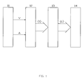
- the module marked with number 11, detection unit includes:
- the detection unit provides the processing unit with the acceleration value to be processed, signal A. If the number of transducers or their kind make it possible, it also provides the logical signal V which is related to the good functioning of transducers.
- the meaning of the logical signal V is the following:
- acceleration transducers ensures a better accuracy of acceleration signal and so a better reliability in the working of the overall system.
- processing units (12) acquires from the detection unit the acceleration signal A and its logical validity signal V, operates in the following way:
- processing units (12) acquires from the detection unit only the acceleration signal A, operates in the following way:
- the processing unit provides as output the set of bit ⁇ S ⁇ which in case of deceleration determines the signaling modes of lighting bodies regarding one or more of the following characteristics:
- the execution unit(13) receives the set ⁇ S ⁇ of bit from the processing unit which determines the signaling modes, and provides as output the set ⁇ L ⁇ of connection lines to the lighting bodies, to supply them with electrical power when the lighting conditions are verified.
- the signaling unit (14) is formed by the set of lighting bodies to which the execution unit supplies electric power in order to operate by complying to the signaling modes.
- the device needs two different power supplies.
- the 12V supply is given to the device from external power source while the 5V supply is obtained internally by the component 229, that receives 12V and gives a stabilized 5V.
- Components 203 and 236 are two capacitors respectively for the 12V supply and 5V supply.
- the components 201 and 202 are two acceleration transducers with the following characteristics:
- the voltage signals from the two transducers go through two low-pass filters:
- the filters are used to reduce possible noise, with frequency greater than a specific value, without affecting significantly the time response of the two transducers.
- the signals of the two transducers as outputs of respective filters are sent simultaneously to a differential amplifier, composed of the components 210, 211, 214, 215, 216 and 217, and to a circuit composed of the components 212, 213 and 218, that makes the average of the two signals.
- the comparator, the clipper and the not gate work as follows:
- the logic signal V for validity of the acceleration signal A is set to the logic level 0 and the led(component 227 of Fig.2 ) which signals the transducer malfunction will turn on.
- the gap is less than ⁇ g, the signal V is at 1 and the led is off.
- the analog signal A which is the average of the two transducers signal, and the logic signal V, that checks the A validity, respectively enter the analog input 235C and the digital input 235B of the microcontroller (component 235 on Fig. 2 ), which perform the function of the processing unit.
- the processing unit performs the following operation:
- the components 230, 231, 232, 234 realize the microcontroller reset either manually or at power on through the pin 235A of the device.
- the pin 235D and 235E of the microcontroller are used for its 5V power supply.
- the quartz, component 238, and the two capacitors, components 239 and 240, generate the microcontroller clock, and they are connected with it through 235F and 235G contacts.
- the microcontroller gives, related to the presentation modality, the digital output S1 and S0, that the execution unit made by the following components 237, 241, 242, 243, 244, 245, 246, 247, 248, 249, 250, 251, 252, 253, 254, 255 and 256, processes as follows:
- Diodes 254, 255 and 256 are necessary to avoid, once becoming in contact with lighting bodies, the device can take energy, loading external circuits.
- microcontroller program gives the voltage values on 235H and 235I contacts.
- the flow chart of operations, calculated by microcontroller, is in Fig. 3 .
- microcontroller start from setting up the input/output lines of microcontroller and setting default value to the variables (operation 301); following with conversion in digital form of the acceleration signal, that enters in analogical form through 235C microcontroller contact (operation 302). Then operation 303 checks V bit entering the microcontroller through the 235B contact:
- Fig. 5 shows horizontal and vertical projections
- Fig. 5 shows horizontal and vertical projections
- the very small dimensions enable a very different location choice; in this example the prototype was placed, as shown in Fig. 5 , on the rear part of the vehicle near the trunk.
- connection wires As shown on Fig. 5 components labeled with numbers from 501 to 507 are the connection wires, used as follow:
- Components 508 and 509 are the upper part and the lower part of the apparatus box. With labels 510 to 513 holes are shown to place screws for fixing the box to the vehicle structure.
- the described system can be used in the automobile industry field and in general in every means of transport whereas it is useful to extend the warning signaling modes to improve their safety.
Priority Applications (1)
| Application Number | Priority Date | Filing Date | Title |
|---|---|---|---|
| EP09425415A EP2314477A1 (de) | 2009-10-20 | 2009-10-20 | Vorrichtung zur visuellen Signalisierung einer Verzögerung |
Applications Claiming Priority (1)
| Application Number | Priority Date | Filing Date | Title |
|---|---|---|---|
| EP09425415A EP2314477A1 (de) | 2009-10-20 | 2009-10-20 | Vorrichtung zur visuellen Signalisierung einer Verzögerung |
Publications (2)
| Publication Number | Publication Date |
|---|---|
| EP2314477A1 true EP2314477A1 (de) | 2011-04-27 |
| EP2314477A8 EP2314477A8 (de) | 2011-09-14 |
Family
ID=42111329
Family Applications (1)
| Application Number | Title | Priority Date | Filing Date |
|---|---|---|---|
| EP09425415A Withdrawn EP2314477A1 (de) | 2009-10-20 | 2009-10-20 | Vorrichtung zur visuellen Signalisierung einer Verzögerung |
Country Status (1)
| Country | Link |
|---|---|
| EP (1) | EP2314477A1 (de) |
Cited By (2)
| Publication number | Priority date | Publication date | Assignee | Title |
|---|---|---|---|---|
| ITCZ20130002A1 (it) * | 2013-01-28 | 2014-07-29 | Pietro Arcidiacono | Sistema di segnalazione visiva dell'intensita' di frenata di un veicolo e relativo metodo di segnalazione |
| US9878658B2 (en) | 2013-03-15 | 2018-01-30 | Federal-Mogul Llc | Vehicle brake lighting |
Citations (7)
| Publication number | Priority date | Publication date | Assignee | Title |
|---|---|---|---|---|
| US4667177A (en) * | 1985-12-26 | 1987-05-19 | Athalye Ravindra G | Brake light signal system for a motor vehicle |
| DE19729784A1 (de) * | 1997-07-11 | 1998-01-15 | Wilhelm Dr Stork | Steuerung von Signaleinrichtungen an Fahrzeugen mittels Beschleunigungssensoren |
| EP0957000A2 (de) * | 1998-05-14 | 1999-11-17 | John Danny Newton | Progressive Bremsleuchtenverfahren |
| GB2351858A (en) * | 1999-07-07 | 2001-01-10 | Robert Keith Jordan | Vehicle deceleration indicator |
| DE10107720A1 (de) * | 2001-02-19 | 2003-10-16 | Kurt Spiegelmacher | Intelligentes System zur optischen Indikation der Bremsintensität von Kraftfahrzeugen bei Betätigung der Betriebsbremse |
| FR2905916A1 (fr) * | 2006-09-19 | 2008-03-21 | Denso Corp | Dispositif de commande d'activation de dispositif de protection |
| WO2008042200A2 (en) * | 2006-10-02 | 2008-04-10 | Cyberoptics Semiconductor, Inc. | Acceleration sensor with redundant accelerometers |
-
2009
- 2009-10-20 EP EP09425415A patent/EP2314477A1/de not_active Withdrawn
Patent Citations (7)
| Publication number | Priority date | Publication date | Assignee | Title |
|---|---|---|---|---|
| US4667177A (en) * | 1985-12-26 | 1987-05-19 | Athalye Ravindra G | Brake light signal system for a motor vehicle |
| DE19729784A1 (de) * | 1997-07-11 | 1998-01-15 | Wilhelm Dr Stork | Steuerung von Signaleinrichtungen an Fahrzeugen mittels Beschleunigungssensoren |
| EP0957000A2 (de) * | 1998-05-14 | 1999-11-17 | John Danny Newton | Progressive Bremsleuchtenverfahren |
| GB2351858A (en) * | 1999-07-07 | 2001-01-10 | Robert Keith Jordan | Vehicle deceleration indicator |
| DE10107720A1 (de) * | 2001-02-19 | 2003-10-16 | Kurt Spiegelmacher | Intelligentes System zur optischen Indikation der Bremsintensität von Kraftfahrzeugen bei Betätigung der Betriebsbremse |
| FR2905916A1 (fr) * | 2006-09-19 | 2008-03-21 | Denso Corp | Dispositif de commande d'activation de dispositif de protection |
| WO2008042200A2 (en) * | 2006-10-02 | 2008-04-10 | Cyberoptics Semiconductor, Inc. | Acceleration sensor with redundant accelerometers |
Cited By (3)
| Publication number | Priority date | Publication date | Assignee | Title |
|---|---|---|---|---|
| ITCZ20130002A1 (it) * | 2013-01-28 | 2014-07-29 | Pietro Arcidiacono | Sistema di segnalazione visiva dell'intensita' di frenata di un veicolo e relativo metodo di segnalazione |
| WO2014115021A1 (en) | 2013-01-28 | 2014-07-31 | Pietro Arcidiacono | System for visual signaling the intensity of braking of a vehicle and relative method |
| US9878658B2 (en) | 2013-03-15 | 2018-01-30 | Federal-Mogul Llc | Vehicle brake lighting |
Also Published As
| Publication number | Publication date |
|---|---|
| EP2314477A8 (de) | 2011-09-14 |
Similar Documents
| Publication | Publication Date | Title |
|---|---|---|
| US11518298B2 (en) | High visibility lighting for autonomous vehicles | |
| US9878658B2 (en) | Vehicle brake lighting | |
| CN103818306A (zh) | 汽车雾灯、远近光、危险警报灯和紧急救援自动控制系统 | |
| EP2314477A1 (de) | Vorrichtung zur visuellen Signalisierung einer Verzögerung | |
| CN105365670A (zh) | 一种基于光线检测的车用灯光控制提醒装置及其控制方法 | |
| CN103241165B (zh) | 雾灯控制系统 | |
| US5353007A (en) | Automotive turn signal warning device | |
| CN205365391U (zh) | 一种汽车前照灯未开提醒装置 | |
| US20040032324A1 (en) | Brake light controller | |
| US4871945A (en) | Automatic brake light flashing electric module and circuit | |
| EP2948343B1 (de) | System zur visuellen signalisierung der bremsintensität eines fahrzeugs und entsprechendes verfahren | |
| CN110539830A (zh) | 一种电动车灯光控制系统 | |
| KR200445833Y1 (ko) | 자동차 보조등 제어회로 | |
| CN203623509U (zh) | 闪烁的汽车led警示灯 | |
| US20210086853A1 (en) | Trailer Lighting Activation Device | |
| KR100683250B1 (ko) | 차량용 비상스위치의 동작 표시장치 | |
| KR0182989B1 (ko) | 차량의 도어열림 경고장치 | |
| CN102874118B (zh) | 一种自动判断仪表车速信号来源的装置及其判断方法 | |
| KR100187471B1 (ko) | 주차 브레이크 경보장치 | |
| KR100478364B1 (ko) | 자동차 lan 시스템에 장착되는 인패널 ecu | |
| WO2022241025A1 (en) | High visibility lighting for autonomous vehicles | |
| CA1339282C (en) | Automatic brake light flashing electric module and circuit | |
| KR0157374B1 (ko) | 자동차의 비상램프 점등시 방향전환 지시장치 | |
| KR970006289Y1 (ko) | 자동차의 방향전환 및 정지표시장치 | |
| KR20050082185A (ko) | 자동차 전조등 자동제어 |
Legal Events
| Date | Code | Title | Description |
|---|---|---|---|
| PUAI | Public reference made under article 153(3) epc to a published international application that has entered the european phase |
Free format text: ORIGINAL CODE: 0009012 |
|
| AK | Designated contracting states |
Kind code of ref document: A1 Designated state(s): AT BE BG CH CY CZ DE DK EE ES FI FR GB GR HR HU IE IS IT LI LT LU LV MC MK MT NL NO PL PT RO SE SI SK SM TR |
|
| AX | Request for extension of the european patent |
Extension state: AL BA RS |
|
| 17P | Request for examination filed |
Effective date: 20110603 |
|
| 17Q | First examination report despatched |
Effective date: 20110812 |
|
| RIN1 | Information on inventor provided before grant (corrected) |
Inventor name: ARCIDIACONO, PIETRO |
|
| RAP1 | Party data changed (applicant data changed or rights of an application transferred) |
Owner name: ARCIDIACONO, PIETRO |
|
| RIN1 | Information on inventor provided before grant (corrected) |
Inventor name: ARCIDIACONO, PIETRO |
|
| STAA | Information on the status of an ep patent application or granted ep patent |
Free format text: STATUS: THE APPLICATION HAS BEEN WITHDRAWN |
|
| 18W | Application withdrawn |
Effective date: 20121107 |