EP2314402A2 - Method of forming a metal matrix component - Google Patents
Method of forming a metal matrix component Download PDFInfo
- Publication number
- EP2314402A2 EP2314402A2 EP20100191926 EP10191926A EP2314402A2 EP 2314402 A2 EP2314402 A2 EP 2314402A2 EP 20100191926 EP20100191926 EP 20100191926 EP 10191926 A EP10191926 A EP 10191926A EP 2314402 A2 EP2314402 A2 EP 2314402A2
- Authority
- EP
- European Patent Office
- Prior art keywords
- pulley
- metal
- metal material
- crankshaft damper
- damper
- Prior art date
- Legal status (The legal status is an assumption and is not a legal conclusion. Google has not performed a legal analysis and makes no representation as to the accuracy of the status listed.)
- Withdrawn
Links
Images


Classifications
-
- F—MECHANICAL ENGINEERING; LIGHTING; HEATING; WEAPONS; BLASTING
- F16—ENGINEERING ELEMENTS AND UNITS; GENERAL MEASURES FOR PRODUCING AND MAINTAINING EFFECTIVE FUNCTIONING OF MACHINES OR INSTALLATIONS; THERMAL INSULATION IN GENERAL
- F16F—SPRINGS; SHOCK-ABSORBERS; MEANS FOR DAMPING VIBRATION
- F16F15/00—Suppression of vibrations in systems; Means or arrangements for avoiding or reducing out-of-balance forces, e.g. due to motion
- F16F15/10—Suppression of vibrations in rotating systems by making use of members moving with the system
- F16F15/12—Suppression of vibrations in rotating systems by making use of members moving with the system using elastic members or friction-damping members, e.g. between a rotating shaft and a gyratory mass mounted thereon
- F16F15/121—Suppression of vibrations in rotating systems by making use of members moving with the system using elastic members or friction-damping members, e.g. between a rotating shaft and a gyratory mass mounted thereon using springs as elastic members, e.g. metallic springs
- F16F15/124—Elastomeric springs
- F16F15/126—Elastomeric springs consisting of at least one annular element surrounding the axis of rotation
-
- B—PERFORMING OPERATIONS; TRANSPORTING
- B22—CASTING; POWDER METALLURGY
- B22F—WORKING METALLIC POWDER; MANUFACTURE OF ARTICLES FROM METALLIC POWDER; MAKING METALLIC POWDER; APPARATUS OR DEVICES SPECIALLY ADAPTED FOR METALLIC POWDER
- B22F8/00—Manufacture of articles from scrap or waste metal particles
-
- C—CHEMISTRY; METALLURGY
- C22—METALLURGY; FERROUS OR NON-FERROUS ALLOYS; TREATMENT OF ALLOYS OR NON-FERROUS METALS
- C22C—ALLOYS
- C22C32/00—Non-ferrous alloys containing at least 5% by weight but less than 50% by weight of oxides, carbides, borides, nitrides, silicides or other metal compounds, e.g. oxynitrides, sulfides, whether added as such or formed in situ
- C22C32/0094—Non-ferrous alloys containing at least 5% by weight but less than 50% by weight of oxides, carbides, borides, nitrides, silicides or other metal compounds, e.g. oxynitrides, sulfides, whether added as such or formed in situ with organic materials as the main non-metallic constituent, e.g. resin
-
- F—MECHANICAL ENGINEERING; LIGHTING; HEATING; WEAPONS; BLASTING
- F16—ENGINEERING ELEMENTS AND UNITS; GENERAL MEASURES FOR PRODUCING AND MAINTAINING EFFECTIVE FUNCTIONING OF MACHINES OR INSTALLATIONS; THERMAL INSULATION IN GENERAL
- F16F—SPRINGS; SHOCK-ABSORBERS; MEANS FOR DAMPING VIBRATION
- F16F15/00—Suppression of vibrations in systems; Means or arrangements for avoiding or reducing out-of-balance forces, e.g. due to motion
- F16F15/22—Compensation of inertia forces
-
- F—MECHANICAL ENGINEERING; LIGHTING; HEATING; WEAPONS; BLASTING
- F16—ENGINEERING ELEMENTS AND UNITS; GENERAL MEASURES FOR PRODUCING AND MAINTAINING EFFECTIVE FUNCTIONING OF MACHINES OR INSTALLATIONS; THERMAL INSULATION IN GENERAL
- F16F—SPRINGS; SHOCK-ABSORBERS; MEANS FOR DAMPING VIBRATION
- F16F15/00—Suppression of vibrations in systems; Means or arrangements for avoiding or reducing out-of-balance forces, e.g. due to motion
- F16F15/30—Flywheels
-
- B—PERFORMING OPERATIONS; TRANSPORTING
- B22—CASTING; POWDER METALLURGY
- B22F—WORKING METALLIC POWDER; MANUFACTURE OF ARTICLES FROM METALLIC POWDER; MAKING METALLIC POWDER; APPARATUS OR DEVICES SPECIALLY ADAPTED FOR METALLIC POWDER
- B22F2998/00—Supplementary information concerning processes or compositions relating to powder metallurgy
- B22F2998/10—Processes characterised by the sequence of their steps
-
- Y—GENERAL TAGGING OF NEW TECHNOLOGICAL DEVELOPMENTS; GENERAL TAGGING OF CROSS-SECTIONAL TECHNOLOGIES SPANNING OVER SEVERAL SECTIONS OF THE IPC; TECHNICAL SUBJECTS COVERED BY FORMER USPC CROSS-REFERENCE ART COLLECTIONS [XRACs] AND DIGESTS
- Y02—TECHNOLOGIES OR APPLICATIONS FOR MITIGATION OR ADAPTATION AGAINST CLIMATE CHANGE
- Y02P—CLIMATE CHANGE MITIGATION TECHNOLOGIES IN THE PRODUCTION OR PROCESSING OF GOODS
- Y02P10/00—Technologies related to metal processing
- Y02P10/20—Recycling
-
- Y—GENERAL TAGGING OF NEW TECHNOLOGICAL DEVELOPMENTS; GENERAL TAGGING OF CROSS-SECTIONAL TECHNOLOGIES SPANNING OVER SEVERAL SECTIONS OF THE IPC; TECHNICAL SUBJECTS COVERED BY FORMER USPC CROSS-REFERENCE ART COLLECTIONS [XRACs] AND DIGESTS
- Y02—TECHNOLOGIES OR APPLICATIONS FOR MITIGATION OR ADAPTATION AGAINST CLIMATE CHANGE
- Y02W—CLIMATE CHANGE MITIGATION TECHNOLOGIES RELATED TO WASTEWATER TREATMENT OR WASTE MANAGEMENT
- Y02W30/00—Technologies for solid waste management
- Y02W30/50—Reuse, recycling or recovery technologies
-
- Y—GENERAL TAGGING OF NEW TECHNOLOGICAL DEVELOPMENTS; GENERAL TAGGING OF CROSS-SECTIONAL TECHNOLOGIES SPANNING OVER SEVERAL SECTIONS OF THE IPC; TECHNICAL SUBJECTS COVERED BY FORMER USPC CROSS-REFERENCE ART COLLECTIONS [XRACs] AND DIGESTS
- Y10—TECHNICAL SUBJECTS COVERED BY FORMER USPC
- Y10T—TECHNICAL SUBJECTS COVERED BY FORMER US CLASSIFICATION
- Y10T29/00—Metal working
- Y10T29/14—Shredding metal or metal wool article making
-
- Y—GENERAL TAGGING OF NEW TECHNOLOGICAL DEVELOPMENTS; GENERAL TAGGING OF CROSS-SECTIONAL TECHNOLOGIES SPANNING OVER SEVERAL SECTIONS OF THE IPC; TECHNICAL SUBJECTS COVERED BY FORMER USPC CROSS-REFERENCE ART COLLECTIONS [XRACs] AND DIGESTS
- Y10—TECHNICAL SUBJECTS COVERED BY FORMER USPC
- Y10T—TECHNICAL SUBJECTS COVERED BY FORMER US CLASSIFICATION
- Y10T29/00—Metal working
- Y10T29/49—Method of mechanical manufacture
- Y10T29/49453—Pulley making
- Y10T29/49455—Assembly
-
- Y—GENERAL TAGGING OF NEW TECHNOLOGICAL DEVELOPMENTS; GENERAL TAGGING OF CROSS-SECTIONAL TECHNOLOGIES SPANNING OVER SEVERAL SECTIONS OF THE IPC; TECHNICAL SUBJECTS COVERED BY FORMER USPC CROSS-REFERENCE ART COLLECTIONS [XRACs] AND DIGESTS
- Y10—TECHNICAL SUBJECTS COVERED BY FORMER USPC
- Y10T—TECHNICAL SUBJECTS COVERED BY FORMER US CLASSIFICATION
- Y10T29/00—Metal working
- Y10T29/49—Method of mechanical manufacture
- Y10T29/49751—Scrap recovering or utilizing
- Y10T29/49753—Metalworking to consolidate scrap
-
- Y—GENERAL TAGGING OF NEW TECHNOLOGICAL DEVELOPMENTS; GENERAL TAGGING OF CROSS-SECTIONAL TECHNOLOGIES SPANNING OVER SEVERAL SECTIONS OF THE IPC; TECHNICAL SUBJECTS COVERED BY FORMER USPC CROSS-REFERENCE ART COLLECTIONS [XRACs] AND DIGESTS
- Y10—TECHNICAL SUBJECTS COVERED BY FORMER USPC
- Y10T—TECHNICAL SUBJECTS COVERED BY FORMER US CLASSIFICATION
- Y10T74/00—Machine element or mechanism
- Y10T74/21—Elements
- Y10T74/2121—Flywheel, motion smoothing-type
- Y10T74/2131—Damping by absorbing vibration force [via rubber, elastomeric material, etc.]
Definitions
- the invention relates to a method of forming a metal matrix component, and more particularly to a method of forming a metal matrix component by use of scrap metal material that is compacted and bound together by an adhesive.
- crankshaft damper pulleys are conventionally made by spinning sheet metal using a number of different processes known in the industry.
- the mass of the crankshaft damper pulley must be greater than that provided by ordinary sheet metal pulleys. Greater mass is required to give the required amount of inertia' to damps crankshaft vibrations.
- Machining the pulley grooves also cuts through the grains, creating a weaker structure than spinning or flow forming which flows the grain structure and also reduces the grain size and crystalline dislocation, creating a much stronger part. This is also referred to as work hardening.
- flow formed sheet metal parts can only be made to a certain thickness both economically and practically. This limit is up to about 5 mm of sheet metal thickness.
- the primary aspect of the invention is to provide a method of forming a metal matrix component and product using scrap metal material that is compacted and bound together by an adhesive.
- the invention comprises a method of forming a metal matrix component and product that comprises forming scrap sheet metal material, shredding the scrap sheet metal material to a predetermined size range, filling the shredded scrap sheet metal material into a compacting die, adding an adhesive material to the shredded scrap sheet metal material in the compacting die, compressing the shredded scrap sheet metal material and curing the adhesive to form a metal matrix component.
- the invention comprises a metal matrix component, such as an inertia ring, that can be used in a product such as a damper pulley.
- a metal matrix component such as an inertia ring
- the damper pulley utilizing the metal matrix component has all of the required physical attributes including sufficient inertia and strength present in prior art damper pulleys, but is less costly to manufacture.
- the invention utilizes scrap metal material that is a by-product of a metal manufacturing process, for example, as a by-product of a sheet metal pulley manufacturing process.
- the inventive process can be used to manufacture a component that can be used in a primary or secondary crankshaft damper.
- a primary damper comprises a pulley with an inertia ring attached to the pulley by way of a damping member.
- the pulley and hub are a rigid structure.
- a secondary damper comprises a pulley and inertia ring which is bound to a hub only through an elastomeric damping member.
- the primary or secondary damper is attached to an engine crankshaft to damp crankshaft vibrations.
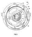
- Fig. 1 is a front elevation view of a secondary crankshaft damper.
- Crankshaft damper 100 comprises a hub 10 which is engaged with a combined pulley/inertia ring 20 through an elastomeric damper member 30. Damper member 30 is disposed between the hub and pulley/inertia ring.
- the elastomeric damper member 30 is used to damp internal combustion engine crankshaft vibrations.
- the damper is connected to an engine crankshaft through hub portion 11 using fasteners known in the art such a screw or bolt.
- pulley/inertia ring 20 initially comprises a round sheet metal blank that is cut or stamped from a coil and is subsequently spun formed to form a pulley as desired, see Fig. 4 .
- Methods of spin forming round sheet metal blanks into various shapes and forms are well known in the art.
- Fig. 2 is a cross-sectional view of an inventive crankshaft damper.
- the process uses stamped sheet steel to make a damper pulley of suitable inertia.
- the scrap steel generated from the sheet steel stamping process used to make the pulley namely, during cutting a round blank from a steel coil strip, is reused to make the inertia ring component 22a.
- Receiving portion 220 in sheet metal portion 20b receives component 22a.
- Component 22a comprises inertia substantially equivalent to a component made of cast iron or steel.
- the inventive process comprises the following steps:
- crankshaft damper having a metal matrix component with suitably high inertia that is much less expensive than crankshaft dampers having cast iron inertia rings while possessing many superior technical advantages.
- the stamping and spinning process may also be used to fabricate the hub for the crankshaft damper. This results in the hub and the pulley being fabricated of sheet metal by stamping and spinning, while the metal matrix component inertia ring is fabricated using the scrap metal material derived from the fabrication of the hub and/or pulley, or other metal scrap waste stream.
- the scrap metal material may be obtained from other than the hub and pulley fabrication process, but, using the hub and pulley fabrication scrap material waste stream allows the cost savings and technical advantages to be fully realized over the prior art processes.
- suitable adhesives include, but are not limited, to cyanoacrylate adhesives, epoxy adhesives, acrylic adhesives, polyurethane adhesives, nylon resins, and phenolic resin which is a thermoset resin. All of the foregoing known adhesives are cured using known methods and processes.
- a class of elastomers called “self-bonding” or “self-stick” that do not require adhesives for bonding to metals may be used to bond through oily metal surfaces while generating a very high bonding force, while also protecting the particles from corrosion permanently.
- Self-bonding or self-stick elastomers are formulated to bond to metals in their curing stage without the use of adhesives. They become “self-stick” by adding adhesion promoters to the compound formulas.
- Some common elastomers that can be made self-stick by adding adhesion promoters to their mix include VAMAC, EVM, ACM and Butyl.
- Adhesion promoters include zinc acrylates (ZDMA, ZDA) and Ricobond (MAM).
- elastomers for member 30 which are all thermoset types.
- Thermoplastics may be used as well.
- suitable elastomers include natural rubber, EPDM, butyl, VAMAC ® , polyurethane, HNBR, silicone Rubber and EVM.
- the scrap material utilized in the inventive process may comprise any form of metallic material that may be used in the production of any metal product including but not limited to crankshaft damper inertia rings and pulleys. These include but are not limited to all forms of steels, including stainless steels, as well as aluminum. Of course, non-steel metallic materials such as bronze, iron, copper and so on may be used as the shredded metal material since the material only needs to be subject to being compacted, compatible with the adhesives, and have a sufficient mass to provide the necessary inertial characteristics. Hence, any suitable metal side stream from other manufacturing lines may be used to manufacture the shredded metal material metal matrix components. In addition non-metallic materials such as gravel, sand, crushed rock, glasses or other materials having a specific gravity greater than one (1) may be used.
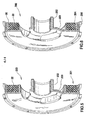
- Fig. 5 is a cross-sectional view of a crankshaft damper 200 which depicts the shredded scrap metal material component 22 after having been poured into a cavity or receiving portion 201.
- adhesive is then added to the sheet metal material in the cavity.
- the adhesive is then cured to bond component 22 to the pulley. In this embodiment it is not necessary to compress the material. Further, the adhesive may be added to material 22a before it is poured into the cavity.
- component 22 in a fully compressed state as described in steps "a” thru “f", is pressed into cavity 201.
- Damper or pulley 200 also comprises a hub 202 and web 203.
- a fully compressed component 22 as formed in steps "a" thru “f” is pressed into and bonded to elastomeric member 30 using an adhesive as described elsewhere in this specification.
- no cavity is formed to receive component 22.
- its diameter is selected so that it gives a slight interference fit with the inner surface 204 of elastomeric member 30.
- Elastomeric member 30 is bonded using adhesives described herein to the inner surface 205 of the pulley.
- Component 22 may also be pressed against web 203 for added stability, but, it is not bonded to the web in order for component 22 to have freedom of movement as it damps vibrations.
- the adhesive is cured once component 22 is pressed into place.
- pulley 200 and 300 are each formed using spin forming processes described elsewhere in this specification.
- Net-shaped refers to a completed part which has no further need for further machining to clean up dimensional variances, essentially producing a finished product.
- Advantages of the invention include a lower relative cost than a cast iron machined inertia ring because purchased material is reused and fewer manufacturing steps are required.
- the spun formed grooves are stronger than cut grooves of castings because the spin forming process flows the material grains in the ribbed portion 210, see Fig. 2 , rather than cutting through them in the machining process.
- work hardening resulting from flow forming improves the strength of formed pulleys.
- the inventive pulleys promote longer belt life due to the smoother surface finish of the formed metal.
- the inventive process pulleys also lack surface porosities which can initiate corrosion related failures. Further, utilization of metal scrap results in an environmentally responsive manufacturing by avoiding the expenditure of more energy (fuel) that would otherwise be used to reprocess the scrap at a mill.
- the product manufactured using the inventive process can be used to produce automotive and non-automotive crankshaft dampers. It can also be used in any other application where a metal matrix, high inertia, rotating or non-rotating component is required.
- the inventive process can also use scrap metal to manufacture many products that require high mass, net- shape components at a lower cost through simpler processing and a more environmentally friendly manner than using virgin raw materials.
- the inventive process achieves this goal without recycling the material to its raw form.
Abstract
Description
- The invention relates to a method of forming a metal matrix component, and more particularly to a method of forming a metal matrix component by use of scrap metal material that is compacted and bound together by an adhesive.
- Automotive pulleys are conventionally made by spinning sheet metal using a number of different processes known in the industry. However, for crankshaft dampers, in many cases the mass of the crankshaft damper pulley must be greater than that provided by ordinary sheet metal pulleys. Greater mass is required to give the required amount of inertia' to damps crankshaft vibrations.
- Conventionally, greater mass is achieved by using a cast iron pulley instead of a spun sheet metal pulley. The problem with cast iron is that due to its manufacturing process, i.e., casting in sand, it has to be machined to achieve the desired net shape. Machining is an expensive operation. In addition, machined grooves for a multi-ribbed pulley have a higher surface roughness than a spun part due to the existence of machining marks, namely, grooves. Furthermore, machining exposes porosities which are inherent in the iron casting. The sharp edges of the exposed porosities are detrimental to a belt running in the pulley grooves.
- Machining the pulley grooves also cuts through the grains, creating a weaker structure than spinning or flow forming which flows the grain structure and also reduces the grain size and crystalline dislocation, creating a much stronger part. This is also referred to as work hardening.
- Further, flow formed sheet metal parts can only be made to a certain thickness both economically and practically. This limit is up to about 5 mm of sheet metal thickness.
- Methods are known for utilizing scrap in the recycling of materials to their raw state, but not to manufacture durable, functional, and net-shaped products.
- Representative of the art is
U.S. patent no. 4,585,475 to Fosnacht (1986 ) which discloses a method for recycling oily mill scale. - What is needed is a method of forming a metal matrix component and product using scrap metal material that is compacted and bound together by an adhesive. The present invention meets this need.
- The primary aspect of the invention is to provide a method of forming a metal matrix component and product using scrap metal material that is compacted and bound together by an adhesive.
- Other aspects of the invention will be pointed out or made obvious by the following description of the invention and the accompanying drawings.
- The invention comprises a method of forming a metal matrix component and product that comprises forming scrap sheet metal material, shredding the scrap sheet metal material to a predetermined size range, filling the shredded scrap sheet metal material into a compacting die, adding an adhesive material to the shredded scrap sheet metal material in the compacting die, compressing the shredded scrap sheet metal material and curing the adhesive to form a metal matrix component.
- The accompanying drawings, which are incorporated in and form a part of the specification, illustrate preferred embodiments of the present invention, and together with a description, serve to explain the principles of the invention.
-
Fig. 1 is a front elevation view of a secondary crankshaft damper. -
Fig. 2 is a cross-sectional view of the crankshaft damper inFig. 1 . -
Fig. 3 is a perspective view of a compacting die. -
Fig. 4 is a plan view of a sheet metal strip with pulley blanks stamped out. -
Fig. 5 is a cross-sectional view of a crankshaft damper. -
Fig. 6 is a cross-sectional view of a crankshaft damper. - The invention comprises a metal matrix component, such as an inertia ring, that can be used in a product such as a damper pulley. The damper pulley utilizing the metal matrix component has all of the required physical attributes including sufficient inertia and strength present in prior art damper pulleys, but is less costly to manufacture.
- The invention utilizes scrap metal material that is a by-product of a metal manufacturing process, for example, as a by-product of a sheet metal pulley manufacturing process. The inventive process can be used to manufacture a component that can be used in a primary or secondary crankshaft damper.
- A primary damper comprises a pulley with an inertia ring attached to the pulley by way of a damping member. The pulley and hub are a rigid structure.
- A secondary damper comprises a pulley and inertia ring which is bound to a hub only through an elastomeric damping member. The primary or secondary damper is attached to an engine crankshaft to damp crankshaft vibrations.
-
Fig. 1 is a front elevation view of a secondary crankshaft damper.Crankshaft damper 100 comprises ahub 10 which is engaged with a combined pulley/inertia ring 20 through anelastomeric damper member 30. Dampermember 30 is disposed between the hub and pulley/inertia ring. - The
elastomeric damper member 30 is used to damp internal combustion engine crankshaft vibrations. The damper is connected to an engine crankshaft throughhub portion 11 using fasteners known in the art such a screw or bolt. - During fabrication of the crankshaft damper, pulley/
inertia ring 20 initially comprises a round sheet metal blank that is cut or stamped from a coil and is subsequently spun formed to form a pulley as desired, seeFig. 4 . Methods of spin forming round sheet metal blanks into various shapes and forms are well known in the art. - During the cutting or stamping process a waste stream of sheet metal material representing approximately 25% offal is scraped and ultimately sold to mills for remelting at a relatively low cost. To reduce or eliminate this significant waste stream, the instant inventive process fully utilizes this suitable but previously unused scrap material.
-
Fig. 2 is a cross-sectional view of an inventive crankshaft damper. The process uses stamped sheet steel to make a damper pulley of suitable inertia. The scrap steel generated from the sheet steel stamping process used to make the pulley, namely, during cutting a round blank from a steel coil strip, is reused to make theinertia ring component 22a. Receivingportion 220 insheet metal portion 20b receivescomponent 22a.Component 22a comprises inertia substantially equivalent to a component made of cast iron or steel. - The inventive process comprises the following steps:
- a) A sheet metal blank is stamped or cut from a sheet metal coil strip. The sheet metal blank is flow formed or spun formed using known methods to form pulley/inertia ring
sheet metal portion 20b. The inventive process may be used in the fabrication of any rotating component in addition to a pulley or hub and therefore is not limited to the description given here. Areceiving portion 220 is formed in the pulley/inertia ring portion 20b to receive themetal matrix component 22a.Portion 21 comprises amulti-ribbed profile 210 for engaging a multi-ribbed belt. Scrap steel material is created as a result of the stamping or cutting process.Fig. 4 is a plan view of asheet metal strip 400 withpulley blanks 401 stamped out.Scrap metal material 402, "offal", is generated in all stamping processes where a round, arcuate or otherwise non-rectangular part (for example a pulley, damper, gear, cap, etc.) is stamped from the strip of sheet or plate metal. The offal usually represents approximately 20 to 25% of the virgin sheet metal strip material, although this amount can vary according to the shape of the part being stamped or cut. The offal is traditionally sent back to steel mills to be recycled by melting. - b) The
scrap metal material 402 from step "a" is shredded using known processes to form particles having a predetermined size in the range of, for example, approximately 2 mm to 4 mm, although this range may be varied to include approximately +0mm up to approximately 6mm particles. The dimensions are offered only as examples since the shredded material does not have to be dimensionally homogeneous and can vary in size and volume so as long as the shredded metal particles are not too long or too wide for the intended component. Hence, the appropriate particle size is ultimately determined by the size and shape of the part to be fabricated using the inventive process. Once the shredded scrap metal material is formed it may be used in a number of different embodiments. In an alternate embodiment the metal material may be obtained from any source so long as the metal material has the requisite size. This includes metal material purpose produced for this application. However, the greatest benefit of the invention is realized by using metal material from the related fabrication waste stream. - c) Once formed, the shredded scrap metal material is weighed and filled into a compacting die, for example using vibratory feeders which evenly distribute the shredded scrap metal particles throughout the die. Vibratory feeding evenly distributes the mass as well, which aids in producing a properly balanced component, thereby minimizing or eliminating the need for further balancing of the component.
- d) An adhesive in liquid, gel or powder form is mixed or added to the shredded scrap metal material in the compacting die.
Fig. 3 is a perspective view of the compacting die.Die 500 comprises afirst part 501.Part 502 comprises anannulus 503 which nests withinpart 501, and more particularly withincavity 504.Part 501 also comprisesinternal parts parts form cavity 504.Parts pins Cavity 504 in the instant invention has an annular form which is substantially matched byannulus 503.Annulus 503 has a sliding engagement in directions +M and -M betweenpart 501 andpart 505 in order to allow an axial movement -M ofpart 502 in order to compressscrap metal material 22a, namely,part 502 is rammed intopart 501 in direction -M during compaction ofmaterial 22a. Once compaction is complete,part 502 is separated frompart 501 in direction +M with the assistance of torsion springs 509.Compacted ring 22a andpart 505 are ejected fromdie part 501 by an axial movement +M ofpart 506 oncepart 502 is retracted.Component 22a is then separated frompart 505. - e) The shredded scrap metal material particles are compressed under a high press tonnage in the compacting die using processes known in the art to form a
metal matrix component 22a, for example, an inertia ring. In an alternate method, the adhesive may be added after the shredded scrap metal material is compacted. The shape ofcavity 504 and hence ofcompacted component 22a is selected to allow insertion into a receivingportion 220 in pulley/inertia ring 20b, seeFig. 2 . - f) The adhesive is then cured by heating of the die and the compressed material thereby cementing the shredded scrap metal material particles together to form the
metal matrix component 22a. The adhesive encapsulates the shredded scrap metal material particles to prevent corrosion by permanently sealing them from the environment, depending upon the characteristics of the metal. The heating step does not require a heat sufficient to sinter the compacted material. The temperature need only cure the adhesive. - g) The
metal matrix component 22a is then coated with the same adhesive used in step d) or another second adhesive on the surfaces that will be used to attach thecomponent 22a to the stamped sheet metal pulley made in step "a", namely in receivingportion 220. This step may also be combined with step "f". - h)
Component 22a is then press fit into the receivingportion 220 using known processes, seeFig. 2 . See alsocomponent 22 inFig. 5 and Fig. 6 .Component 22 may be formed using the same process described herein forcomponent 22a. - i) After
component 22a is press fit into receivingportion 220, the second adhesive is then cured under high heat and/or pressure. - j) Pulley/
inertia ring 20, containing thecomponent 22a formed in step i), is then bonded to anelastomeric damping member 30, which in turn is bonded to ahub 10 to form a secondary crankshaft damper. In an alternate embodiment, a damper is formed wherebycomponent 22a is directly engaged with a dampingmember 30, whichmember 30 is in turn attached to a fully formed pulley with hub, see following description 1). - k)
Crankshaft damper 100 is then connected to an engine crankshaft thought the hub by use of bolts, threads, flanges or splines atportion 11, seeFig. 1 .Hub 10 may be formed using known stamping and spin forming processes, and therefore, any waste stream from the hub fabrication may also be used to provide the shredded metal particles used to fabricatecomponent - l) In lieu of step j), and following from step i), in an alternate embodiment fully formed
component 22 is pressed into and bonded to a pulley with anelastomeric member 30 disposed between thecomponent 22 and the pulley, wherein the pulley is fully formed comprising a web and hub. The combination thus comprising a complete primary damper, seeFig. 6 . In yet anotherembodiment component 22 may be pressed into acavity 201 formed in apulley 200 without use of an elastomeric damping member, seeFig. 5 . - The resulting product is a crankshaft damper having a metal matrix component with suitably high inertia that is much less expensive than crankshaft dampers having cast iron inertia rings while possessing many superior technical advantages.
- The stamping and spinning process may also be used to fabricate the hub for the crankshaft damper. This results in the hub and the pulley being fabricated of sheet metal by stamping and spinning, while the metal matrix component inertia ring is fabricated using the scrap metal material derived from the fabrication of the hub and/or pulley, or other metal scrap waste stream. Of course, the scrap metal material may be obtained from other than the hub and pulley fabrication process, but, using the hub and pulley fabrication scrap material waste stream allows the cost savings and technical advantages to be fully realized over the prior art processes.
- Most known adhesives, elastomers, and resins can be used for this invention. For example, suitable adhesives include, but are not limited, to cyanoacrylate adhesives, epoxy adhesives, acrylic adhesives, polyurethane adhesives, nylon resins, and phenolic resin which is a thermoset resin. All of the foregoing known adhesives are cured using known methods and processes.
- A class of elastomers called "self-bonding" or "self-stick" that do not require adhesives for bonding to metals may be used to bond through oily metal surfaces while generating a very high bonding force, while also protecting the particles from corrosion permanently. Reference is made to copending United States application
serial number 10/081,464 filed February 22, 2002 - It is preferable, but not necessary to the success of the inventive process, to use elastomers for
member 30 which are all thermoset types. Thermoplastics may be used as well. Examples of suitable elastomers include natural rubber, EPDM, butyl, VAMAC®, polyurethane, HNBR, silicone Rubber and EVM. - The scrap material utilized in the inventive process may comprise any form of metallic material that may be used in the production of any metal product including but not limited to crankshaft damper inertia rings and pulleys. These include but are not limited to all forms of steels, including stainless steels, as well as aluminum. Of course, non-steel metallic materials such as bronze, iron, copper and so on may be used as the shredded metal material since the material only needs to be subject to being compacted, compatible with the adhesives, and have a sufficient mass to provide the necessary inertial characteristics. Hence, any suitable metal side stream from other manufacturing lines may be used to manufacture the shredded metal material metal matrix components. In addition non-metallic materials such as gravel, sand, crushed rock, glasses or other materials having a specific gravity greater than one (1) may be used.
- In an alternate embodiment, the sheet metal material and adhesive may be poured directly into a cavity preformed in the sheet metal part if compaction of the shredded metal material is not needed.
Fig. 5 is a cross-sectional view of acrankshaft damper 200 which depicts the shredded scrapmetal material component 22 after having been poured into a cavity or receivingportion 201. After the sheet metal material is poured into the preformedcavity 201, adhesive is then added to the sheet metal material in the cavity. The adhesive is then cured tobond component 22 to the pulley. In this embodiment it is not necessary to compress the material. Further, the adhesive may be added tomaterial 22a before it is poured into the cavity. In anotherembodiment component 22, in a fully compressed state as described in steps "a" thru "f", is pressed intocavity 201. Damper orpulley 200 also comprises ahub 202 andweb 203. - In yet another embodiment shown in
Fig. 6 , a fully compressedcomponent 22 as formed in steps "a" thru "f" is pressed into and bonded toelastomeric member 30 using an adhesive as described elsewhere in this specification. In this embodiment no cavity is formed to receivecomponent 22. In order to keepcomponent 22 in place during operation, its diameter is selected so that it gives a slight interference fit with theinner surface 204 ofelastomeric member 30.Elastomeric member 30 is bonded using adhesives described herein to theinner surface 205 of the pulley.Component 22 may also be pressed againstweb 203 for added stability, but, it is not bonded to the web in order forcomponent 22 to have freedom of movement as it damps vibrations. As described earlier, the adhesive is cured oncecomponent 22 is pressed into place. In each of the foregoing embodiments,pulley - The inventive process results in a net-shaped, high inertia metal matrix component for use in a crankshaft damper. "Net-shaped" refers to a completed part which has no further need for further machining to clean up dimensional variances, essentially producing a finished product.
- Advantages of the invention include a lower relative cost than a cast iron machined inertia ring because purchased material is reused and fewer manufacturing steps are required. The spun formed grooves are stronger than cut grooves of castings because the spin forming process flows the material grains in the
ribbed portion 210, seeFig. 2 , rather than cutting through them in the machining process. Further, work hardening resulting from flow forming improves the strength of formed pulleys. The inventive pulleys promote longer belt life due to the smoother surface finish of the formed metal. The inventive process pulleys also lack surface porosities which can initiate corrosion related failures. Further, utilization of metal scrap results in an environmentally responsive manufacturing by avoiding the expenditure of more energy (fuel) that would otherwise be used to reprocess the scrap at a mill. - The product manufactured using the inventive process can be used to produce automotive and non-automotive crankshaft dampers. It can also be used in any other application where a metal matrix, high inertia, rotating or non-rotating component is required.
- The inventive process can also use scrap metal to manufacture many products that require high mass, net- shape components at a lower cost through simpler processing and a more environmentally friendly manner than using virgin raw materials. The inventive process achieves this goal without recycling the material to its raw form.
- The following is a list of embodiments of the invention which are or may be claimed:
- Embodiment 1. A method of forming a metal matrix component comprising: shredding metal material to a predetermined size range; filling the shredded metal material into a compacting die; adding an adhesive to the shredded metal material; compressing the shredded metal material in the compacting die to form a metal matrix component; and curing the adhesive.
-
Embodiment 2. The method as in embodiment 1 further comprising: forming the shredded metal material using a byproduct of cutting a sheet metal part. - Embodiment 3. The method as in embodiment 1 further comprising: forming the shredded metal material using a byproduct of fabrication of a metal part.
- Embodiment 4. The method as in embodiment 1 further comprising: using a particle size range of the shredded metal material of approximately +0mm to approximately 6mm in diameter.
- Embodiment 5. The method as in embodiment 1 further comprising: coating a surface of the metal matrix component with a second adhesive; bonding the metal matrix component to a pulley with the second adhesive; bonding the pulley to an elastomeric damping member; and bonding the elastomeric damping member to a hub, the elastomeric damping member disposed between the pulley and the hub.
- Embodiment 6. The method as in embodiment 1 further comprising: coating a surface of the metal matrix component with a second adhesive; and bonding the metal matrix component to a pulley with the second adhesive.
- Embodiment 7. A crankshaft damper comprising; a hub; a pulley; an inertia portion comprising metal particles bound together using an adhesive, the inertia portion engaged with the pulley; and an elastomeric damping member disposed between the hub and the pulley.
- Embodiment 8. The crankshaft damper as in embodiment 7, wherein each of the metal particles comprise a size in the range of approximately +0mm to approximately 6mm.
- Embodiment 9. The crankshaft damper as in embodiment 7, wherein the pulley comprises spun formed sheet metal.
-
Embodiment 10. The crankshaft damper as in embodiment 7, wherein the metal particles are compacted. -
Embodiment 11. The crankshaft damper as in embodiment 7, wherein the metal particles are a by-product of a process used to manufacture the pulley. - Embodiment 12. A method of forming a crankshaft damper comprising: stamping a sheet metal blank; spin forming a pulley from the sheet metal blank; forming a receiving portion in the pulley; shredding metal material to a predetermined size range; mixing an adhesive with the shredded metal material; pouring the shredded metal material into the receiving portion; and curing the adhesive.
- Embodiment 13. The method as in embodiment 12 further comprising: using a particle size range of the metal material of approximately +0mm to approximately 6mm in diameter.
- Embodiment 14. The method as in embodiment 12 further comprising: using a by-product of forming the pulley to form the metal material.
- Embodiment 15. A crankshaft damper comprising: a hub; a pulley; an inertia portion comprising adhered material particles, the inertia portion connected to the pulley; the material particles having a specific gravity greater than 1; and an elastomeric damping member disposed between the hub and the pulley.
- Embodiment 16. The crankshaft damper as in embodiment 15, wherein each of the material particles comprise a diameter in the range of approximately +0mm to approximately 6mm.
- Embodiment 17. The crankshaft damper as in embodiment 15, wherein the pulley comprises spun formed sheet metal.
- Embodiment 18. The crankshaft damper as in embodiment 15, wherein: the material particles are compacted.
- Embodiment 19. The crankshaft damper as in embodiment 15, wherein the material particles are a by-product of a process used to manufacture the pulley.
- Although forms of the invention have been described herein, it will be obvious to those skilled in the art that variations may be made in the process and construction and relation of parts without departing from the scope of the invention described herein.
Claims (10)
- A crankshaft damper comprising:a hub;a pulley;an inertia portion comprising metal particles bound together using an adhesive, the inertia portion engaged with the pulley; andan elastomeric damping member disposed between the hub and the pulley.
- The crankshaft damper as in claim 1, wherein each of the metal particles comprise a size in the range of approximately >0mm to approximately 6mm.
- The crankshaft damper as in claim 1, wherein the pulley comprises spun formed sheet metal.
- The crankshaft damper as in claim 1, wherein the metal particles are compacted.
- The crankshaft damper as in claim 1, wherein the metal particles are a by-product of a process used to manufacture the pulley.
- A crankshaft damper comprising:a hub;a pulley;an inertia portion comprising adhered material particles, the inertia portion connected to the pulley;the material particles having a specific gravity greater than 1; andan elastomeric damping member disposed between the hub and the pulley.
- The crankshaft damper as in claim 6, wherein each of the material particles comprise a diameter in the range of approximately >0mm to approximately 6mm.
- The crankshaft damper as in claim 6, wherein the pulley comprises spun formed sheet metal.
- The crankshaft damper as in claim 6, wherein: the material particles are compacted.
- The crankshaft damper as in claim 6, wherein the material particles are a by-product of a process used to manufacture the pulley.
Applications Claiming Priority (2)
| Application Number | Priority Date | Filing Date | Title |
|---|---|---|---|
| US11/057,551 US7437808B2 (en) | 2005-02-14 | 2005-02-14 | Method of forming a metal matrix component |
| EP20060717965 EP1850991A2 (en) | 2005-02-14 | 2006-01-10 | Method of forming a metal matrix component |
Related Parent Applications (2)
| Application Number | Title | Priority Date | Filing Date |
|---|---|---|---|
| EP06717965.5 Division | 2006-01-10 | ||
| EP20060717965 Division EP1850991A2 (en) | 2005-02-14 | 2006-01-10 | Method of forming a metal matrix component |
Publications (2)
| Publication Number | Publication Date |
|---|---|
| EP2314402A2 true EP2314402A2 (en) | 2011-04-27 |
| EP2314402A3 EP2314402A3 (en) | 2014-10-08 |
Family
ID=36297221
Family Applications (2)
| Application Number | Title | Priority Date | Filing Date |
|---|---|---|---|
| EP20060717965 Withdrawn EP1850991A2 (en) | 2005-02-14 | 2006-01-10 | Method of forming a metal matrix component |
| EP20100191926 Withdrawn EP2314402A3 (en) | 2005-02-14 | 2006-01-10 | Method of forming a metal matrix component |
Family Applications Before (1)
| Application Number | Title | Priority Date | Filing Date |
|---|---|---|---|
| EP20060717965 Withdrawn EP1850991A2 (en) | 2005-02-14 | 2006-01-10 | Method of forming a metal matrix component |
Country Status (7)
| Country | Link |
|---|---|
| US (1) | US7437808B2 (en) |
| EP (2) | EP1850991A2 (en) |
| JP (1) | JP4996484B2 (en) |
| KR (1) | KR100938859B1 (en) |
| CN (1) | CN101119817B (en) |
| CA (1) | CA2597637C (en) |
| WO (1) | WO2006088573A2 (en) |
Families Citing this family (12)
| Publication number | Priority date | Publication date | Assignee | Title |
|---|---|---|---|---|
| DE102006046414A1 (en) * | 2005-09-28 | 2007-03-29 | Kaco Gmbh + Co. Kg | Cup shaped housing for radial shaft seals, has mantle that passes in base running transverse to axis of housing, which is made of pipe and coil wound from metal strip, where section is cut from coil and pipe |
| US7905159B2 (en) * | 2006-06-22 | 2011-03-15 | Metavation, Llc | Torsional vibration damper |
| US20080034918A1 (en) * | 2006-08-11 | 2008-02-14 | Hillsdale Automotive, Llc | Multi-mode vibration damper having a spoked hub |
| JP4797008B2 (en) * | 2007-09-26 | 2011-10-19 | 本田技研工業株式会社 | Multi-plate clutch |
| US20090145261A1 (en) * | 2007-12-06 | 2009-06-11 | Richard Obeshaw | Single mass dual mode crankshaft damper with tuned hub |
| US9273773B2 (en) | 2013-03-15 | 2016-03-01 | Magna Powertrain, Inc. | One-piece inertia ring and method of manufacturing the one-piece inertia ring |
| KR102347563B1 (en) * | 2014-03-05 | 2022-01-05 | 데이코 아이피 홀딩스 엘엘시 | Torsional vibration dampers |
| BR112017002145B1 (en) * | 2014-08-01 | 2022-08-30 | Dayco Ip Holdings, Llc | CUBE FOR A TORTIONAL VIBRATION DAMPER, TORTIONAL VIBRATION DAMPER AND METHOD FOR PRODUCING A CUBE |
| CN104455326B (en) * | 2014-11-10 | 2017-04-12 | 南通福乐达汽车配件有限公司 | Thickening crankshaft vibration damper multi-wedge-pulley outer wheel and manufacturing method thereof |
| DE102015102613B4 (en) * | 2015-02-24 | 2018-01-04 | Jopp Holding GmbH | Movable machine element of a motor vehicle transmission with a mass element for reducing vibrations and method for producing such a mass element |
| WO2017180027A1 (en) * | 2016-04-12 | 2017-10-19 | Алексей Вячеславович ЗОТОВ | Band flywheel |
| JP7026339B2 (en) * | 2018-06-08 | 2022-02-28 | パナソニックIpマネジメント株式会社 | How to recycle magnetic materials |
Citations (2)
| Publication number | Priority date | Publication date | Assignee | Title |
|---|---|---|---|---|
| US4585475A (en) | 1980-06-25 | 1986-04-29 | Inland Steel Company | Method for recycling oily mill scale |
| US8146402B2 (en) | 2006-05-30 | 2012-04-03 | Surface Control Limited | Dynamic coefficient of friction measuring device having a track with an arcuate portion |
Family Cites Families (31)
| Publication number | Priority date | Publication date | Assignee | Title |
|---|---|---|---|---|
| US1354492A (en) * | 1919-03-01 | 1920-10-05 | Charles Westlake Jr | Process of producing iron and steel bars |
| US3107166A (en) * | 1960-04-04 | 1963-10-15 | Joseph Behr & Sons Inc | Pressed metal scrap briquettes and coating process |
| GB1303813A (en) * | 1969-05-22 | 1973-01-24 | ||
| DE2437590A1 (en) | 1974-08-05 | 1976-02-26 | Felix Cornelis Maria Kuypers | System for production of compressed articles - uses adhesive coated, clean dry metallic waste and hot pressing techniques |
| JPS5256005A (en) * | 1975-11-01 | 1977-05-09 | Hitoshi Bitou | Moulding method for metallic powder |
| US4032352A (en) * | 1976-05-03 | 1977-06-28 | Midrex Corporation | Binder composition |
| US4175654A (en) * | 1977-10-21 | 1979-11-27 | Motorola, Inc. | Vibratory feeder system and mechanism |
| JPS586901A (en) * | 1981-07-02 | 1983-01-14 | Brother Ind Ltd | Novel metallic powder molded item and production thereof |
| JPS585241A (en) * | 1981-07-02 | 1983-01-12 | Brother Ind Ltd | Method of powder molding |
| JPS601278A (en) * | 1983-06-17 | 1985-01-07 | Nisshinbo Ind Inc | Semi-metallic abrasive |
| JPH02100000A (en) | 1988-10-06 | 1990-04-11 | Kiriyuu Kikai Kk | Sound absorbing material |
| US5088399A (en) * | 1990-09-21 | 1992-02-18 | Camborne Industries Plc | Apparatus for compacting scrap metal |
| US5169588A (en) * | 1991-05-06 | 1992-12-08 | Estepp Gary N | Solvent based plastics recycling process |
| US5186742A (en) * | 1991-11-27 | 1993-02-16 | Chemical Lime Company | Method and composition for use in recycling metal containing furnace dust |
| US5312858A (en) * | 1991-12-16 | 1994-05-17 | Virgil Folsom | Construction article from waste materials and method of making the same |
| US5468291A (en) * | 1993-03-26 | 1995-11-21 | Hugo Neu & Sons Inc. | Metal shredder residue-based landfill cover |
| US5543235A (en) * | 1994-04-26 | 1996-08-06 | Sintermet | Multiple grade cemented carbide articles and a method of making the same |
| JPH0979288A (en) * | 1995-09-08 | 1997-03-25 | Sumitomo Electric Ind Ltd | Synchronous ring for transmission and manufacture thereof |
| DE19708376C1 (en) * | 1997-03-01 | 1998-07-02 | Gasteier & Bilke Verfahrenstec | Use of a briquette made from waste materials as an additive for smelting furnaces in an iron foundry |
| CN1221799A (en) * | 1998-11-13 | 1999-07-07 | 黄健 | Steel particles briquetting |
| US6255377B1 (en) * | 1999-05-19 | 2001-07-03 | Demir Hamami | Structural element of metal turnings in a plastic moldment |
| US6743275B1 (en) * | 2000-05-22 | 2004-06-01 | Alternative Casting Technologies, Llc | Method of making and using ferrous metal particle briquettes |
| US6386065B1 (en) * | 2000-07-25 | 2002-05-14 | The Gates Corporation | Dual ring damper |
| WO2003014596A1 (en) * | 2001-08-03 | 2003-02-20 | The Gates Corporation | Crankshaft damper with integral pulse ring and method for production |
| AU2003216807B8 (en) * | 2002-03-28 | 2009-06-25 | Prysmian Cables & Systems Limited | Coated optical fibre unit and methods of manufacturing coated optical fibre units |
| AU2002316106A1 (en) * | 2002-06-14 | 2003-12-31 | Ace Tire And Parts, Inc. | Recyclable composite material and method of using composite |
| CN2651452Y (en) * | 2002-06-18 | 2004-10-27 | 上汽集团奇瑞汽车有限公司 | Crank-shaft torsional damper of vehicle engine |
| JP2004092688A (en) * | 2002-08-29 | 2004-03-25 | Koyo Seiko Co Ltd | Resin pulley |
| US7047644B2 (en) | 2003-02-21 | 2006-05-23 | The Gates Corporation | Crankshaft damper and method of assembly |
| US7025928B2 (en) * | 2003-07-24 | 2006-04-11 | The Gates Corporation | Method of flow forming a metal part |
| US20060086207A1 (en) * | 2004-10-25 | 2006-04-27 | David Swenson | Method for manufacturing counterweights |
-
2005
- 2005-02-14 US US11/057,551 patent/US7437808B2/en not_active Expired - Fee Related
-
2006
- 2006-01-10 JP JP2007555097A patent/JP4996484B2/en not_active Expired - Fee Related
- 2006-01-10 KR KR1020077020894A patent/KR100938859B1/en not_active IP Right Cessation
- 2006-01-10 EP EP20060717965 patent/EP1850991A2/en not_active Withdrawn
- 2006-01-10 EP EP20100191926 patent/EP2314402A3/en not_active Withdrawn
- 2006-01-10 CA CA 2597637 patent/CA2597637C/en not_active Expired - Fee Related
- 2006-01-10 WO PCT/US2006/000832 patent/WO2006088573A2/en active Application Filing
- 2006-01-10 CN CN2006800047088A patent/CN101119817B/en not_active Expired - Fee Related
Patent Citations (2)
| Publication number | Priority date | Publication date | Assignee | Title |
|---|---|---|---|---|
| US4585475A (en) | 1980-06-25 | 1986-04-29 | Inland Steel Company | Method for recycling oily mill scale |
| US8146402B2 (en) | 2006-05-30 | 2012-04-03 | Surface Control Limited | Dynamic coefficient of friction measuring device having a track with an arcuate portion |
Also Published As
| Publication number | Publication date |
|---|---|
| KR20070103487A (en) | 2007-10-23 |
| CN101119817A (en) | 2008-02-06 |
| CA2597637C (en) | 2011-04-19 |
| WO2006088573A2 (en) | 2006-08-24 |
| US7437808B2 (en) | 2008-10-21 |
| WO2006088573A3 (en) | 2006-11-23 |
| US20060179655A1 (en) | 2006-08-17 |
| JP4996484B2 (en) | 2012-08-08 |
| CA2597637A1 (en) | 2006-08-24 |
| KR100938859B1 (en) | 2010-01-27 |
| JP2008530364A (en) | 2008-08-07 |
| CN101119817B (en) | 2010-12-08 |
| EP1850991A2 (en) | 2007-11-07 |
| EP2314402A3 (en) | 2014-10-08 |
Similar Documents
| Publication | Publication Date | Title |
|---|---|---|
| CA2597637C (en) | Method of forming a metal matrix component | |
| CN100455850C (en) | Isolation damper pulley and method of producing the same | |
| CN103952122B (en) | Disc brake pad friction material, disc brake pad and disc brake pad manufacturing process | |
| EP2760550B1 (en) | Exercise weight structure | |
| DE4431642A1 (en) | Friction lining | |
| CN105086940A (en) | Disk brake pad friction material, disk brake pad and disk brake pad manufacturing technique | |
| CN100457334C (en) | Method of flow forming a metal part | |
| DE112011100698T5 (en) | Improved magnet rotor device with improved physical strength | |
| DE4420593A1 (en) | Friction lining | |
| CN107177794A (en) | A kind of damping powder metallurgical gear and preparation method thereof | |
| CN101489751A (en) | Method for manufacturing a multimaterial component or construction | |
| US8303891B2 (en) | Method for producing non-circular toothed belt pulleys or sprockets | |
| CN107984401B (en) | Diamond grinding wheel with lotus seedpod structure and preparation method thereof | |
| CN101168821A (en) | Disc type brake block steel back and manufacturing method thereof | |
| JPH06140235A (en) | Manufacture of integrally formed magnet body and integrally formed magnet | |
| CN107262721B (en) | A kind of manufacturing method of powder metallurgical gear or belt wheel | |
| DE102013200237A1 (en) | Multipart balancer shaft for internal combustion engine that is utilized for vehicle, has body that is arranged with two metal sheet moldings that form cavity for retaining weight that is made of high density material | |
| EP3571352B1 (en) | Roller compactor | |
| CN204209990U (en) | A kind of automobile air conditioner clutch belt pulley friction plate hot glue consolidated structure | |
| JP2015034610A (en) | Stator unit for torque converter | |
| NATIONAL MATERIALS ADVISORY BOARD (NAS-NAE) WASHINGTON DC | Alternate Production Processes for Fuze Pinions | |
| CN101658928A (en) | Disk-type brake pad steel backing and manufacturing method thereof | |
| WO1989007721A1 (en) | Method of producing a metallic friction element | |
| JPH03184665A (en) | Casting mechanical factor and fixing factor and their manufacture | |
| CN101277076A (en) | Method and tool for manufacturing ultrasonic motor thermoplasticity composite material friction plate |
Legal Events
| Date | Code | Title | Description |
|---|---|---|---|
| PUAI | Public reference made under article 153(3) epc to a published international application that has entered the european phase |
Free format text: ORIGINAL CODE: 0009012 |
|
| AC | Divisional application: reference to earlier application |
Ref document number: 1850991 Country of ref document: EP Kind code of ref document: P |
|
| AK | Designated contracting states |
Kind code of ref document: A2 Designated state(s): AT BE BG CH CY CZ DE DK EE ES FI FR GB GR HU IE IS IT LI LT LU LV MC NL PL PT RO SE SI SK TR |
|
| PUAL | Search report despatched |
Free format text: ORIGINAL CODE: 0009013 |
|
| AK | Designated contracting states |
Kind code of ref document: A3 Designated state(s): AT BE BG CH CY CZ DE DK EE ES FI FR GB GR HU IE IS IT LI LT LU LV MC NL PL PT RO SE SI SK TR |
|
| RIC1 | Information provided on ipc code assigned before grant |
Ipc: F16F 15/22 20060101ALI20140829BHEP Ipc: F16F 15/126 20060101ALI20140829BHEP Ipc: B22F 8/00 20060101AFI20140829BHEP Ipc: F16F 15/30 20060101ALI20140829BHEP Ipc: C22C 32/00 20060101ALI20140829BHEP |
|
| 17P | Request for examination filed |
Effective date: 20150408 |
|
| RBV | Designated contracting states (corrected) |
Designated state(s): AT BE BG CH CY CZ DE DK EE ES FI FR GB GR HU IE IS IT LI LT LU LV MC NL PL PT RO SE SI SK TR |
|
| STAA | Information on the status of an ep patent application or granted ep patent |
Free format text: STATUS: THE APPLICATION IS DEEMED TO BE WITHDRAWN |
|
| 18D | Application deemed to be withdrawn |
Effective date: 20180801 |