EP2314204A1 - Adaptive optics apparatus that corrects aberration of examination object and image taking apparatus including adaptive optics apparatus - Google Patents
Adaptive optics apparatus that corrects aberration of examination object and image taking apparatus including adaptive optics apparatus Download PDFInfo
- Publication number
- EP2314204A1 EP2314204A1 EP10188407A EP10188407A EP2314204A1 EP 2314204 A1 EP2314204 A1 EP 2314204A1 EP 10188407 A EP10188407 A EP 10188407A EP 10188407 A EP10188407 A EP 10188407A EP 2314204 A1 EP2314204 A1 EP 2314204A1
- Authority
- EP
- European Patent Office
- Prior art keywords
- light
- adaptive optics
- aberration
- incident
- measurement object
- Prior art date
- Legal status (The legal status is an assumption and is not a legal conclusion. Google has not performed a legal analysis and makes no representation as to the accuracy of the status listed.)
- Granted
Links
- 230000003044 adaptive effect Effects 0.000 title claims abstract description 26
- 230000004075 alteration Effects 0.000 title claims description 79
- 238000005259 measurement Methods 0.000 claims abstract description 31
- 230000010287 polarization Effects 0.000 claims abstract description 22
- 230000001678 irradiating effect Effects 0.000 claims abstract 7
- 238000000034 method Methods 0.000 claims description 11
- 230000002452 interceptive effect Effects 0.000 claims 1
- 230000003287 optical effect Effects 0.000 description 71
- 101001050622 Homo sapiens KH domain-containing, RNA-binding, signal transduction-associated protein 2 Proteins 0.000 description 58
- 102100023411 KH domain-containing, RNA-binding, signal transduction-associated protein 2 Human genes 0.000 description 58
- 210000001525 retina Anatomy 0.000 description 23
- 239000000835 fiber Substances 0.000 description 21
- 210000001747 pupil Anatomy 0.000 description 16
- 238000003384 imaging method Methods 0.000 description 8
- 239000004973 liquid crystal related substance Substances 0.000 description 6
- 238000010586 diagram Methods 0.000 description 5
- 238000005286 illumination Methods 0.000 description 5
- 238000012014 optical coherence tomography Methods 0.000 description 5
- 210000004087 cornea Anatomy 0.000 description 4
- 230000008569 process Effects 0.000 description 4
- 230000003595 spectral effect Effects 0.000 description 3
- 201000009310 astigmatism Diseases 0.000 description 2
- 230000008859 change Effects 0.000 description 2
- 238000001514 detection method Methods 0.000 description 2
- 238000006073 displacement reaction Methods 0.000 description 2
- 230000003993 interaction Effects 0.000 description 2
- 230000001902 propagating effect Effects 0.000 description 2
- 238000002310 reflectometry Methods 0.000 description 2
- 206010010071 Coma Diseases 0.000 description 1
- 238000001574 biopsy Methods 0.000 description 1
- 230000001413 cellular effect Effects 0.000 description 1
- 230000001419 dependent effect Effects 0.000 description 1
- 239000006185 dispersion Substances 0.000 description 1
- 239000011521 glass Substances 0.000 description 1
- 239000011159 matrix material Substances 0.000 description 1
- 238000012986 modification Methods 0.000 description 1
- 230000004048 modification Effects 0.000 description 1
- 210000000608 photoreceptor cell Anatomy 0.000 description 1
- 229910052710 silicon Inorganic materials 0.000 description 1
- 239000010703 silicon Substances 0.000 description 1
- 210000004127 vitreous body Anatomy 0.000 description 1
- XLYOFNOQVPJJNP-UHFFFAOYSA-N water Substances O XLYOFNOQVPJJNP-UHFFFAOYSA-N 0.000 description 1
Images



Classifications
-
- A—HUMAN NECESSITIES
- A61—MEDICAL OR VETERINARY SCIENCE; HYGIENE
- A61B—DIAGNOSIS; SURGERY; IDENTIFICATION
- A61B3/00—Apparatus for testing the eyes; Instruments for examining the eyes
- A61B3/0008—Apparatus for testing the eyes; Instruments for examining the eyes provided with illuminating means
-
- G—PHYSICS
- G02—OPTICS
- G02B—OPTICAL ELEMENTS, SYSTEMS OR APPARATUS
- G02B26/00—Optical devices or arrangements for the control of light using movable or deformable optical elements
- G02B26/06—Optical devices or arrangements for the control of light using movable or deformable optical elements for controlling the phase of light
-
- A—HUMAN NECESSITIES
- A61—MEDICAL OR VETERINARY SCIENCE; HYGIENE
- A61B—DIAGNOSIS; SURGERY; IDENTIFICATION
- A61B3/00—Apparatus for testing the eyes; Instruments for examining the eyes
- A61B3/10—Objective types, i.e. instruments for examining the eyes independent of the patients' perceptions or reactions
- A61B3/14—Arrangements specially adapted for eye photography
-
- G—PHYSICS
- G02—OPTICS
- G02B—OPTICAL ELEMENTS, SYSTEMS OR APPARATUS
- G02B27/00—Optical systems or apparatus not provided for by any of the groups G02B1/00 - G02B26/00, G02B30/00
- G02B27/28—Optical systems or apparatus not provided for by any of the groups G02B1/00 - G02B26/00, G02B30/00 for polarising
- G02B27/286—Optical systems or apparatus not provided for by any of the groups G02B1/00 - G02B26/00, G02B30/00 for polarising for controlling or changing the state of polarisation, e.g. transforming one polarisation state into another
-
- A—HUMAN NECESSITIES
- A61—MEDICAL OR VETERINARY SCIENCE; HYGIENE
- A61B—DIAGNOSIS; SURGERY; IDENTIFICATION
- A61B3/00—Apparatus for testing the eyes; Instruments for examining the eyes
- A61B3/10—Objective types, i.e. instruments for examining the eyes independent of the patients' perceptions or reactions
- A61B3/12—Objective types, i.e. instruments for examining the eyes independent of the patients' perceptions or reactions for looking at the eye fundus, e.g. ophthalmoscopes
Definitions
- the present invention relates to an adaptive optics apparatus that corrects aberration of an examination object, and an image taking apparatus including an adaptive optics apparatus, and more specifically, it relates to a technique suitable for an optical image taking apparatus used, for example, for ophthalmic care and including an adaptive optics that corrects aberration of an eye.
- AO adaptive optics
- the examination object is an eye
- it is desirable to identify a photoreceptor cell unit on a retina the size of which is of the order of magnitude of 2 to 3 ⁇ m.
- a spatial resolution of 1 ⁇ m or less comparable to a microscopical image of a piece of tissue is required.
- the wavelength of light used for such retina examination must be within the near infrared or infrared region in which light is poorly absorbed by water, which is the major component of the body tissue, and is poorly scattered in the tissue.
- the diameter of a beam incident on the pupil needs to be about 6 to 8 mm.
- the state of the curved surface and the refractive index of each tissue are often not uniform. Even when an eye is observed with a beam having a diameter of about 6 to 8 mm, the wavefront of light is distorted in the eye, and a desired resolution cannot be obtained.
- Opt. Express 13, 8532 (2005 ) is reported a method to obtain desired light-collecting performance by using the AO technique, detecting aberration of a wavefront distorted in an eye, and compensating for the aberration with an aberration corrector.
- the AO in Opt. Express 13, 8532 (2005 ) employs a deformable mirror (hereinafter referred to as DM) including a wavefront aberration detector and 35 actuators.
- DM deformable mirror
- OCT optical coherence tomography
- the optimal mirror shape to correct the aberration is formed by pushing and pulling a continuous surface mirror with several tens of actuators. Therefore, interaction between actuators occurs and complicates control calculation. Depending on the aberration shape, a desired shape cannot be sufficiently reproduced.
- Japanese Patent Laid-Open No. 2007-014569 proposes an ophthalmic photographing apparatus including an AO having a wavefront aberration corrector that is a spatial light modulator (hereinafter referred to as SLM), which has superiority over a DM in wavefront reproducibility.
- the apparatus of Japanese Patent Laid-Open No. 2007-014569 is a scanning laser ophthalmoscope (hereinafter referred to as SLO) that scans a laser beam to obtain an fundus image.
- SLO includes an AO that employs an SLM that uses orientational control of liquid crystal.
- Optical distance is the product of refractive index n and geometrical distance d.
- the above-described DM corrects a wavefront by changing d.
- an SLM can correct wavefront aberration by changing n and thereby changing a wavefront.
- the number of pixels is very large, there is little interaction between pixels, and therefore control can be performed independently. Consequently, the SLM has superiority over the DM in wavefront reproducibility.
- an AO that employs an SLM that uses orientational control of liquid crystal such as that in Japanese Patent Laid-Open No. 2007-014569 , has the following problems.
- an SLM that uses orientational control of liquid crystal is used as in Japanese Patent Laid-Open No. 2007-014569 , only light in a particular polarization direction is modulated. Therefore, when linearly polarized light (intrinsic polarized light) polarized in that direction is incident, ideally, 100% of incident light can be modulated. Therefore, when linearly-polarized laser or light from an SLD (Super Luminescent Diode) light source is incident on the SLM, high modulation efficiency can be achieved.
- SLD Super Luminescent Diode
- a polarized light component perpendicular to the modulation direction cannot be modulated, and outgoing light from the SLM includes two polarized light components that differ in spatial phase state (differ in wavefront).
- the component that is not the intrinsic polarized light of the SLM is not efficiently modulated, the wavefront cannot be sufficiently corrected, and therefore a desired resolution cannot be obtained.
- Disposing a polarizer that is parallel to the modulated polarization direction in front of the SLM makes it possible to select modulated light component.
- the polarized light component that is not modulated is removed, and therefore light use efficiency is significantly lowered.
- a retina has a low reflectivity, and the power of light illuminating it is limited by standards for safety. In the case of an examination object like a retina, it may be difficult to obtain a good-quality image when light quantity loss is about half.
- the present invention in its first aspect provides an adaptive optics apparatus as specified in claims 1 to 7.
- the present invention in its second aspect provides an image taking apparatus as specified in claims 8 and 9.
- the present invention in its third aspect provides an adaptive optics method as specified in claim 10.
- the present invention can provide an adaptive optics apparatus capable of reducing the influence of the polarization state of incident light on the modulation characteristic, improving light use efficiency, and correcting aberration of an examination object even when a modulating unit (light modulating unit) that functions in a single polarization direction is employed, and an image taking apparatus including an adaptive optics apparatus.
- FIG. 1 is a conceptual diagram illustrating the configuration of an OCT in a first embodiment of the present invention.
- FIG. 2 is a conceptual diagram illustrating aberration correction with a fundus examination device including an adaptive optics including a wavefront aberration correction unit.
- FIG. 3 is a principle diagram illustrating a wavefront aberration detector.
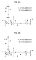
- FIGS. 4A and 4B are diagrams for illustrating the conceptual configuration of the present invention.
- FIG. 5 is a conceptual diagram illustrating the configuration of an SLO in a second embodiment of the present invention.
- an adaptive optics of the present invention that corrects the aberration of an examination object will be described with reference to the drawings.
- a configuration that corrects the aberration in the adaptive optics will be described with reference to FIG. 2 .
- the adaptive optics is applied to a fundus camera.
- the retina 81 is irradiated with first illumination light (not shown), and reflected or scattered light from a measurement point 811 on the retina 81 is imaged onto a light receiving sensor 4 through an ocular optical system 8 and optical systems 7 and 90.
- the light receiving sensor 4 is an imaging element in which light receiving units are arranged in a matrix.
- the aberrations include low-order aberrations, such as astigmatism, defocus, and tilt, that can be corrected by an optical element such as a cylindrical lens and high-order aberrations, such as coma aberration and fourth-order spherical aberration. These aberrations are caused by distortion of curved surface or nonuniformity in refractive index of the anterior segment, such as a cornea or a lens. These factors vary greatly from individual to individual and include factors that change with time, such as the state of the tear layer on the surface of the cornea. In the adaptive optics (AO), these aberrations are measured by a wavefront aberration detector and are corrected by a wavefront aberration corrector. In the configuration of the AO of FIG.
- the optical system has a wavefront aberration correction unit 10 disposed at a position optically conjugate to the entrance pupil (the pupil of the eye).
- a wavefront aberration detector (Shack-Hartmann sensor: HS sensor) 2 is disposed at another conjugate position on a branch formed by a branch member 52, such as an optical splitter.
- the wavefront aberration detector will hereinafter be referred to as HS sensor.
- a second light source 15 (a light source that emits light for aberration measurement) for detecting wavefront aberration is provided. Light from the light source 15 is incident on the eye 8 through a branch member 51 and is collected onto a measurement point 811 on the retina 81.
- a configuration such that light for aberration measurement is emitted from the vicinity of the eye can prevent stray light, for example, due to a lens of an optical system (intense reflected light near the center of a lens) from being detected by the wavefront sensor 2.
- the reflected or backscattered light 42 from this point 811 is converted into substantially parallel light by an ocular optical system such as the cornea, passes through the branch member 51, is converted by the optical system 7 into a light beam having a predetermined diameter, is then reflected by the branch member 52, and is incident on the HS sensor 2.
- FIG. 3 The principle of detection of the HS sensor 2 is illustrated in FIG. 3 .
- Light having a wavefront 85 such as that shown in FIG. 3 and incident on the HS sensor 2 is caused to form spots on a two-dimensional light receiving element 22 by subapertures of lens elements of a microlens array 21 disposed at a position optically conjugate to the pupil.
- These spots each form an image, according to the gradient of the wavefront incident on the sub-aperture, at a position at a distance of dy k from the optical axis position (shown by chain line) of each microlens on the two-dimensional light receiving element 22.
- Let f denote the focal length of each microlens.
- the wavefront in the wavefront aberration correction unit 10 has the same shape W (x', y').
- control is performed such that an aberration of -W (x', y') is given in the wavefront aberration correction unit 10. The above-described series of calculation and control is performed by a calculator 30.
- the reflected or backscattered light 42 from the point 811 passes through the anterior segment 82 of the eye and the optical system 7, then the wavefront of the light 42 is corrected by the wavefront aberration correction unit 10, and the light 42 is imaged by the imaging lens 90 onto the light receiving sensor 4.
- the wavefront aberration correction unit 10 is not driven, the light collection spot on the retina is a distorted and enlarged spot due to the aberration caused by the imperfection of the ocular optical system. Since the aberration is corrected by the wavefront aberration correction unit 10, light is collected to a spot according to a desired resolution.
- a DM is most commonly used as the wavefront aberration correction unit 10.
- a reflective LCOS (Liquid Crystal on Silicon) -SLM is used here.
- an SLM that uses orientational control of liquid crystal is disadvantageous in that it can modulate only a polarized light component in a particular direction (intrinsic polarization direction).
- reference numeral 1 denotes an SLM.
- the polarization of light once modulated in the SLM1 is rotated 90°, and the light is incident on the SLM1 again and is modulated.
- Polarizers are not disposed in front of and behind the SLM1 to limit the polarized light component.
- Incident light 41 is incident on and is reflected by the SLM1, and the reflected light is folded by a mirror 12 and is incident on the SLM1 again.
- a quarter wave plate 13 is disposed so that light passes through it twice, outward and return.
- the incident light 41 has both P- and S-polarized light components.
- the P-polarized light component (first polarized light component) shown in FIG. 4A will be discussed.
- the incident light 41 is P-polarized light having the same polarization direction as the modulation direction (intrinsic polarization direction) 11 of the SLM1. Therefore, when the light 41 is first incident on the SLM1, the light 41 is phase-modulated by a set amount of modulation and reflected by the SLM1.
- the reflected light 43 passes through the quarter wave plate 13 and becomes right-handed circularly polarized light, and it is reflected by the folding mirror 12 and becomes left-handed circularly polarized light.
- the light 43 passes through the quarter wave plate 13 again, becomes S-polarized light, and is incident on the SLM1 again.
- the polarization direction is perpendicular to the modulation direction 11 (intrinsic polarization direction, P-polarized light or S-polarized light can be modulated) of the SLM1, and therefore the light 43 is not modulated and is simply reflected.
- the incident light 41 is S-polarized light and differs by 90° from the modulation direction (intrinsic polarization direction) 11 of the SLM1. Therefore, when the light 41 is first incident on the SLM1, the light 41 is not modulated and is simply reflected.
- the reflected light 43 passes through the quarter wave plate 13 and becomes left-handed circularly polarized light, and it is reflected by the folding mirror 12 and becomes right-handed circularly polarized light.
- the light 43 passes through the quarter wave plate 13 again, becomes S-polarized light, and is incident on the SLM1 again.
- the polarization direction of the light 43 is the same as the modulation direction (intrinsic polarization direction) of the SLM1. This time, the light 43 is phase-modulated by a set amount of modulation and reflected by the SLM1. In FIGS. 4A and 4B , it looks as if the incident light and the reflected light traveled along different optical paths. However, this is for convenience of illustration. Actually, the incident light and the reflected light travel along the same optical path. Although the P-polarized light component and the S-polarized light component are separately shown, this is also for convenience of illustration. Actually, FIGS. 4A and 4B show events occurring in the same optical path at the same time. Due to this configuration, both polarized light components can be modulated with a single SLM1.
- each ray forming the light beam must be incident on the same incident point on the SLM1 as the incident point in its first incidence on the SLM1. If the incident point differ between the first and second incidence, the P-polarized light component and the S-polarized light component after the correction have different wavefronts because the same SLM1 performs the same modulation.
- a parallel light beam is incident on a wavefront aberration corrector. Therefore, when the amount of aberration to be corrected is small, the difference in incident point of each ray between the first and second incidence can be reduced by reducing the distance between the SLM1 and the folding mirror 12.
- the light beam is not parallel, and therefore a configuration such as that of FIGS. 4A and 4B cannot sufficiently correct aberration.
- the reason is that the P-polarized light component, which is modulated in the outward path, is properly corrected but the wavefront of the S-polarized light component that is incident on the SLM1 in the return path is changed to a wavefront different from the wavefront at the time when the P-polarized light component is incident on the SLM1. At this time, the S component is not properly corrected, and therefore the whole light beam is not sufficiently corrected.
- Each ray is incident on the same position on the SLM1 in both the outward path and the return path only when the SLM1 surface at the time of the first incidence and the SLM1 surface at the time of the second incidence are optically conjugate to each other, are of the same magnification, and are in an erected image relationship. When they are in a conjugate relationship but the second incident surface is an inverted image relative to the first incident surface or they differ in magnification, each ray is not incident on the same position on the SLM1 again, and each polarized light component is differently modulated.
- a configuration such that the SLM1 surface in the outward path and the SLM1 surface in the return path are optically conjugate is provided in the folding optical path of the SLM1.
- the present invention is not limited to this. It is also possible to modulate the P-polarized light component or the S-polarized light component of light, to rotate the light by 90 degrees, and then to cause the light to be incident on another SLM. In this case, two SLMs are provided.
- an optical image taking apparatus (an OCT in this embodiment) that examines a fundus to which the present invention is applied.
- the OCT of this embodiment is an SD-OCT (Spectral Domain OCT) including an observation system 101, a reference system 102, a light source 103, and a spectrometer 104.
- An SLD that emits light having a wavelength of 850 nm, which is poorly absorbed and poorly scattered by components of an eye, is used as the light source 103.
- Light emitted from the light source 103 propagates through a single-mode fiber 91 and is split by a coupler 201 into measurement light and reference light.
- the measurement light propagates through a fiber 99 to the observation system 101, and the reference light propagates through a fiber 98 to the reference system 102. After going out of the fiber 99 and being imaged onto the retina 81 of an eye 8 through an optical system of the observation system 101, the measurement light becomes backscattered or reflected light, goes back through the observation system 101, and re-enters the fiber 99.
- the reference light is sent to the reference system 102, is collimated by a collimator lens 920, passes through dispersion compensating glass 202, is reflected by a reference mirror 203, passes through the reference system 102 again, and returns to the fiber 98.
- the lights returned to the fibers 98 and 99 are coupled by the coupler 201.
- the resultant light propagates through a fiber 92 to the spectrometer 104, goes out of the fiber end, and is collimated by a collimator lens 940.
- the collimated light is diffracted by a holographic grating 401 and is imaged by an imaging lens 402 onto a line sensor 403.
- the light is separated according to wavelength by the grating 401, and therefore a spectral intensity distribution is obtained in the line sensor 403.
- a spectral intensity distribution is obtained in the line sensor 403.
- interference fringes are produced in this spectral intensity distribution.
- wavefront aberration measurement light from the illumination light source 15 is reflected by the branch member 51, is incident on the eye 8, and is collected onto the measurement point on the retina 81.
- the wavelength of the light source 15 is 780 nm.
- the branch member 52 reflects part of light having this wavelength.
- the reflected or backscattered light (return light) from this point is influenced by the aberration of the ocular optical system, and the wavefront thereof is distorted.
- the light goes back the same optical path, passes through the pupil 82 to the optical system 71, is reflected by the branch member 52, and is incident on the HS sensor 2.
- the branch member 52 reflects 780 nm light and transmits 850 nm light.
- incident light is imaged by each subaperture onto the imaging element. From the displacement of the spots, wavefront aberration is calculated by the calculator 30.
- the SLM 1 is driven.
- 850 nm illumination light (measurement light) for fundus examination going out of the fiber end 99 is collimated by the collimator lens 9, passes through the branch member 52, is enlarged or reduced and collimated by the optical system 71, and is incident on and reflected by the SLM 1.
- the light is phase-modulated by the SLM1 and the wavefront thereof is changed.
- the light passes through the optical system 72, is reflected by the SLM1 again, passes through the optical system 73, the scanner mirror 6, and the optical system 7, and is incident on the eye 8.
- the pupil of the collimator lens, the SLM1, the scanner mirror 6, the pupil 81 of the eye are optically conjugate.
- This measurement light has a wavefront that compensates for the aberration of the ocular optical system when incident on the pupil 82.
- the light is in a good (low-aberration) state when collected onto the retina 81.
- the reflected or backscattered light from the irradiation point on the retina 81 is influenced by the aberration of the ocular optical system, and the wavefront thereof is distorted.
- the light goes back the same optical path, passes through the pupil 82 to the optical system 73, and is incident on the SLM1.
- the distorted wavefront is incident on the SLM1 twice, is corrected on the basis of the wavefront aberration calculated by the HS sensor 2, and is brought into a low-aberration state.
- the light passes through the optical system 71, the branch member 52, and the collimator lens 9, and is incident on the fiber 99. This feedback is repeated, the wavefront aberration converges toward a low state, and the reflected or backscattered light from the retina is well coupled into the fiber 99. Therefore, the tomographic image obtained by interference is high S/N, bright, and high-contrast.
- the optical system 72 includes two curved mirrors having the same focal length and is set such that the SLM surface in the outward path and the SLM surface in the return path are optically conjugate and of the same magnification.
- a ray reflected at a point 11 on the SLM1 passes through the optical system 72 along the arrow and is then incident on this point 11 again. Therefore, in the above-described process, the P- and S-polarized light components are modulated once by the same amount.
- conditions for each ray to be incident on the same position on the SLM1 in both the outward path and the return path are satisfied.
- the folding optical system is not a double-path optical system, and the incident angle on the SLM1 differs between the outward path and the return path. Therefore, the incident light from the fiber end 99 and the outgoing light heading to the eye differ in direction, and the loss due to use of a branch member can be avoided.
- an optical image taking apparatus an SLO in this embodiment
- the same reference numerals are used to designate basically the same components as those in FIG. 1 .
- a light source that emits light for aberration measurement is separately provided.
- illumination light for fundus examination is also used as wavefront aberration measurement light.
- SLO of this embodiment denoted by reference numeral 110 in FIG.
- illumination (measurement) light from a light source is coupled into a single-mode fiber 99, propagates therethrough, becomes diverging light after going out of the exit end, is collimated by a collimator lens 9, and passes through a branch member 52.
- the core diameter of the fiber is 5 ⁇ m
- the focal length of the collimator lens is about 10 mm
- the diameter of the collimated light is about 4 mm.
- the light is converted into parallel light of about 8 mm by an optical system 71 and is incident on an SLM 1.
- the SLM1 is not modulated, and the wavefront of the parallel light is not changed.
- the parallel light passes through an optical system 72, is incident on and reflected by the SLM1 again, passes through an optical system 73, a scanner mirror 6, and an optical system 7, and is incident on an eye 8.
- the pupil of the collimator lens, the SLM1, the scanner mirror 6, the pupil 82 of the eye, and a flat mirror 12 for folding are optically conjugate.
- the diameter of light incident on the scanner mirror 6 is set to 6 mm, and the diameter of light incident on the eye 8 is also set to 6 mm.
- the surface normal of the mirror 12 is inclined at 4° to the principal ray of the incident light.
- the reflected light is at an angle different from that of the incident light.
- the reflected light passes through the optical system 73 again, and is incident on the SLM1 again.
- the mirror 12 and the SLM1 are optically conjugate and of the same magnification. Therefore, the incident light on the SLM1 in the outward path and the incident light on the SLM1 in the return path differ in angle and are incident on the same position.
- the measurement light incident on the eye 8 is collected onto the retina 81.
- the reflected or backscattered light from this point is influenced by the aberration of the ocular optical system, and the wavefront thereof is disordered.
- the light goes back the same optical path and passes through the pupil 82 to the optical system 71.
- Part of the light is reflected by the branch member 52 and is incident on the HS sensor 2.
- wavefront aberration is calculated by a calculator 30.
- the SLM 1 is driven.
- the measurement light to the eye has a wavefront that compensates for the aberration of the ocular optical system when incident on the pupil 82.
- the light is in a good (low-aberration) state when collected onto the retina 81.
- the reflected or backscattered light (return light) from the irradiation point on the retina is influenced by the aberration of the ocular optical system again, and the wavefront thereof is disordered.
- the light goes back the same optical path, passes through the pupil 82 to the optical system 73, and is incident on the SLM 1.
- the distorted wavefront is corrected by the SLM 1 and is brought into a low-aberration state.
- the light passes through the branch member 52 and the collimator lens 9 and is incident on the fiber 99. After propagating through the fiber 99, the light is split by a branch member (not shown) beyond the fiber 99 and is incident on a photoelectric sensor such as an avalanche photodiode, where the quantity of light is measured.
- the two-dimensional retina image obtained is high S/N, bright, and high-contrast.
- the incident angle on the SLM1 differs between the outward path and the return path. Therefore, the incident light (measurement light) from the fiber end 99 and the outgoing light (return light) heading to the eye differ in direction, and the loss due to use of a branch member can be avoided. In addition, because the outward path and the return path share a common optical system, the space can be saved. In the above-described SLO 110, low-order aberrations such as astigmatism and defocus may be corrected by the SLM1.
- a deformable mirror may be used as the folding mirror 12.
- a deformable mirror that has a small number of actuators and cannot reproduce a high-order curved surface but is capable of a large amount of correction on a low-order curved surface, low-order aberrations are corrected, and third- or higher-order aberrations are corrected by the SLM1.
- the amplitude of high-order aberrations is generally small. Therefore, the amount of modulation of the LCOS1 can be reduced, and problems caused by a large amount of modulation can be prevented.
- aspects of the present invention can also be realized by a computer of a system or apparatus (or devices such as a CPU or MPU) that reads out and executes a program recorded on a memory device to perform the functions of the above-described embodiment(s), and by a method, the steps of which are performed by a computer of a system or apparatus by, for example, reading out and executing a program recorded on a memory device to perform the functions of the above-described embodiment(s).
- the program is provided to the computer for example via a network or from a recording medium of various types serving as the memory device (e.g., computer-readable medium) .
Landscapes
- Physics & Mathematics (AREA)
- Health & Medical Sciences (AREA)
- Life Sciences & Earth Sciences (AREA)
- General Physics & Mathematics (AREA)
- Optics & Photonics (AREA)
- Biomedical Technology (AREA)
- Ophthalmology & Optometry (AREA)
- Engineering & Computer Science (AREA)
- Biophysics (AREA)
- Heart & Thoracic Surgery (AREA)
- Medical Informatics (AREA)
- Molecular Biology (AREA)
- Surgery (AREA)
- Animal Behavior & Ethology (AREA)
- General Health & Medical Sciences (AREA)
- Public Health (AREA)
- Veterinary Medicine (AREA)
- Eye Examination Apparatus (AREA)
Abstract
Description
- The present invention relates to an adaptive optics apparatus that corrects aberration of an examination object, and an image taking apparatus including an adaptive optics apparatus, and more specifically, it relates to a technique suitable for an optical image taking apparatus used, for example, for ophthalmic care and including an adaptive optics that corrects aberration of an eye.
- In an apparatus that is used, for example, for astronomical observation or fundus examination and measures an object using light, factors that lie between a measurement object and a detection optical system and fluctuate with time or vary greatly from individual to individual affect the imaging performance of the optical system and in some cases make it impossible to obtain sufficient resolution. These factors are caused, for example, by atmospheric fluctuation, change in a tear film of an eye, or individual difference in imperfection of an ocular optical system, include high-order optical aberration components, and are often not sufficiently corrected by an optical system including lenses and mirrors. A technique of an adaptive optics (hereinafter referred to as AO) is known that measures the changing aberration and feedback-controls the aberration using a device capable of dealing with high-order aberration.
- In the case of fundus examination (in this case, the examination object is an eye), it is desirable to identify a photoreceptor cell unit on a retina, the size of which is of the order of magnitude of 2 to 3 µm. Ultimately, it is desirable to achieve an optical biopsy capable of cellular imaging in the near future. In order to achieve this, a spatial resolution of 1 µm or less comparable to a microscopical image of a piece of tissue is required. The wavelength of light used for such retina examination must be within the near infrared or infrared region in which light is poorly absorbed by water, which is the major component of the body tissue, and is poorly scattered in the tissue. In order to obtain a lateral resolution of 1 to 3 µm, the diameter of a beam incident on the pupil needs to be about 6 to 8 mm. Actually, in an optical system of an eye, from a cornea to a vitreous body, the state of the curved surface and the refractive index of each tissue are often not uniform. Even when an eye is observed with a beam having a diameter of about 6 to 8 mm, the wavefront of light is distorted in the eye, and a desired resolution cannot be obtained.
- In Opt. Express 13, 8532 (2005) is reported a method to obtain desired light-collecting performance by using the AO technique, detecting aberration of a wavefront distorted in an eye, and compensating for the aberration with an aberration corrector. The AO in Opt. Express 13, 8532 (2005) employs a deformable mirror (hereinafter referred to as DM) including a wavefront aberration detector and 35 actuators. It is reported that an optical coherence tomography (hereinafter referred to as OCT) having such an adaptive optics achieved a resolution in the lateral direction of 4 µm and a resolution in the depth direction of 6 µm. In the case of such a DM, the optimal mirror shape to correct the aberration is formed by pushing and pulling a continuous surface mirror with several tens of actuators. Therefore, interaction between actuators occurs and complicates control calculation. Depending on the aberration shape, a desired shape cannot be sufficiently reproduced.
- Japanese Patent Laid-Open No.
2007-014569 2007-014569 - However, an AO that employs an SLM that uses orientational control of liquid crystal, such as that in Japanese Patent Laid-Open No.
2007-014569 2007-014569 - When such light is incident on the SLM, a polarized light component perpendicular to the modulation direction cannot be modulated, and outgoing light from the SLM includes two polarized light components that differ in spatial phase state (differ in wavefront). The component that is not the intrinsic polarized light of the SLM is not efficiently modulated, the wavefront cannot be sufficiently corrected, and therefore a desired resolution cannot be obtained. Disposing a polarizer that is parallel to the modulated polarization direction in front of the SLM makes it possible to select modulated light component. However, the polarized light component that is not modulated is removed, and therefore light use efficiency is significantly lowered. A retina has a low reflectivity, and the power of light illuminating it is limited by standards for safety. In the case of an examination object like a retina, it may be difficult to obtain a good-quality image when light quantity loss is about half.
- The present invention in its first aspect provides an adaptive optics apparatus as specified in claims 1 to 7.
- The present invention in its second aspect provides an image taking apparatus as specified in
claims - The present invention in its third aspect provides an adaptive optics method as specified in
claim 10. - The present invention can provide an adaptive optics apparatus capable of reducing the influence of the polarization state of incident light on the modulation characteristic, improving light use efficiency, and correcting aberration of an examination object even when a modulating unit (light modulating unit) that functions in a single polarization direction is employed, and an image taking apparatus including an adaptive optics apparatus.
- Further features of the present invention will become apparent from the following description of exemplary embodiments with reference to the attached drawings.
-
FIG. 1 is a conceptual diagram illustrating the configuration of an OCT in a first embodiment of the present invention. -
FIG. 2 is a conceptual diagram illustrating aberration correction with a fundus examination device including an adaptive optics including a wavefront aberration correction unit. -
FIG. 3 is a principle diagram illustrating a wavefront aberration detector. -
FIGS. 4A and 4B are diagrams for illustrating the conceptual configuration of the present invention. -
FIG. 5 is a conceptual diagram illustrating the configuration of an SLO in a second embodiment of the present invention. - Next, an adaptive optics of the present invention that corrects the aberration of an examination object will be described with reference to the drawings. First, a configuration that corrects the aberration in the adaptive optics will be described with reference to
FIG. 2 . It is assumed that the adaptive optics is applied to a fundus camera. To obtain the information on aretina 81 of an eye 8 (examination object) noninvasively and optically, theretina 81 is irradiated with first illumination light (not shown), and reflected or scattered light from ameasurement point 811 on theretina 81 is imaged onto a light receiving sensor 4 through an ocularoptical system 8 andoptical systems light 42 going out of the eye has aberration. When this light is imaged onto the light receiving sensor 4 by theoptical systems - The aberrations include low-order aberrations, such as astigmatism, defocus, and tilt, that can be corrected by an optical element such as a cylindrical lens and high-order aberrations, such as coma aberration and fourth-order spherical aberration. These aberrations are caused by distortion of curved surface or nonuniformity in refractive index of the anterior segment, such as a cornea or a lens. These factors vary greatly from individual to individual and include factors that change with time, such as the state of the tear layer on the surface of the cornea. In the adaptive optics (AO), these aberrations are measured by a wavefront aberration detector and are corrected by a wavefront aberration corrector. In the configuration of the AO of
FIG. 2 , the optical system has a wavefrontaberration correction unit 10 disposed at a position optically conjugate to the entrance pupil (the pupil of the eye). A wavefront aberration detector (Shack-Hartmann sensor: HS sensor) 2 is disposed at another conjugate position on a branch formed by abranch member 52, such as an optical splitter. The wavefront aberration detector will hereinafter be referred to as HS sensor. A second light source 15 (a light source that emits light for aberration measurement) for detecting wavefront aberration is provided. Light from thelight source 15 is incident on theeye 8 through abranch member 51 and is collected onto ameasurement point 811 on theretina 81. A configuration such that light for aberration measurement is emitted from the vicinity of the eye can prevent stray light, for example, due to a lens of an optical system (intense reflected light near the center of a lens) from being detected by thewavefront sensor 2. When the diopter is zero, the reflected or backscattered light 42 from thispoint 811 is converted into substantially parallel light by an ocular optical system such as the cornea, passes through thebranch member 51, is converted by theoptical system 7 into a light beam having a predetermined diameter, is then reflected by thebranch member 52, and is incident on theHS sensor 2. - The principle of detection of the
HS sensor 2 is illustrated inFIG. 3 . Light having awavefront 85 such as that shown inFIG. 3 and incident on theHS sensor 2 is caused to form spots on a two-dimensionallight receiving element 22 by subapertures of lens elements of amicrolens array 21 disposed at a position optically conjugate to the pupil. These spots each form an image, according to the gradient of the wavefront incident on the sub-aperture, at a position at a distance of dyk from the optical axis position (shown by chain line) of each microlens on the two-dimensionallight receiving element 22. Let f denote the focal length of each microlens. The gradient yk of the wavefront is calculated by yk = dyk / f. By putting together the wavefront gradient calculated in each subaperture, the curved surface of thewavefront 85 is obtained in the form of W (x, y). TheHS sensor 2 is optically conjugate to the wavefrontaberration correction unit 10. Therefore, the wavefront in the wavefrontaberration correction unit 10 has the same shape W (x', y'). In order to correct the wavefront of the reflected light from the wavefrontaberration correction unit 10 and to make it a substantially plane wave, control is performed such that an aberration of -W (x', y') is given in the wavefrontaberration correction unit 10. The above-described series of calculation and control is performed by acalculator 30. - The reflected or backscattered light 42 from the
point 811 passes through theanterior segment 82 of the eye and theoptical system 7, then the wavefront of the light 42 is corrected by the wavefrontaberration correction unit 10, and the light 42 is imaged by theimaging lens 90 onto the light receiving sensor 4. If the wavefrontaberration correction unit 10 is not driven, the light collection spot on the retina is a distorted and enlarged spot due to the aberration caused by the imperfection of the ocular optical system. Since the aberration is corrected by the wavefrontaberration correction unit 10, light is collected to a spot according to a desired resolution. A DM is most commonly used as the wavefrontaberration correction unit 10. However, in view of characteristic superiority, a reflective LCOS (Liquid Crystal on Silicon) -SLM is used here. However, as described above, an SLM that uses orientational control of liquid crystal is disadvantageous in that it can modulate only a polarized light component in a particular direction (intrinsic polarization direction). - Next, the conceptual configuration of the present invention, which solves such a problem, will be described with reference to
FIGS. 4A and 4B . InFIGS. 4A and 4B , reference numeral 1 denotes an SLM. In the present invention, as shown inFIG. 4A and 4B , the polarization of light once modulated in the SLM1 is rotated 90°, and the light is incident on the SLM1 again and is modulated. Polarizers are not disposed in front of and behind the SLM1 to limit the polarized light component.Incident light 41 is incident on and is reflected by the SLM1, and the reflected light is folded by amirror 12 and is incident on the SLM1 again. Between the SLM1 and thefolding mirror 12, aquarter wave plate 13 is disposed so that light passes through it twice, outward and return. - The
incident light 41 has both P- and S-polarized light components. First, the P-polarized light component (first polarized light component) shown inFIG. 4A will be discussed. Theincident light 41 is P-polarized light having the same polarization direction as the modulation direction (intrinsic polarization direction) 11 of the SLM1. Therefore, when the light 41 is first incident on the SLM1, the light 41 is phase-modulated by a set amount of modulation and reflected by the SLM1. The reflected light 43 passes through thequarter wave plate 13 and becomes right-handed circularly polarized light, and it is reflected by thefolding mirror 12 and becomes left-handed circularly polarized light. The light 43 passes through thequarter wave plate 13 again, becomes S-polarized light, and is incident on the SLM1 again. At this time, the polarization direction is perpendicular to the modulation direction 11 (intrinsic polarization direction, P-polarized light or S-polarized light can be modulated) of the SLM1, and therefore the light 43 is not modulated and is simply reflected. - Next, the S-polarized light component (second polarized light component) shown in
FIG. 4B will be discussed. Theincident light 41 is S-polarized light and differs by 90° from the modulation direction (intrinsic polarization direction) 11 of the SLM1. Therefore, when the light 41 is first incident on the SLM1, the light 41 is not modulated and is simply reflected. The reflected light 43 passes through thequarter wave plate 13 and becomes left-handed circularly polarized light, and it is reflected by thefolding mirror 12 and becomes right-handed circularly polarized light. The light 43 passes through thequarter wave plate 13 again, becomes S-polarized light, and is incident on the SLM1 again. The polarization direction of the light 43 is the same as the modulation direction (intrinsic polarization direction) of the SLM1. This time, the light 43 is phase-modulated by a set amount of modulation and reflected by the SLM1. InFIGS. 4A and 4B , it looks as if the incident light and the reflected light traveled along different optical paths. However, this is for convenience of illustration. Actually, the incident light and the reflected light travel along the same optical path. Although the P-polarized light component and the S-polarized light component are separately shown, this is also for convenience of illustration. Actually,FIGS. 4A and 4B show events occurring in the same optical path at the same time. Due to this configuration, both polarized light components can be modulated with a single SLM1. Therefore, ignoring reflectivity, diffraction efficiency, and the like, loss of light quantity power used does not occur. By employing the unit ofFIGS. 4A and 4B as the wavefrontaberration correction unit 10 ofFIG. 2 , a bright and high S/N ratio image can be obtained even if wavefront aberration is corrected using a polarization-dependent SLM. - When a light beam is incident on the SLM1 again (reflected by the SLM1), each ray forming the light beam must be incident on the same incident point on the SLM1 as the incident point in its first incidence on the SLM1. If the incident point differ between the first and second incidence, the P-polarized light component and the S-polarized light component after the correction have different wavefronts because the same SLM1 performs the same modulation. Usually, a parallel light beam is incident on a wavefront aberration corrector. Therefore, when the amount of aberration to be corrected is small, the difference in incident point of each ray between the first and second incidence can be reduced by reducing the distance between the SLM1 and the
folding mirror 12. However, when the amount of aberration to be corrected is large, the light beam is not parallel, and therefore a configuration such as that ofFIGS. 4A and 4B cannot sufficiently correct aberration. The reason is that the P-polarized light component, which is modulated in the outward path, is properly corrected but the wavefront of the S-polarized light component that is incident on the SLM1 in the return path is changed to a wavefront different from the wavefront at the time when the P-polarized light component is incident on the SLM1. At this time, the S component is not properly corrected, and therefore the whole light beam is not sufficiently corrected. - Each ray is incident on the same position on the SLM1 in both the outward path and the return path only when the SLM1 surface at the time of the first incidence and the SLM1 surface at the time of the second incidence are optically conjugate to each other, are of the same magnification, and are in an erected image relationship. When they are in a conjugate relationship but the second incident surface is an inverted image relative to the first incident surface or they differ in magnification, each ray is not incident on the same position on the SLM1 again, and each polarized light component is differently modulated.
In the present invention, in order to satisfy such conditions, a configuration such that the SLM1 surface in the outward path and the SLM1 surface in the return path are optically conjugate is provided in the folding optical path of the SLM1. - Although a case where light is incident on the SLM again has been described above, the present invention is not limited to this. It is also possible to modulate the P-polarized light component or the S-polarized light component of light, to rotate the light by 90 degrees, and then to cause the light to be incident on another SLM. In this case, two SLMs are provided.
- Next, embodiments of the present invention will be described.
- In a first embodiment, with reference to
FIG. 1 , a description will be given of an optical image taking apparatus (an OCT in this embodiment) that examines a fundus to which the present invention is applied. The OCT of this embodiment is an SD-OCT (Spectral Domain OCT) including anobservation system 101, areference system 102, alight source 103, and aspectrometer 104. An SLD that emits light having a wavelength of 850 nm, which is poorly absorbed and poorly scattered by components of an eye, is used as thelight source 103. Light emitted from thelight source 103 propagates through a single-mode fiber 91 and is split by acoupler 201 into measurement light and reference light. The measurement light propagates through afiber 99 to theobservation system 101, and the reference light propagates through afiber 98 to thereference system 102. After going out of thefiber 99 and being imaged onto theretina 81 of aneye 8 through an optical system of theobservation system 101, the measurement light becomes backscattered or reflected light, goes back through theobservation system 101, and re-enters thefiber 99. - On the other hand, after propagating through the
fiber 98, the reference light is sent to thereference system 102, is collimated by acollimator lens 920, passes throughdispersion compensating glass 202, is reflected by areference mirror 203, passes through thereference system 102 again, and returns to thefiber 98. The lights returned to thefibers coupler 201. The resultant light propagates through afiber 92 to thespectrometer 104, goes out of the fiber end, and is collimated by acollimator lens 940. The collimated light is diffracted by aholographic grating 401 and is imaged by animaging lens 402 onto aline sensor 403. The light is separated according to wavelength by thegrating 401, and therefore a spectral intensity distribution is obtained in theline sensor 403. When the optical path length of the observation optical path from the branch point to the fundus is substantially equal to that of the reference optical path, interference fringes are produced in this spectral intensity distribution. By making this signal an intensity distribution relative to the wavenumber and then performing a Fourier transform thereon, an intensity distribution relative to the depth direction of the retina called "A scan data" is obtained. If light is scanned on theretina 81 by ascanner 6 and this intensity distribution is obtained in synchronization, a tomographic image of theretina 81 called "B scan image" is obtained. - The configuration in the
observation system 101 will be described in more detail. First, wavefront aberration measurement light from theillumination light source 15 is reflected by thebranch member 51, is incident on theeye 8, and is collected onto the measurement point on theretina 81. The wavelength of thelight source 15 is 780 nm. Thebranch member 52 reflects part of light having this wavelength. The reflected or backscattered light (return light) from this point is influenced by the aberration of the ocular optical system, and the wavefront thereof is distorted. The light goes back the same optical path, passes through thepupil 82 to theoptical system 71, is reflected by thebranch member 52, and is incident on theHS sensor 2. Thebranch member 52 reflects 780 nm light and transmits 850 nm light. In theHS sensor 2, incident light is imaged by each subaperture onto the imaging element. From the displacement of the spots, wavefront aberration is calculated by thecalculator 30. - On the other hand, 850 nm illumination light (measurement light) for fundus examination going out of the
fiber end 99 is collimated by thecollimator lens 9, passes through thebranch member 52, is enlarged or reduced and collimated by theoptical system 71, and is incident on and reflected by the SLM 1. The light is phase-modulated by the SLM1 and the wavefront thereof is changed. The light passes through theoptical system 72, is reflected by the SLM1 again, passes through theoptical system 73, thescanner mirror 6, and theoptical system 7, and is incident on theeye 8. The pupil of the collimator lens, the SLM1, thescanner mirror 6, thepupil 81 of the eye are optically conjugate. This measurement light has a wavefront that compensates for the aberration of the ocular optical system when incident on thepupil 82. As a result, the light is in a good (low-aberration) state when collected onto theretina 81. The reflected or backscattered light from the irradiation point on theretina 81 is influenced by the aberration of the ocular optical system, and the wavefront thereof is distorted. The light goes back the same optical path, passes through thepupil 82 to theoptical system 73, and is incident on the SLM1. The distorted wavefront is incident on the SLM1 twice, is corrected on the basis of the wavefront aberration calculated by theHS sensor 2, and is brought into a low-aberration state. The light passes through theoptical system 71, thebranch member 52, and thecollimator lens 9, and is incident on thefiber 99. This feedback is repeated, the wavefront aberration converges toward a low state, and the reflected or backscattered light from the retina is well coupled into thefiber 99. Therefore, the tomographic image obtained by interference is high S/N, bright, and high-contrast. - The process of modulation in the SLM1 will be described in more detail. When the measurement light from the
optical system 71 is first incident on the SLM1, only the P-polarized light component thereof is modulated. The light passes through the foldingoptical system 72 and is incident on the SLM1 again. In the folding optical path is disposed ahalf wave plate 13, where each polarized light component is rotated 90°. Therefore, when this light is incident on the SLM1 again, only a component that is S-polarized light in the outward path and is converted into P-polarized light by the wave plate in the return path is modulated. Theoptical system 72 includes two curved mirrors having the same focal length and is set such that the SLM surface in the outward path and the SLM surface in the return path are optically conjugate and of the same magnification. In order to form an erected image, a ray reflected at apoint 11 on the SLM1 passes through theoptical system 72 along the arrow and is then incident on thispoint 11 again. Therefore, in the above-described process, the P- and S-polarized light components are modulated once by the same amount. In this embodiment, due to such a configuration, conditions for each ray to be incident on the same position on the SLM1 in both the outward path and the return path are satisfied. In this optical system, the folding optical system is not a double-path optical system, and the incident angle on the SLM1 differs between the outward path and the return path. Therefore, the incident light from thefiber end 99 and the outgoing light heading to the eye differ in direction, and the loss due to use of a branch member can be avoided. - In a second embodiment, with reference to
FIG. 5 , a description will be given of an optical image taking apparatus (an SLO in this embodiment) to which the present invention is applied. InFIG. 5 , the same reference numerals are used to designate basically the same components as those inFIG. 1 . In the first embodiment, a light source that emits light for aberration measurement is separately provided. In this embodiment, illumination light (measurement light) for fundus examination is also used as wavefront aberration measurement light. In the SLO of this embodiment denoted byreference numeral 110 inFIG. 5 , illumination (measurement) light from a light source (not shown) is coupled into a single-mode fiber 99, propagates therethrough, becomes diverging light after going out of the exit end, is collimated by acollimator lens 9, and passes through abranch member 52. The core diameter of the fiber is 5 µm, the focal length of the collimator lens is about 10 mm, and the diameter of the collimated light is about 4 mm. After that, the light is converted into parallel light of about 8 mm by anoptical system 71 and is incident on an SLM 1. At this time, the SLM1 is not modulated, and the wavefront of the parallel light is not changed. The parallel light passes through anoptical system 72, is incident on and reflected by the SLM1 again, passes through anoptical system 73, ascanner mirror 6, and anoptical system 7, and is incident on aneye 8. The pupil of the collimator lens, the SLM1, thescanner mirror 6, thepupil 82 of the eye, and aflat mirror 12 for folding are optically conjugate. The diameter of light incident on thescanner mirror 6 is set to 6 mm, and the diameter of light incident on theeye 8 is also set to 6 mm. The surface normal of themirror 12 is inclined at 4° to the principal ray of the incident light. The reflected light is at an angle different from that of the incident light. The reflected light passes through theoptical system 73 again, and is incident on the SLM1 again. At this time, themirror 12 and the SLM1 are optically conjugate and of the same magnification. Therefore, the incident light on the SLM1 in the outward path and the incident light on the SLM1 in the return path differ in angle and are incident on the same position. - The measurement light incident on the
eye 8 is collected onto theretina 81. The reflected or backscattered light from this point is influenced by the aberration of the ocular optical system, and the wavefront thereof is disordered. The light goes back the same optical path and passes through thepupil 82 to theoptical system 71. Part of the light is reflected by thebranch member 52 and is incident on theHS sensor 2. From the displacement of spots imaged by each subaperture onto the imaging element, wavefront aberration is calculated by acalculator 30. On the basis of it, the SLM 1 is driven.
By repeating this feedback, the measurement light to the eye has a wavefront that compensates for the aberration of the ocular optical system when incident on thepupil 82.
As a result, the light is in a good (low-aberration) state when collected onto theretina 81. - The reflected or backscattered light (return light) from the irradiation point on the retina is influenced by the aberration of the ocular optical system again, and the wavefront thereof is disordered. The light goes back the same optical path, passes through the
pupil 82 to theoptical system 73, and is incident on the SLM 1. The distorted wavefront is corrected by the SLM 1 and is brought into a low-aberration state. The light passes through thebranch member 52 and thecollimator lens 9 and is incident on thefiber 99. After propagating through thefiber 99, the light is split by a branch member (not shown) beyond thefiber 99 and is incident on a photoelectric sensor such as an avalanche photodiode, where the quantity of light is measured. By synchronizing this with a scanner mirror that performs two-dimensional scan, a two-dimensional image of the retina is formed. At this time, the reflected or backscattered light from the retina is well coupled into thefiber 99. Therefore, the two-dimensional retina image obtained is high S/N, bright, and high-contrast. - The process of modulation in the SLM1 will be described in more detail. When the light from the
optical system 71 is first incident on the SLM1, only the P-polarized light component thereof is modulated. The light passes through the foldingoptical system 72 and is incident on the SLM1 again. Aquarter wave plate 13 is disposed in the folding optical path. Passing through thequarter wave plate 13 twice (outward and return), each polarized light component is rotated by 90°. Therefore, when this light is incident on the SLM1 again, only a component that is S-polarized light component in the outward path and is converted into P-polarized light by the wave plate in the return path is modulated. In the above-described process, the P- and S-polarized light components are modulated once by the same amount. - Also in this folding
optical system 72, the incident angle on the SLM1 differs between the outward path and the return path. Therefore, the incident light (measurement light) from thefiber end 99 and the outgoing light (return light) heading to the eye differ in direction, and the loss due to use of a branch member can be avoided. In addition, because the outward path and the return path share a common optical system, the space can be saved. In the above-describedSLO 110, low-order aberrations such as astigmatism and defocus may be corrected by the SLM1. However, when the amount of correction is larger than 5D or when the wavelength interval of a light source used is about 100 nm, the decrease in diffraction efficiency and chromatic aberration are significant, and in some cases, desired correction performance cannot be obtained. In this case, instead of a flat mirror, a deformable mirror may be used as thefolding mirror 12. By using a deformable mirror that has a small number of actuators and cannot reproduce a high-order curved surface but is capable of a large amount of correction on a low-order curved surface, low-order aberrations are corrected, and third- or higher-order aberrations are corrected by the SLM1. The amplitude of high-order aberrations is generally small. Therefore, the amount of modulation of the LCOS1 can be reduced, and problems caused by a large amount of modulation can be prevented. - Aspects of the present invention can also be realized by a computer of a system or apparatus (or devices such as a CPU or MPU) that reads out and executes a program recorded on a memory device to perform the functions of the above-described embodiment(s), and by a method, the steps of which are performed by a computer of a system or apparatus by, for example, reading out and executing a program recorded on a memory device to perform the functions of the above-described embodiment(s). For this purpose, the program is provided to the computer for example via a network or from a recording medium of various types serving as the memory device (e.g., computer-readable medium) .
- While the present invention has been described with reference to exemplary embodiments, it is to be understood that the invention is not limited to the disclosed exemplary embodiments. The scope of the following claims is to be accorded the broadest interpretation so as to encompass all such modifications and equivalent structures and functions.
Claims (10)
- An adaptive optics apparatus comprising:first light modulating means arranged to perform modulation in a polarization direction of one of two polarized light components in light emitted from a light source;changing means arranged to rotate the light modulated by the first light modulating means by 90 degrees;second light modulating means arranged to modulate the light changed by the changing means in the polarization direction; andirradiating means arranged to irradiate a measurement object with the light modulated by the second light modulating means.
- The adaptive optics apparatus according to Claim 1, further comprising aberration measuring means arranged to measure aberration of the measurement object, wherein the first and second light modulating means are disposed at a position optically conjugate to the aberration measuring means.
- The adaptive optics apparatus according to Claim 2, wherein the measurement object is an eye under examination, the aberration occurs in an anterior segment of the eye under examination, and the first and second light modulating means are disposed at a position optically conjugate to the anterior segment.
- The adaptive optics apparatus according to Claim 2 or 3, wherein light used when the aberration measuring means measures the aberration and light used when an image of the measurement object is obtained are emitted from different light sources.
- The adaptive optics apparatus according to any one of Claims 1 to 4, further comprising means arranged to reflect the light rotated by 90 degrees by the changing means and to irradiate the second light modulating means therewith.
- The adaptive optics apparatus according to Claim 5, wherein the first light modulating means and the second light modulating means are the same.
- The adaptive optics apparatus according to any one of Claims 1 to 6, wherein the second light modulating means modulates return light from the measurement object irradiated by the irradiating means in a polarization direction of one of two polarized light components in the light, the changing means rotates the light modulated by the second light modulating means by 90 degrees, and the first light modulating means modulates the light changed by the changing means in the polarization direction.
- An image taking apparatus comprising:the adaptive optics apparatus according to any one of Claims 1 to 7; andimage obtaining means arranged to obtain an image of the measurement object on the basis of return light from the measurement object irradiated by the irradiating means.
- The image taking apparatus according to Claim 8, further comprising separating means arranged to separate the light from the light source into light to be incident on the first light modulating means and reference light, wherein the image obtaining means obtains a tomographic image of the measurement object on the basis of interfering light of the return light from the measurement object irradiated by the irradiating means and the reference light.
- An adaptive optics method comprising:a first light modulating step of performing modulation in a polarization direction of one of two polarized light components in light emitted from a light source;a changing step of rotating the light modulated in the first light modulating step by 90 degrees;a second light modulating step of modulating the light changed in the changing step in the polarization direction; andan irradiating step of irradiating a measurement object with the light modulated in the second light modulating step.
Applications Claiming Priority (1)
| Application Number | Priority Date | Filing Date | Title |
|---|---|---|---|
| JP2009244961A JP5350178B2 (en) | 2009-10-23 | 2009-10-23 | Compensating optical device, imaging device including compensating optical device, and compensating optical method |
Publications (2)
| Publication Number | Publication Date |
|---|---|
| EP2314204A1 true EP2314204A1 (en) | 2011-04-27 |
| EP2314204B1 EP2314204B1 (en) | 2015-04-01 |
Family
ID=43432249
Family Applications (1)
| Application Number | Title | Priority Date | Filing Date |
|---|---|---|---|
| EP10188407.0A Not-in-force EP2314204B1 (en) | 2009-10-23 | 2010-10-21 | Adaptive optics apparatus that corrects aberration of examination object and image taking apparatus including adaptive optics apparatus |
Country Status (4)
| Country | Link |
|---|---|
| US (2) | US8419187B2 (en) |
| EP (1) | EP2314204B1 (en) |
| JP (1) | JP5350178B2 (en) |
| CN (2) | CN102038487B (en) |
Families Citing this family (38)
| Publication number | Priority date | Publication date | Assignee | Title |
|---|---|---|---|---|
| US7758190B2 (en) | 2007-06-20 | 2010-07-20 | Tearscience, Inc. | Tear film measurement |
| US8192026B2 (en) | 2007-06-20 | 2012-06-05 | Tearscience, Inc. | Tear film measurement |
| US9888839B2 (en) | 2009-04-01 | 2018-02-13 | Tearscience, Inc. | Methods and apparatuses for determining contact lens intolerance in contact lens wearer patients based on dry eye tear film characteristic analysis and dry eye symptoms |
| US8888286B2 (en) | 2009-04-01 | 2014-11-18 | Tearscience, Inc. | Full-eye illumination ocular surface imaging of an ocular tear film for determining tear film thickness and/or providing ocular topography |
| US8915592B2 (en) | 2009-04-01 | 2014-12-23 | Tearscience, Inc. | Apparatuses and methods of ocular surface interferometry (OSI) employing polarization and subtraction for imaging, processing, and/or displaying an ocular tear film |
| US9642520B2 (en) | 2009-04-01 | 2017-05-09 | Tearscience, Inc. | Background reduction apparatuses and methods of ocular surface interferometry (OSI) employing polarization for imaging, processing, and/or displaying an ocular tear film |
| CN102573497B (en) | 2009-04-01 | 2015-09-09 | 眼泪科学公司 | Eye tear film imaging device |
| GB0913911D0 (en) | 2009-08-10 | 2009-09-16 | Optos Plc | Improvements in or relating to laser scanning systems |
| JP5350178B2 (en) * | 2009-10-23 | 2013-11-27 | キヤノン株式会社 | Compensating optical device, imaging device including compensating optical device, and compensating optical method |
| GB201000973D0 (en) * | 2010-01-21 | 2010-03-10 | Glynn Chris | Non-evasive spectrophotometer and related method |
| US8801178B2 (en) * | 2010-11-04 | 2014-08-12 | Nidek Co., Ltd. | Fundus photographing apparatus |
| US9829700B2 (en) * | 2011-06-09 | 2017-11-28 | Universite Laval | Imaging system for producing an image having at least one distorted zone |
| JP2013027617A (en) * | 2011-07-29 | 2013-02-07 | Canon Inc | Ophthalmic apparatus, ophthalmologic photographing method, and program |
| JP5997450B2 (en) * | 2012-02-08 | 2016-09-28 | キヤノン株式会社 | Aberration correction method and aberration correction apparatus |
| GB201217538D0 (en) * | 2012-10-01 | 2012-11-14 | Optos Plc | Improvements in or relating to scanning laser ophthalmoscopes |
| US9339177B2 (en) | 2012-12-21 | 2016-05-17 | Tearscience, Inc. | Full-eye illumination ocular surface imaging of an ocular tear film for determining tear film thickness and/or providing ocular topography |
| JP6615748B2 (en) | 2013-05-03 | 2019-12-04 | テイアサイエンス・インコーポレーテツド | Eyelid irradiation system and method for imaging meibomian glands for meibomian gland analysis |
| US9795290B2 (en) | 2013-11-15 | 2017-10-24 | Tearscience, Inc. | Ocular tear film peak detection and stabilization detection systems and methods for determining tear film layer characteristics |
| CN103969825B (en) * | 2014-05-14 | 2016-06-01 | 中国科学院长春光学精密机械与物理研究所 | Beam folding LCD self-adapting optical imagery system |
| US9917989B2 (en) * | 2014-06-16 | 2018-03-13 | The United States Of America, As Represented By The Secretary Of The Navy | Method and apparatus of simultaneous spatial light modulator beam steering and system aberration correction |
| US9585561B2 (en) * | 2014-07-25 | 2017-03-07 | Novartis Ag | Ophthalmic surgical microscope with adaptive optics for optical wavefront compensation |
| JP2017530767A (en) * | 2014-09-12 | 2017-10-19 | チェンテルビュー エス.ピー.エー.Centervue S.P.A. | Ophthalmic examination equipment |
| CN104238110B (en) * | 2014-09-19 | 2016-06-01 | 北京空间机电研究所 | A kind of pre-compensation system of collimator tube wave front aberration based on adaptive optics |
| DE102014113716B4 (en) * | 2014-09-23 | 2021-11-11 | Abberior Instruments Gmbh | Device for separately modulating the wave fronts of two components of a light beam and a scanning fluorescence light microscope |
| JP6379031B2 (en) * | 2014-12-26 | 2018-08-22 | 国立研究開発法人理化学研究所 | Wavefront distortion measuring device, wavefront compensating device, optical measuring device, and method |
| CN105942970A (en) * | 2016-07-07 | 2016-09-21 | 上海理工大学 | Binocular wave front aberration vision optical analysis system |
| US11604355B2 (en) | 2016-10-31 | 2023-03-14 | Tectus Corporation | Optical systems with solid transparent substrate |
| CN108693111A (en) * | 2017-04-06 | 2018-10-23 | 谱钜科技股份有限公司 | Spectrometer |
| US11740445B2 (en) | 2018-07-13 | 2023-08-29 | Tectus Corporation | Advanced optical designs for imaging systems |
| CN109238131B (en) * | 2018-08-09 | 2020-12-22 | 江苏度微光学科技有限公司 | Transverse ultrahigh-resolution optical coherence tomography method and system |
| CN110123265B (en) * | 2019-06-04 | 2024-07-16 | 浏阳市集里医院(浏阳市眼科医院) | Image checking mirror capable of being connected with mobile phone to check image checking state |
| CN110598679B (en) * | 2019-10-18 | 2022-11-11 | 中国科学院光电技术研究所 | Adaptive optics closed-loop control method for guiding slope weight distribution according to fusion of multiple characteristics of light beam |
| CN112596256A (en) * | 2021-03-04 | 2021-04-02 | 季华实验室 | Optical coherent imaging system capable of reducing optical path dispersion and imaging method |
| WO2022216475A1 (en) * | 2021-04-08 | 2022-10-13 | Tectus Corporation | Optical systems with solid transparent substrate |
| CN114791677B (en) * | 2022-04-13 | 2023-11-03 | 中国石油大学(华东) | Free space time-frequency reference transmission beam drift compensation device and compensation method |
| CN116246003B (en) * | 2023-05-09 | 2023-08-01 | 中国人民解放军63921部队 | System and method for analyzing initial alignment information of electro-optic modulation equipment |
| ES3030938A1 (en) * | 2023-12-28 | 2025-07-02 | Univ Murcia | Binocular optoelectronic instrument of the eyeglass type for the visual improvement of both eyes and method for visual improvement |
| CN118266857B (en) * | 2024-05-31 | 2024-08-13 | 瑞尔明康(浙江)医疗科技有限公司 | Human Eye Measurement System |
Citations (6)
| Publication number | Priority date | Publication date | Assignee | Title |
|---|---|---|---|---|
| US20030076575A1 (en) * | 2001-03-27 | 2003-04-24 | The Regents Of The University Of California | Optical electric-field pattern generator |
| US20030210378A1 (en) * | 2002-01-17 | 2003-11-13 | Riza Nabeel Agha | Optoelectronic eye examination system |
| US20060238710A1 (en) * | 1999-12-03 | 2006-10-26 | Manfred Dick | Method for determining vision defects and for collecting data for correcting vision defects of the eye by interaction of a patient with an examiner and apparatus therefor |
| JP2007014569A (en) | 2005-07-08 | 2007-01-25 | Nidek Co Ltd | Ophthalmologic imaging apparatus |
| US20070076163A1 (en) * | 1999-10-04 | 2007-04-05 | Thomas Swan And Co., Ltd. | Reflective liquid crystal spatial light modulator |
| US20070291230A1 (en) * | 2006-06-16 | 2007-12-20 | Kabushiki Kaisha Topcon | Ophthalmologic photographing apparatus |
Family Cites Families (17)
| Publication number | Priority date | Publication date | Assignee | Title |
|---|---|---|---|---|
| JPH0619255B2 (en) * | 1988-07-08 | 1994-03-16 | 工業技術院長 | Interferometer and interferometer for aspherical surface measurement by optical spatial light modulator using liquid crystal |
| JPH06273238A (en) * | 1993-03-24 | 1994-09-30 | Seiko Epson Corp | Optical device |
| JP4666821B2 (en) * | 2001-06-29 | 2011-04-06 | キヤノン株式会社 | Ophthalmic equipment |
| EP1427328B1 (en) * | 2001-08-30 | 2014-07-02 | University Of Rochester | Adaptive optics in a scanning lase ophtalmoscope |
| JP3627014B2 (en) * | 2001-10-15 | 2005-03-09 | 独立行政法人産業技術総合研究所 | Fundus camera with adaptive optics |
| US7364296B2 (en) * | 2002-06-12 | 2008-04-29 | University Of Rochester | Method and apparatus for improving both lateral and axial resolution in ophthalmoscopy |
| CA2390072C (en) * | 2002-06-28 | 2018-02-27 | Adrian Gh Podoleanu | Optical mapping apparatus with adjustable depth resolution and multiple functionality |
| JP4252288B2 (en) * | 2002-11-11 | 2009-04-08 | 株式会社トプコン | Eye characteristic measuring device |
| CN100590421C (en) * | 2003-06-19 | 2010-02-17 | 麻省理工学院 | System and method for phase measurement |
| WO2005050282A1 (en) * | 2003-11-20 | 2005-06-02 | Nikon Corporation | Image formation device |
| CN2770573Y (en) * | 2004-10-24 | 2006-04-12 | 南开大学 | Wave front vision diagnostic instrument |
| JP4776428B2 (en) * | 2006-05-02 | 2011-09-21 | 株式会社トプコン | Ophthalmic imaging equipment |
| JP2008070349A (en) * | 2006-08-15 | 2008-03-27 | Fujifilm Corp | Optical tomographic imaging system |
| JP5400481B2 (en) * | 2009-06-03 | 2014-01-29 | 株式会社トプコン | Optical image measuring device |
| US9057695B2 (en) * | 2009-09-24 | 2015-06-16 | Canon Kabushiki Kaisha | Apparatus and method for irradiating a scattering medium with a reconstructive wave |
| JP5350178B2 (en) * | 2009-10-23 | 2013-11-27 | キヤノン株式会社 | Compensating optical device, imaging device including compensating optical device, and compensating optical method |
| JP5553635B2 (en) * | 2009-10-23 | 2014-07-16 | キヤノン株式会社 | Compensating optical device, imaging device, compensating optical method, and imaging method |
-
2009
- 2009-10-23 JP JP2009244961A patent/JP5350178B2/en not_active Expired - Fee Related
-
2010
- 2010-10-19 US US12/907,756 patent/US8419187B2/en not_active Expired - Fee Related
- 2010-10-21 EP EP10188407.0A patent/EP2314204B1/en not_active Not-in-force
- 2010-10-22 CN CN201010515573XA patent/CN102038487B/en not_active Expired - Fee Related
- 2010-10-22 CN CN201310130360.9A patent/CN103284687B/en not_active Expired - Fee Related
-
2013
- 2013-02-26 US US13/777,908 patent/US8646914B2/en not_active Expired - Fee Related
Patent Citations (6)
| Publication number | Priority date | Publication date | Assignee | Title |
|---|---|---|---|---|
| US20070076163A1 (en) * | 1999-10-04 | 2007-04-05 | Thomas Swan And Co., Ltd. | Reflective liquid crystal spatial light modulator |
| US20060238710A1 (en) * | 1999-12-03 | 2006-10-26 | Manfred Dick | Method for determining vision defects and for collecting data for correcting vision defects of the eye by interaction of a patient with an examiner and apparatus therefor |
| US20030076575A1 (en) * | 2001-03-27 | 2003-04-24 | The Regents Of The University Of California | Optical electric-field pattern generator |
| US20030210378A1 (en) * | 2002-01-17 | 2003-11-13 | Riza Nabeel Agha | Optoelectronic eye examination system |
| JP2007014569A (en) | 2005-07-08 | 2007-01-25 | Nidek Co Ltd | Ophthalmologic imaging apparatus |
| US20070291230A1 (en) * | 2006-06-16 | 2007-12-20 | Kabushiki Kaisha Topcon | Ophthalmologic photographing apparatus |
Non-Patent Citations (1)
| Title |
|---|
| L. HU ET AL.: "A polarization independent liquid crystal adaptive optics system", JOURNAL OF OPTICS, vol. 12, no. 045501, 17 March 2010 (2010-03-17), pages 1 - 6, XP002619392 * |
Also Published As
| Publication number | Publication date |
|---|---|
| JP5350178B2 (en) | 2013-11-27 |
| CN103284687A (en) | 2013-09-11 |
| CN103284687B (en) | 2015-03-25 |
| US20130169932A1 (en) | 2013-07-04 |
| JP2011087830A (en) | 2011-05-06 |
| US8646914B2 (en) | 2014-02-11 |
| CN102038487B (en) | 2013-06-12 |
| US20110096292A1 (en) | 2011-04-28 |
| EP2314204B1 (en) | 2015-04-01 |
| US8419187B2 (en) | 2013-04-16 |
| CN102038487A (en) | 2011-05-04 |
Similar Documents
| Publication | Publication Date | Title |
|---|---|---|
| EP2314204B1 (en) | Adaptive optics apparatus that corrects aberration of examination object and image taking apparatus including adaptive optics apparatus | |
| JP5553635B2 (en) | Compensating optical device, imaging device, compensating optical method, and imaging method | |
| CN102038488B (en) | Adaptive optics apparatus and imaging apparatus including the same | |
| RU2487378C1 (en) | Optical image forming apparatus having optical adapter, and driving method therefor | |
| US8376547B2 (en) | Adaptive optical apparatus and imaging apparatus having the same | |
| JP6097542B2 (en) | Compensating optical device, compensating optical device control method, image acquisition device, and program | |
| KR101656244B1 (en) | Fundus imaging apparatus, method of controlling fundus imaging apparatus, and storage medium | |
| US8646911B2 (en) | Compensation optical apparatus and image sensing apparatus | |
| US20120033221A1 (en) | Image acquisition apparatus including adaptive optics | |
| US9618743B2 (en) | Adaptive optics system with polarization sensitive spatial light modulators | |
| US10357155B2 (en) | Wavefront correction method for adaptive optics system | |
| JP5627746B2 (en) | Ophthalmic imaging device |
Legal Events
| Date | Code | Title | Description |
|---|---|---|---|
| PUAI | Public reference made under article 153(3) epc to a published international application that has entered the european phase |
Free format text: ORIGINAL CODE: 0009012 |
|
| AK | Designated contracting states |
Kind code of ref document: A1 Designated state(s): AL AT BE BG CH CY CZ DE DK EE ES FI FR GB GR HR HU IE IS IT LI LT LU LV MC MK MT NL NO PL PT RO RS SE SI SK SM TR |
|
| AX | Request for extension of the european patent |
Extension state: BA ME |
|
| 17P | Request for examination filed |
Effective date: 20111027 |
|
| 17Q | First examination report despatched |
Effective date: 20121214 |
|
| GRAP | Despatch of communication of intention to grant a patent |
Free format text: ORIGINAL CODE: EPIDOSNIGR1 |
|
| RIC1 | Information provided on ipc code assigned before grant |
Ipc: G02B 26/06 20060101ALI20140415BHEP Ipc: A61B 3/12 20060101AFI20140415BHEP Ipc: G02F 1/00 20060101ALI20140415BHEP Ipc: G02B 27/28 20060101ALI20140415BHEP Ipc: A61B 3/00 20060101ALI20140415BHEP |
|
| GRAJ | Information related to disapproval of communication of intention to grant by the applicant or resumption of examination proceedings by the epo deleted |
Free format text: ORIGINAL CODE: EPIDOSDIGR1 |
|
| GRAP | Despatch of communication of intention to grant a patent |
Free format text: ORIGINAL CODE: EPIDOSNIGR1 |
|
| INTG | Intention to grant announced |
Effective date: 20140515 |
|
| INTG | Intention to grant announced |
Effective date: 20140603 |
|
| GRAS | Grant fee paid |
Free format text: ORIGINAL CODE: EPIDOSNIGR3 |
|
| GRAP | Despatch of communication of intention to grant a patent |
Free format text: ORIGINAL CODE: EPIDOSNIGR1 |
|
| INTG | Intention to grant announced |
Effective date: 20141114 |
|
| GRAA | (expected) grant |
Free format text: ORIGINAL CODE: 0009210 |
|
| AK | Designated contracting states |
Kind code of ref document: B1 Designated state(s): AL AT BE BG CH CY CZ DE DK EE ES FI FR GB GR HR HU IE IS IT LI LT LU LV MC MK MT NL NO PL PT RO RS SE SI SK SM TR |
|
| REG | Reference to a national code |
Ref country code: GB Ref legal event code: FG4D |
|
| REG | Reference to a national code |
Ref country code: CH Ref legal event code: EP |
|
| REG | Reference to a national code |
Ref country code: IE Ref legal event code: FG4D |
|
| REG | Reference to a national code |
Ref country code: DE Ref legal event code: R096 Ref document number: 602010023551 Country of ref document: DE Effective date: 20150513 |
|
| REG | Reference to a national code |
Ref country code: AT Ref legal event code: REF Ref document number: 718597 Country of ref document: AT Kind code of ref document: T Effective date: 20150515 |
|
| REG | Reference to a national code |
Ref country code: NL Ref legal event code: VDEP Effective date: 20150401 |
|
| REG | Reference to a national code |
Ref country code: AT Ref legal event code: MK05 Ref document number: 718597 Country of ref document: AT Kind code of ref document: T Effective date: 20150401 |
|
| REG | Reference to a national code |
Ref country code: LT Ref legal event code: MG4D |
|
| PG25 | Lapsed in a contracting state [announced via postgrant information from national office to epo] |
Ref country code: NL Free format text: LAPSE BECAUSE OF FAILURE TO SUBMIT A TRANSLATION OF THE DESCRIPTION OR TO PAY THE FEE WITHIN THE PRESCRIBED TIME-LIMIT Effective date: 20150401 |
|
| PG25 | Lapsed in a contracting state [announced via postgrant information from national office to epo] |
Ref country code: CZ Free format text: LAPSE BECAUSE OF FAILURE TO SUBMIT A TRANSLATION OF THE DESCRIPTION OR TO PAY THE FEE WITHIN THE PRESCRIBED TIME-LIMIT Effective date: 20150401 Ref country code: ES Free format text: LAPSE BECAUSE OF FAILURE TO SUBMIT A TRANSLATION OF THE DESCRIPTION OR TO PAY THE FEE WITHIN THE PRESCRIBED TIME-LIMIT Effective date: 20150401 Ref country code: PT Free format text: LAPSE BECAUSE OF FAILURE TO SUBMIT A TRANSLATION OF THE DESCRIPTION OR TO PAY THE FEE WITHIN THE PRESCRIBED TIME-LIMIT Effective date: 20150803 Ref country code: LT Free format text: LAPSE BECAUSE OF FAILURE TO SUBMIT A TRANSLATION OF THE DESCRIPTION OR TO PAY THE FEE WITHIN THE PRESCRIBED TIME-LIMIT Effective date: 20150401 Ref country code: NO Free format text: LAPSE BECAUSE OF FAILURE TO SUBMIT A TRANSLATION OF THE DESCRIPTION OR TO PAY THE FEE WITHIN THE PRESCRIBED TIME-LIMIT Effective date: 20150701 Ref country code: HR Free format text: LAPSE BECAUSE OF FAILURE TO SUBMIT A TRANSLATION OF THE DESCRIPTION OR TO PAY THE FEE WITHIN THE PRESCRIBED TIME-LIMIT Effective date: 20150401 Ref country code: FI Free format text: LAPSE BECAUSE OF FAILURE TO SUBMIT A TRANSLATION OF THE DESCRIPTION OR TO PAY THE FEE WITHIN THE PRESCRIBED TIME-LIMIT Effective date: 20150401 |
|
| PG25 | Lapsed in a contracting state [announced via postgrant information from national office to epo] |
Ref country code: IS Free format text: LAPSE BECAUSE OF FAILURE TO SUBMIT A TRANSLATION OF THE DESCRIPTION OR TO PAY THE FEE WITHIN THE PRESCRIBED TIME-LIMIT Effective date: 20150801 Ref country code: GR Free format text: LAPSE BECAUSE OF FAILURE TO SUBMIT A TRANSLATION OF THE DESCRIPTION OR TO PAY THE FEE WITHIN THE PRESCRIBED TIME-LIMIT Effective date: 20150702 Ref country code: RS Free format text: LAPSE BECAUSE OF FAILURE TO SUBMIT A TRANSLATION OF THE DESCRIPTION OR TO PAY THE FEE WITHIN THE PRESCRIBED TIME-LIMIT Effective date: 20150401 Ref country code: LV Free format text: LAPSE BECAUSE OF FAILURE TO SUBMIT A TRANSLATION OF THE DESCRIPTION OR TO PAY THE FEE WITHIN THE PRESCRIBED TIME-LIMIT Effective date: 20150401 Ref country code: AT Free format text: LAPSE BECAUSE OF FAILURE TO SUBMIT A TRANSLATION OF THE DESCRIPTION OR TO PAY THE FEE WITHIN THE PRESCRIBED TIME-LIMIT Effective date: 20150401 |
|
| REG | Reference to a national code |
Ref country code: DE Ref legal event code: R097 Ref document number: 602010023551 Country of ref document: DE |
|
| PG25 | Lapsed in a contracting state [announced via postgrant information from national office to epo] |
Ref country code: EE Free format text: LAPSE BECAUSE OF FAILURE TO SUBMIT A TRANSLATION OF THE DESCRIPTION OR TO PAY THE FEE WITHIN THE PRESCRIBED TIME-LIMIT Effective date: 20150401 Ref country code: DK Free format text: LAPSE BECAUSE OF FAILURE TO SUBMIT A TRANSLATION OF THE DESCRIPTION OR TO PAY THE FEE WITHIN THE PRESCRIBED TIME-LIMIT Effective date: 20150401 |
|
| PLBE | No opposition filed within time limit |
Free format text: ORIGINAL CODE: 0009261 |
|
| STAA | Information on the status of an ep patent application or granted ep patent |
Free format text: STATUS: NO OPPOSITION FILED WITHIN TIME LIMIT |
|
| PG25 | Lapsed in a contracting state [announced via postgrant information from national office to epo] |
Ref country code: PL Free format text: LAPSE BECAUSE OF FAILURE TO SUBMIT A TRANSLATION OF THE DESCRIPTION OR TO PAY THE FEE WITHIN THE PRESCRIBED TIME-LIMIT Effective date: 20150401 Ref country code: SK Free format text: LAPSE BECAUSE OF FAILURE TO SUBMIT A TRANSLATION OF THE DESCRIPTION OR TO PAY THE FEE WITHIN THE PRESCRIBED TIME-LIMIT Effective date: 20150401 Ref country code: RO Free format text: LAPSE BECAUSE OF NON-PAYMENT OF DUE FEES Effective date: 20150401 |
|
| 26N | No opposition filed |
Effective date: 20160105 |
|
| PG25 | Lapsed in a contracting state [announced via postgrant information from national office to epo] |
Ref country code: IT Free format text: LAPSE BECAUSE OF FAILURE TO SUBMIT A TRANSLATION OF THE DESCRIPTION OR TO PAY THE FEE WITHIN THE PRESCRIBED TIME-LIMIT Effective date: 20150401 |
|
| PG25 | Lapsed in a contracting state [announced via postgrant information from national office to epo] |
Ref country code: LU Free format text: LAPSE BECAUSE OF FAILURE TO SUBMIT A TRANSLATION OF THE DESCRIPTION OR TO PAY THE FEE WITHIN THE PRESCRIBED TIME-LIMIT Effective date: 20151021 Ref country code: SI Free format text: LAPSE BECAUSE OF FAILURE TO SUBMIT A TRANSLATION OF THE DESCRIPTION OR TO PAY THE FEE WITHIN THE PRESCRIBED TIME-LIMIT Effective date: 20150401 |
|
| REG | Reference to a national code |
Ref country code: CH Ref legal event code: PL |
|
| GBPC | Gb: european patent ceased through non-payment of renewal fee |
Effective date: 20151021 |
|
| PG25 | Lapsed in a contracting state [announced via postgrant information from national office to epo] |
Ref country code: MC Free format text: LAPSE BECAUSE OF FAILURE TO SUBMIT A TRANSLATION OF THE DESCRIPTION OR TO PAY THE FEE WITHIN THE PRESCRIBED TIME-LIMIT Effective date: 20150401 |
|
| REG | Reference to a national code |
Ref country code: IE Ref legal event code: MM4A |
|
| PG25 | Lapsed in a contracting state [announced via postgrant information from national office to epo] |
Ref country code: CH Free format text: LAPSE BECAUSE OF NON-PAYMENT OF DUE FEES Effective date: 20151031 Ref country code: GB Free format text: LAPSE BECAUSE OF NON-PAYMENT OF DUE FEES Effective date: 20151021 Ref country code: LI Free format text: LAPSE BECAUSE OF NON-PAYMENT OF DUE FEES Effective date: 20151031 |
|
| REG | Reference to a national code |
Ref country code: FR Ref legal event code: ST Effective date: 20160630 |
|
| PG25 | Lapsed in a contracting state [announced via postgrant information from national office to epo] |
Ref country code: BE Free format text: LAPSE BECAUSE OF FAILURE TO SUBMIT A TRANSLATION OF THE DESCRIPTION OR TO PAY THE FEE WITHIN THE PRESCRIBED TIME-LIMIT Effective date: 20150401 Ref country code: FR Free format text: LAPSE BECAUSE OF NON-PAYMENT OF DUE FEES Effective date: 20151102 |
|
| PG25 | Lapsed in a contracting state [announced via postgrant information from national office to epo] |
Ref country code: IE Free format text: LAPSE BECAUSE OF NON-PAYMENT OF DUE FEES Effective date: 20151021 |
|
| PG25 | Lapsed in a contracting state [announced via postgrant information from national office to epo] |
Ref country code: BG Free format text: LAPSE BECAUSE OF FAILURE TO SUBMIT A TRANSLATION OF THE DESCRIPTION OR TO PAY THE FEE WITHIN THE PRESCRIBED TIME-LIMIT Effective date: 20150401 Ref country code: SM Free format text: LAPSE BECAUSE OF FAILURE TO SUBMIT A TRANSLATION OF THE DESCRIPTION OR TO PAY THE FEE WITHIN THE PRESCRIBED TIME-LIMIT Effective date: 20150401 Ref country code: HU Free format text: LAPSE BECAUSE OF FAILURE TO SUBMIT A TRANSLATION OF THE DESCRIPTION OR TO PAY THE FEE WITHIN THE PRESCRIBED TIME-LIMIT; INVALID AB INITIO Effective date: 20101021 |
|
| PG25 | Lapsed in a contracting state [announced via postgrant information from national office to epo] |
Ref country code: SE Free format text: LAPSE BECAUSE OF FAILURE TO SUBMIT A TRANSLATION OF THE DESCRIPTION OR TO PAY THE FEE WITHIN THE PRESCRIBED TIME-LIMIT Effective date: 20150401 Ref country code: CY Free format text: LAPSE BECAUSE OF FAILURE TO SUBMIT A TRANSLATION OF THE DESCRIPTION OR TO PAY THE FEE WITHIN THE PRESCRIBED TIME-LIMIT Effective date: 20150401 |
|
| PG25 | Lapsed in a contracting state [announced via postgrant information from national office to epo] |
Ref country code: TR Free format text: LAPSE BECAUSE OF FAILURE TO SUBMIT A TRANSLATION OF THE DESCRIPTION OR TO PAY THE FEE WITHIN THE PRESCRIBED TIME-LIMIT Effective date: 20150401 Ref country code: MT Free format text: LAPSE BECAUSE OF FAILURE TO SUBMIT A TRANSLATION OF THE DESCRIPTION OR TO PAY THE FEE WITHIN THE PRESCRIBED TIME-LIMIT Effective date: 20150401 |
|
| PG25 | Lapsed in a contracting state [announced via postgrant information from national office to epo] |
Ref country code: MK Free format text: LAPSE BECAUSE OF FAILURE TO SUBMIT A TRANSLATION OF THE DESCRIPTION OR TO PAY THE FEE WITHIN THE PRESCRIBED TIME-LIMIT Effective date: 20150401 |
|
| PG25 | Lapsed in a contracting state [announced via postgrant information from national office to epo] |
Ref country code: AL Free format text: LAPSE BECAUSE OF FAILURE TO SUBMIT A TRANSLATION OF THE DESCRIPTION OR TO PAY THE FEE WITHIN THE PRESCRIBED TIME-LIMIT Effective date: 20150401 |
|
| PGFP | Annual fee paid to national office [announced via postgrant information from national office to epo] |
Ref country code: DE Payment date: 20181228 Year of fee payment: 9 |
|
| REG | Reference to a national code |
Ref country code: DE Ref legal event code: R119 Ref document number: 602010023551 Country of ref document: DE |
|
| PG25 | Lapsed in a contracting state [announced via postgrant information from national office to epo] |
Ref country code: DE Free format text: LAPSE BECAUSE OF NON-PAYMENT OF DUE FEES Effective date: 20200501 |