EP2313259B1 - Device for forming tablets by constant volume compaction - Google Patents
Device for forming tablets by constant volume compaction Download PDFInfo
- Publication number
- EP2313259B1 EP2313259B1 EP09780753.1A EP09780753A EP2313259B1 EP 2313259 B1 EP2313259 B1 EP 2313259B1 EP 09780753 A EP09780753 A EP 09780753A EP 2313259 B1 EP2313259 B1 EP 2313259B1
- Authority
- EP
- European Patent Office
- Prior art keywords
- compaction
- punch
- cam
- punches
- control means
- Prior art date
- Legal status (The legal status is an assumption and is not a legal conclusion. Google has not performed a legal analysis and makes no representation as to the accuracy of the status listed.)
- Not-in-force
Links
Images

Classifications
-
- B—PERFORMING OPERATIONS; TRANSPORTING
- B30—PRESSES
- B30B—PRESSES IN GENERAL
- B30B15/00—Details of, or accessories for, presses; Auxiliary measures in connection with pressing
- B30B15/16—Control arrangements for fluid-driven presses
- B30B15/22—Control arrangements for fluid-driven presses controlling the degree of pressure applied by the ram during the pressing stroke
-
- B—PERFORMING OPERATIONS; TRANSPORTING
- B30—PRESSES
- B30B—PRESSES IN GENERAL
- B30B11/00—Presses specially adapted for forming shaped articles from material in particulate or plastic state, e.g. briquetting presses, tabletting presses
- B30B11/02—Presses specially adapted for forming shaped articles from material in particulate or plastic state, e.g. briquetting presses, tabletting presses using a ram exerting pressure on the material in a moulding space
- B30B11/08—Presses specially adapted for forming shaped articles from material in particulate or plastic state, e.g. briquetting presses, tabletting presses using a ram exerting pressure on the material in a moulding space co-operating with moulds carried by a turntable
Definitions
- the present invention relates to the field of tablet design from component mixing, in the form of powders or granules in particular, and more particularly to a press device for forming such tablets by compaction.
- the existing devices for making tablets by compaction are conventionally rotary presses provided with a rotating central plate in which is formed a plurality of through dies.
- On either side and facing each of the matrices are arranged lower and upper punches complementary to each other, and intended to be inserted into the corresponding matrix to compact the mixture it contains in order to form a compacted tablet at the desired volume.
- the punches are provided with compaction ends whose surfaces define with the walls of the matrix a containment volume of the mixture, the punches being progressively closer to each other until reaching the compaction volume.
- the actual compaction phase is carried out by compaction rollers on which the punches roll, and which allow to bring the punches instantaneously following a strong stress to form the tablet to the desired volume.
- a device according to the preamble of claim 1 is for example described in the patent application EP1600285 .
- the applicant has therefore sought to develop a rotary press for performing such compaction at constant volume. To do this it is necessary to keep the punches at a fixed compaction position so that the confinement volume (defined by the matrix and the lower and upper punches) is kept constant.
- One solution is to use a particular compaction member composed of compacting rollers and ball bearings arranged to maintain the punches at a fixed axial position, and to lengthen the compaction.
- Such a solution is however complex to implement, and it is not very precise since the axial position of the punches varies significantly with respect to the set position, as a function of the contact surface with the roller / bearing.
- such a solution is not easily adaptable, particularly as regards the holding time punches.
- An object of the present invention is therefore to provide a press adapted to maintain a compaction at a constant volume for a predetermined time to solve at least one of the aforementioned drawbacks.
- an object of the present invention is to provide a press for maintaining a constant volume compaction easily adaptable to any type of product, rate, and holding time.
- Yet another object of the present invention is to provide a press for maintaining a constant volume compaction that can be used at industrial rates, for increased productivity, and whatever the type of product to compact.
- a press device for making tablets from a mixture of at least one component according to claim 1.
- planar cam portion having an angular section of between 5 ° and 170 ° is particularly advantageous since it makes it possible to compact mixtures during compaction holding times of between 100 and 2500 ms, and this in a wide range. range of rotational speed of the press to ensure a good industrial rate.
- the fact of being able to compact at various speeds of rotation makes it possible to compact any type of mixture during the compaction times indicated (between 100 and 2500 ms), including the mixtures requiring a reduced rotation speed of the press (of the order a dozen revolutions per minute).
- the productivity is even better than such an angular section for the flat cam portion also allows to have a press comprising at least two outputs.
- planar cam portion has a length furthermore implies that several punches are simultaneously on the cam path, which makes it possible to further increase the rate of formation of tablets according to a compaction cycle having a step of maintaining compaction. Indeed, if several punches are simultaneously on the flat cam portion, this implies that several tablets can be compacted simultaneously on the same flat cam portion with only a slight shift in the compaction cycle.
- the figure 1 is a perspective sectional view of a rotary press device which makes it possible to illustrate the structure conventionally used to drive the compaction punches according to a rotary movement.
- the rotary press device comprises a turret which is rotated by a known motorization system via a central drive axis.
- the turret comprises a central plate 1 which comprises at least one compaction matrix 2, this matrix 2 being intended to receive a mixture of compounds from which it is desired to form a compacted tablet at a determined volume.
- the central plate preferably comprises a plurality of matrices 2 distributed for example at the periphery of the central plate 1 which has a substantially circular shape.
- Said matrices 2 have a generally cylindrical shape and are either formed by a through hole directly formed at the periphery of the central plate 1, or each die is a specific part comprising a cylindrical through central opening having a circular section with a determined diameter corresponding to the desired diameter for the tablet, this piece serving as a matrix having an external shape adapted to be inserted into through openings formed at the periphery of the central plate 1.
- the press device comprises punches (not shown on the figure 1 ) which are arranged on either side of each of the dies 2 of the central plate 1.
- the device comprises a lower pair of punches 3 and upper 4 for each of the matrices 2 of the device.
- the lower and upper punches 4 are mounted in the press so as to be axially displaceable with respect to the corresponding die 2, so that said lower and upper punches 4 can be inserted into the die 2 to compress the mixture disposed at the inside of the matrix to form a tablet at a determined volume.
- the lower 3 and upper 4 punches are also mounted in the press so as to have a circular movement corresponding to the circular movement of the matrix 2 with which they are associated.
- a solution for setting the punches in motion along this circular path is to use training plates 5 and 6 located on either side of the central plate 1, these two training plates 5 and 6 being integral with the central plate. 1 and thus being also rotatably mounted in the press.
- the drive plates 5 and 6 are provided with through openings disposed at their periphery, these through openings being intended to receive the lower punches 3 and upper 4 respectively.
- the lower and upper punches 4 are thus rotated by the drive plates 5 and 6, respectively, synchronously with the corresponding die 2, the lower and upper punches 4 being moreover able to slide in the openings provided at the periphery. drive trays 5 and 6 so that the compaction ends 31 and 41 of the lower and upper punches 3 and 4 can be inserted into the die 2.
- the axial displacement of the lower 3 and upper 4 punches is controlled by lower control means 7 and upper control means 8 respectively, these lower 7 and upper 8 control means being intended to cooperate with the guide ends 32 and 42 of the punches lower 3 and upper 4 respectively.
- the control means are intended to move the corresponding punches along the axis of the die so as to modify the axial position of the punch (and more particularly the axial position of the compaction end of the punch) according to the operating cycle of the press.
- the axial position of a punch is defined as the position of the punch in the axis of the die, this position thus making it possible to characterize the axial displacement of the punch, but also the associated confinement volume.
- the lower control means 7 and upper 8 are adapted to cooperate so as to maintain, for a predetermined time, the lower 3 and upper 4 punches in an axial fixed compaction position in which these lower 3 and upper 4 punches define with the matrix 2 associated a fixed confinement volume corresponding to the compaction volume adapted to form a tablet with a certain volume.
- the compaction volume is substantially equal to the final volume sought for the tablet.
- the compaction volume corresponds to the final volume sought for the tablet. It may, however, in certain cases be possible for the compaction volume to be slightly less than the final volume desired for the tablet; this is for example the case when tablet compressed compounds still have a certain elasticity.
- one of the two control means comprises a particular compaction cam.
- the lower control means 7 for moving the lower punches 3 comprise said particular compaction cam.
- This description is however not limiting since a compaction cam as described below could also be used for the upper control means 8, or both for the lower control means 7 and upper 8.
- the compaction cam 9 comprises a cam path on which the corresponding punches are able to move, this cam path having a trajectory corresponding at least partially to the circular trajectory defined by the movement of the matrices 2.
- Said compaction cam 9 comprises a flat portion 90 substantially perpendicular to the axis of the punch 3 which moves on the cam.
- a punch that moves on this flat cam portion 90 has a fixed axial position maintained for a predetermined time.
- the flat portion 90 extends over an angular section which is adapted to maintain the punch inserted in the die 2 at the desired fixed position, to maintain a constant compaction volume during a holding time. determined.
- the angular section of the planar cam portion is defined as the angle formed by the planar cam portion relative to the center of the circular path of the punches.
- the length of the flat cam portion is further defined as the distance traveled by the punch on said flat cam portion when the punch is rotated by the associated drive plate.
- the dimensioning of the flat cam portion 90 depends on the time during which it is desired to maintain the compaction volume constant, and the rotational speed at which the punches are driven in the press.
- the hold time of the constant volume compaction of conventional systems is less than 30 ms (milliseconds).
- the rotational speeds for a rotary press used in production are between 18 and 30 revolutions / minute, which corresponds to flat cam portions with an angular section of 3.24 ° and 5.4 ° respectively, for a time compaction hold at constant volume of 30 ms.
- the angular section of the planar cam portion necessary for 30 ms constant volume compaction is reduced; it is for example 0.36 ° for a rotation speed of 2 revolutions / minute.
- the angular section of the planar cam portion will be larger the longer it is desired to maintain constant volume compaction (for a given rotational speed of the press).
- the compaction cam 9, and in particular the flat cam portion 90 is adapted as a function of the time during which it is desired to maintain the compaction at constant volume, but also as a function of the operating parameters of the press (rotation speed, diameter , etc.).
- planar cam portion to maintain a constant compaction volume is all the more advantageous as it is very simple to adapt and / or set up a new cam in the press.
- rotational speed of the press can also be modified to achieve the desired holding time for a flat cam portion having a given length (and thus a given angular section).
- the upper control means 8 are also adapted to maintain the upper punch 4 in a fixed axial position while the lower punch 3 is held in fixed axial position by cooperation with the flat cam portion 90.
- the control means upper members 8 comprise a compaction cam 10 having a flat cam portion 100 extending over an angular section at least equal to the angular section of the cam portion 90 of the compaction cam 9.
- any other means for maintaining fixed axial position of the upper punch 4 may be considered. It could for example be used a system of upper punches 4 whose axial displacement is prohibited, the upper punches 4 being then held in the matrix 2 at a defined fixed axial position. It could also be envisaged to have a press device with only lower punches 3 intended to be inserted in non-through matrices 2, that is to say having a "blind hole” type opening.
- the fact that the lower punch 3 moves on the flat cam portion 90 for a predetermined time implies that the compaction end 31 of the lower punch 3 is held in the die 2 at a fixed axial position for a predetermined time, the compaction end 41 of the upper punch 4 also being held in the die 2 at a fixed axial position , so that the lower punch 3, the upper punch 4 and the die 2 form a confinement volume held fixed for the same determined time, this confinement volume corresponding to the compaction volume adapted to form the tablet.
- the different elements of the press device are adjusted so that the lower and upper punches 4 define with the matrix 2, during this compaction holding time, a fixed compaction volume corresponding to the final volume of the Tablet.
- the guide end 32 of the lower punch 3 is formed so that said lower punch 3 can move on the compaction cam 9 so as to be able to respond to compaction constraints to form the desired tablet.
- the punches must be able to withstand the forces induced by the compaction of the mixture, and the friction forces are reduced to a minimum.
- the sum of the forces induced by the punches during compaction generates a significant torque in the training of the turret.
- the use of standard punches requires the mounting of a motor with a much larger torque and therefore a dimension, intensities, powers much larger.
- the friction generated by the set of punches emit, when standard, a significant heat energy and a rapid degradation of the cams.
- a guide end 32 comprising a roller 33 arranged so that the lower punch 3 can roll on the cam path of the compaction cam 9 along the partially circular path defined.
- the rolling roller 33 is arranged coaxially with the axis of the lower punch 3 at its guide end 32, with an axis of rotation that is radial relative to the axis of the punch.
- the use of such a rolling roller 33 makes it possible to considerably reduce the friction caused by the displacement of the lower punch 3 on the compaction cam 9, which is particularly advantageous for maintaining compaction stresses large, typically greater than 1 KN (kilo-Newton), for prolonged holding times in compaction compared to conventional rotary press systems.
- the rolling roller 33 is sized according to the stress constraints to which the press device is subjected. It can therefore be adapted according to the composition of the mixture to be compacted.
- the dimensioning of the rollers must make it possible to accept the axial forces without degrading the cam surface on which they roll (lifespan compatible with the maintenance aspects) while allowing a mounting of punches in sufficient number to maintain a good productivity per revolution. turret.
- the compaction cam 9 may further comprise a pressure increase portion 91 and a pressure descent portion (not shown).
- the pressure increase portion 91 is situated upstream of the planar holding portion 90, this pressure increase portion 91 being adapted to move the lower punch 3 into the direction of insertion in the matrix 2 until the axial position corresponding to the fixed axial position of compaction holding defined by the plane portion 90 compaction maintaining.
- the pressure rise portion 91 makes it possible to progressively move the lower punch in the die 2, and it is adapted to prepare the mixture for the final compaction.
- the compaction cam 9 may also comprise a pressure descent portion situated downstream of the planar holding portion 90, again with reference to the direction of rotation of the punches in the press device.
- This pressure descent portion 92 serves to reduce the compaction volume defined by the lower punch 3, the upper punch 4 and the die 2.
- this pressure descent portion is preferably arranged so as to move the punch axially. lower 3 as well as the upper punch 4 for extraction of the upper compaction end 4 of the matrix 2.
- This pressure descent portion is however not necessary since the reduction of the confinement volume (defined by the lower punch 3, the upper punch 4 and the matrix 2) can be effected by an axial displacement of the upper punch 4 in order to From a particular embodiment, the planar portion 90 of compaction of the compaction cam 9 can even be followed by a cam portion 11 arranged to axially move the lower punch 3 to increase. its insertion into the die 2.
- a cam portion 11 may be called an extraction cam, arranged to expel out of the die 2 the tablet formed during the compaction phase by the compaction-holding cam 90, in such a way that to recover this tablet and to be able to refill the matrix 2 with the mixture of compounds before reforming a new tablet.
- the lower control means 7 further comprise the compaction cam 9 which makes it possible to manage the axial displacement of the lower punch 3 during the compaction phase strictly speaking, guiding means enabling the punch to be moved axially. lower 3 during other phases of the cycle of operation of the press.
- the extraction cam 11 is a particular example of such additional guide means, this extraction cam 11 being used to push the tablet out of the die 2 during the extraction phase following the compaction phase.
- the lower control means may also include a metering cam with a particular cam path for moving the lower punch 3 adequately during filling of the die 2 with the compound mixture. It is arranged upstream of the compaction cam 9, preferably immediately before said compaction cam 9.
- the lower control means 7 may also comprise other guide members allowing, for example, the lower punch 3 to be displaced between the different important phases of the operating cycle of the press, in order to put the punches in position.
- the lower punch 3 may for example be provided with guide rollers 34 arranged coaxially with the axis of said punch with an axis of rotation radial relative to this punch, the two guide rollers 34 being located from and other punch.
- the guide rails 12 are provided with a groove in which the guide rollers 34 can roll. It is the cooperation of these guide rollers 34 in the grooves which makes it possible to axially move the lower punch 3.
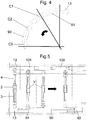
- the figure 4 illustrates an example of a cam for the punch control means.
- the cam shown in plan view comprises a first cam portion 13 (in the direction of rotation of the punches) corresponding to the metering cam, this metering cam 13 being followed by a pressure increase cam portion 91, then of the pressure maintaining cam portion 90.
- the arrow represented on this figure 4 illustrates the direction of movement of the punches on the cam.
- the figure 5 illustrates a device in which the lower control means 7 comprise cams with cam portions similar to the cam shown in FIG. figure 4 that is, a metering cam portion 13, a pressure rise cam portion (91), and a compaction holding cam portion (90).
- the upper control means also includes a planar cam portion (100) for holding the punch in position during compaction, which planar cam is also preceded by a pressure rise cam (101).
- the arrow represented on this figure 5 illustrates the direction of movement of the punches on the cams.
- the figure 5 illustrates a particular embodiment of the press device shown wherein the lower control means 7 and upper 8 both comprise a planar portion for maintaining compaction, and a pressure increase portion.
- the upper punches 4 have a structure similar to the lower punches, and they include in particular preferably at least one roller (43), or even guide rollers (44).
- the upper control means 8 are in this particular case provided with means adapted to retain the upper punches 4 against the effect of gravity.
- the figure 5 also makes it possible to illustrate the movement of the lower and upper punches 4 inside the matrix 2 during their displacement on the cams of the lower and upper control means 7 and 8. It can thus be seen that the volume (V) is progressively reduced when the punches roll on the pressure increase cams (91; 101) while the same containment volume (V) remains fixed (at a compaction volume substantially corresponding to the final volume of the tablet) when the punches roll on the compaction maintaining cams (90; 100).
- At least one of the compaction cams comprises sensors making it possible to follow the compaction stress defined by the action of the lower 3 and upper 4 punches on the mixture of compounds to be compressed. It is also possible to provide distance sensors for monitoring the axial position of the lower and / or upper punches 4.
- these stress sensors are particularly advantageous for monitoring the behavior of the mixture of compounds when it is compacted at a constant volume for a predetermined time.
- these stress sensors can in particular be used to determine and / or adjust the compaction cycle to be applied to the mixture to be compacted.
- the sensor measures the effort of a single punch and the passage of each punch; unlike a stress sensor associated with a compression roller which measures the sum of the forces of the punches in contact with this roller.
- strain sensors can be used to control the proper operation of the press and punches.
- stress sensors can be used to prevent any disturbance of the press, particularly as regards the positioning of the cam paths (parallelism, relative difference, etc.), and / or by controlling the compaction at strategic points. of the compaction cycle.
- the press of the invention for the compaction of pulverulent compositions comprising at least one powder having elastic properties or hot-melt properties, but also to the compaction of pulverulent compositions having a tendency to change state during compaction. for example passing from a solid state to a pasty or liquid state. They may be pulverulent compositions having a high moisture content.
- elastic is meant a material that has the property to take back, partially or totally, its shape or its volume, after having lost by compression or extension.
- hot melt is meant a material that becomes fluid under the effect of heat.
- the press is used to compact powder compositions consisting of a powder or a mixture of powders, at least one of which has elastic or hot-melt properties.
- the press is used for the compaction of pulverulent compositions based on plant materials.
- the compaction can be implemented with plant ingredients such as coffee, tea or chicory or plant ingredients suitable for making herbal teas such as thyme, rosemary, linden, ginseng, ginko, marjoram, mint, verbena, ginger, wild yam, plants of the rosmarinus officinalis family, and mixtures thereof.
- the plant compounds used in the invention are generally in the form of grains or broken or crushed leaves, and having optionally undergone one or more prior treatment known per se.
- the process according to the present invention can in particular be applied to materials such as cellulose, hemicellulose, lignin or any mixture of the above compounds.
- the invention can also be applied to wood fibers, algae, tea, aromatic herbs, stems of dry crushed plants, compost, dried flowers. (to be completed by other plant materials)
- the press is used for the compaction of laundry washing compositions.
- These compositions typically comprise: sequestering agents, alkaline agents, bleaching agents, surfactants (in liquid, solid form, supported on zeolites, bentonites or clays in general) anionic, cationic or nonionic, activators of the bleaching agent, enzymes, splitting agents, perfume binders, dyes, defoamers, optical brighteners, anti-blocking agents color transfer (to be completed by main ingredients) of which (to be supplemented by elastic ingredients) cellulose-type bursting agents have elastic properties, binding agents eg solid polyethylene glycol, solid surfactants type SDS, or supported liquid surfactants on bentonite have hot melt behaviors.
- the press shown is used for the compaction of compositions for washing dishes.
- the presented press makes it possible to progressively compact an initial volume of powder until a desired volume of compaction is reached at which the powder is maintained for a given time. This makes it possible to obtain a solid compact product from a powdery composition.
- the punches are moved by the compaction cam 9 to progressively compact the pulverulent composition to the compaction volume that it is desired to maintain constant.
- the compaction volume is smaller than the initial volume of the uncompacted powder composition.
- the compaction volume is less than or equal to the determined or final volume of the compacted product. Indeed, as has already been said, when the powdery composition is particularly elastic, there may be a slight extension of the product during release of the volume constraint.
- the compaction volume is between 20 and 90% of the initial volume of the pulverulent composition, and preferably between 30 and 75% of the initial volume.
- the particular structure of the press makes it possible to maintain the pulverulent composition at a constant volume which corresponds to the compaction volume for a given time.
- the time at which a constant compaction volume is maintained is chosen according to the characteristics required for the final compacted tablet.
- the hold time can be determined experimentally.
- the press When the compaction volume is kept constant, the press, and more precisely the punches and the associated compaction cams, are subjected to stress stresses due to the strength of the pulverulent composition.
- the resistance of the powdery composition gradually decreases, stress constraints on the press thus decreasing concomitantly.
- the measurement of these stress stresses during constant volume compaction makes it possible to determine the compression curve of a given pulverulent composition and to deduce the minimum time during which the composition must be maintained at the constant compaction volume.
- This measurement can be done on a laboratory press.
- the press according to the invention can also be used to make this particular measurement, provided that there are enough stress sensors arranged in the pressure holding cams.
- roasted and milled coffee of average size 1 mm, with a loss of 4% volatile matter after a stay of 20 minutes at 120 ° C, is compacted using a compaction system to arrive at a constant controlled volume.
- the punch used for this compression is a round punch of diameter 32 mm with chamfer. 7 grams of this product are introduced into the containment chamber representing a filling height of 27.3 mm. The final compression height is set at 8.3 mm leading to a volume reduction of 70%.
- This compression height is maintained for a time of 850 milliseconds.
- the maximum effort measured is 40KN, and only 20 KN after 850 milliseconds of hold time. We can therefore deduce that it is necessary to ensure a holding time in order to obtain a cohesive tablet. In this case the minimum hold time to obtain a cohesive and transportable tablet is 850 milliseconds. At 850 milliseconds the resulting force is 20 KN. The fall of this holding force is equal to 50%.
- the press is dimensioned and / or adjusted so that it can maintain a compaction volume for a time of at least 850 milliseconds, and withstand forces of the order of 40 KN.
- a compression cam having an angular section of at least 56.1 °, for a press having a rotational speed of 11 rpm.
- the punches preferably have a roller having a diameter of 62 mm, and a width of 56 mm.
- the punch used for this compression is a round punch of diameter 32 mm with chamfer. 7 grams of this product are introduced into the containment chamber representing a filling height of 27.3 mm. The final compression height is set at 8.3 mm leading to a volume reduction of 70%. This compression height is maintained for 800 milliseconds.
- the maximum effort measured is 40 KN, and only 20 KN after 800 milliseconds of hold time. We can therefore deduce that it is necessary to ensure a holding time in order to obtain a cohesive tablet.
- the minimum hold time for a cohesive and transportable tablet is 400 milliseconds. At 400 milliseconds the resultant force is 30 KN. The fall of this holding force is equal to 25%.
- the press is dimensioned and / or adjusted so that it can maintain a compaction volume for a time of at least 400 milliseconds, and withstand forces of the order of 40 KN.
- a compression cam having an angular section of at least 43.2 ° is used for a press having a rotation speed of 18 rpm.
- the punches preferably have a roller having a diameter of 62 mm, and a width of 56 mm.
- a Eurotab® linen formulation called 30458 is tested in order to check whether it is necessary to maintain a constant volume maintenance time to obtain a cohesive and transportable tablet.
- the composition to be compacted is indicated in Table 1 below: ⁇ i> Table 1 - composition of laundry formulation 30458 (Eurotab company ⁇ / i> ® ⁇ i>) ⁇ / i> COMPOUNDS % by weight Sequestering agents (phosphates, citrate, polymers, zeolite ”) 35-50% Alkaline agents (sodium silicate, carbonate) 10-30% Charge (bicarbonate, sodium sulfate ...) 3-20% Nonionic and anionic surfactants 10-18% enzymes 0.5-3% Bleaching agents and activator 10-20% Binder (polyethylene glycol powder ...) 1-5% Disintegrating agents (cellulose %) 2-8% Optical brightener 0-1% Anti foam 0-1% perfume 0.5% - 1% dye 0.05% -0.1%
- the press is dimensioned and / or adjusted so that it can maintain a compaction volume for a time of at least 100 milliseconds, and withstand stresses of the order of 32 KN.
- a compression cam having an angular section of at least 10.8 ° is used for a press having a rotation speed of 18 rpm.
- the punches preferably have a roller having a diameter of 62 mm, and a width of 56 mm.
- ARBOCEL TM TF415 (cellulose), marketed by Rettenmaier®, is tested in order to check whether it is necessary to maintain a constant volume hold time to obtain a cohesive and transportable tablet.
- a round punch of diameter 32 mm with chamfer is used. 8.45 grams of this ARBOCEL TM TF415 are introduced into the compaction chamber representing a filling height of 28 mm. The final compression height is fixed at 9 mm, resulting in a volume reduction of 68%. This compression height is maintained for 800 milliseconds. The maximum effort measured is 21 KN, and only 8 KN after 800 milliseconds of hold time. We can therefore deduce that it is necessary to ensure a holding time in order to obtain a cohesive tablet. In this case the minimum hold time to obtain a cohesive and transportable tablet is 300 milliseconds. At 300 milliseconds the resulting force is 18 KN. The fall of this holding force is equal to 14.3%.
- the press is dimensioned and / or adjusted so that it can maintain a compaction volume for a time of at least 300 milliseconds, and withstand stresses of the order of 21 KN.
- a compression cam having an angular section of at least 19.8 ° is used for a press having a rotation speed of 11 rpm.
- the punches preferably have a roller having a diameter of 62 mm, and a width of 56 mm.
- planar cam to maintain compaction is particularly advantageous so that the press has high production rates.
- the use of the planar compacting cam keeps compaction for a relatively long time, for example of the order of 800 ms or even 2500 ms, without the rate of formation of tablets. by the press is reduced.
- the use of holding cams implies that several punches are simultaneously on the cam path, and therefore that several tablets can be compacted simultaneously on the same flat cam portion, with only a slight shift in the compaction cycle.
- Table 2 illustrates the minimum angular sections of the flat cam portion, for different holding times of the constant volume compaction, and for different rotational speeds of the press. These values are of course not limiting and the section of the flat cam portion will be adapted as a function of the desired time to maintain the compaction at a constant volume; the angular section of the flat cam portion can therefore be between these values or be larger, for a given rotation speed. The reasoning is the same if the speed of rotation of the press is changed.
- the sizing of the press and the associated flat cam portion depends on the particular industrial constraints to make the tablets at the desired volume.
- the flat cam portion must have an angular section necessarily less than 180 °, preferably less than 170 °.
- the speed of rotation of the press is then adjusted according to the angular section selected for the flat cam portion to have the desired holding time for constant volume compaction.
- the dimensioning of the flat cam portion can also be imposed by the operating constraints of the press (limiting rotational speeds).
- limiting rotational speeds For a standard production press having a rotation speed of between 18 and 30 revolutions / minute, a flat cam portion having an angular section greater than 3 ° and 5 ° respectively, and preferably greater than 10 °, is used. 18 ° respectively.
- rotational speeds of the press between 18 and 30 rpm are generally preferred to ensure a good rate, it may be necessary to reduce this speed of rotation depending on the composition of the mixture to be compacted, and its behavior at course of compaction.
- speed of rotation of the press it is not uncommon for the speed of rotation of the press to be set around around ten revolutions per minute.
- the press rotates at a speed at least equal to 5 revolutions / minute, and preferably at a speed greater than 8 revolutions / minute.
- a planar cam portion having an angular section of between 5 ° and 170 ° is used, which makes it possible to compact mixtures for compaction keeping times of between 100 and 2500 ms, and this according to a wide range of speed of rotation of the press to ensure a good industrial rate.
- the fact of being able to compact at various speeds of rotation makes it possible to compact any type of mixture during the compaction times indicated (between 100 and 2500 ms), including the mixtures requiring a reduced rotation speed of the press (of the order a dozen revolutions per minute).
- the productivity is even better than such an angular section for the flat cam portion also allows to have a press comprising at least two outputs.
- a flat cam portion having an angular section of between 35 ° and 90 ° is used.
- Such a flat cam makes it possible to compact mixtures during compaction holding times of the order of 800 ms (plus or minus 50 ms) at high rotational speeds of the press. This makes it possible to operate at speeds of between 8 and 18 revolutions / minute, thus offering the possibility of compacting mixtures of various compositions. In addition, it also increases the number of outputs, by putting at least three if desired.
- a press with plane compacting cam portions having an angular section of approximately 52 ° makes it possible to configure the press to have two outputs, with about fifty pairs of punches. circulating at the same time in the press, which allows a production of nearly 1100 tablets of coffee per minute (with a speed of rotation of 11 revolutions / minutes, for a compaction time of about 800 ms).
Description
La présente invention concerne le domaine de la conception de tablettes à partir de mélange de composants, sous forme de poudres ou de granulés notamment, et plus particulièrement un dispositif de presse pour former de telles tablettes par compaction.The present invention relates to the field of tablet design from component mixing, in the form of powders or granules in particular, and more particularly to a press device for forming such tablets by compaction.
Les dispositifs existants pour fabriquer des tablettes par compaction sont classiquement des presses rotatives dotées d'un plateau central rotatif dans lequel est ménagée une pluralité de matrices traversantes. De part et d'autre et en regard de chacune des matrices sont agencés des poinçons inférieur et supérieur complémentaires l'un de l'autre, et destinés à s'insérer dans la matrice correspondante pour venir compacter le mélange qu'elle contient afin de former une tablette compactée au volume désiré. En effet, les poinçons sont dotés d'extrémités de compaction dont les surfaces définissent avec les parois de la matrice un volume de confinement du mélange, les poinçons étant progressivement rapprochés l'un de l'autre jusqu'à atteindre le volume de compaction.The existing devices for making tablets by compaction are conventionally rotary presses provided with a rotating central plate in which is formed a plurality of through dies. On either side and facing each of the matrices are arranged lower and upper punches complementary to each other, and intended to be inserted into the corresponding matrix to compact the mixture it contains in order to form a compacted tablet at the desired volume. Indeed, the punches are provided with compaction ends whose surfaces define with the walls of the matrix a containment volume of the mixture, the punches being progressively closer to each other until reaching the compaction volume.
Ces dispositifs fonctionnent selon un cycle se décomposant comme suit : après une phase de remplissage de la matrice avec le mélange de composés, les poinçons se rapprochent pour contraindre progressivement ledit mélange avant une compaction finale instantanée où les poinçons imposent une contrainte forte sur le mélange de manière former une tablette au volume désiré. Une fois la tablette formée, elle est éjectée de la presse. Pour réaliser un tel cycle de compaction, il est connu d'utiliser des poinçons qui sont guidés dans un rail de guidage ayant un profil particulier pour commander le déplacement axial des poinçons, pendant la phase de remplissage et d'éjection mais aussi pendant la phase de rapprochement des poinçons avant la compaction à proprement parler. La phase de compaction effective est effectuée par des galets de compaction sur lesquels les poinçons roulent, et qui permettent de rapprocher les poinçons instantanément suivant une contrainte forte pour former la tablette au volume désiré. Un dispositif selon le préambule de la revendication 1 est par exemple décrit dans la demande de brevet
Le demandeur a toutefois découvert qu'il pouvait être intéressant, dans certaines applications, de maintenir les poinçons dans une position de compaction fixe de manière à comprimer le mélange à un volume constant pendant un temps de compaction allongé. On se référera utilement à la demande de brevet français déposée le 18 juillet 2008 sous le numéro
Le demandeur a en conséquence cherché à développer une presse rotative permettant de réaliser une telle compaction à volume constant. Pour ce faire il convient de maintenir les poinçons à une position de compaction fixe pour que le volume de confinement (défini par la matrice et les poinçons inférieur et supérieur) soit maintenu constant. Une solution consiste à utiliser un organe de compaction particulier composé de galets de compaction et de roulements à billes agencés de manière à maintenir les poinçons à une position axiale fixe, et à allonger ainsi la compaction. Une telle solution est toutefois complexe à mettre en oeuvre, et elle est peu précise puisque la position axiale des poinçons varie de façon significative par rapport à la position de consigne, en fonction de la surface de contact avec le galet/roulement. En outre, une telle solution n'est pas facilement adaptable, notamment en ce qui concerne le temps de maintien des poinçons.The applicant has therefore sought to develop a rotary press for performing such compaction at constant volume. To do this it is necessary to keep the punches at a fixed compaction position so that the confinement volume (defined by the matrix and the lower and upper punches) is kept constant. One solution is to use a particular compaction member composed of compacting rollers and ball bearings arranged to maintain the punches at a fixed axial position, and to lengthen the compaction. Such a solution is however complex to implement, and it is not very precise since the axial position of the punches varies significantly with respect to the set position, as a function of the contact surface with the roller / bearing. In addition, such a solution is not easily adaptable, particularly as regards the holding time punches.
Un but de la présente invention est donc de proposer une presse adaptée pour maintenir une compaction à un volume constant pendant un temps déterminé permettant de résoudre l'un au moins des inconvénients précités.An object of the present invention is therefore to provide a press adapted to maintain a compaction at a constant volume for a predetermined time to solve at least one of the aforementioned drawbacks.
En particulier, un but de la présente invention est de proposer une presse permettant de maintenir une compaction à volume constant facilement adaptable à tout type de produit, de cadence, et de temps de maintien.In particular, an object of the present invention is to provide a press for maintaining a constant volume compaction easily adaptable to any type of product, rate, and holding time.
Encore un autre but de la présente invention est de proposer une presse permettant de maintenir une compaction à volume constant pouvant être utilisée à des cadences industrielles, pour une productivité accrue, et ce quelque soit le type de produit à compacter.Yet another object of the present invention is to provide a press for maintaining a constant volume compaction that can be used at industrial rates, for increased productivity, and whatever the type of product to compact.
A cette fin, on propose un dispositif de presse pour fabriquer des tablettes à partir d'un mélange d'au moins un composant, selon la revendication 1.For this purpose, there is provided a press device for making tablets from a mixture of at least one component according to
Le fait d'utiliser une portion de came plane ayant une section angulaire comprise entre 5° et 170° est particulièrement avantageux puisque cela permet de compacter des mélanges pendant des temps de maintien en compaction compris entre 100 et 2500 ms, et ce selon une large gamme de vitesse de rotation de la presse permettant d'assurer une bonne cadence industrielle. Le fait de pouvoir compacter selon des vitesses de rotation diverses permet de compacter tout type de mélange pendant les temps de compaction indiqués (entre 100 et 2500 ms), y compris les mélanges nécessitant une vitesse de rotation de la presse réduite (de l'ordre d'une dizaine de tours par minute).The fact of using a planar cam portion having an angular section of between 5 ° and 170 ° is particularly advantageous since it makes it possible to compact mixtures during compaction holding times of between 100 and 2500 ms, and this in a wide range. range of rotational speed of the press to ensure a good industrial rate. The fact of being able to compact at various speeds of rotation makes it possible to compact any type of mixture during the compaction times indicated (between 100 and 2500 ms), including the mixtures requiring a reduced rotation speed of the press (of the order a dozen revolutions per minute).
En outre, la productivité est d'autant meilleure qu'une telle section angulaire pour la portion de came plane permet par ailleurs d'avoir une presse comprenant au moins deux sorties.In addition, the productivity is even better than such an angular section for the flat cam portion also allows to have a press comprising at least two outputs.
Le fait que la portion de came plane ait une certaine longueur implique en outre que plusieurs poinçons sont simultanément sur le chemin de came, ce qui permet d'augmenter encore la cadence de formation de tablettes selon un cycle de compaction ayant une étape de maintien en compaction. En effet, si plusieurs poinçons sont simultanément sur la portion de came plane, cela implique que plusieurs tablettes peuvent être compactées simultanément sur la même portion de came plane avec seulement un léger décalage dans le cycle de compaction.The fact that the planar cam portion has a length furthermore implies that several punches are simultaneously on the cam path, which makes it possible to further increase the rate of formation of tablets according to a compaction cycle having a step of maintaining compaction. Indeed, if several punches are simultaneously on the flat cam portion, this implies that several tablets can be compacted simultaneously on the same flat cam portion with only a slight shift in the compaction cycle.
Des aspects préférés mais non limitatifs du dispositif de presse ci-dessus sont les suivants :
- la portion plane du chemin de came s'étend sur une section angulaire comprise entre 35° et 90° ;
- le chemin de came de la came de compaction comprend en outre une portion de montée en pression située en amont de la portion plane de maintien en compaction, la portion de montée en pression étant adaptée pour déplacer axialement le premier poinçon dans le sens d'une insertion du premier poinçon dans la matrice, vers la position axiale de maintien en compaction ;
- le chemin de came de la came de compaction comprend en outre une portion de descente en pression située en aval de la portion plane de maintien en compaction, la portion de descente en pression étant adaptée pour déplacer axialement le premier poinçon dans le sens d'un retrait du premier poinçon de la matrice, à partir de la position axiale de maintien en compaction ;
- l'organe de guidage comprend deux galets agencés de part et d'autre du premier poinçon de manière à pouvoir rouler dans des gorges agencées de part et d'autre de la trajectoire circulaire définie par le déplacement de la matrice ;
- la came de compaction comprend au moins un capteur de contrainte disposé dans une cavité ménagée dans la came pour mesurer les contraintes subies par le chemin de came au passage du premier poinçon ;
- la came de compaction comprend trois capteurs de contrainte répartis dans trois cavités ménagées dans la came, lesdites trois cavités étant respectivement formées au centre et aux deux extrémités de la portion plane du chemin de came ;
- les deuxièmes moyens de commande ont une configuration identique aux premiers moyens de commande ;
- le deuxième poinçon a une configuration identique au premier poinçon ;
- le premier poinçon et le deuxième poinçon correspondent respectivement au poinçon inférieur et au poinçon supérieur de la presse, les premiers et deuxièmes moyens de commande correspondant aux moyens de commande inférieurs et supérieurs respectivement.
- the flat portion of the cam path extends over an angular section of between 35 ° and 90 °;
- the cam path of the compaction cam further comprises a pressure increase portion located upstream of the planar holding portion in compaction, the pressure increase portion being adapted to axially move the first punch in the direction of a insertion of the first punch in the matrix, towards the axial position of maintaining in compaction;
- the cam path of the compaction cam further comprises a pressure descent portion located downstream of the planar holding portion in compaction, the pressure descent portion being adapted to axially move the first punch in the direction of a removing the first punch from the matrix, from the axial position of maintaining compaction;
- the guide member comprises two rollers arranged on either side of the first punch so as to be able to roll in grooves arranged on either side of the circular path defined by the displacement of the die;
- the compaction cam comprises at least one strain sensor disposed in a cavity formed in the cam for measuring the stresses experienced by the cam path at the passage of the first punch;
- the compaction cam comprises three stress sensors distributed in three cavities formed in the cam, said three cavities being respectively formed at the center and at the two ends of the flat portion of the cam path;
- the second control means have a configuration identical to the first control means;
- the second punch has a configuration identical to the first punch;
- the first punch and the second punch respectively correspond to the lower punch and the upper punch of the press, the first and second control means corresponding to the lower and upper control means respectively.
D'autres caractéristiques et avantages de l'invention ressortiront encore de la description qui suit, laquelle est purement illustrative et non limitative et doit être lue en regard des dessins annexés, sur lesquels :
- La
figure 1 est une représentation tridimensionnelle en coupe d'un dispositif de presse rotative ; - La
figure 2 est un schéma illustrant l'entrainement en rotation des poinçons dans le dispositif de presse rotative ; - la
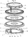
figure 3 est une représentation tridimensionnelle en éclaté du dispositif de presse selon l'invention ; - la
figure 4 est une représentation en vue de dessus d'une came de compaction utilisée pour le dispositif de presse ; - la
figure 5 est une représentation schématique mettant en avant le positionnement des poinçons sur les cames de compaction associées pendant la phase de compaction avec un dispositif de presse selon l'invention ; - la
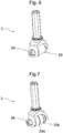
figure 6 est une représentation tridimensionnelle d'un poinçon avec galet de roulement selon un mode particulier de réalisation de l'invention ; - la
figure 7 est une représentation tridimensionnelle d'un poinçon avec galet de roulement selon un autre mode de réalisation de l'invention.
- The
figure 1 is a three-dimensional representation in section of a rotary press device; - The
figure 2 is a diagram illustrating the rotational drive punches in the rotary press device; - the
figure 3 is an exploded three-dimensional representation of the press device according to the invention; - the
figure 4 is a top view of a compaction cam used for the press device; - the
figure 5 is a schematic representation highlighting the positioning of the punches on the compaction cams associated during the compaction phase with a press device according to the invention; - the
figure 6 is a three-dimensional representation of a punch with a roller according to a particular embodiment of the invention; - the
figure 7 is a three-dimensional representation of a punch with a roller according to another embodiment of the invention.
La
Le dispositif de presse rotative comprend une tourelle qui est mise en rotation par un système de motorisation connu par l'intermédiaire d'un axe central d'entrainement. La tourelle comprend un plateau central 1 qui comprend au moins une matrice de compaction 2, cette matrice 2 étant destinée à recevoir un mélange de composés à partir duquel on souhaite former une tablette compactée à un volume déterminé.The rotary press device comprises a turret which is rotated by a known motorization system via a central drive axis. The turret comprises a
Le plateau central comprend de préférence une pluralité de matrices 2 réparties par exemple à la périphérie du plateau central 1 qui a une forme sensiblement circulaire. Lesdites matrices 2 ont une forme généralement cylindrique et sont soit formées par un trou traversant directement ménagé à la périphérie du plateau central 1, soit chaque matrice est une pièce spécifique comprenant une ouverture centrale traversante cylindrique ayant une section circulaire avec un diamètre déterminé correspondant au diamètre recherché pour la tablette, cette pièce servant de matrice ayant une forme externe adaptée pour être insérée dans des ouvertures traversantes ménagées à la périphérie du plateau central 1.The central plate preferably comprises a plurality of
Comme il a été indiqué plus haut, le dispositif de presse comprend des poinçons (non représentés sur la
Les poinçons inférieur 3 et supérieur 4 sont également montés dans la presse de manière à avoir un mouvement circulaire correspondant au mouvement circulaire de la matrice 2 à laquelle ils sont associés. Une solution pour mettre en mouvement les poinçons selon cette trajectoire circulaire est d'utiliser des plateaux d'entrainement 5 et 6 situés de part et d'autre du plateau central 1, ces deux plateaux d'entrainement 5 et 6 étant solidaires du plateau central 1 et étant donc également montés en rotation dans la presse. Les plateaux d'entrainement 5 et 6 sont munis d'ouvertures traversantes disposées à leur périphérie, ces ouvertures traversantes étant destinées à recevoir les poinçons inférieur 3 et supérieur 4 respectivement. Les poinçons inférieur 3 et supérieur 4 sont donc entrainés en rotation par les plateaux d'entrainement 5 et 6 respectivement, de façon synchronisée avec la matrice 2 correspondante, les poinçons inférieur 3 et supérieur 4 pouvant en outre coulisser dans les ouvertures prévues à la périphérie des plateaux d'entrainement 5 et 6 de sorte que les extrémités de compaction 31 et 41 des poinçons inférieur 3 et supérieur 4 puissent être insérées dans la matrice 2.The lower 3 and upper 4 punches are also mounted in the press so as to have a circular movement corresponding to the circular movement of the
Le déplacement axial des poinçons inférieur 3 et supérieur 4 est commandé par des moyens de commande inférieurs 7 et des moyens de commande supérieurs 8 respectivement, ces moyens de commande inférieurs 7 et supérieurs 8 étant destinés à coopérer avec les extrémités de guidage 32 et 42 des poinçons inférieur 3 et supérieur 4 respectivement. Les moyens de commande ont pour objet de déplacer les poinçons correspondants suivant l'axe de la matrice de manière à modifier la position axiale du poinçon (et plus particulièrement la position axiale de l'extrémité de compaction du poinçon) en fonction du cycle de fonctionnement de la presse. La position axiale d'un poinçon se définit comme la position du poinçon dans l'axe de la matrice, cette position permettant ainsi de caractériser le déplacement axial du poinçon, mais également le volume de confinement associé.The axial displacement of the lower 3 and upper 4 punches is controlled by lower control means 7 and upper control means 8 respectively, these lower 7 and upper 8 control means being intended to cooperate with the guide ends 32 and 42 of the punches lower 3 and upper 4 respectively. The control means are intended to move the corresponding punches along the axis of the die so as to modify the axial position of the punch (and more particularly the axial position of the compaction end of the punch) according to the operating cycle of the press. The axial position of a punch is defined as the position of the punch in the axis of the die, this position thus making it possible to characterize the axial displacement of the punch, but also the associated confinement volume.
Parmi les différentes phases du cycle de fonctionnement de la presse, il existe une phase de compaction au cours de laquelle les poinçons inférieur 3 et supérieur 4 sont déplacés de manière à être insérés dans la matrice 2 correspondante pour réduire le volume de confinement, jusqu'à atteindre un volume de compaction que l'on cherche à maintenir constant pendant un certain temps.Among the different phases of the operating cycle of the press, there is a compaction phase during which the lower 3 and upper 4 punches are moved so as to be inserted in the
Les moyens de commande inférieurs 7 et supérieurs 8 sont adaptés pour coopérer de manière à maintenir, pendant un temps déterminé, les poinçons inférieur 3 et supérieur 4 dans une position axiale de compaction fixe dans laquelle ces poinçons inférieur 3 et supérieur 4 définissent avec la matrice 2 associée un volume de confinement fixe correspondant au volume de compaction adapté pour former une tablette avec un certain volume. Pour ce faire, le volume de compaction est sensiblement égal au volume final recherché pour la tablette. De manière préférée, le volume de compaction correspond au volume final recherché pour la tablette. Il peut toutefois dans certains cas être possible que le volume de compaction soit légèrement inférieur au volume final recherché pour la tablette ; c'est par exemple le cas lorsque les composés comprimés sous forme de tablette présentent encore une certaine élasticité.The lower control means 7 and upper 8 are adapted to cooperate so as to maintain, for a predetermined time, the lower 3 and upper 4 punches in an axial fixed compaction position in which these lower 3 and upper 4 punches define with the
Pour ce faire, l'un des deux moyens de commande comprend une came de compaction particulière. Dans la description qui suit, on considère que les moyens de commande inférieurs 7 destinés à déplacer les poinçons inférieurs 3 comprennent ladite came de compaction particulière. Cette description n'est toutefois pas limitative puisqu'une came de compaction telle que décrite ci-après pourrait également être utilisée pour les moyens de commande supérieurs 8, voire à la fois pour les moyens de commande inférieurs 7 et supérieurs 8.To do this, one of the two control means comprises a particular compaction cam. In the following description, it is considered that the lower control means 7 for moving the
La came de compaction 9 comprend un chemin de came sur lequel les poinçons correspondants sont aptes à se déplacer, ce chemin de came ayant une trajectoire correspondant au moins partiellement à la trajectoire circulaire définie par le mouvement des matrices 2.The
Ladite came de compaction 9 comprend une portion plane 90 sensiblement perpendiculaire à l'axe du poinçon 3 qui se déplace sur la came. Ainsi, un poinçon qui se déplace sur cette portion 90 de came plane a une position axiale fixe maintenue pendant un temps déterminé. En effet, la portion plane 90 s'étend sur une section angulaire qui est adaptée pour maintenir le poinçon inséré dans la matrice 2 à la position fixe souhaitée, pour maintenir un volume de compaction constant, pendant un temps de maintien déterminé. On définit la section angulaire de la portion de came plane comme l'angle formé par la portion de came plane par rapport au centre de la trajectoire circulaire des poinçons. On définit par ailleurs la longueur de la portion de came plane comme la distance parcourue par le poinçon sur ladite portion de came plane lorsque le poinçon est entrainé en rotation par le plateau d'entrainement associé.Said
Le dimensionnement de la portion de came plane 90, notamment en ce qui concerne sa section angulaire, dépend du temps pendant lequel on souhaite maintenir constant le volume de compaction, et de la vitesse de rotation à laquelle les poinçons sont entrainés dans la presse. Comme il est mentionné plus loin, le temps de maintien de la compaction à volume constant des systèmes classiques est de moins de 30 ms (millisecondes). Les vitesses de rotation pour une presse rotative utilisée en production sont comprises entre 18 et 30 tours/minute, ce qui correspond à des portions de came plane avec une section angulaire de 3,24° et de 5,4° respectivement, pour un temps de maintien en compaction à volume constant de 30 ms. Si l'on utilise une presse avec une vitesse de rotation plus faible, la section angulaire de la portion de came plane nécessaire à un maintien en compaction à volume constant de 30 ms est réduite ; elle est par exemple de 0,36° pour une vitesse de rotation de 2 tours/minute. La section angulaire de la portion de came plane sera d'autant plus grande que l'on souhaite maintenir longtemps la compaction à volume constant (pour une vitesse de rotation de la presse donnée). On adapte la came de compaction 9, et en particulier la portion 90 de came plane, en fonction du temps pendant lequel on souhaite maintenir la compaction à volume constant, mais également en fonction des paramètres de fonctionnement de la presse (vitesse de rotation, diamètre, etc.). L'utilisation de la portion de came plane pour maintenir un volume de compaction constant est d'autant plus avantageuse qu'il est très simple d'adapter et/ou mettre en place une nouvelle came dans la presse. En outre, on peut également modifier la vitesse de rotation de la presse pour atteindre le temps de maintien désiré pour une portion de came plane ayant une longueur donnée (et donc une section angulaire donnée).The dimensioning of the
Les moyens de commande supérieurs 8 sont également adaptés pour maintenir le poinçon supérieur 4 dans une position axiale fixe pendant que le poinçon inférieur 3 est maintenu en position axiale fixe par coopération avec la portion de came plane 90. Pour ce faire, les moyens de commande supérieurs 8 comprennent une came de compaction 10 ayant une portion de came 100 plane s'étendant sur une section angulaire au moins égale à la section angulaire de la portion de came 90 de la came de compaction 9. Toutefois, dans un exemple ne faisant pas partie de l'invention tout autre moyen permettant de maintenir fixe la position axiale du poinçon supérieur 4 pourra être envisagé. Il pourrait par exemple être utilisé un système de poinçons supérieurs 4 dont le déplacement axial est interdit, les poinçons supérieurs 4 étant alors maintenus dans la matrice 2 à une position axiale fixe définie. Il pourrait également être envisagé d'avoir un dispositif de presse doté uniquement de poinçons inférieurs 3 destinés à être insérés dans des matrices 2 non-traversantes, c'est à dire ayant une ouverture de type « trou borgne ».The upper control means 8 are also adapted to maintain the
Le fait que le poinçon inférieur 3 se déplace sur la portion de came plane 90 pendant un temps déterminé (défini à la fois par la section angulaire sur laquelle s'étend la portion de came plane 90, et par la vitesse de rotation des poinçons) implique que l'extrémité de compaction 31 du poinçon inférieur 3 est maintenu dans la matrice 2 à une position axiale fixe pendant un temps déterminé, l'extrémité de compaction 41 du poinçon supérieur 4 étant également maintenue dans la matrice 2 à une position axiale fixe, de sorte que le poinçon inférieur 3, le poinçon supérieur 4 et la matrice 2 forment un volume de confinement maintenu fixe pendant le même temps déterminé, ce volume de confinement correspondant au volume de compaction adapté pour former la tablette. De manière préférée, on règle les différents organes du dispositif de presse de manière à ce que les poinçons inférieur 3 et supérieur 4 définissent avec la matrice 2, pendant ce temps de maintien en compaction, un volume de compaction fixe correspondant au volume final de la tablette.The fact that the
L'extrémité de guidage 32 du poinçon inférieur 3 est formée pour que ledit poinçon inférieur 3 puisse se déplacer sur la came de compaction 9 de manière à pouvoir répondre aux contraintes de compaction pour former la tablette désirée. Il convient en particulier que les poinçons soient capables de supporter les efforts induits par la compaction du mélange, et que les efforts de frottement soient réduits au maximum. La somme des efforts induits par les poinçons en cours de compaction, génère un couple important au niveau de l'entrainement de la tourelle. L'utilisation de poinçons standards impose le montage d'un moteur avec un couple beaucoup plus important et donc une dimension, des intensités, des puissances beaucoup plus importantes. Le frottement généré par l'ensemble des poinçons dégagent, lorsqu'ils sont standards, une énergie calorifique importante et une dégradation rapide des cames.The
Ainsi, on propose d'utiliser une extrémité de guidage 32 comprenant un galet de roulement 33 agencé de sorte que le poinçon inférieur 3 puisse rouler sur le chemin de came de la came de compaction 9 suivant la trajectoire partiellement circulaire qu'elle définie. Le galet de roulement 33 est agencé coaxialement à l'axe du poinçon inférieur 3 à son extrémité de guidage 32, avec un axe de rotation radial par rapport à l'axe du poinçon L'utilisation d'un tel galet de roulement 33 permet de réduire considérablement les frottements dus au déplacement du poinçon inférieur 3 sur la came de compaction 9, ce qui est particulièrement avantageux pour maintenir des contraintes en compaction importantes, typiquement supérieures à 1 KN (kilo-Newton), pendant des temps de maintien en compaction allongés par rapport aux systèmes classiques de presse rotative. On cherche en effet à maintenir un volume de compaction constant pendant un temps relativement long compris entre 100 ms à 2500 ms par rapport aux systèmes classiques qui effectuent des compactions que l'on peut qualifier d'instantanées (de l'ordre de quelques millisecondes, généralement inférieures à 30 ms).Thus, it is proposed to use a
Le galet de roulement 33 est dimensionné en fonction des contraintes d'effort auquel le dispositif de presse est soumis. Il peut donc être adapté en fonction de la composition du mélange à compacter. Le dimensionnement des galets doit permettre d'accepter les efforts axiaux sans dégrader la surface de came sur laquelle ils roulent (durée de vie compatible avec les aspects de maintenance) tout en permettant un montage de poinçons en nombre suffisant pour conserver une bonne productivité par tour de tourelle. Ainsi, on peut par exemple utiliser des galets de roulement d'un diamètre plus ou moins important, en fonction des contraintes auxquelles le dispositif de presse est soumis pour la compaction d'un mélange déterminé. Lorsque les contraintes d'effort sont importantes, une solution permettant de ne pas avoir un diamètre trop grand pour le galet de roulement, ce qui n'est pas nécessairement compatible avec l'encombrement de la presse, consiste à utiliser pour un poinçon deux galets de roulement (33a, 33b) mis côte à côte. Une telle solution permet d'utiliser des galets de roulement avec des diamètres plus petits pour une même contrainte d'effort, ce qui est donc particulièrement avantageux en termes de compacité de la presse. On peut par exemple utiliser deux galets (33a, 33b) mis côte à côte d'un diamètre de 62 mm, en lieu et place d'un galet de roulement unique d'un diamètre de 110 mm.The rolling
Les deux solutions, à galet de roulement unique et à double galets de roulement, sont illustrées aux
Outre la portion plane 90 correspondant à la phase de maintien en compaction de la phase de compaction, la came de compaction 9 peut en outre comprendre une portion de montée en pression 91 ainsi qu'une portion de descente en pression (non représentée).In addition to the
Si l'on considère le sens de rotation des poinçons, la portion de montée en pression 91 est située en amont de la portion plane 90 de maintien en compaction, cette portion de montée en pression 91 étant adaptée pour déplacer le poinçon inférieur 3 dans le sens d'une insertion dans la matrice 2 jusqu'à atteindre la position axiale correspondant à la position axiale fixe de maintien en compaction définie par la portion plane 90 de maintien en compaction.If we consider the direction of rotation of the punches, the
La portion de montée en pression 91 permet de déplacer progressivement le poinçon inférieur dans la matrice 2, et elle est adaptée pour préparer le mélange à la compaction finale. La came de compaction 9 peut également comprendre une portion de descente en pression située en aval de la portion plane 90 de maintien en compaction, toujours en se référant au sens de rotation des poinçons dans le dispositif de presse. Cette portion de descente en pression 92 a pour objet de réduire le volume de compaction défini par le poinçon inférieur 3, le poinçon supérieur 4 et la matrice 2. Ainsi, cette portion de descente en pression est préférentiellement agencée de manière à déplacer axialement le poinçon inférieur 3 ainsi que le poinçon supérieur 4 en vue d'une extraction de l'extrémité de compaction supérieur 4 de la matrice 2.The pressure rise
Cette portion de descente en pression n'est toutefois pas nécessaire puisque la réduction du volume de confinement (défini par le poinçon inférieur 3, le poinçon supérieur 4 et la matrice 2) peut être effectuée par un déplacement axial du poinçon supérieur 4 en vue de l'extraire de la matrice 2. Selon un mode de réalisation particulier, la portion plane 90 de maintien en compaction de la came de compaction 9 peut même être suivie d'une portion de came 11 agencée pour déplacer axialement le poinçon inférieur 3 pour augmenter son insertion dans la matrice 2. Une telle portion de came 11 peut être qualifiée de came d'extraction, agencée pour expulser en dehors de la matrice 2 la tablette formée pendant la phase de compaction par la came de maintien en compaction 90, de manière à récupérer cette tablette et pour pouvoir remplir de nouveau la matrice 2 avec le mélange de composés avant de reformer une nouvelle tablette.This pressure descent portion is however not necessary since the reduction of the confinement volume (defined by the
Comme on vient de le voir, les moyens de commande inférieurs 7 comprennent outre la came de compaction 9 qui permet de gérer le déplacement axial du poinçon inférieur 3 pendant la phase de compaction à proprement parler, des moyens de guidage permettant de déplacer axialement le poinçon inférieur 3 pendant d'autres phases du cycle de fonctionnement de la presse. La came d'extraction 11 est un exemple particulier de tels moyens de guidage supplémentaire, cette came d'extraction 11 étant utilisée pour pousser la tablette en dehors de la matrice 2 pendant la phase d'extraction suivant la phase de compaction.As we have just seen, the lower control means 7 further comprise the
Les moyens de commande inférieurs peuvent également comprendre une came de dosage avec un chemin de came particulier pour déplacer le poinçon inférieur 3 de manière adéquate pendant le remplissage de la matrice 2 par le mélange de composés. Elle est agencée en amont de la came de compaction 9, de préférence immédiatement avant ladite came de compaction 9.The lower control means may also include a metering cam with a particular cam path for moving the
Les moyens de commande inférieurs 7 peuvent également comprendre d'autres organes de guidage permettant par exemple de déplacer le poinçon inférieur 3 entre les différentes phases importantes du cycle de fonctionnement de la presse, pour mettre les poinçons en position. A cette fin, on pourra par exemple utiliser un ou plusieurs rails de guidage 12 agencés le long de la trajectoire circulaire définie par le déplacement des matrices 2, ces rails étant prévus pour coopérer avec un organe de guidage 34 prévu à l'extrémité de guidage 32 du poinçon inférieur 3. Le poinçon inférieur 3 peut par exemple être muni de galets de guidage 34 agencés coaxialement à l'axe dudit poinçon avec un axe de rotation radial par rapport à ce poinçon, les deux galets de guidage 34 étant situés de part et d'autre du poinçon. Dans ce cas, les rails de guidage 12 sont munis d'une gorge dans laquelle les galets de guidage 34 peuvent rouler. C'est la coopération de ces galets de guidage 34 dans les gorges qui permet de déplacer axialement le poinçon inférieur 3.The lower control means 7 may also comprise other guide members allowing, for example, the
La
La
La
La
Selon un mode de réalisation préféré, l'une des cames de compaction au moins comprend des capteurs permettant de suivre la contrainte en compaction définie par l'action des poinçons inférieur 3 et supérieur 4 sur le mélange de composés à compresser. On peut également prévoir des capteurs de distance permettant de suivre la position axiale des poinçons inférieurs 3 et/ou supérieurs 4.According to a preferred embodiment, at least one of the compaction cams comprises sensors making it possible to follow the compaction stress defined by the action of the lower 3 and upper 4 punches on the mixture of compounds to be compressed. It is also possible to provide distance sensors for monitoring the axial position of the lower and / or
On peut par exemple prévoir de ménager une ou plusieurs cavités dans la portion de came plane pour y insérer des capteurs de contraintes permettant de mesurer les contraintes subies par le chemin de came au passage du poinçon. Cette contrainte peut ensuite être directement liée à la contrainte en compaction imposée au mélange de composés.For example, it is possible to provide one or more cavities in the flat cam portion to insert stress sensors for measuring the stresses to the cam path when the punch passes. This stress can then be directly related to the compaction stress imposed on the mixture of compounds.
Sur les
L'utilisation de ces capteurs de contrainte, notamment les capteurs de contraintes placés dans la portion de came 90 de maintien en compaction, sont particulièrement avantageux pour suivre le comportement du mélange de composés lorsqu'il est compacté à un volume constant pendant un temps déterminé. Comme cela est mentionné plus loin, ces capteurs de contrainte peuvent en particulier être utilisés pour déterminer et/ou régler le cycle de compaction à appliquer au mélange à compacter. Le capteur mesure l'effort d'un seul poinçon et au passage de chaque poinçon ; contrairement à un capteur de contrainte associé à un galet de compression qui mesure la somme des forces des poinçons en contact avec ce galet.The use of these stress sensors, in particular the stress sensors placed in the
En outre, ces capteurs de contrainte peuvent être utilisés pour contrôler le bon fonctionnement de la presse et des poinçons. En particulier, on peut utiliser les capteurs de contraintes pour éviter tout dérèglement de la presse, notamment en ce qui concerne le positionnement des chemins de came (parallélisme, écart relatif, etc.), et/ou en contrôlant la compaction à des points stratégiques du cycle de compaction.In addition, these strain sensors can be used to control the proper operation of the press and punches. In particular, the stress sensors can be used to prevent any disturbance of the press, particularly as regards the positioning of the cam paths (parallelism, relative difference, etc.), and / or by controlling the compaction at strategic points. of the compaction cycle.
On notera que l'utilisation de capteurs de contraintes est indépendant de la longueur choisie pour la portion de came 90 de maintien en compaction, de sorte qu'on peut envisager de disposer de tels capteurs quelle que soit la section angulaire de la portion de came 90 de maintien en compaction.It will be noted that the use of stress sensors is independent of the length chosen for the
Comme il a été indiqué plus haut, le demandeur a découvert qu'il pouvait être intéressant de former des tablettes à partir de certains composés en les maintenant à un volume de compaction constant pendant un temps déterminé, suffisamment long pour que le mélange compacté subisse une transformation physique particulière qui va améliorer de façon significative les propriétés de la tablette, notamment en termes de solidité. Pour plus de détail sur le procédé particulier de compaction qui peut être mis en oeuvre par la presse selon l'invention, on se référera utilement à la demande de brevet français déposée le 18 juillet 2008 sous le numéro
On peut notamment utiliser la presse de l'invention pour la compaction de compositions pulvérulentes comprenant au moins une poudre ayant des propriétés élastiques ou des propriétés thermofusibles, mais aussi à la compaction de compositions pulvérulentes ayant une tendance à changer d'état lors de la compaction passant par exemple d'un état solide à un état pâteux ou liquide. Il peut s'agir de compositions pulvérulentes ayant un forte teneur en humidité. Par « élastique », on entend un matériau qui a la propriété de reprendre, partiellement ou totalement, sa forme ou son volume, après les avoir perdus par compression ou extension. Par « thermofusible », on entend un matériau qui devient fluide sous l'effet de la chaleur.In particular, it is possible to use the press of the invention for the compaction of pulverulent compositions comprising at least one powder having elastic properties or hot-melt properties, but also to the compaction of pulverulent compositions having a tendency to change state during compaction. for example passing from a solid state to a pasty or liquid state. They may be pulverulent compositions having a high moisture content. By "elastic" is meant a material that has the property to take back, partially or totally, its shape or its volume, after having lost by compression or extension. By "hot melt" is meant a material that becomes fluid under the effect of heat.
Dans un mode de réalisation, la presse est utilisée pour compacter des compositions pulvérulentes constituées d'une poudre ou d'un mélange de poudres dont au moins l'une a des propriétés élastiques ou thermofusibles.In one embodiment, the press is used to compact powder compositions consisting of a powder or a mixture of powders, at least one of which has elastic or hot-melt properties.
Dans un mode de réalisation particulier, la presse est utilisée pour la compaction de compositions pulvérulentes à base de matériaux végétaux. La compaction peut être mis en oeuvre avec des ingrédients végétaux tels que du café, du thé ou de la chicorée ou des ingrédients végétaux aptes à faire des tisanes comme le thym, le romarin, le tilleul, le ginseng, le ginko, la marjolaine, la menthe, la verveine, le gingembre, le « wild yam », les plantes de la famille rosmarinus officinalis, et leurs mélanges. Les composés végétaux mis en oeuvre dans l'invention se présentent généralement sous forme de grains ou de feuilles brisés ou broyés, et ayant éventuellement subi un ou plusieurs traitement préalable connus en soi. Le procédé selon la présente invention peut en particulier être appliqué à des matériaux tels que la cellulose, l'hémicellulose, la lignine ou tout mélange des composés précédents. On peut aussi appliquer l'invention aux fibres de bois, algues, thé, herbes aromatiques, tiges de plantes broyées sèches, compost, fleurs séchées. (à compléter par autres matériaux végétaux)In a particular embodiment, the press is used for the compaction of pulverulent compositions based on plant materials. The compaction can be implemented with plant ingredients such as coffee, tea or chicory or plant ingredients suitable for making herbal teas such as thyme, rosemary, linden, ginseng, ginko, marjoram, mint, verbena, ginger, wild yam, plants of the rosmarinus officinalis family, and mixtures thereof. The plant compounds used in the invention are generally in the form of grains or broken or crushed leaves, and having optionally undergone one or more prior treatment known per se. The process according to the present invention can in particular be applied to materials such as cellulose, hemicellulose, lignin or any mixture of the above compounds. The invention can also be applied to wood fibers, algae, tea, aromatic herbs, stems of dry crushed plants, compost, dried flowers. (to be completed by other plant materials)
Dans un autre mode de réalisation de l'invention, la presse est utilisée pour la compaction de compositions pour le lavage du linge de type lessive. Ces compositions comprennent typiquement : des agents séquestrants, des agents alcalins, des agents de blanchiment, des tensioactifs (sous forme liquide, solide, supportée sur des zéolites, bentonites ou des argiles en général) anioniques, cationiques ou non ioniques , des activateurs de l'agent blanchiment, des enzymes, des agents d'éclatement, des agents liants des parfums, des colorants, des antimousses, des azurants optiques, des agents anti transfert de couleur(à compléter par ingrédients principaux) dont (à compléter par ingrédients élastiques) les agents d'éclatement type cellulose ont des propriétés élastiques, les agents liants exemple les polyethylène glycol solides, les tensioactifs solides type SDS, ou les tensioactifs liquides supportés sur bentonite ont des comportements thermofusibles.In another embodiment of the invention, the press is used for the compaction of laundry washing compositions. These compositions typically comprise: sequestering agents, alkaline agents, bleaching agents, surfactants (in liquid, solid form, supported on zeolites, bentonites or clays in general) anionic, cationic or nonionic, activators of the bleaching agent, enzymes, splitting agents, perfume binders, dyes, defoamers, optical brighteners, anti-blocking agents color transfer (to be completed by main ingredients) of which (to be supplemented by elastic ingredients) cellulose-type bursting agents have elastic properties, binding agents eg solid polyethylene glycol, solid surfactants type SDS, or supported liquid surfactants on bentonite have hot melt behaviors.
Selon encore un autre mode de réalisation de l'invention, la presse présentée est utilisée pour la compaction de compositions pour le lavage de la vaisselle.According to yet another embodiment of the invention, the press shown is used for the compaction of compositions for washing dishes.
La presse présentée permet de compacter progressivement un volume initial de poudre jusqu'à atteindre un volume de compaction désiré auquel la poudre est maintenu pendant un temps donné. Cela permet d'obtenir un produit compact solide à partir d'une composition pulvérulente.The presented press makes it possible to progressively compact an initial volume of powder until a desired volume of compaction is reached at which the powder is maintained for a given time. This makes it possible to obtain a solid compact product from a powdery composition.
Une fois avoir inséré le mélange dans la matrice, les poinçons sont déplacés par la came de compaction 9 pour compacter progressivement la composition pulvérulente jusqu'à le volume de compaction que l'on veut maintenir constant. Le volume de compaction est inférieur au volume initial de la composition pulvérulente non compactée. Par ailleurs, le volume de compaction est inférieur ou égal au volume déterminé ou final du produit compacté. En effet, comme on l'a déjà dit, lorsque la composition pulvérulente est particulièrement élastique, il peut y avoir une légère extension du produit lors du relâchement de la contrainte de volume. Dans un mode de réalisation avantageux, le volume de compaction est compris entre 20 et 90% du volume initial de la composition pulvérulente, et préférentiellement entre 30 et 75% du volume initial.Once the mixture has been inserted into the matrix, the punches are moved by the
La structure particulière de la presse permet de maintenir la composition pulvérulente à un volume constant qui correspond au volume de compaction pendant un temps donné. Le temps auquel on maintient un volume de compaction constant est choisi en fonctions des caractéristiques requises pour la tablette finale compactée. Le temps de maintien peut être déterminé expérimentalement.The particular structure of the press makes it possible to maintain the pulverulent composition at a constant volume which corresponds to the compaction volume for a given time. The time at which a constant compaction volume is maintained is chosen according to the characteristics required for the final compacted tablet. The hold time can be determined experimentally.
Lorsque le volume de compaction est maintenu constant, la presse, et plus précisément les poinçons et les cames de compaction associées, sont soumis à des contraintes d'effort dues à la résistance de la composition pulvérulente. Au cours de l'étape de compaction à volume constant, la résistance de la composition pulvérulente diminue progressivement, les contraintes d'effort sur la presse diminuant donc de façon concomitante.When the compaction volume is kept constant, the press, and more precisely the punches and the associated compaction cams, are subjected to stress stresses due to the strength of the pulverulent composition. During the compaction step at constant volume, the resistance of the powdery composition gradually decreases, stress constraints on the press thus decreasing concomitantly.
La mesure de ces contraintes d'effort pendant la compaction à volume constant permet de déterminer la courbe de compression d'une composition pulvérulente donnée et d'en déduire le temps minimal pendant lequel la composition doit être maintenue au volume de compaction constant. Cette mesure peut se faire sur une presse de laboratoire. La presse selon l'invention peut également être utilisée pour faire cette mesure particulière, sous réserve qu'il y ait suffisamment de capteurs de contrainte agencés dans les cames de maintien en pression. En pratique, on pourra utiliser trois capteurs de contrainte placés dans la portion de came 90 de maintien en compaction, respectivement au début, au centre, et à la fin de la portion de came 90 de maintien en compaction, c'est-à-dire aux deux extrémités et au centre de la portion de came 90 de maintien en compaction. On peut également utiliser la presse selon l'invention pour confirmer les résultats du laboratoire, et/ou vérifier que le comportement du mélange compacté est semblable en conditions industrielles.The measurement of these stress stresses during constant volume compaction makes it possible to determine the compression curve of a given pulverulent composition and to deduce the minimum time during which the composition must be maintained at the constant compaction volume. This measurement can be done on a laboratory press. The press according to the invention can also be used to make this particular measurement, provided that there are enough stress sensors arranged in the pressure holding cams. In practice, it will be possible to use three strain sensors placed in the
Une fois que le temps minimum pour le maintien à volume constant est déterminé, il convient de régler la presse pour qu'elle soit adaptée à ces conditions de compaction, voire à dimensionner la came de compaction 9 (plus précisément la portion plane de maintien en compaction 90) et/ou les galets de roulement des poinçons.Once the minimum time for maintenance at constant volume is determined, it is necessary to adjust the press so that it is adapted to these compaction conditions, or even to size the compaction cam 9 (more precisely the plane holding portion in compaction 90) and / or the rollers of the punches.
On trouve ci-dessous des exemples illustrant la détermination du temps de maintien en compression, et le dimensionnement de la presse correspondant, pour différentes compositions à compacter.Below are examples illustrating the determination of the holding time in compression, and the sizing of the corresponding press, for different compositions to be compacted.
Du café rôti et moulu en grain de taille moyenne 1 mm, et ayant une perte en matières volatiles de 4 % après un séjour de 20 mn à 120°C, est compacté à l'aide d'un système de compactage permettant d'arriver à un volume constant contrôlé. Le poinçon utilisé pour cette compression est un poinçon rond de diamètre 32 mm avec chanfrein. 7 grammes de ce produit sont introduits dans la chambre de confinement représentant une hauteur de remplissage de 27,3 mm. La hauteur de compression finale est fixée à 8,3 mm conduisant à une réduction de volume de 70%. Cette hauteur de compression est maintenue pendant un temps de 850 millisecondes. L'effort maximal mesuré est de 40KN, et seulement de 20 KN après les 850 millisecondes de temps de maintien. Nous pouvons donc en déduire qu'il est nécessaire d'assurer un temps de maintien afin d'obtenir une tablette cohésive. Dans le cas présent le temps de maintien minimum pour obtenir une tablette cohésive et transportable est de 850 millisecondes. A 850 millisecondes la force résultante est de 20 KN. La chute de cette force de maintien est égale à 50%.Roasted and milled coffee of
On dimensionne et/ou règle donc la presse pour qu'elle puisse maintenir un volume de compaction pendant un temps d'au moins 850 millisecondes, et à résister à des efforts de l'ordre de 40 KN. Pour ce faire, on utilise une came de compression ayant une section angulaire d'au moins 56,1°, pour une presse ayant une vitesse de rotation de 11 tours/minute. En outre les poinçons ont préférentiellement un galet de roulement ayant un diamètre de 62 mm, et une largeur de 56 mm.The press is dimensioned and / or adjusted so that it can maintain a compaction volume for a time of at least 850 milliseconds, and withstand forces of the order of 40 KN. To do this, a compression cam having an angular section of at least 56.1 °, for a press having a rotational speed of 11 rpm. In addition, the punches preferably have a roller having a diameter of 62 mm, and a width of 56 mm.
Du café rôti et moulu en grain de taille moyenne 1 mm, et ayant une perte en matières volatiles de 3,3 % après un séjour de 20 mn à 120°C, est compacté à l'aide d'un système de compactage permettant d'arriver à un volume constant contrôlé. Le poinçon utilisé pour cette compression est un poinçon rond de diamètre 32 mm avec chanfrein. 7 grammes de ce produit sont introduits dans la chambre de confinement représentant une hauteur de remplissage de 27,3 mm. La hauteur de compression finale est fixée à 8,3 mm conduisant à une réduction de volume de 70%. Cette hauteur de compression est maintenue pendant un temps de 800 millisecondes. L'effort maximal mesuré est de 40 KN, et seulement de 20 KN après les 800 millisecondes de temps de maintien. Nous pouvons donc en déduire qu'il est nécessaire d'assurer un temps de maintien afin d'obtenir une tablette cohésive. Dans le cas présent le temps de maintien minimum pour obtenir une tablette cohésive et transportable est de 400 millisecondes. A 400 millisecondes la force résultante est de 30 KN. La chute de cette force de maintien est égale à 25%.Ground roasted and ground coffee of
On dimensionne et/ou règle donc la presse pour qu'elle puisse maintenir un volume de compaction pendant un temps d'au moins 400 millisecondes, et à résister à des efforts de l'ordre de 40 KN. Pour ce faire, on utilise une came de compression ayant une section angulaire d'au moins 43,2°, pour une presse ayant une vitesse de rotation de 18 tours/minute. En outre les poinçons ont préférentiellement un galet de roulement ayant un diamètre de 62 mm, et une largeur de 56 mm.The press is dimensioned and / or adjusted so that it can maintain a compaction volume for a time of at least 400 milliseconds, and withstand forces of the order of 40 KN. To do this, a compression cam having an angular section of at least 43.2 ° is used for a press having a rotation speed of 18 rpm. In addition, the punches preferably have a roller having a diameter of 62 mm, and a width of 56 mm.
Une formulation linge de la société Eurotab® dénommée 30458 est testée afin de vérifier s'il est nécessaire de maintenir un temps de maintien à volume constant pour obtenir une tablette cohésive et transportable. La composition à compacter est indiquée dans le Tableau 1 ci-dessous :
Pour ce test un poinçon rond de diamètre 45 mm avec chanfrein, poinçon standard pour l'application tablette linge, est utilisé. 40 grammes de cette formulation 30458 sont introduits dans la chambre de compaction représentant une hauteur de remplissage de 38 mm. La hauteur de compression finale est fixée 18 mm conduisant à une réduction de volume de 53%. Cette hauteur de compression est maintenue pendant un temps de 800 millisecondes. L'effort maximal mesuré est de 31,5 KN, et seulement de 18 KN après les 800 millisecondes de temps de maintien. Nous pouvons donc en déduire qu'il est nécessaire d'assurer un temps de maintien afin d'obtenir une tablette cohésive. Dans le cas présent le temps de maintien minimum pour obtenir une tablette cohésive et transportable est de 100 millisecondes. A 112 millisecondes la force résultante est de 28KN. La chute de cette force de maintien est égale à 11%.For this test a round punch 45 mm in diameter with chamfer, standard punch for tablet application, is used. 40 grams of this formulation 30458 are introduced into the compaction chamber representing a filling height of 38 mm. The final compression height is set at 18 mm, resulting in a volume reduction of 53%. This compression height is maintained for 800 milliseconds. The maximum effort measured is 31.5 KN, and only 18 KN after 800 milliseconds of hold time. We can therefore deduce that it is necessary to ensure a holding time in order to obtain a cohesive tablet. In this case the minimum hold time to obtain a cohesive and transportable tablet is 100 milliseconds. At 112 milliseconds the resultant force is 28KN. The fall of this holding force is equal to 11%.
On dimensionne et/ou règle donc la presse pour qu'elle puisse maintenir un volume de compaction pendant un temps d'au moins 100 millisecondes, et à résister à des efforts de l'ordre de 32 KN. Pour ce faire, on utilise une came de compression ayant une section angulaire d'au moins 10,8°, pour une presse ayant une vitesse de rotation de 18 tours/minute. En outre les poinçons ont préférentiellement un galet de roulement ayant un diamètre de 62 mm, et une largeur de 56 mm.The press is dimensioned and / or adjusted so that it can maintain a compaction volume for a time of at least 100 milliseconds, and withstand stresses of the order of 32 KN. To do this, a compression cam having an angular section of at least 10.8 ° is used for a press having a rotation speed of 18 rpm. In addition, the punches preferably have a roller having a diameter of 62 mm, and a width of 56 mm.
L'ARBOCEL™ TF415 (cellulose), commercialisée par la société Rettenmaier®, est testée afin de vérifier s'il est nécessaire de maintenir un temps de maintien à volume constant pour obtenir une tablette cohésive et transportable. Pour ce test un poinçon rond de diamètre 32 mm avec chanfrein est utilisé. 8,45 grammes de cet ARBOCEL™ TF415 sont introduits dans la chambre de compaction représentant une hauteur de remplissage de 28 mm. La hauteur de compression finale est fixée 9 mm conduisant à une réduction de volume de 68%. Cette hauteur de compression est maintenue pendant un temps de 800 millisecondes. L'effort maximal mesuré est de 21 KN, et seulement de 8 KN après les 800 millisecondes de temps de maintien. Nous pouvons donc en déduire qu'il est nécessaire d'assurer un temps de maintien afin d'obtenir une tablette cohésive. Dans le cas présent le temps de maintien minimum pour obtenir une tablette cohésive et transportable est de 300 millisecondes. A 300 millisecondes la force résultante est de 18 KN. La chute de cette force de maintien est égale à 14,3%.ARBOCEL ™ TF415 (cellulose), marketed by Rettenmaier®, is tested in order to check whether it is necessary to maintain a constant volume hold time to obtain a cohesive and transportable tablet. For this test a round punch of
On dimensionne et/ou règle donc la presse pour qu'elle puisse maintenir un volume de compaction pendant un temps d'au moins 300 millisecondes, et à résister à des efforts de l'ordre de 21 KN. Pour ce faire, on utilise une came de compression ayant une section angulaire d'au moins 19.8°, pour une presse ayant une vitesse de rotation de 11 tours/minute. En outre les poinçons ont préférentiellement un galet de roulement ayant un diamètre de 62 mm, et une largeur de 56 mm.The press is dimensioned and / or adjusted so that it can maintain a compaction volume for a time of at least 300 milliseconds, and withstand stresses of the order of 21 KN. To do this, a compression cam having an angular section of at least 19.8 ° is used for a press having a rotation speed of 11 rpm. In addition, the punches preferably have a roller having a diameter of 62 mm, and a width of 56 mm.
Le fait d'utiliser une came plane pour le maintien en compaction est particulièrement avantageux pour que la presse présente des cadences de production importantes. En effet, l'utilisation de la came plane de maintien en compaction permet de maintenir la compaction pendant un temps relativement long, par exemple de l'ordre de 800 ms, voire de 2500 ms, sans pour autant que la cadence de formation de tablettes par la presse soit réduite. En effet, l'utilisation de cames de maintien implique que plusieurs poinçons sont simultanément sur le chemin de came, et donc que plusieurs tablettes peuvent être compactées simultanément sur la même portion de came plane, avec seulement un léger décalage dans le cycle de compaction.The fact of using a planar cam to maintain compaction is particularly advantageous so that the press has high production rates. Indeed, the use of the planar compacting cam keeps compaction for a relatively long time, for example of the order of 800 ms or even 2500 ms, without the rate of formation of tablets. by the press is reduced. Indeed, the use of holding cams implies that several punches are simultaneously on the cam path, and therefore that several tablets can be compacted simultaneously on the same flat cam portion, with only a slight shift in the compaction cycle.
Le tableau 2 ci-dessous illustre les sections angulaires minimales de la portion de came plane, pour différents temps de maintien de la compaction à volume constant, et pour différentes vitesses de rotation de la presse. Ces valeurs ne sont bien entendues pas limitatives et on adaptera la section de la portion de came plane en fonction du temps désiré pour maintenir la compaction à volume constant ; la section angulaire de la portion de came plane pourra donc être comprise entre ces valeurs ou être plus grande, pour une vitesse de rotation donnée. Le raisonnement est identique si l'on modifie la vitesse de rotation de la presse.
Le dimensionnement de la presse et de la portion de came plane associée dépend des contraintes industrielles particulières pour fabriquer les tablettes au volume désiré.The sizing of the press and the associated flat cam portion depends on the particular industrial constraints to make the tablets at the desired volume.
Il pourra par exemple être décidé de faire une presse avec deux sorties (c'est à dire qu'il est formé deux tablettes par tour pour un même ensemble matrice/poinçons) de sorte que la portion de came plane doit avoir une section angulaire nécessairement inférieure à 180°, préférentiellement inférieure à 170°. On règle ensuite la vitesse de rotation de la presse en fonction de la section angulaire choisie pour la portion de came plane pour avoir le temps de maintien désiré pour la compaction à volume constant.It may for example be decided to make a press with two outputs (that is to say it is formed two tablets per turn for the same set matrix / punches) so that the flat cam portion must have an angular section necessarily less than 180 °, preferably less than 170 °. The speed of rotation of the press is then adjusted according to the angular section selected for the flat cam portion to have the desired holding time for constant volume compaction.
Le dimensionnement de la portion de came plane peut également être imposé par les contraintes de fonctionnement de la presse (vitesses de rotation limites). Ainsi, pour une presse standard de production ayant une vitesse de rotation comprise entre 18 et 30 tours/minute, on utilise une portion de came plane ayant une section angulaire supérieure à 3° et 5° respectivement, et de préférence supérieure à 10° et 18° respectivement.The dimensioning of the flat cam portion can also be imposed by the operating constraints of the press (limiting rotational speeds). Thus, for a standard production press having a rotation speed of between 18 and 30 revolutions / minute, a flat cam portion having an angular section greater than 3 ° and 5 ° respectively, and preferably greater than 10 °, is used. 18 ° respectively.
Si des vitesses de rotation de la presse comprises entre 18 et 30 tours/minute sont généralement préférées pour assurer une bonne cadence, il peut être nécessaire de diminuer cette vitesse de rotation en fonction de la composition du mélange à compacter, et de son comportement au cours de la compaction. Ainsi, il n'est pas rare que la vitesse de rotation de la presse soit fixée aux alentours d'une dizaine de tours par minute. Pour maintenir une cadence industrielle acceptable, il est tout de même préférable que la presse tourne à une vitesse au moins égale à 5 tours/minute, et préférentiellement à une vitesse supérieure à 8 tours/minute.If rotational speeds of the press between 18 and 30 rpm are generally preferred to ensure a good rate, it may be necessary to reduce this speed of rotation depending on the composition of the mixture to be compacted, and its behavior at course of compaction. Thus, it is not uncommon for the speed of rotation of the press to be set around around ten revolutions per minute. To maintain an acceptable industrial rate, it is still preferable that the press rotates at a speed at least equal to 5 revolutions / minute, and preferably at a speed greater than 8 revolutions / minute.
De manière préférée, on utilise une portion de came plane ayant une section angulaire comprise entre 5° et 170° ce qui permet de compacter des mélanges pendant des temps de maintien en compaction compris entre 100 et 2500 ms, et ce selon une large gamme de vitesse de rotation de la presse permettant d'assurer une bonne cadence industrielle. Le fait de pouvoir compacter selon des vitesses de rotation diverses permet de compacter tout type de mélange pendant les temps de compaction indiqués (entre 100 et 2500 ms), y compris les mélanges nécessitant une vitesse de rotation de la presse réduite (de l'ordre d'une dizaine de tours par minute). En outre, la productivité est d'autant meilleure qu'une telle section angulaire pour la portion de came plane permet par ailleurs d'avoir une presse comprenant au moins deux sorties.Preferably, a planar cam portion having an angular section of between 5 ° and 170 ° is used, which makes it possible to compact mixtures for compaction keeping times of between 100 and 2500 ms, and this according to a wide range of speed of rotation of the press to ensure a good industrial rate. The fact of being able to compact at various speeds of rotation makes it possible to compact any type of mixture during the compaction times indicated (between 100 and 2500 ms), including the mixtures requiring a reduced rotation speed of the press (of the order a dozen revolutions per minute). In addition, the productivity is even better than such an angular section for the flat cam portion also allows to have a press comprising at least two outputs.
De manière encore préférée, on utilise une portion de came plane ayant une section angulaire comprise entre 35° et 90°. Une telle came plane permet en effet de compacter des mélanges pendant des temps de maintien en compaction de l'ordre de 800 ms (plus ou moins 50 ms) à des vitesses de rotation de la presse élevées. Cela permet en effet de fonctionner à des vitesses comprises entre 8 et 18 tours/minutes, offrant ainsi la possibilité de compacter des mélanges de compositions diverses. Par ailleurs, cela permet également d'augmenter le nombre de sorties, en en mettant au moins trois si cela est désiré.Still more preferably, a flat cam portion having an angular section of between 35 ° and 90 ° is used. Such a flat cam makes it possible to compact mixtures during compaction holding times of the order of 800 ms (plus or minus 50 ms) at high rotational speeds of the press. This makes it possible to operate at speeds of between 8 and 18 revolutions / minute, thus offering the possibility of compacting mixtures of various compositions. In addition, it also increases the number of outputs, by putting at least three if desired.
A titre illustratif de ces avantages en termes de productivité, une presse avec des portions de came plane de maintien en compaction ayant une section angulaire d'environ 52°, permet de configurer la presse pour avoir deux sorties, avec une cinquantaine de paires de poinçons circulant en même temps dans la presse, ce qui permet une production de près de 1100 tablettes de café par minute (avec une vitesse de rotation de 11 tours/minutes, pour un temps de maintien en compaction d'environ 800 ms).As an illustration of these advantages in terms of productivity, a press with plane compacting cam portions having an angular section of approximately 52 °, makes it possible to configure the press to have two outputs, with about fifty pairs of punches. circulating at the same time in the press, which allows a production of nearly 1100 tablets of coffee per minute (with a speed of rotation of 11 revolutions / minutes, for a compaction time of about 800 ms).
Le lecteur aura compris que de nombreuses modifications peuvent être apportées sans sortir matériellement des nouveaux enseignements et des avantages décrits ici. Par conséquent, toutes les modifications de ce type sont destinées à être incorporées à l'intérieur de la portée du dispositif de presse selon l'invention.The reader will understand that many changes can be made without materially escaping the new lessons and benefits described here. Therefore, all modifications of this type are intended to be incorporated within the scope of the press device according to the invention.
Claims (10)
- A press device for manufacturing tablets from a powdery composition comprising at least one powder having elastic properties or thermofusible properties, comprising:- a turntable (1) in which is arranged at least one die (2) for receiving the powdery composition,- at least one compaction assembly comprising a first punch (3) and a second punch (4), said first and second punches being laid out on either side of the turntable (1) facing the die (2), and being mounted so as to be translationally mobile coaxially with the die (2),- first control means (7) and second control means (8) for controlling the axial displacement of the first punch (3) and of the second punch (4) respectively, said first (7) and second (8) control means comprising means co-operating for maintaining the first (3) and second (4) punches in a fixed axial position in which the first (3) and second (4) punches define a confinement volume (V) with the die (2),wherein the first control means (7) comprise a first compaction cam (9) for displacing the first punch (3) into the compaction position and the second control means (8) comprise a second compaction cam (10) for displacing the second punch (4) into the compaction position,- said first compaction cam (9) comprising a cam path on which said first punch (3) is capable of being displaced, the cam path comprising a first planar portion (90) perpendicular to the axis of the first punch (3),- said second compaction cam (10) comprising a cam path on which said second punch (4) is capable of being displaced, the cam path comprising a second planar portion (100) perpendicular to the axis of the second punch (4), the second planar portion (100) extending over an angular section at least equal to the angular section of the first planar portion (90) of the first compaction cam (9) for maintaining the second punch in said die at a fixed compaction axial position at least during said compaction-maintaining time,characterized in that the first planar portion (90) extends over an angular section comprised between 5° and 170° for maintaining the first punch (3) in the die (2) at a fixed compaction axial position during a compaction-maintaining time comprised between 100 ms and 2500 ms, the second planar portion (100) extending over an angular section at least equal to the angular section of the first planar portion (90) of the first compaction cam (9) for maintaining the second punch in said die at a fixed compaction axial position at least during said compaction-maintaining time, the first planar portion (90) and the second planar portion (100) being arranged relative to one another so as to maintain, during said compaction-maintaining time, the confinement volume (V) at a constant volume corresponding to the compaction volume for forming the tablet,
and in that the first punch (3) comprises at least one bearing roller (33) arranged so as to allow both rolling of the first punch (3) on the cam path of the compaction cam (9) according to the direction of rotation of the turntable (1) and an axial displacement of said first punch (3), said bearing roller (33) being laid out at one end of the first punch (3) coaxially with the axis of said first punch (3), with a radial axis of rotation relatively to said first punch (3), and the first punch (3) further comprising a guiding member (34) extending radially relatively to said first punch (3), the first control means (7) comprising at least one guide rail (12) provided with a groove arranged for receiving said guiding member (34). - The device of claim 1, wherein the planar portion (90) of the cam path extends over an angular section comprised between 35° and 90°.
- The device of any one of claims 1 to 2, wherein the cam path of the compaction cam (9) further comprises a pressure rising portion (91) located upstream from the planar compaction-maintaining portion (90), the pressure rising portion (91) being designed so as to axially displace the first punch (3) in the direction of insertion of the first punch (3) into the die (2), towards the axial compaction-maintaining position.
- The device of any one of claims 1 to 3 wherein the cam path of the compaction cam further comprises a pressure lowering portion located downstream from the planar compaction-maintaining portion (90), the pressure lowering portion being designed for axially displacing the first punch (3) in the direction of withdrawal of the first punch (3) of the die (2), from the axial compaction-maintaining position.
- The device of any one of claims 1 to 4, wherein the guiding member (34) comprises two rollers (34) laid out on either side of the first punch (3) so as to be able to roll in the grooves laid out on either side of the circular trajectory defined by the displacement of the die (2).
- The device of any one of claims 1 to 5, wherein the compaction cam (9) comprises at least one stress sensor (C1;C2;C3) positioned in a cavity made in the cam (9) for measuring the stresses undergone by the cam path upon the passing of the first punch (3).
- The device of claim 6, wherein the compaction cam (9) comprises three stress sensors (C1;C2;C3) distributed in three cavities made in the cam (9), said three cavities being formed at the center and at the two ends of the planar portion (90) of the cam path, respectively.
- The device of any one of claims 1 to 7, wherein the second control means (8) have a configuration identical with the first control means (7).
- The device of any one of claims 1 to 8, wherein the second punch (4) has a configuration identical with the first punch (3).
- The device of any one of claims 1 to 9, wherein the first punch (3) and the second punch (4) respectively correspond to the lower punch (3) and to the upper punch (4) of the press, the first (7) and second (8) control means corresponding to the lower (7) and upper (8) control means, respectively.
Applications Claiming Priority (2)
| Application Number | Priority Date | Filing Date | Title |
|---|---|---|---|
| FR0854917A FR2933897B1 (en) | 2008-07-18 | 2008-07-18 | DEVICE FOR FORMING TABLETS BY CONSTANT VOLUME COMPACTION |
| PCT/EP2009/059205 WO2010007152A1 (en) | 2008-07-18 | 2009-07-17 | Device for forming tablets by constant volume compaction |
Publications (2)
| Publication Number | Publication Date |
|---|---|
| EP2313259A1 EP2313259A1 (en) | 2011-04-27 |
| EP2313259B1 true EP2313259B1 (en) | 2017-05-24 |
Family
ID=40380667
Family Applications (1)
| Application Number | Title | Priority Date | Filing Date |
|---|---|---|---|
| EP09780753.1A Not-in-force EP2313259B1 (en) | 2008-07-18 | 2009-07-17 | Device for forming tablets by constant volume compaction |
Country Status (7)
| Country | Link |
|---|---|
| US (2) | US8764430B2 (en) |
| EP (1) | EP2313259B1 (en) |
| JP (1) | JP2011528282A (en) |
| BR (1) | BRPI0916227A2 (en) |
| CA (1) | CA2730157C (en) |
| FR (1) | FR2933897B1 (en) |
| WO (1) | WO2010007152A1 (en) |
Families Citing this family (7)
| Publication number | Priority date | Publication date | Assignee | Title |
|---|---|---|---|---|
| US8647567B2 (en) | 2011-04-06 | 2014-02-11 | The Clorox Company | Methods of providing uniform delivery of a functional agent from a shaped composition |
| FR2990377B1 (en) * | 2012-05-11 | 2015-03-13 | Eurotab | PUNCH HOLDER FOR COMPACTION MACHINE |
| FR3008405A1 (en) | 2013-07-15 | 2015-01-16 | Lhoist Rech & Dev Sa | COMPOSITION COMPRISING CALCO MAGNEI COMPOUNDS IN THE FORM OF COMPACTS |
| ITMO20130324A1 (en) | 2013-11-29 | 2015-05-30 | Sacmi | FORMING APPARATUS |
| DE102017130885B4 (en) * | 2017-12-21 | 2020-01-23 | Fette Compacting Gmbh | Method for regulating the rotor speed of a rotor of a rotary tablet press and rotary tablet press |
| CN108572602B (en) * | 2018-07-23 | 2024-03-15 | 上海海得控制系统股份有限公司 | Control device of tablet press |
| US20230001663A1 (en) * | 2021-07-02 | 2023-01-05 | Industrial Pharmaceutical Resources, Inc. | Rotary tablet press with multiple row turret |
Citations (3)
| Publication number | Priority date | Publication date | Assignee | Title |
|---|---|---|---|---|
| US4121289A (en) * | 1975-05-28 | 1978-10-17 | Hoffmann-La Roche Inc. | Method invoking tabletting compression force control for optimizing tabletted formulation parameters |
| FR2629712A1 (en) * | 1988-04-08 | 1989-10-13 | Bordeaux Ii Inst Pharmacie Ind | Device making it possible to improve the mechanical characteristics of tablets obtained on machines with a high turnover rate |
| GB2343862A (en) * | 1998-11-18 | 2000-05-24 | Univ Bath | A part for use in a moulding apparatus |
Family Cites Families (20)
| Publication number | Priority date | Publication date | Assignee | Title |
|---|---|---|---|---|
| GB174657A (en) | 1920-07-30 | 1922-01-30 | Maschinelle Druckentwaesserung | Improvements in presses for briquetting or drying |
| CH103284A (en) * | 1923-02-20 | 1924-02-01 | A Th Dr Gaillard | Pellet press. |
| FR724379A (en) * | 1931-09-21 | 1932-04-26 | Improvements in the manufacture of articles molded with synthetic resin or the like | |
| CH200650A (en) * | 1937-03-20 | 1938-10-31 | Sen Albert Henkel | Machine for the production of plastic candy. |
| SU599993A1 (en) * | 1976-10-11 | 1978-03-30 | Ждановский Филиал Специального Проектно-Технологического Бюро Медицинской Промышленности | Rotary machine |
| JPS5440371A (en) * | 1977-09-06 | 1979-03-29 | Hitachi Funmatsu Yakin Kk | Method of filling raw material in powder molding machine and its device |
| JPH07115236B2 (en) * | 1990-08-30 | 1995-12-13 | 塩野義製薬株式会社 | Powder compression molding method |
| US5211964A (en) * | 1991-05-20 | 1993-05-18 | Westinghouse Electric Corp. | Press machine with means to adjust punching force |
| IT1264747B1 (en) * | 1993-12-10 | 1996-10-04 | Ima Spa | ROTARY COMPRESSING MACHINE |
| IT1274883B (en) * | 1994-08-05 | 1997-07-25 | Ima Spa | DOSING DEVICE IN COMPRESSING MACHINES FOR THE PRODUCTION OF TABLETS. |
| DE19828004B4 (en) * | 1998-06-24 | 2005-10-13 | Korsch Ag | Method for achieving a constant pressing force in tableting machines |
| DE19855328A1 (en) | 1998-12-01 | 2000-06-08 | Henkel Kgaa | Tablet press |
| KR20010086905A (en) * | 2000-03-04 | 2001-09-15 | 김영정 | Biaxial press molding system |
| JP2003136297A (en) * | 2001-11-06 | 2003-05-14 | Sugawara Seiki Kk | Pressure mechanism in rotary press |
| EP1536934A4 (en) * | 2002-07-19 | 2007-09-19 | Smi Inc | Method and apparatus for making miniature tablets |
| DE10258006B4 (en) * | 2002-12-12 | 2006-05-04 | Henkel Kgaa | Dry Neutralization Process II |
| EP1445093B1 (en) * | 2003-02-10 | 2005-05-11 | Korsch AG | Method and device for controlling a rotary tabletting press |
| FR2870777B1 (en) * | 2004-05-25 | 2007-09-14 | Eurotab Sa | DEVICE FOR MANUFACTURING PELLETS BY COMPRESSION |
| DE102006020214B3 (en) * | 2006-05-02 | 2007-12-27 | Fette Gmbh | Device for guiding lower punches |
| FR2927770B1 (en) | 2008-02-26 | 2012-12-07 | Eurotab | PROCESS FOR COMPACTING A CONSTANT VOLUME POWDERING COMPOSITION |
-
2008
- 2008-07-18 FR FR0854917A patent/FR2933897B1/en not_active Expired - Fee Related
-
2009
- 2009-07-17 US US13/054,067 patent/US8764430B2/en not_active Expired - Fee Related
- 2009-07-17 CA CA2730157A patent/CA2730157C/en not_active Expired - Fee Related
- 2009-07-17 WO PCT/EP2009/059205 patent/WO2010007152A1/en active Application Filing
- 2009-07-17 BR BRPI0916227A patent/BRPI0916227A2/en not_active Application Discontinuation
- 2009-07-17 EP EP09780753.1A patent/EP2313259B1/en not_active Not-in-force
- 2009-07-17 JP JP2011517944A patent/JP2011528282A/en active Pending
-
2014
- 2014-01-30 US US14/168,961 patent/US20140314891A1/en not_active Abandoned
Patent Citations (3)
| Publication number | Priority date | Publication date | Assignee | Title |
|---|---|---|---|---|
| US4121289A (en) * | 1975-05-28 | 1978-10-17 | Hoffmann-La Roche Inc. | Method invoking tabletting compression force control for optimizing tabletted formulation parameters |
| FR2629712A1 (en) * | 1988-04-08 | 1989-10-13 | Bordeaux Ii Inst Pharmacie Ind | Device making it possible to improve the mechanical characteristics of tablets obtained on machines with a high turnover rate |
| GB2343862A (en) * | 1998-11-18 | 2000-05-24 | Univ Bath | A part for use in a moulding apparatus |
Also Published As
| Publication number | Publication date |
|---|---|
| FR2933897B1 (en) | 2011-05-20 |
| US8764430B2 (en) | 2014-07-01 |
| EP2313259A1 (en) | 2011-04-27 |
| JP2011528282A (en) | 2011-11-17 |
| CA2730157A1 (en) | 2010-01-21 |
| US20110142978A1 (en) | 2011-06-16 |
| FR2933897A1 (en) | 2010-01-22 |
| BRPI0916227A2 (en) | 2015-11-03 |
| US20140314891A1 (en) | 2014-10-23 |
| CA2730157C (en) | 2016-08-23 |
| WO2010007152A1 (en) | 2010-01-21 |
Similar Documents
| Publication | Publication Date | Title |
|---|---|---|
| EP2313259B1 (en) | Device for forming tablets by constant volume compaction | |
| CA2678485C (en) | Process for compacting plant powders and products obtained | |
| EP3113925B1 (en) | Preform moulding unit equipped with a rotatable core holder | |
| CA2701741C (en) | Method for compacting a powdery composition to a constant volume | |
| FR2970400A1 (en) | PROCESS FOR MANUFACTURING MILK COMPACTS | |
| FR2946916A1 (en) | METHOD AND DEVICE FOR MANUFACTURING COMPACT PRODUCTS BY SLOW COMPACTION | |
| CH619640A5 (en) | ||
| EP1836890B1 (en) | Machine for making round balls of a vegetable sheet | |
| FR2879175A1 (en) | Ground coffee stick pack for automatic coffee drink preparation and dispensing machine, has predetermined quantity of ground coffee in form of aggregate of ground coffee grains and having circular shape or spherical ball shape | |
| WO2014199092A2 (en) | Method and unit for producing a mechanical part by sintering a powder material | |
| FR2794676A1 (en) | METHOD AND PLANT FOR MANUFACTURING ABRASIVE WHEELS, AND GRINDER MANUFACTURED BY THIS PROCESS | |
| EP3854577B1 (en) | Press device for manufacturing compacted tablets | |
| FR2927770A1 (en) | Preparing solid compact product from powdery composition, comprises placing composition in confined space, compacting composition, maintaining composition, releasing the volume constraint, and obtaining product of determined volume | |
| WO2013167849A1 (en) | Punch support for a compacting machine | |
| WO1993019930A1 (en) | Bulkable material compaction apparatus and method | |
| FR2872447A1 (en) | Powder compaction device e.g. pelletizer, for production of e.g. pellets, has hydraulic jacks arranged between ends of compression arm and chassis, where one jack is connected to hydraulic pressure control system based on operating logic | |
| BE1001337A7 (en) | Making expanded pressure cooked cereal - by allowing gas to escape from mould until pressure within it equals pressure applied | |
| BE421224A (en) | ||
| FR2941703A1 (en) | Compact product, useful to replace parts like plastics, comprises powder particles and/or wood fiber, cellulose and homogenization agent e.g. water, mineral oils and glycerin | |
| FR2943632A1 (en) | INSTALLATION AND METHOD FOR PACKAGING PARTS IN THE FORM OF BARRETTES |
Legal Events
| Date | Code | Title | Description |
|---|---|---|---|
| PUAI | Public reference made under article 153(3) epc to a published international application that has entered the european phase |
Free format text: ORIGINAL CODE: 0009012 |
|
| 17P | Request for examination filed |
Effective date: 20110209 |
|
| AK | Designated contracting states |
Kind code of ref document: A1 Designated state(s): AT BE BG CH CY CZ DE DK EE ES FI FR GB GR HR HU IE IS IT LI LT LU LV MC MK MT NL NO PL PT RO SE SI SK SM TR |
|
| AX | Request for extension of the european patent |
Extension state: AL BA RS |
|
| DAX | Request for extension of the european patent (deleted) | ||
| 17Q | First examination report despatched |
Effective date: 20150211 |
|
| RIC1 | Information provided on ipc code assigned before grant |
Ipc: B30B 11/08 20060101AFI20161026BHEP Ipc: B30B 15/22 20060101ALI20161026BHEP |
|
| GRAP | Despatch of communication of intention to grant a patent |
Free format text: ORIGINAL CODE: EPIDOSNIGR1 |
|
| INTG | Intention to grant announced |
Effective date: 20161207 |
|
| GRAS | Grant fee paid |
Free format text: ORIGINAL CODE: EPIDOSNIGR3 |
|
| GRAJ | Information related to disapproval of communication of intention to grant by the applicant or resumption of examination proceedings by the epo deleted |
Free format text: ORIGINAL CODE: EPIDOSDIGR1 |
|
| GRAL | Information related to payment of fee for publishing/printing deleted |
Free format text: ORIGINAL CODE: EPIDOSDIGR3 |
|
| GRAR | Information related to intention to grant a patent recorded |
Free format text: ORIGINAL CODE: EPIDOSNIGR71 |
|
| GRAA | (expected) grant |
Free format text: ORIGINAL CODE: 0009210 |
|
| INTC | Intention to grant announced (deleted) | ||
| AK | Designated contracting states |
Kind code of ref document: B1 Designated state(s): AT BE BG CH CY CZ DE DK EE ES FI FR GB GR HR HU IE IS IT LI LT LU LV MC MK MT NL NO PL PT RO SE SI SK SM TR |
|
| INTG | Intention to grant announced |
Effective date: 20170418 |
|
| REG | Reference to a national code |
Ref country code: GB Ref legal event code: FG4D Free format text: NOT ENGLISH |
|
| REG | Reference to a national code |
Ref country code: CH Ref legal event code: EP |
|
| REG | Reference to a national code |
Ref country code: IE Ref legal event code: FG4D Free format text: LANGUAGE OF EP DOCUMENT: FRENCH |
|
| REG | Reference to a national code |
Ref country code: AT Ref legal event code: REF Ref document number: 895808 Country of ref document: AT Kind code of ref document: T Effective date: 20170615 |
|
| REG | Reference to a national code |
Ref country code: DE Ref legal event code: R096 Ref document number: 602009046268 Country of ref document: DE |
|
| REG | Reference to a national code |
Ref country code: FR Ref legal event code: PLFP Year of fee payment: 9 |
|
| REG | Reference to a national code |
Ref country code: NL Ref legal event code: MP Effective date: 20170524 |
|
| REG | Reference to a national code |
Ref country code: LT Ref legal event code: MG4D |
|
| REG | Reference to a national code |
Ref country code: AT Ref legal event code: MK05 Ref document number: 895808 Country of ref document: AT Kind code of ref document: T Effective date: 20170524 |
|
| PG25 | Lapsed in a contracting state [announced via postgrant information from national office to epo] |
Ref country code: AT Free format text: LAPSE BECAUSE OF FAILURE TO SUBMIT A TRANSLATION OF THE DESCRIPTION OR TO PAY THE FEE WITHIN THE PRESCRIBED TIME-LIMIT Effective date: 20170524 Ref country code: FI Free format text: LAPSE BECAUSE OF FAILURE TO SUBMIT A TRANSLATION OF THE DESCRIPTION OR TO PAY THE FEE WITHIN THE PRESCRIBED TIME-LIMIT Effective date: 20170524 Ref country code: LT Free format text: LAPSE BECAUSE OF FAILURE TO SUBMIT A TRANSLATION OF THE DESCRIPTION OR TO PAY THE FEE WITHIN THE PRESCRIBED TIME-LIMIT Effective date: 20170524 Ref country code: GR Free format text: LAPSE BECAUSE OF FAILURE TO SUBMIT A TRANSLATION OF THE DESCRIPTION OR TO PAY THE FEE WITHIN THE PRESCRIBED TIME-LIMIT Effective date: 20170825 Ref country code: HR Free format text: LAPSE BECAUSE OF FAILURE TO SUBMIT A TRANSLATION OF THE DESCRIPTION OR TO PAY THE FEE WITHIN THE PRESCRIBED TIME-LIMIT Effective date: 20170524 Ref country code: NO Free format text: LAPSE BECAUSE OF FAILURE TO SUBMIT A TRANSLATION OF THE DESCRIPTION OR TO PAY THE FEE WITHIN THE PRESCRIBED TIME-LIMIT Effective date: 20170824 Ref country code: ES Free format text: LAPSE BECAUSE OF FAILURE TO SUBMIT A TRANSLATION OF THE DESCRIPTION OR TO PAY THE FEE WITHIN THE PRESCRIBED TIME-LIMIT Effective date: 20170524 |
|
| PG25 | Lapsed in a contracting state [announced via postgrant information from national office to epo] |
Ref country code: IS Free format text: LAPSE BECAUSE OF FAILURE TO SUBMIT A TRANSLATION OF THE DESCRIPTION OR TO PAY THE FEE WITHIN THE PRESCRIBED TIME-LIMIT Effective date: 20170924 Ref country code: SE Free format text: LAPSE BECAUSE OF FAILURE TO SUBMIT A TRANSLATION OF THE DESCRIPTION OR TO PAY THE FEE WITHIN THE PRESCRIBED TIME-LIMIT Effective date: 20170524 Ref country code: NL Free format text: LAPSE BECAUSE OF FAILURE TO SUBMIT A TRANSLATION OF THE DESCRIPTION OR TO PAY THE FEE WITHIN THE PRESCRIBED TIME-LIMIT Effective date: 20170524 Ref country code: LV Free format text: LAPSE BECAUSE OF FAILURE TO SUBMIT A TRANSLATION OF THE DESCRIPTION OR TO PAY THE FEE WITHIN THE PRESCRIBED TIME-LIMIT Effective date: 20170524 Ref country code: BG Free format text: LAPSE BECAUSE OF FAILURE TO SUBMIT A TRANSLATION OF THE DESCRIPTION OR TO PAY THE FEE WITHIN THE PRESCRIBED TIME-LIMIT Effective date: 20170824 |
|
| PG25 | Lapsed in a contracting state [announced via postgrant information from national office to epo] |
Ref country code: RO Free format text: LAPSE BECAUSE OF FAILURE TO SUBMIT A TRANSLATION OF THE DESCRIPTION OR TO PAY THE FEE WITHIN THE PRESCRIBED TIME-LIMIT Effective date: 20170524 Ref country code: EE Free format text: LAPSE BECAUSE OF FAILURE TO SUBMIT A TRANSLATION OF THE DESCRIPTION OR TO PAY THE FEE WITHIN THE PRESCRIBED TIME-LIMIT Effective date: 20170524 Ref country code: SK Free format text: LAPSE BECAUSE OF FAILURE TO SUBMIT A TRANSLATION OF THE DESCRIPTION OR TO PAY THE FEE WITHIN THE PRESCRIBED TIME-LIMIT Effective date: 20170524 Ref country code: DK Free format text: LAPSE BECAUSE OF FAILURE TO SUBMIT A TRANSLATION OF THE DESCRIPTION OR TO PAY THE FEE WITHIN THE PRESCRIBED TIME-LIMIT Effective date: 20170524 Ref country code: CZ Free format text: LAPSE BECAUSE OF FAILURE TO SUBMIT A TRANSLATION OF THE DESCRIPTION OR TO PAY THE FEE WITHIN THE PRESCRIBED TIME-LIMIT Effective date: 20170524 |
|
| REG | Reference to a national code |
Ref country code: DE Ref legal event code: R097 Ref document number: 602009046268 Country of ref document: DE |
|
| PG25 | Lapsed in a contracting state [announced via postgrant information from national office to epo] |
Ref country code: PL Free format text: LAPSE BECAUSE OF FAILURE TO SUBMIT A TRANSLATION OF THE DESCRIPTION OR TO PAY THE FEE WITHIN THE PRESCRIBED TIME-LIMIT Effective date: 20170524 Ref country code: SM Free format text: LAPSE BECAUSE OF FAILURE TO SUBMIT A TRANSLATION OF THE DESCRIPTION OR TO PAY THE FEE WITHIN THE PRESCRIBED TIME-LIMIT Effective date: 20170524 Ref country code: IT Free format text: LAPSE BECAUSE OF FAILURE TO SUBMIT A TRANSLATION OF THE DESCRIPTION OR TO PAY THE FEE WITHIN THE PRESCRIBED TIME-LIMIT Effective date: 20170524 |
|
| REG | Reference to a national code |
Ref country code: CH Ref legal event code: PL |
|
| PLBE | No opposition filed within time limit |
Free format text: ORIGINAL CODE: 0009261 |
|
| STAA | Information on the status of an ep patent application or granted ep patent |
Free format text: STATUS: NO OPPOSITION FILED WITHIN TIME LIMIT |
|
| REG | Reference to a national code |
Ref country code: IE Ref legal event code: MM4A |
|
| GBPC | Gb: european patent ceased through non-payment of renewal fee |
Effective date: 20170824 |
|
| PG25 | Lapsed in a contracting state [announced via postgrant information from national office to epo] |
Ref country code: LI Free format text: LAPSE BECAUSE OF NON-PAYMENT OF DUE FEES Effective date: 20170731 Ref country code: CH Free format text: LAPSE BECAUSE OF NON-PAYMENT OF DUE FEES Effective date: 20170731 Ref country code: IE Free format text: LAPSE BECAUSE OF NON-PAYMENT OF DUE FEES Effective date: 20170717 |
|
| 26N | No opposition filed |
Effective date: 20180227 |
|
| REG | Reference to a national code |
Ref country code: BE Ref legal event code: MM Effective date: 20170731 |
|
| PG25 | Lapsed in a contracting state [announced via postgrant information from national office to epo] |
Ref country code: SI Free format text: LAPSE BECAUSE OF FAILURE TO SUBMIT A TRANSLATION OF THE DESCRIPTION OR TO PAY THE FEE WITHIN THE PRESCRIBED TIME-LIMIT Effective date: 20170524 |
|
| PG25 | Lapsed in a contracting state [announced via postgrant information from national office to epo] |
Ref country code: LU Free format text: LAPSE BECAUSE OF NON-PAYMENT OF DUE FEES Effective date: 20170717 |
|
| REG | Reference to a national code |
Ref country code: FR Ref legal event code: PLFP Year of fee payment: 10 |
|
| PG25 | Lapsed in a contracting state [announced via postgrant information from national office to epo] |
Ref country code: GB Free format text: LAPSE BECAUSE OF NON-PAYMENT OF DUE FEES Effective date: 20170824 |
|
| PG25 | Lapsed in a contracting state [announced via postgrant information from national office to epo] |
Ref country code: BE Free format text: LAPSE BECAUSE OF NON-PAYMENT OF DUE FEES Effective date: 20170731 |
|
| PG25 | Lapsed in a contracting state [announced via postgrant information from national office to epo] |
Ref country code: MT Free format text: LAPSE BECAUSE OF FAILURE TO SUBMIT A TRANSLATION OF THE DESCRIPTION OR TO PAY THE FEE WITHIN THE PRESCRIBED TIME-LIMIT Effective date: 20170524 |
|
| PG25 | Lapsed in a contracting state [announced via postgrant information from national office to epo] |
Ref country code: MC Free format text: LAPSE BECAUSE OF FAILURE TO SUBMIT A TRANSLATION OF THE DESCRIPTION OR TO PAY THE FEE WITHIN THE PRESCRIBED TIME-LIMIT Effective date: 20170524 Ref country code: HU Free format text: LAPSE BECAUSE OF FAILURE TO SUBMIT A TRANSLATION OF THE DESCRIPTION OR TO PAY THE FEE WITHIN THE PRESCRIBED TIME-LIMIT; INVALID AB INITIO Effective date: 20090717 |
|
| PG25 | Lapsed in a contracting state [announced via postgrant information from national office to epo] |
Ref country code: CY Free format text: LAPSE BECAUSE OF NON-PAYMENT OF DUE FEES Effective date: 20170524 |
|
| PG25 | Lapsed in a contracting state [announced via postgrant information from national office to epo] |
Ref country code: MK Free format text: LAPSE BECAUSE OF FAILURE TO SUBMIT A TRANSLATION OF THE DESCRIPTION OR TO PAY THE FEE WITHIN THE PRESCRIBED TIME-LIMIT Effective date: 20170524 |
|
| PG25 | Lapsed in a contracting state [announced via postgrant information from national office to epo] |
Ref country code: TR Free format text: LAPSE BECAUSE OF FAILURE TO SUBMIT A TRANSLATION OF THE DESCRIPTION OR TO PAY THE FEE WITHIN THE PRESCRIBED TIME-LIMIT Effective date: 20170524 |
|
| PG25 | Lapsed in a contracting state [announced via postgrant information from national office to epo] |
Ref country code: PT Free format text: LAPSE BECAUSE OF FAILURE TO SUBMIT A TRANSLATION OF THE DESCRIPTION OR TO PAY THE FEE WITHIN THE PRESCRIBED TIME-LIMIT Effective date: 20170524 |
|
| PGFP | Annual fee paid to national office [announced via postgrant information from national office to epo] |
Ref country code: DE Payment date: 20200716 Year of fee payment: 12 Ref country code: FR Payment date: 20200716 Year of fee payment: 12 |
|
| REG | Reference to a national code |
Ref country code: DE Ref legal event code: R119 Ref document number: 602009046268 Country of ref document: DE |
|
| PG25 | Lapsed in a contracting state [announced via postgrant information from national office to epo] |
Ref country code: DE Free format text: LAPSE BECAUSE OF NON-PAYMENT OF DUE FEES Effective date: 20220201 |
|
| PG25 | Lapsed in a contracting state [announced via postgrant information from national office to epo] |
Ref country code: FR Free format text: LAPSE BECAUSE OF NON-PAYMENT OF DUE FEES Effective date: 20210731 |