EP2312740A1 - Piezoelectric power generation device - Google Patents
Piezoelectric power generation device Download PDFInfo
- Publication number
- EP2312740A1 EP2312740A1 EP09797664A EP09797664A EP2312740A1 EP 2312740 A1 EP2312740 A1 EP 2312740A1 EP 09797664 A EP09797664 A EP 09797664A EP 09797664 A EP09797664 A EP 09797664A EP 2312740 A1 EP2312740 A1 EP 2312740A1
- Authority
- EP
- European Patent Office
- Prior art keywords
- piezoelectric
- vibrating
- piezoelectric element
- plate
- vibrating plate
- Prior art date
- Legal status (The legal status is an assumption and is not a legal conclusion. Google has not performed a legal analysis and makes no representation as to the accuracy of the status listed.)
- Granted
Links
Images



Classifications
-
- H—ELECTRICITY
- H10—SEMICONDUCTOR DEVICES; ELECTRIC SOLID-STATE DEVICES NOT OTHERWISE PROVIDED FOR
- H10N—ELECTRIC SOLID-STATE DEVICES NOT OTHERWISE PROVIDED FOR
- H10N30/00—Piezoelectric or electrostrictive devices
- H10N30/30—Piezoelectric or electrostrictive devices with mechanical input and electrical output, e.g. functioning as generators or sensors
- H10N30/304—Beam type
-
- H—ELECTRICITY
- H02—GENERATION; CONVERSION OR DISTRIBUTION OF ELECTRIC POWER
- H02N—ELECTRIC MACHINES NOT OTHERWISE PROVIDED FOR
- H02N2/00—Electric machines in general using piezoelectric effect, electrostriction or magnetostriction
- H02N2/18—Electric machines in general using piezoelectric effect, electrostriction or magnetostriction producing electrical output from mechanical input, e.g. generators
- H02N2/186—Vibration harvesters
-
- H—ELECTRICITY
- H10—SEMICONDUCTOR DEVICES; ELECTRIC SOLID-STATE DEVICES NOT OTHERWISE PROVIDED FOR
- H10N—ELECTRIC SOLID-STATE DEVICES NOT OTHERWISE PROVIDED FOR
- H10N30/00—Piezoelectric or electrostrictive devices
- H10N30/01—Manufacture or treatment
- H10N30/08—Shaping or machining of piezoelectric or electrostrictive bodies
- H10N30/085—Shaping or machining of piezoelectric or electrostrictive bodies by machining
- H10N30/088—Shaping or machining of piezoelectric or electrostrictive bodies by machining by cutting or dicing
-
- H—ELECTRICITY
- H10—SEMICONDUCTOR DEVICES; ELECTRIC SOLID-STATE DEVICES NOT OTHERWISE PROVIDED FOR
- H10N—ELECTRIC SOLID-STATE DEVICES NOT OTHERWISE PROVIDED FOR
- H10N30/00—Piezoelectric or electrostrictive devices
- H10N30/01—Manufacture or treatment
- H10N30/09—Forming piezoelectric or electrostrictive materials
- H10N30/093—Forming inorganic materials
- H10N30/097—Forming inorganic materials by sintering
-
- Y—GENERAL TAGGING OF NEW TECHNOLOGICAL DEVELOPMENTS; GENERAL TAGGING OF CROSS-SECTIONAL TECHNOLOGIES SPANNING OVER SEVERAL SECTIONS OF THE IPC; TECHNICAL SUBJECTS COVERED BY FORMER USPC CROSS-REFERENCE ART COLLECTIONS [XRACs] AND DIGESTS
- Y10—TECHNICAL SUBJECTS COVERED BY FORMER USPC
- Y10T—TECHNICAL SUBJECTS COVERED BY FORMER US CLASSIFICATION
- Y10T29/00—Metal working
- Y10T29/42—Piezoelectric device making
Definitions
- the present invention relates to a piezoelectric generator that is vibrated by undergoing acceleration or distortion and generates electric power by the piezoelectric effect and, more specifically, to a piezoelectric generator having a structure in which a piezoelectric element including a piezoelectric ceramic body is fixed to a vibrating plate.
- piezoelectric generators that are vibrated by undergoing acceleration or distortion and generate electric power by the piezoelectric effect.
- other power sources such as batteries, are not necessary. Accordingly, these piezoelectric generators are suitably used as a power source for various sensors in applications subjected to vibration or distortion.
- Fig. 6 is a schematic partial cut-away front cross-sectional view that illustrates a piezoelectric generator described in PTL 1.
- a piezoelectric generator 101 includes a substrate 102 made of silicon.
- a circular hole 102a is disposed in the upper surface of the substrate 102.
- An electrode 104 is disposed on the upper surface of the substrate 102.
- a discoid piezoelectric element 103 is fixed so as to close the circular hole 102a.
- the piezoelectric element 103 includes a piezoelectric plate 103a made of polyvinylidene fluoride, a first electrode 103b disposed on the upper surface of the piezoelectric plate 103a, and a second electrode 103c disposed on the lower surface thereof.
- the second electrode 103c is electrically coupled to the electrode 104.
- An electrode 105 is disposed on the upper surface of the substrate 102 at a site spaced away from the electrode 104.
- the electrode 105 is electrically coupled to the first electrode 103b with a bonding wire 106.
- a weight 107 is fixed to the upper surface of the piezoelectric element 103.
- the piezoelectric generator 101 undergoes vibration accompanying acceleration or distortion, the portion to which the weight 107 is fixed vibrates in the directions indicated by the arrows. Charge based on this vibration is extracted from the first and second electrodes 103b and 103c.
- PTL 1 also describes a both-end support type piezoelectric generator as a modified example of the above-described piezoelectric generator 101.
- the both-end support type piezoelectric generator is described as having substantially the same cross-sectional structure as that of the piezoelectric generator 101 illustrated in Fig. 6 . That is, the piezoelectric generator 101 uses the piezoelectric element 103 having a circular planar shape so as to close the circular hole 102a, whereas, for the both-end support type piezoelectric element, both ends of a rectangular piezoelectric element are fixed in a similar way to that illustrated in Fig. 6 such that the piezoelectric element is supported at the both ends.
- a piezoelectric generator that includes a piezoelectric element supported by a cantilever is known.
- piezoelectric generator there is a problem in that the resonance frequency of vibration when, for example, acceleration is applied tends to vary.
- a piezoelectric generator including a piezoelectric element supported at both ends is considered to be able to reduce variations in the resonance frequency of vibration.
- the resonance frequency tends to vary depending on conditions of installation, and the power generation efficiency also tends to vary.
- a piezoelectric generator includes a piezoelectric element including a piezoelectric ceramic body and first and second electrodes, the piezoelectric ceramic body having first and second surfaces facing each other, the first and second electrodes being disposed on the first and second surfaces of the piezoelectric ceramic body, respectively, and a vibrating plate on which the piezoelectric element is placed such that the first or second surface is adjacent thereto.
- the vibrating plate includes a vibrating-plate main section on which the piezoelectric element is placed, a first bend disposed at one side of the vibrating-plate main section, and a second bend disposed at an opposite side thereof such that the piezoelectric element is positioned between the first and second bends.
- the piezoelectric generator further includes a support member supporting the vibrating plate at a location outside the first and second bends of the vibrating plate. A vibration portion including the piezoelectric element and the vibrating-plate main section is supported at both ends.
- the first and second bends are symmetrical with respect to the piezoelectric element.
- the symmetry of a structure supporting the piezoelectric element is enhanced, and thus variations in the resonance frequency caused by conditions of installation of the piezoelectric element can be further reduced.
- the vibrating plate is made of ceramic and formed by firing integral with the piezoelectric element.
- the piezoelectric generator according to the present invention can be provided efficiently and inexpensively by the use of an integral firing technique.
- the support member is made of ceramic and formed by firing integral with the vibrating plate, in addition to the piezoelectric element and the vibrating plate, the support member is also formed by integral firing. Therefore, the manufacturing efficiency can be further enhanced, and the piezoelectric generator can be provided more inexpensively.
- a mass load member provided on the piezoelectric element is further included. In this case, vibration occurring when acceleration or distortion is applied can be increased, and this can enhance the power generation efficiency.
- a method of manufacturing a piezoelectric generator according to the present invention is a method of manufacturing a piezoelectric generator according to the present invention and includes the steps of preparing a structure in which a plurality of piezoelectric elements and a plurality of support members are integral with a mother vibrating plate and obtaining piezoelectric generators by cutting the structure.
- the structure in which the mother vibrating plate, the plurality of piezoelectric elements, and the plurality of support members are integral with each other is prepared by a ceramic integral firing technique. Accordingly, for the obtainment of the above mother structure, by the use of the ceramic integral firing technique, the mother vibrating plate, the plurality of piezoelectric elements, and the plurality of support members can be obtained at one time. Therefore, the manufacturing efficiency can be enhanced, and the cost of a piezoelectric generator can be reduced.
- a vibrating plate includes first and second bends, and a vibration body including a piezoelectric element and a vibrating-plate main section is supported at both ends by the first and second bends. Therefore, variations in the resonance frequency can be smaller than those for a piezoelectric generator having a cantilever support structure. Additionally, because it is supported by the first and second bends, variations in the resonance frequency caused by conditions of installation do not tend to occur. Accordingly, variations in the power generation efficiency can be reduced.
- piezoelectric generators With a method of manufacturing a piezoelectric generator according to the present invention, after the above-described mother structure having a mother vibrating plate, a plurality of piezoelectric elements, and a plurality of support members is prepared, piezoelectric generators can be obtained by cutting the mother structure in its thickness direction. Therefore, a piezoelectric generator with reduced variations in the resonance frequency and in the power generation efficiency according to the present invention can be obtained efficiently, and the cost of each piezoelectric generator can be reduced.
- Figs. 1(a) and (b) are a front cross-sectional view of a piezoelectric generator according to an embodiment of the present invention and a perspective view that illustrates an outer appearance thereof.
- a piezoelectric generator 1 includes a support member 2 made of ceramic.
- the support member 2 includes a rectangular plate base 2a and a plurality of side walls 2b to 2e upwardly extending from the outer edge of the base 2a.
- the side wall 2b and the side wall 2d face each other, and the side wall 2c and the side wall 2e face each other.
- the length in a direction connecting the side walls 2b and 2d is longer than that in a direction connecting the side walls 2c and 2e.
- a vibrating plate 3 extending between the side walls 2b and 2b facing each other is disposed.
- the vibrating plate 3 is made of ceramic and formed by firing integral with the support member 2.
- a first end of the vibrating plate 3 is coupled to an internal surface of the side wall 2b, and a second end thereof is coupled to the side wall 2d, which is opposite to the side wall 2b.
- the dimension of the support member 2 in its width direction that is, the dimension in a direction connecting the side walls 2c and 2e is shorter than the dimension between the side walls 2c and 2e. Accordingly, as illustrated in Fig. 2 , the vibrating plate 3 is arranged in a central portion in a width direction in a space surrounded by the side walls 2b to 2e of the support member 2.
- the vibrating plate 3 includes first and second bends 3a and 3b.
- the first bend 3a includes a first section 3d, a second section 3e, and a third section 3f.
- the first section 3d extends upwardly from the inner end of a horizontally extending coupling section 3c connected to the inner surface of the side wall 2b of the support member 2.
- the second section 3e horizontally extends from the upper end of the first section 3d.
- the third section 3f downwardly extends from the inner end of the second section 3e.
- the second bend 3b also includes a first section 3d, a second section 3e, and a third section 3f.
- a horizontally extending vibrating-plate main section 3g is arranged so as to link the lower end of the third section 3f of the first bend 3a and the lower end of the third section 3f of the second bend 3b.
- a piezoelectric element 4 is bonded to the lower surface of the vibrating-plate main section 3g.
- the piezoelectric element is placed on the vibrating plate and bonded thereto.
- bonded also includes a structure in which they are integrated with each other by integral firing, as described above, and is not limited to a structure in which the piezoelectric element is fixed by the use of adhesive or bond.
- the vibrating-plate main section 3g is a flat plate section, and its longitudinal direction is the same as the longitudinal direction of the support member 2, as illustrated in Fig. 2 .
- the first and second bends 3a and 3b are symmetrically arranged such that the piezoelectric element 4 is disposed therebetween.
- the piezoelectric element 4 includes a piezoelectric plate 4a as a piezoelectric ceramic body, a first electrode 4b disposed on the upper surface of the piezoelectric plate 4a, and a second electrode 4c disposed on the lower surface of the piezoelectric plate 4a.
- the piezoelectric plate 4a is made of PZT piezoelectric ceramics.
- the piezoelectric plate 4a may be made of other piezoelectric ceramics.
- the first and second electrodes 4b and 4c are formed by applying and baking conductive metal paste. This baking of conductive metal paste is performed in firing of the piezoelectric plate 4a.
- the piezoelectric plate 4a is fired by the use of a technique of firing integral with the support member 2 and the vibrating plate 3.
- the piezoelectric plate 4a is subjected to polarization in its thickness direction.
- the direction of polarization of the piezoelectric plate 4a is not limited to its thickness direction, and it may be polarized in another direction.
- a mass load member 6 is mounted on the upper surface of the vibrating-plate main section 3g such that a binder 5 is disposed therebetween.
- An appropriate binder such as glass paste, can be used as the binder 5.
- the binder 5 and the mass load member 6 are made of the same material, and they are coupled together by integral firing.
- the mass load member 6 can be made of any material as long as it can load mass to the vibrating-plate main section 3g.
- the material may be metal or ceramic because it can load sufficient mass.
- the mass load member 6 is made of the same ceramic as that of the binder 5 and the vibrating plate 3.
- the mass load member 6 has a substantially H-shaped planar figure, as illustrated in Figs. 1(b) and 3 . That is, the mass load member 6 is formed so as to have an area larger than the portion bound by the binder 5. This enables larger mass to be loaded to the vibrating-plate main section 3g.
- the mass load member 6 has a substantially H-shaped form so as to occupy almost all regions, including the portion directly above the vibrating-plate main section 3g, other than the portion in which the bends 3a and 3b are disposed within an opening having the shape of a rectangular frame of the support member 2. That is, the mass load member 6 is formed so as to be close to lateral portions of the bends 3a and 3b.
- the use of the mass load member 6 having such a large area enables large mass to be loaded to the vibrating-plate main section 3g.
- the planar figure of the mass load member 6 is not limited to the above example.
- the mass load member 6 may be disposed only directly above the vibrating-plate main section 3g.
- the mass load member 6 may be disposed only directly above the vibrating-plate main section 3g and on the both sides in its width direction.
- the piezoelectric generator 1 is fixed to a portion to which vibration or distortion is applied. This fixation is performed by fixing any portion of the outer surface of the support member 2 to an installation portion.
- vibration, distortion, or acceleration is applied from the installation portion, the vibrating-plate main section 3g and the piezoelectric element 4 supported by the bends 3a and 3b vibrate in the directions indicated by the arrows illustrated in Fig. 1(a) . That is, they vibrate vertically in Fig. 1(a) . Because the mass load member 6 is mounted on the vibrating-plate main section 3g, larger amplitude is obtainable. Due to the above vibration, larger electric power is extracted from the electrodes 4b and 4c on the basis of the piezoelectric effect.
- the vibration body including the vibrating-plate main section 3g and the piezoelectric element 4 is supported at both ends, in addition, because it is supported employing the first and second bends 3a and 3b, it is not susceptible to the effects resulting from conditions of installation. That is, the effects resulting from the installation portion at which the support member 2 is fixed are reduced by the bends 3a and 3b, which are the above-described elastic support structure, the effects resulting from conditions of installation do not tend to reach the vibration portion. Therefore, variations in the resonant frequency in the vibration portion including the vibrating-plate main section 3g and the piezoelectric element 4 caused by conditions of installation does not tend to occur. Accordingly, the piezoelectric generator 1 exhibiting reduced variations in the power generation efficiency can be provided.
- first and second bends 3a and 3b are symmetrically arranged such that the piezoelectric element 4 is positioned therebetween, the tendency for the resonance frequency to vary is further reduced.
- the first and second bends 3a and 3b may not be symmetrically arranged.
- the use of the integral firing technique can enhance the manufacturing efficiency and reduce the cost. More specifically, a mother structure in which a plurality of support members 2, vibrating plates 3, and piezoelectric elements 4 are included is obtained by the integral firing technique. After such a mother structure is obtained, the mass load member 6 is bound in the rectangular opening of the support member 2 of each of the piezoelectric elements 4 with the binder disposed therebetween, as illustrated in the perspective view of Fig. 5 . In this way, a mother piezoelectric element assembly 11 illustrated in Fig. 5 is obtainable. The mother structure is cut in its thickness direction such that the mother piezoelectric element assembly 11 is divided into individual piezoelectric elements 4.
- a plurality of piezoelectric generators 1 is obtainable by obtaining a mother structure in which a mother vibrating plate, a plurality of piezoelectric elements, and a plurality of support members are integrated with each other by the use of the integral firing technique and then cutting the structure in a downstream process. Therefore, the manufacturing efficiency can be improved, and the cost can be reduced.
- the support member 2, vibrating plate 3, and piezoelectric element 4 are formed by the use of the integral firing technique. However, it is not necessary to use the same ceramic material in these components. That is, ceramic forming the support member 2, ceramic forming the vibrating plate 3, and ceramic forming the piezoelectric plate 4a of the piezoelectric element 4 do not have to be the same. In response to required characteristics, an appropriate ceramic material may be preferably used. For example, it may be preferable that the support member 2 be made using ceramic having good mechanical strength and electrical insulation, such as Al 2 O 3 or ZrO 2 .
- the vibrating plate 3 be made using ceramic that has sufficient mechanical strength even when it is thin to some extent, can achieve an elastic support structure of the bends 3a and 3b, and has good toughness, for example, Al 2 O 3 or ZrO 2 .
- first and second electrodes 4b and 4c are also not limited to particular one, and conductive paste containing appropriate metal, such as aluminum, copper, platinum, or silver-palladium alloy, can also be used.
- the vibrating plate 3 and the support member 2 be made of the same ceramic material because both can be integrated more strongly by the use of the integral firing technique.
- the present invention features supporting the vibrating-plate main section 3g, to which the piezoelectric element 4 is bonded, at both ends employing the first and second bends. Therefore, after being formed separately, the vibrating plate 3 and the piezoelectric element 4 may be bonded together by the use of an appropriate bond. Similarly, as for the support member 2 and the vibrating plate 3, the vibrating plate 3 may be fixed by the use of an appropriate bond to the support member 2 formed in advance.
- the support member 2 and the vibrating plate 3 may also be made of a material other than ceramic.
- the support member 2 may be made of a synthetic resin or metal
- the vibrating plate 3 may also be made of metal or a synthetic resin.
Landscapes
- Engineering & Computer Science (AREA)
- Manufacturing & Machinery (AREA)
- Chemical & Material Sciences (AREA)
- Inorganic Chemistry (AREA)
- General Electrical Machinery Utilizing Piezoelectricity, Electrostriction Or Magnetostriction (AREA)
- Piezo-Electric Or Mechanical Vibrators, Or Delay Or Filter Circuits (AREA)
Abstract
Description
- The present invention relates to a piezoelectric generator that is vibrated by undergoing acceleration or distortion and generates electric power by the piezoelectric effect and, more specifically, to a piezoelectric generator having a structure in which a piezoelectric element including a piezoelectric ceramic body is fixed to a vibrating plate.
- Traditionally, there are known piezoelectric generators that are vibrated by undergoing acceleration or distortion and generate electric power by the piezoelectric effect. When such piezoelectric generators are used as a power source, other power sources, such as batteries, are not necessary. Accordingly, these piezoelectric generators are suitably used as a power source for various sensors in applications subjected to vibration or distortion.
- One example of the above piezoelectric generators is disclosed in
PTL 1 below.Fig. 6 is a schematic partial cut-away front cross-sectional view that illustrates a piezoelectric generator described inPTL 1. - A piezoelectric generator 101 includes a
substrate 102 made of silicon. Acircular hole 102a is disposed in the upper surface of thesubstrate 102. Anelectrode 104 is disposed on the upper surface of thesubstrate 102. A discoidpiezoelectric element 103 is fixed so as to close thecircular hole 102a. Thepiezoelectric element 103 includes a piezoelectric plate 103a made of polyvinylidene fluoride, afirst electrode 103b disposed on the upper surface of the piezoelectric plate 103a, and asecond electrode 103c disposed on the lower surface thereof. - The
second electrode 103c is electrically coupled to theelectrode 104. Anelectrode 105 is disposed on the upper surface of thesubstrate 102 at a site spaced away from theelectrode 104. Theelectrode 105 is electrically coupled to thefirst electrode 103b with abonding wire 106. - A
weight 107 is fixed to the upper surface of thepiezoelectric element 103. When the piezoelectric generator 101 undergoes vibration accompanying acceleration or distortion, the portion to which theweight 107 is fixed vibrates in the directions indicated by the arrows. Charge based on this vibration is extracted from the first andsecond electrodes -
PTL 1 also describes a both-end support type piezoelectric generator as a modified example of the above-described piezoelectric generator 101. Although not individually illustrated, the both-end support type piezoelectric generator is described as having substantially the same cross-sectional structure as that of the piezoelectric generator 101 illustrated inFig. 6 . That is, the piezoelectric generator 101 uses thepiezoelectric element 103 having a circular planar shape so as to close thecircular hole 102a, whereas, for the both-end support type piezoelectric element, both ends of a rectangular piezoelectric element are fixed in a similar way to that illustrated inFig. 6 such that the piezoelectric element is supported at the both ends. -
- PTL 1: Japanese Unexamined Patent Application Publication No.
7-107752 - Traditionally, a piezoelectric generator that includes a piezoelectric element supported by a cantilever is known. For that piezoelectric generator, there is a problem in that the resonance frequency of vibration when, for example, acceleration is applied tends to vary.
- In contrast to this, a piezoelectric generator including a piezoelectric element supported at both ends is considered to be able to reduce variations in the resonance frequency of vibration. However, in reality, for a piezoelectric generator that has a cross-sectional structure illustrated in
Fig. 6 and that is a structure in which a piezoelectric element is supported at both ends, the resonance frequency tends to vary depending on conditions of installation, and the power generation efficiency also tends to vary. - It is an object of the present invention to provide a piezoelectric generator and a method of manufacturing the same, the piezoelectric generator overcoming the above-described drawbacks in the related art and having a structure in which a piezoelectric element is supported at both ends, the piezoelectric generator in which variations in the resonance frequency caused by conditions of installation do tend to occur and thus variations in the power generation efficiency are further reduced.
- According to the present invention, a piezoelectric generator is provided. The piezoelectric generator includes a piezoelectric element including a piezoelectric ceramic body and first and second electrodes, the piezoelectric ceramic body having first and second surfaces facing each other, the first and second electrodes being disposed on the first and second surfaces of the piezoelectric ceramic body, respectively, and a vibrating plate on which the piezoelectric element is placed such that the first or second surface is adjacent thereto. The vibrating plate includes a vibrating-plate main section on which the piezoelectric element is placed, a first bend disposed at one side of the vibrating-plate main section, and a second bend disposed at an opposite side thereof such that the piezoelectric element is positioned between the first and second bends. The piezoelectric generator further includes a support member supporting the vibrating plate at a location outside the first and second bends of the vibrating plate. A vibration portion including the piezoelectric element and the vibrating-plate main section is supported at both ends.
- For a specific aspect of the piezoelectric generator according to the present invention, the first and second bends are symmetrical with respect to the piezoelectric element. In this case, the symmetry of a structure supporting the piezoelectric element is enhanced, and thus variations in the resonance frequency caused by conditions of installation of the piezoelectric element can be further reduced.
- For another specific aspect of the piezoelectric generator according to the present invention, the vibrating plate is made of ceramic and formed by firing integral with the piezoelectric element. In this case, the piezoelectric generator according to the present invention can be provided efficiently and inexpensively by the use of an integral firing technique. In particular, when the support member is made of ceramic and formed by firing integral with the vibrating plate, in addition to the piezoelectric element and the vibrating plate, the support member is also formed by integral firing. Therefore, the manufacturing efficiency can be further enhanced, and the piezoelectric generator can be provided more inexpensively.
- For still another specific aspect of the piezoelectric generator according to the present invention, a mass load member provided on the piezoelectric element is further included. In this case, vibration occurring when acceleration or distortion is applied can be increased, and this can enhance the power generation efficiency.
- A method of manufacturing a piezoelectric generator according to the present invention is a method of manufacturing a piezoelectric generator according to the present invention and includes the steps of preparing a structure in which a plurality of piezoelectric elements and a plurality of support members are integral with a mother vibrating plate and obtaining piezoelectric generators by cutting the structure.
- For a specific aspect of the method of manufacturing a piezoelectric generator according to the present invention, the structure in which the mother vibrating plate, the plurality of piezoelectric elements, and the plurality of support members are integral with each other is prepared by a ceramic integral firing technique. Accordingly, for the obtainment of the above mother structure, by the use of the ceramic integral firing technique, the mother vibrating plate, the plurality of piezoelectric elements, and the plurality of support members can be obtained at one time. Therefore, the manufacturing efficiency can be enhanced, and the cost of a piezoelectric generator can be reduced. Advantageous Effects of Invention
- With a piezoelectric generator according to the present invention, a vibrating plate includes first and second bends, and a vibration body including a piezoelectric element and a vibrating-plate main section is supported at both ends by the first and second bends. Therefore, variations in the resonance frequency can be smaller than those for a piezoelectric generator having a cantilever support structure. Additionally, because it is supported by the first and second bends, variations in the resonance frequency caused by conditions of installation do not tend to occur. Accordingly, variations in the power generation efficiency can be reduced.
- With a method of manufacturing a piezoelectric generator according to the present invention, after the above-described mother structure having a mother vibrating plate, a plurality of piezoelectric elements, and a plurality of support members is prepared, piezoelectric generators can be obtained by cutting the mother structure in its thickness direction. Therefore, a piezoelectric generator with reduced variations in the resonance frequency and in the power generation efficiency according to the present invention can be obtained efficiently, and the cost of each piezoelectric generator can be reduced.
-
- [
Fig. 1] Figs. 1(a) and (b) are a front cross-sectional view of a piezoelectric generator according to a first embodiment of the present invention and a perspective view that illustrates an outer appearance thereof. - [
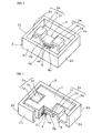
Fig. 2] Fig. 2 is a perspective view that illustrates a state in which a mass load member is placed in a piezoelectric generator according to the present invention. - [
Fig. 3] Fig. 3 is a partial cross-sectional perspective view for describing an internal structure of a piezoelectric generator according to an embodiment of the present invention. - [
Fig. 4] Fig. 4 is a perspective view of a piezoelectric generator according to an embodiment of the present invention seen from below. - [
Fig. 5] Fig. 5 is a perspective view for describing a structure of a mother prepared for obtaining a piezoelectric generator according to an embodiment of the present invention. - [
Fig. 6] Fig. 6 is a partial cut-away cross-sectional view that illustrates one example of a traditional piezoelectric generator. - The present invention is clarified below by describing concrete embodiments of the present invention with reference to the drawings.
-
Figs. 1(a) and (b) are a front cross-sectional view of a piezoelectric generator according to an embodiment of the present invention and a perspective view that illustrates an outer appearance thereof. - A
piezoelectric generator 1 includes asupport member 2 made of ceramic. Specifically, thesupport member 2 includes arectangular plate base 2a and a plurality ofside walls 2b to 2e upwardly extending from the outer edge of thebase 2a. - The
side wall 2b and theside wall 2d face each other, and theside wall 2c and theside wall 2e face each other. The length in a direction connecting theside walls side walls - A vibrating
plate 3 extending between theside walls plate 3 is made of ceramic and formed by firing integral with thesupport member 2. A first end of the vibratingplate 3 is coupled to an internal surface of theside wall 2b, and a second end thereof is coupled to theside wall 2d, which is opposite to theside wall 2b. - The dimension of the
support member 2 in its width direction, that is, the dimension in a direction connecting theside walls side walls Fig. 2 , the vibratingplate 3 is arranged in a central portion in a width direction in a space surrounded by theside walls 2b to 2e of thesupport member 2. - The vibrating
plate 3 includes first andsecond bends 3a and 3b. The first bend 3a includes afirst section 3d, asecond section 3e, and athird section 3f. Thefirst section 3d extends upwardly from the inner end of a horizontally extendingcoupling section 3c connected to the inner surface of theside wall 2b of thesupport member 2. Thesecond section 3e horizontally extends from the upper end of thefirst section 3d. Thethird section 3f downwardly extends from the inner end of thesecond section 3e. Similarly, thesecond bend 3b also includes afirst section 3d, asecond section 3e, and athird section 3f. A horizontally extending vibrating-platemain section 3g is arranged so as to link the lower end of thethird section 3f of the first bend 3a and the lower end of thethird section 3f of thesecond bend 3b. Apiezoelectric element 4 is bonded to the lower surface of the vibrating-platemain section 3g. - For the present invention, the piezoelectric element is placed on the vibrating plate and bonded thereto. Here, "bonded" also includes a structure in which they are integrated with each other by integral firing, as described above, and is not limited to a structure in which the piezoelectric element is fixed by the use of adhesive or bond.
- The vibrating-plate
main section 3g is a flat plate section, and its longitudinal direction is the same as the longitudinal direction of thesupport member 2, as illustrated inFig. 2 . - The first and
second bends 3a and 3b are symmetrically arranged such that thepiezoelectric element 4 is disposed therebetween. - The
piezoelectric element 4 includes a piezoelectric plate 4a as a piezoelectric ceramic body, afirst electrode 4b disposed on the upper surface of the piezoelectric plate 4a, and asecond electrode 4c disposed on the lower surface of the piezoelectric plate 4a. - For the present embodiment, the piezoelectric plate 4a is made of PZT piezoelectric ceramics. However, the piezoelectric plate 4a may be made of other piezoelectric ceramics.
- For the present embodiment, the first and
second electrodes support member 2 and the vibratingplate 3. - For the present embodiment, the piezoelectric plate 4a is subjected to polarization in its thickness direction.
- The direction of polarization of the piezoelectric plate 4a is not limited to its thickness direction, and it may be polarized in another direction.
- A
mass load member 6 is mounted on the upper surface of the vibrating-platemain section 3g such that abinder 5 is disposed therebetween. An appropriate binder, such as glass paste, can be used as thebinder 5. For the present embodiment, thebinder 5 and themass load member 6 are made of the same material, and they are coupled together by integral firing. - The
mass load member 6 can be made of any material as long as it can load mass to the vibrating-platemain section 3g. Preferably, the material may be metal or ceramic because it can load sufficient mass. For the present embodiment, themass load member 6 is made of the same ceramic as that of thebinder 5 and the vibratingplate 3. - The
mass load member 6 has a substantially H-shaped planar figure, as illustrated inFigs. 1(b) and 3 . That is, themass load member 6 is formed so as to have an area larger than the portion bound by thebinder 5. This enables larger mass to be loaded to the vibrating-platemain section 3g. - The
mass load member 6 has a substantially H-shaped form so as to occupy almost all regions, including the portion directly above the vibrating-platemain section 3g, other than the portion in which thebends 3a and 3b are disposed within an opening having the shape of a rectangular frame of thesupport member 2. That is, themass load member 6 is formed so as to be close to lateral portions of thebends 3a and 3b. The use of themass load member 6 having such a large area enables large mass to be loaded to the vibrating-platemain section 3g. - However, the planar figure of the
mass load member 6 is not limited to the above example. Themass load member 6 may be disposed only directly above the vibrating-platemain section 3g. Alternatively, themass load member 6 may be disposed only directly above the vibrating-platemain section 3g and on the both sides in its width direction. - The
piezoelectric generator 1 according to the present embodiment is fixed to a portion to which vibration or distortion is applied. This fixation is performed by fixing any portion of the outer surface of thesupport member 2 to an installation portion. When vibration, distortion, or acceleration is applied from the installation portion, the vibrating-platemain section 3g and thepiezoelectric element 4 supported by thebends 3a and 3b vibrate in the directions indicated by the arrows illustrated inFig. 1(a) . That is, they vibrate vertically inFig. 1(a) . Because themass load member 6 is mounted on the vibrating-platemain section 3g, larger amplitude is obtainable. Due to the above vibration, larger electric power is extracted from theelectrodes - Also, because the vibration body including the vibrating-plate
main section 3g and thepiezoelectric element 4 is supported at both ends, in addition, because it is supported employing the first andsecond bends 3a and 3b, it is not susceptible to the effects resulting from conditions of installation. That is, the effects resulting from the installation portion at which thesupport member 2 is fixed are reduced by thebends 3a and 3b, which are the above-described elastic support structure, the effects resulting from conditions of installation do not tend to reach the vibration portion. Therefore, variations in the resonant frequency in the vibration portion including the vibrating-platemain section 3g and thepiezoelectric element 4 caused by conditions of installation does not tend to occur. Accordingly, thepiezoelectric generator 1 exhibiting reduced variations in the power generation efficiency can be provided. - In particular, because the first and
second bends 3a and 3b are symmetrically arranged such that thepiezoelectric element 4 is positioned therebetween, the tendency for the resonance frequency to vary is further reduced. However, the first andsecond bends 3a and 3b may not be symmetrically arranged. - Next, one example method of manufacturing the above
piezoelectric generator 1 is described. - In manufacturing the above
piezoelectric generator 1, as previously described, the use of the integral firing technique can enhance the manufacturing efficiency and reduce the cost. More specifically, a mother structure in which a plurality ofsupport members 2, vibratingplates 3, andpiezoelectric elements 4 are included is obtained by the integral firing technique. After such a mother structure is obtained, themass load member 6 is bound in the rectangular opening of thesupport member 2 of each of thepiezoelectric elements 4 with the binder disposed therebetween, as illustrated in the perspective view ofFig. 5 . In this way, a motherpiezoelectric element assembly 11 illustrated inFig. 5 is obtainable. The mother structure is cut in its thickness direction such that the motherpiezoelectric element assembly 11 is divided into individualpiezoelectric elements 4. In this way, a plurality ofpiezoelectric generators 1 is obtainable by obtaining a mother structure in which a mother vibrating plate, a plurality of piezoelectric elements, and a plurality of support members are integrated with each other by the use of the integral firing technique and then cutting the structure in a downstream process. Therefore, the manufacturing efficiency can be improved, and the cost can be reduced. - The
support member 2, vibratingplate 3, andpiezoelectric element 4 are formed by the use of the integral firing technique. However, it is not necessary to use the same ceramic material in these components. That is, ceramic forming thesupport member 2, ceramic forming the vibratingplate 3, and ceramic forming the piezoelectric plate 4a of thepiezoelectric element 4 do not have to be the same. In response to required characteristics, an appropriate ceramic material may be preferably used. For example, it may be preferable that thesupport member 2 be made using ceramic having good mechanical strength and electrical insulation, such as Al2O3 or ZrO2. It may be preferable that the vibratingplate 3 be made using ceramic that has sufficient mechanical strength even when it is thin to some extent, can achieve an elastic support structure of thebends 3a and 3b, and has good toughness, for example, Al2O3 or ZrO2. - As the ceramic forming the piezoelectric plate 4a, aside from the previously described PZT piezoelectric ceramics, appropriate piezoelectric ceramics exhibiting good piezoelectricity may also preferably be used. The material of the above-described first and
second electrodes - However, it may be preferable that the vibrating
plate 3 and thesupport member 2 be made of the same ceramic material because both can be integrated more strongly by the use of the integral firing technique. - The present invention features supporting the vibrating-plate
main section 3g, to which thepiezoelectric element 4 is bonded, at both ends employing the first and second bends. Therefore, after being formed separately, the vibratingplate 3 and thepiezoelectric element 4 may be bonded together by the use of an appropriate bond. Similarly, as for thesupport member 2 and the vibratingplate 3, the vibratingplate 3 may be fixed by the use of an appropriate bond to thesupport member 2 formed in advance. - Accordingly, the
support member 2 and the vibratingplate 3 may also be made of a material other than ceramic. For example, thesupport member 2 may be made of a synthetic resin or metal, and the vibratingplate 3 may also be made of metal or a synthetic resin. -
- 1
- piezoelectric generator
- 2
- support member
- 2a
- base
- 2b-2e
- side walls
- 3
- vibrating plate
- 3a
- bend
- 3b
- bend
- 3c
- coupling section
- 3d
- first section
- 3e
- second section
- 3f
- third section
- 3g
- vibrating-plate main section
- 4
- piezoelectric element
- 4a
- piezoelectric plate
- 4b, 4c
- first and second electrodes
- 5
- binder
- 6
- mass load member
- 11
- piezoelectric element assembly
Claims (7)
- A piezoelectric generator comprising:a piezoelectric element including a piezoelectric ceramic body and first and second electrodes, the piezoelectric ceramic body having first and second surfaces facing each other, the first and second electrodes being disposed on the first and second surfaces of the piezoelectric ceramic body, respectively; anda vibrating plate on which the piezoelectric element is placed such that the first or second surface is adjacent thereto,wherein the vibrating plate includes a vibrating-plate main section on which the piezoelectric element is placed, a first bend disposed at one side of the vibrating-plate main section, and a second bend disposed at an opposite side thereof such that the piezoelectric element is positioned between the first and second bends, the piezoelectric generator further comprising a support member supporting the vibrating plate at a location outside the first and second bends of the vibrating plate, wherein a vibration portion including the piezoelectric element and the vibrating-plate main section is supported at both ends.
- The piezoelectric generator according to Claim 1,
wherein the first and second bends are symmetrical with respect to the piezoelectric element. - The piezoelectric generator according to Claim 1 or 2, wherein the vibrating plate is made of ceramic and formed by firing integral with the piezoelectric element.
- The piezoelectric generator according to Claim 3,
wherein the support member is made of ceramic and formed by firing integral with the vibrating plate. - The piezoelectric generator according to any one of Claims 1 to 4, further comprising a mass load member provided to the piezoelectric element.
- A method of manufacturing a piezoelectric generator according to any one of Claims 1 to 5, the method comprising the steps of:preparing a structure in which a plurality of piezoelectric elements and a plurality of support members are integral with a mother vibrating plate; andobtaining piezoelectric generators by cutting the structure.
- The method of manufacturing a piezoelectric generator according to Claim 6, wherein the structure in which the mother vibrating plate, the plurality of piezoelectric elements, and the plurality of support members are integral with each other is prepared by a ceramic integral firing technique.
Applications Claiming Priority (2)
| Application Number | Priority Date | Filing Date | Title |
|---|---|---|---|
| JP2008182576 | 2008-07-14 | ||
| PCT/JP2009/003067 WO2010007735A1 (en) | 2008-07-14 | 2009-07-02 | Piezoelectric power generation device |
Publications (3)
| Publication Number | Publication Date |
|---|---|
| EP2312740A1 true EP2312740A1 (en) | 2011-04-20 |
| EP2312740A4 EP2312740A4 (en) | 2013-05-01 |
| EP2312740B1 EP2312740B1 (en) | 2014-06-04 |
Family
ID=41550147
Family Applications (1)
| Application Number | Title | Priority Date | Filing Date |
|---|---|---|---|
| EP09797664.1A Active EP2312740B1 (en) | 2008-07-14 | 2009-07-02 | Piezoelectric power generation device |
Country Status (5)
| Country | Link |
|---|---|
| US (1) | US8058774B2 (en) |
| EP (1) | EP2312740B1 (en) |
| JP (1) | JP5136644B2 (en) |
| CN (1) | CN102124643B (en) |
| WO (1) | WO2010007735A1 (en) |
Families Citing this family (15)
| Publication number | Priority date | Publication date | Assignee | Title |
|---|---|---|---|---|
| JP2012044747A (en) * | 2010-08-17 | 2012-03-01 | Seiko Epson Corp | Electrostatic induction generation device |
| JP5720038B2 (en) * | 2010-11-29 | 2015-05-20 | 独立行政法人科学技術振興機構 | Hybrid power generation element |
| CN102594201A (en) * | 2012-02-17 | 2012-07-18 | 南京航空航天大学 | Vibration energy recovery device |
| US9445200B2 (en) * | 2012-05-14 | 2016-09-13 | Electronics And Telecommunications Research Institute | Piezoelectric speaker having weight and method of producing the same |
| KR101640446B1 (en) * | 2014-10-10 | 2016-07-18 | 주식회사 엠플러스 | Piezoelectric vibration actuator |
| CN104320018A (en) * | 2014-10-17 | 2015-01-28 | 上海交通大学 | Piezoelectric triboelectricity composite vibration energy harvester |
| JP5759641B1 (en) * | 2014-10-24 | 2015-08-05 | 太陽誘電株式会社 | Electroacoustic transducer and electronic device |
| JP6418898B2 (en) * | 2014-10-30 | 2018-11-07 | 京セラ株式会社 | Piezoelectric generator |
| WO2017057031A1 (en) * | 2015-09-29 | 2017-04-06 | ヤマハ株式会社 | Vibrating structure |
| TWM547213U (en) * | 2017-05-19 | 2017-08-11 | Topray Mems Inc | Linear vibration actuator having plate-spring type suspension system |
| EP3460981B1 (en) * | 2017-07-26 | 2022-03-30 | Tri-Force Management Corporation | Power generation element |
| CN108712105B (en) * | 2018-05-08 | 2020-08-11 | 湘潭大学 | Piezoelectric energy harvester for bicycle |
| JP7136318B2 (en) * | 2019-02-22 | 2022-09-13 | 株式会社村田製作所 | Vibration device and its manufacturing method |
| CN112217418B (en) * | 2020-09-01 | 2022-03-25 | 长安大学 | Assembled road piezoelectric power generation system and paving method |
| JP7847560B2 (en) * | 2023-04-04 | 2026-04-17 | 株式会社鷺宮製作所 | Resonators and vibration power generation devices utilizing resonators |
Family Cites Families (38)
| Publication number | Priority date | Publication date | Assignee | Title |
|---|---|---|---|---|
| NL6813993A (en) * | 1968-09-30 | 1970-04-01 | ||
| US3707131A (en) * | 1970-10-19 | 1972-12-26 | Dynamics Corp Massa Div | Electroacoustic transducers of the bilaminar flexural vibrating type |
| US3786202A (en) * | 1972-04-10 | 1974-01-15 | Motorola Inc | Acoustic transducer including piezoelectric driving element |
| CA1090441A (en) * | 1976-11-10 | 1980-11-25 | Toshibumi Kamiyama | Frost detector |
| JPS5753798U (en) * | 1980-09-11 | 1982-03-29 | ||
| US4430529A (en) * | 1980-12-24 | 1984-02-07 | Murata Manufacturing Co., Ltd. | Piezoelectric loudspeaker |
| US4414436A (en) * | 1982-04-19 | 1983-11-08 | Pioneer Speaker Components, Inc. | Narrow-frequency band acoustic transducer |
| US4475014A (en) * | 1982-09-13 | 1984-10-02 | Harman-Motive Inc. | Acoustical transducer |
| US4461930A (en) * | 1982-09-23 | 1984-07-24 | Pioneer Speaker Components, Inc. | Acoustic transducer with honeycomb diaphragm |
| DE3407980A1 (en) * | 1983-04-20 | 1984-10-25 | Tadashi Tokio/Tokyo Sawafuji | CRYSTAL SOUND GENERATOR |
| US4554414A (en) * | 1983-04-28 | 1985-11-19 | Harman International Industries Incorporated | Multi-driver loudspeaker |
| JPS60190100A (en) * | 1984-03-09 | 1985-09-27 | Murata Mfg Co Ltd | Piezoelectric speaker |
| JPH0749914Y2 (en) * | 1986-01-29 | 1995-11-13 | 株式会社村田製作所 | Ultrasonic transducer |
| JP2605355B2 (en) * | 1988-06-14 | 1997-04-30 | 日本電気株式会社 | Driving method of ultrasonic motor and vibrator for ultrasonic motor |
| JPH0274868A (en) * | 1988-09-09 | 1990-03-14 | Nissan Motor Co Ltd | Piezoelectric type dynamic quantity sensor |
| JPH06261565A (en) * | 1993-03-09 | 1994-09-16 | Ricoh Co Ltd | Vibrating actuator |
| JPH07107752A (en) | 1993-09-30 | 1995-04-21 | Mitsuteru Kimura | Piezoelectric generating device |
| JP3418840B2 (en) * | 1993-12-01 | 2003-06-23 | 日本特殊陶業株式会社 | Silent vibration alarm |
| US5962952A (en) * | 1995-11-03 | 1999-10-05 | Coherent Technologies, Inc. | Ultrasonic transducer |
| JPH09225401A (en) * | 1996-02-22 | 1997-09-02 | Fukoku Co Ltd | Vibration device for notification |
| JP3970360B2 (en) * | 1996-10-22 | 2007-09-05 | 北陸電気工業株式会社 | Piezoelectric sounder |
| JPH10192782A (en) * | 1996-12-27 | 1998-07-28 | Ceratec:Kk | Receiving vibrator and portable receiver with receiving vibrator |
| JP2000233157A (en) * | 1999-02-15 | 2000-08-29 | Murata Mfg Co Ltd | Vibration generator |
| US6252336B1 (en) * | 1999-11-08 | 2001-06-26 | Cts Corporation | Combined piezoelectric silent alarm/battery charger |
| JP4474718B2 (en) * | 2000-02-17 | 2010-06-09 | 株式会社村田製作所 | Piezoelectric wind power generator |
| JP2002159917A (en) * | 2000-11-22 | 2002-06-04 | Terumo Kogyo:Kk | Vibration generator |
| JP4793893B2 (en) * | 2001-02-23 | 2011-10-12 | Necトーキン株式会社 | Piezoelectric generator unit |
| JP2003189641A (en) * | 2001-12-12 | 2003-07-04 | Nec Tokin Corp | Power generator |
| CN100477515C (en) * | 2004-10-14 | 2009-04-08 | 株式会社村田制作所 | Energy confinement piezo-resonator |
| WO2006046938A1 (en) * | 2004-10-21 | 2006-05-04 | Societe De Technologie Michelin | A miniaturized piezoelectric based vibrational energy harvester |
| JP2007150037A (en) * | 2005-11-29 | 2007-06-14 | Kyocera Corp | Lead-containing piezoelectric body, piezoelectric actuator, and liquid ejection device |
| JP4991145B2 (en) * | 2005-11-30 | 2012-08-01 | ブラザー工業株式会社 | Inspection method of piezoelectric actuator |
| JP2007166881A (en) * | 2005-12-19 | 2007-06-28 | Taiheiyo Cement Corp | Electric power generating apparatus |
| JP3939737B1 (en) * | 2006-04-03 | 2007-07-04 | 太平洋セメント株式会社 | Power generator |
| US7692363B2 (en) * | 2006-10-02 | 2010-04-06 | Image Acoustics, Inc. | Mass loaded dipole transduction apparatus |
| JP4965973B2 (en) * | 2006-11-08 | 2012-07-04 | キヤノン株式会社 | Vibration type actuator |
| JP2009017735A (en) * | 2007-07-06 | 2009-01-22 | Olympus Corp | Ultrasonic motor |
| WO2009141970A1 (en) * | 2008-05-19 | 2009-11-26 | 株式会社村田製作所 | Vibrating device |
-
2009
- 2009-07-02 WO PCT/JP2009/003067 patent/WO2010007735A1/en not_active Ceased
- 2009-07-02 JP JP2010520748A patent/JP5136644B2/en active Active
- 2009-07-02 CN CN200980126838.2A patent/CN102124643B/en active Active
- 2009-07-02 EP EP09797664.1A patent/EP2312740B1/en active Active
-
2011
- 2011-01-11 US US13/004,137 patent/US8058774B2/en active Active
Also Published As
| Publication number | Publication date |
|---|---|
| US8058774B2 (en) | 2011-11-15 |
| US20110121685A1 (en) | 2011-05-26 |
| CN102124643A (en) | 2011-07-13 |
| CN102124643B (en) | 2014-04-02 |
| EP2312740A4 (en) | 2013-05-01 |
| JP5136644B2 (en) | 2013-02-06 |
| WO2010007735A1 (en) | 2010-01-21 |
| EP2312740B1 (en) | 2014-06-04 |
| JPWO2010007735A1 (en) | 2012-01-05 |
Similar Documents
| Publication | Publication Date | Title |
|---|---|---|
| EP2312740B1 (en) | Piezoelectric power generation device | |
| CN101771395B (en) | Flexural vibration element and electronic component | |
| US9662680B2 (en) | Ultrasonic transducer | |
| JP4767369B1 (en) | Piezoelectric power generation element and power generation method using piezoelectric power generation element | |
| US20150145376A1 (en) | Energy harvesting device and method for forming the same | |
| JP5237705B2 (en) | Power generation device | |
| CN103238271B (en) | Piezoelectric generating device and manufacture method thereof | |
| EP1796256A1 (en) | Piezoelectric device and piezoelectric switch employing same | |
| US9135906B2 (en) | Ultrasonic generator | |
| JPH036720B2 (en) | ||
| EP2566039A1 (en) | Vibration power generation device | |
| JP5549164B2 (en) | Piezoelectric generator | |
| WO2012073741A1 (en) | Piezoelectric power generating device | |
| CN106100435B (en) | Piezo Motor | |
| CN107395063A (en) | Energy collecting device | |
| CN104011889A (en) | Piezoelectric energy harvesting device or actuator | |
| US7631558B2 (en) | Microsystem, more particularly microgyrometer, with capacitive electrode detection element | |
| JPWO2020170937A1 (en) | Vibration device and its manufacturing method | |
| JP6418898B2 (en) | Piezoelectric generator | |
| JP2013146143A (en) | Vibration force power generating apparatus | |
| JP5614629B2 (en) | Power supply | |
| CN118611617A (en) | A MEMS piezoelectric resonator | |
| JP2006324893A (en) | Piezoelectric type oscillating element | |
| JP5270622B2 (en) | Piezoelectric acceleration sensor | |
| JP2023111184A (en) | Vibration element, vibration device, and method for manufacturing vibration device |
Legal Events
| Date | Code | Title | Description |
|---|---|---|---|
| PUAI | Public reference made under article 153(3) epc to a published international application that has entered the european phase |
Free format text: ORIGINAL CODE: 0009012 |
|
| 17P | Request for examination filed |
Effective date: 20110209 |
|
| AK | Designated contracting states |
Kind code of ref document: A1 Designated state(s): AT BE BG CH CY CZ DE DK EE ES FI FR GB GR HR HU IE IS IT LI LT LU LV MC MK MT NL NO PL PT RO SE SI SK SM TR |
|
| AX | Request for extension of the european patent |
Extension state: AL BA RS |
|
| DAX | Request for extension of the european patent (deleted) | ||
| A4 | Supplementary search report drawn up and despatched |
Effective date: 20130404 |
|
| RIC1 | Information provided on ipc code assigned before grant |
Ipc: H01L 41/39 20130101ALI20130327BHEP Ipc: H02N 2/18 20060101AFI20130327BHEP Ipc: H01L 41/113 20060101ALI20130327BHEP |
|
| REG | Reference to a national code |
Ref country code: DE Ref legal event code: R079 Ref document number: 602009024500 Country of ref document: DE Free format text: PREVIOUS MAIN CLASS: H02N0002000000 Ipc: H02N0002180000 |
|
| RIC1 | Information provided on ipc code assigned before grant |
Ipc: H01L 41/39 20130101ALI20131122BHEP Ipc: H01L 41/113 20060101ALI20131122BHEP Ipc: H02N 2/18 20060101AFI20131122BHEP |
|
| GRAP | Despatch of communication of intention to grant a patent |
Free format text: ORIGINAL CODE: EPIDOSNIGR1 |
|
| INTG | Intention to grant announced |
Effective date: 20140103 |
|
| GRAS | Grant fee paid |
Free format text: ORIGINAL CODE: EPIDOSNIGR3 |
|
| GRAA | (expected) grant |
Free format text: ORIGINAL CODE: 0009210 |
|
| AK | Designated contracting states |
Kind code of ref document: B1 Designated state(s): AT BE BG CH CY CZ DE DK EE ES FI FR GB GR HR HU IE IS IT LI LT LU LV MC MK MT NL NO PL PT RO SE SI SK SM TR |
|
| REG | Reference to a national code |
Ref country code: GB Ref legal event code: FG4D |
|
| REG | Reference to a national code |
Ref country code: CH Ref legal event code: EP |
|
| REG | Reference to a national code |
Ref country code: AT Ref legal event code: REF Ref document number: 671577 Country of ref document: AT Kind code of ref document: T Effective date: 20140615 |
|
| REG | Reference to a national code |
Ref country code: IE Ref legal event code: FG4D |
|
| REG | Reference to a national code |
Ref country code: DE Ref legal event code: R096 Ref document number: 602009024500 Country of ref document: DE Effective date: 20140717 |
|
| REG | Reference to a national code |
Ref country code: AT Ref legal event code: MK05 Ref document number: 671577 Country of ref document: AT Kind code of ref document: T Effective date: 20140604 |
|
| REG | Reference to a national code |
Ref country code: NL Ref legal event code: VDEP Effective date: 20140604 |
|
| PG25 | Lapsed in a contracting state [announced via postgrant information from national office to epo] |
Ref country code: GR Free format text: LAPSE BECAUSE OF FAILURE TO SUBMIT A TRANSLATION OF THE DESCRIPTION OR TO PAY THE FEE WITHIN THE PRESCRIBED TIME-LIMIT Effective date: 20140905 Ref country code: CY Free format text: LAPSE BECAUSE OF FAILURE TO SUBMIT A TRANSLATION OF THE DESCRIPTION OR TO PAY THE FEE WITHIN THE PRESCRIBED TIME-LIMIT Effective date: 20140604 Ref country code: FI Free format text: LAPSE BECAUSE OF FAILURE TO SUBMIT A TRANSLATION OF THE DESCRIPTION OR TO PAY THE FEE WITHIN THE PRESCRIBED TIME-LIMIT Effective date: 20140604 Ref country code: LT Free format text: LAPSE BECAUSE OF FAILURE TO SUBMIT A TRANSLATION OF THE DESCRIPTION OR TO PAY THE FEE WITHIN THE PRESCRIBED TIME-LIMIT Effective date: 20140604 Ref country code: NO Free format text: LAPSE BECAUSE OF FAILURE TO SUBMIT A TRANSLATION OF THE DESCRIPTION OR TO PAY THE FEE WITHIN THE PRESCRIBED TIME-LIMIT Effective date: 20140904 |
|
| REG | Reference to a national code |
Ref country code: LT Ref legal event code: MG4D |
|
| PG25 | Lapsed in a contracting state [announced via postgrant information from national office to epo] |
Ref country code: SE Free format text: LAPSE BECAUSE OF FAILURE TO SUBMIT A TRANSLATION OF THE DESCRIPTION OR TO PAY THE FEE WITHIN THE PRESCRIBED TIME-LIMIT Effective date: 20140604 Ref country code: LV Free format text: LAPSE BECAUSE OF FAILURE TO SUBMIT A TRANSLATION OF THE DESCRIPTION OR TO PAY THE FEE WITHIN THE PRESCRIBED TIME-LIMIT Effective date: 20140604 Ref country code: HR Free format text: LAPSE BECAUSE OF FAILURE TO SUBMIT A TRANSLATION OF THE DESCRIPTION OR TO PAY THE FEE WITHIN THE PRESCRIBED TIME-LIMIT Effective date: 20140604 Ref country code: AT Free format text: LAPSE BECAUSE OF FAILURE TO SUBMIT A TRANSLATION OF THE DESCRIPTION OR TO PAY THE FEE WITHIN THE PRESCRIBED TIME-LIMIT Effective date: 20140604 |
|
| PG25 | Lapsed in a contracting state [announced via postgrant information from national office to epo] |
Ref country code: SK Free format text: LAPSE BECAUSE OF FAILURE TO SUBMIT A TRANSLATION OF THE DESCRIPTION OR TO PAY THE FEE WITHIN THE PRESCRIBED TIME-LIMIT Effective date: 20140604 Ref country code: EE Free format text: LAPSE BECAUSE OF FAILURE TO SUBMIT A TRANSLATION OF THE DESCRIPTION OR TO PAY THE FEE WITHIN THE PRESCRIBED TIME-LIMIT Effective date: 20140604 Ref country code: RO Free format text: LAPSE BECAUSE OF FAILURE TO SUBMIT A TRANSLATION OF THE DESCRIPTION OR TO PAY THE FEE WITHIN THE PRESCRIBED TIME-LIMIT Effective date: 20140604 Ref country code: ES Free format text: LAPSE BECAUSE OF FAILURE TO SUBMIT A TRANSLATION OF THE DESCRIPTION OR TO PAY THE FEE WITHIN THE PRESCRIBED TIME-LIMIT Effective date: 20140604 Ref country code: CZ Free format text: LAPSE BECAUSE OF FAILURE TO SUBMIT A TRANSLATION OF THE DESCRIPTION OR TO PAY THE FEE WITHIN THE PRESCRIBED TIME-LIMIT Effective date: 20140604 Ref country code: PT Free format text: LAPSE BECAUSE OF FAILURE TO SUBMIT A TRANSLATION OF THE DESCRIPTION OR TO PAY THE FEE WITHIN THE PRESCRIBED TIME-LIMIT Effective date: 20141006 |
|
| PG25 | Lapsed in a contracting state [announced via postgrant information from national office to epo] |
Ref country code: IS Free format text: LAPSE BECAUSE OF FAILURE TO SUBMIT A TRANSLATION OF THE DESCRIPTION OR TO PAY THE FEE WITHIN THE PRESCRIBED TIME-LIMIT Effective date: 20141004 Ref country code: NL Free format text: LAPSE BECAUSE OF FAILURE TO SUBMIT A TRANSLATION OF THE DESCRIPTION OR TO PAY THE FEE WITHIN THE PRESCRIBED TIME-LIMIT Effective date: 20140604 Ref country code: PL Free format text: LAPSE BECAUSE OF FAILURE TO SUBMIT A TRANSLATION OF THE DESCRIPTION OR TO PAY THE FEE WITHIN THE PRESCRIBED TIME-LIMIT Effective date: 20140604 |
|
| REG | Reference to a national code |
Ref country code: CH Ref legal event code: PL |
|
| REG | Reference to a national code |
Ref country code: DE Ref legal event code: R097 Ref document number: 602009024500 Country of ref document: DE |
|
| PG25 | Lapsed in a contracting state [announced via postgrant information from national office to epo] |
Ref country code: MC Free format text: LAPSE BECAUSE OF FAILURE TO SUBMIT A TRANSLATION OF THE DESCRIPTION OR TO PAY THE FEE WITHIN THE PRESCRIBED TIME-LIMIT Effective date: 20140604 |
|
| PLBE | No opposition filed within time limit |
Free format text: ORIGINAL CODE: 0009261 |
|
| STAA | Information on the status of an ep patent application or granted ep patent |
Free format text: STATUS: NO OPPOSITION FILED WITHIN TIME LIMIT |
|
| REG | Reference to a national code |
Ref country code: IE Ref legal event code: MM4A |
|
| REG | Reference to a national code |
Ref country code: FR Ref legal event code: ST Effective date: 20150331 |
|
| PG25 | Lapsed in a contracting state [announced via postgrant information from national office to epo] |
Ref country code: DK Free format text: LAPSE BECAUSE OF FAILURE TO SUBMIT A TRANSLATION OF THE DESCRIPTION OR TO PAY THE FEE WITHIN THE PRESCRIBED TIME-LIMIT Effective date: 20140604 Ref country code: CH Free format text: LAPSE BECAUSE OF NON-PAYMENT OF DUE FEES Effective date: 20140731 Ref country code: IT Free format text: LAPSE BECAUSE OF FAILURE TO SUBMIT A TRANSLATION OF THE DESCRIPTION OR TO PAY THE FEE WITHIN THE PRESCRIBED TIME-LIMIT Effective date: 20140604 Ref country code: LI Free format text: LAPSE BECAUSE OF NON-PAYMENT OF DUE FEES Effective date: 20140731 |
|
| 26N | No opposition filed |
Effective date: 20150305 |
|
| GBPC | Gb: european patent ceased through non-payment of renewal fee |
Effective date: 20140904 |
|
| PG25 | Lapsed in a contracting state [announced via postgrant information from national office to epo] |
Ref country code: FR Free format text: LAPSE BECAUSE OF NON-PAYMENT OF DUE FEES Effective date: 20140804 |
|
| REG | Reference to a national code |
Ref country code: DE Ref legal event code: R097 Ref document number: 602009024500 Country of ref document: DE Effective date: 20150305 |
|
| PG25 | Lapsed in a contracting state [announced via postgrant information from national office to epo] |
Ref country code: BE Free format text: LAPSE BECAUSE OF FAILURE TO SUBMIT A TRANSLATION OF THE DESCRIPTION OR TO PAY THE FEE WITHIN THE PRESCRIBED TIME-LIMIT Effective date: 20140604 |
|
| PG25 | Lapsed in a contracting state [announced via postgrant information from national office to epo] |
Ref country code: SI Free format text: LAPSE BECAUSE OF FAILURE TO SUBMIT A TRANSLATION OF THE DESCRIPTION OR TO PAY THE FEE WITHIN THE PRESCRIBED TIME-LIMIT Effective date: 20140604 Ref country code: GB Free format text: LAPSE BECAUSE OF NON-PAYMENT OF DUE FEES Effective date: 20140904 |
|
| PG25 | Lapsed in a contracting state [announced via postgrant information from national office to epo] |
Ref country code: IE Free format text: LAPSE BECAUSE OF NON-PAYMENT OF DUE FEES Effective date: 20140702 |
|
| PG25 | Lapsed in a contracting state [announced via postgrant information from national office to epo] |
Ref country code: SM Free format text: LAPSE BECAUSE OF FAILURE TO SUBMIT A TRANSLATION OF THE DESCRIPTION OR TO PAY THE FEE WITHIN THE PRESCRIBED TIME-LIMIT Effective date: 20140604 |
|
| PG25 | Lapsed in a contracting state [announced via postgrant information from national office to epo] |
Ref country code: MT Free format text: LAPSE BECAUSE OF FAILURE TO SUBMIT A TRANSLATION OF THE DESCRIPTION OR TO PAY THE FEE WITHIN THE PRESCRIBED TIME-LIMIT Effective date: 20140604 Ref country code: BG Free format text: LAPSE BECAUSE OF FAILURE TO SUBMIT A TRANSLATION OF THE DESCRIPTION OR TO PAY THE FEE WITHIN THE PRESCRIBED TIME-LIMIT Effective date: 20140604 |
|
| PG25 | Lapsed in a contracting state [announced via postgrant information from national office to epo] |
Ref country code: TR Free format text: LAPSE BECAUSE OF FAILURE TO SUBMIT A TRANSLATION OF THE DESCRIPTION OR TO PAY THE FEE WITHIN THE PRESCRIBED TIME-LIMIT Effective date: 20140604 Ref country code: HU Free format text: LAPSE BECAUSE OF FAILURE TO SUBMIT A TRANSLATION OF THE DESCRIPTION OR TO PAY THE FEE WITHIN THE PRESCRIBED TIME-LIMIT; INVALID AB INITIO Effective date: 20090702 Ref country code: LU Free format text: LAPSE BECAUSE OF NON-PAYMENT OF DUE FEES Effective date: 20140702 |
|
| PG25 | Lapsed in a contracting state [announced via postgrant information from national office to epo] |
Ref country code: MK Free format text: LAPSE BECAUSE OF FAILURE TO SUBMIT A TRANSLATION OF THE DESCRIPTION OR TO PAY THE FEE WITHIN THE PRESCRIBED TIME-LIMIT Effective date: 20140604 |
|
| PGFP | Annual fee paid to national office [announced via postgrant information from national office to epo] |
Ref country code: DE Payment date: 20250722 Year of fee payment: 17 |