EP2312711A2 - Terminal box - Google Patents
Terminal box Download PDFInfo
- Publication number
- EP2312711A2 EP2312711A2 EP10013259A EP10013259A EP2312711A2 EP 2312711 A2 EP2312711 A2 EP 2312711A2 EP 10013259 A EP10013259 A EP 10013259A EP 10013259 A EP10013259 A EP 10013259A EP 2312711 A2 EP2312711 A2 EP 2312711A2
- Authority
- EP
- European Patent Office
- Prior art keywords
- projecting piece
- engaging
- box casing
- engaged
- lid
- Prior art date
- Legal status (The legal status is an assumption and is not a legal conclusion. Google has not performed a legal analysis and makes no representation as to the accuracy of the status listed.)
- Granted
Links
Images


Classifications
-
- H—ELECTRICITY
- H02—GENERATION; CONVERSION OR DISTRIBUTION OF ELECTRIC POWER
- H02G—INSTALLATION OF ELECTRIC CABLES OR LINES, OR OF COMBINED OPTICAL AND ELECTRIC CABLES OR LINES
- H02G3/00—Installations of electric cables or lines or protective tubing therefor in or on buildings, equivalent structures or vehicles
- H02G3/02—Details
- H02G3/08—Distribution boxes; Connection or junction boxes
- H02G3/081—Bases, casings or covers
-
- H—ELECTRICITY
- H02—GENERATION; CONVERSION OR DISTRIBUTION OF ELECTRIC POWER
- H02G—INSTALLATION OF ELECTRIC CABLES OR LINES, OR OF COMBINED OPTICAL AND ELECTRIC CABLES OR LINES
- H02G3/00—Installations of electric cables or lines or protective tubing therefor in or on buildings, equivalent structures or vehicles
- H02G3/02—Details
- H02G3/06—Joints for connecting lengths of protective tubing or channels, to each other or to casings, e.g. to distribution boxes; Ensuring electrical continuity in the joint
- H02G3/0616—Joints for connecting tubing to casing
- H02G3/0625—Joints for connecting tubing to casing with means for preventing disengagement of conductors
- H02G3/0675—Joints for connecting tubing to casing with means for preventing disengagement of conductors with bolts operating in a direction parallel to the conductors
-
- H—ELECTRICITY
- H02—GENERATION; CONVERSION OR DISTRIBUTION OF ELECTRIC POWER
- H02G—INSTALLATION OF ELECTRIC CABLES OR LINES, OR OF COMBINED OPTICAL AND ELECTRIC CABLES OR LINES
- H02G3/00—Installations of electric cables or lines or protective tubing therefor in or on buildings, equivalent structures or vehicles
- H02G3/02—Details
- H02G3/08—Distribution boxes; Connection or junction boxes
- H02G3/14—Fastening of cover or lid to box
-
- H—ELECTRICITY
- H02—GENERATION; CONVERSION OR DISTRIBUTION OF ELECTRIC POWER
- H02G—INSTALLATION OF ELECTRIC CABLES OR LINES, OR OF COMBINED OPTICAL AND ELECTRIC CABLES OR LINES
- H02G3/00—Installations of electric cables or lines or protective tubing therefor in or on buildings, equivalent structures or vehicles
- H02G3/02—Details
- H02G3/08—Distribution boxes; Connection or junction boxes
- H02G3/16—Distribution boxes; Connection or junction boxes structurally associated with support for line-connecting terminals within the box
Definitions
- the present invention relates to a terminal box comprising: a box casing including terminal elements incorporated into the interior thereof; a lid element for closing an opening of the box casing; and an engaging mechanism for fixedly engaging an engaging element provided in the lid element with an engaged element provided in the box casing by pressing the lid element against the box casing.
- terminal box for a solar cell module disclosed in Japanese Patent No. 3014628 .
- This terminal box comprises an engaging element provided in a lid member including a projecting piece extending in a direction of pressing the lid member, and an engaging opening formed in the projecting piece.
- an engaged element is provided in a box casing and includes a convex surface projecting from an outer surface of the box casing to allow the engaged element to fit into the engaging opening.
- the lid member In fixedly engaging the engaging element with the engaged element in order to fix the lid member to the box casing, the lid member is pressed against the box casing to move the projecting piece with the projecting piece being elastically deformed so that a distal end portion of the projecting piece rides on the convex surface. Then, the projecting piece is restorably deformed as the distal end portion of the projecting piece is disengaged from the convex surface, thereby allowing the convex surface to fit into the engaging opening.
- the projecting piece is plastically deformed.
- the lid member removed from the box casing is not reusable.
- the present invention has been made having regard to the above-noted drawbacks, and its object is to provide a terminal box capable of simplifying the operations of removing the lid member from the box casing.
- the engaging element includes the projecting piece extending in the pressing direction of the lid member, and the engaging pawl extending in the direction vertical to the extending direction of the projecting piece and provided in part of the projecting piece other than the distal end portion of the projecting piece, while the engaged element has the receiving hole opening toward the outer side of the box casing and allowing the distal end portion of the projecting piece to be exposed to the outside when engaged with the engaging pawl.
- the terminal box with this arrangement allows the distal end portion of the projecting piece to be pressed toward the disengagement side and moved toward the direction opposite from the pressing direction of the lid member with the control member inserted into the receiving hole from the outer side of the box casing. More particularly, the operation of disengaging the engaging element from the engaged element and the operation of moving the lid member in the direction opposite from its pressing direction can be performed with continuous operations using a single control member. This simplifies the operations for removing the lid member from the box casing.
- a second characteristic feature of the present invention lies in that the projecting piece has a bottom surface at the distal end portion thereof opposed to a wall surface portion of an inner wall surface of the receiving hole positioned adjacent a downward side of the projecting piece in the pressing direction.
- a flat control member is inserted between the wall surface portion of the receiving hole positioned adjacent the downward side of the projection piece in the pressing direction and the bottom surface provided in the distal end portion of the projecting piece to press the distal end portion of the projecting piece toward the disengagement side. Then, the flat control member is rotated with the wall surface being served as a reaction force receiver, thereby moving the projecting piece in the direction opposite from the direction of pressing the lid element.
- a third characteristic feature of the present invention lies in that the terminal box further comprises a restricting portion for restricting displacement of the projecting piece to a predetermined position when the engaging pawl or the distal end portion of the projecting piece is depressed through the receiving hole in disengaging the engaging pawl from the receiving hole.
- the lid member removed from the box casing is adequately reusable.
- the restricting portion is provided in the box casing.
- the fourth characteristic feature of the present invention lies in that the engaging pawl has a projecting height smaller than a depth-wise width of an inner wall surface of the receiving hole.
- the engaging pawl does not project outward of the inner wall surface of the receiving hole. Thus, it is prevented that the engaging pawl is caught by any other element and inadvertently disengaged from the receiving hole.
- Figs. 1 and 2 show a terminal box for a solar cell module in accordance with the present invention.
- the terminal box comprises a box casing 2 made of resin including a pair of metal terminal elements 1 (see Fig. 3 ) incorporated into the interior of the casing, a lid element 4 made of resin for closing an opening 3 of the box casing 2, and an engaging mechanism 7 for fixedly engaging an engaging element 5 provided in the lid element 4 with an engaged element 6 provided in the box casing 2 by pressing the lid element 4 against the box casing 2.
- the box casing 2 receives a pair of output cables 8 connected to a capacitor, for example, and connects them to the terminal elements 1, respectively.
- an input cable inlet 9 for receiving a pair of input cables (not shown) connected to the solar cell module so that the input cables are connected to the terminal elements 1, respectively.
- the terminal elements 1 are fixed through terminal fixing clicks 10 integrally formed with an inner bottom portion of the box casing 2.
- the terminal elements 1 are connected to each other through a reverse-current short-circuit diode 11.
- the output cables 8 are inserted into tubular members 12 integrally formed with the box casing 2 and connected to the terminal elements 1.
- a gap between each tubular member 12 and each output cable 8 is closed by a cable packing 13 attached to an inner side of the tubular member 12 to prevent entry of water.
- the cable packing 13 is fastened to the output cables 8 through a cap 14 screwed to the tubular member 12.
- the lid element 4 has a fitting tubular element 16 integrally formed with an inner side thereof and being fitted into an inner periphery 15 of the opening of the box casing 2.
- a rubber O-ring 17 acting as a waterproof seal element is fitted into a circumferential groove formed in an outer periphery of the fitting tubular element 16 at an interface between the outer periphery of the fitting tubular element 16 and the opening inner periphery 15.
- the lid element 4 has a plurality of vents 18 formed therein. As shown in Fig. 5 , a waterproof sheet 19 for covering the vents 18 is affixed to an inner surface of the lid element 4 through an adhesive to prevent water from entering from the vents 18.
- the engaging mechanism 7 includes a pair of the engaging elements 5 made of resin, and integrally formed with and symmetrically provided in an outer peripheral portion of the lid element 4 to oppose with each other, and a pair of engaged elements 6 made of resin, and integrally formed with and symmetrically provided in an outer peripheral portion of the box casing 2 to oppose with each other.
- Each of the engaging elements 5 has a plate-like projecting piece 21 extending in a pressing direction of the lid element 4 along an extension 20 extending from a side edge portion of the lid element 4, and an engaging pawl 23 extending in a direction vertical to the extending direction of the projecting piece 21 and provided in part of the projecting piece 21 other than a distal end portion 22 of the projecting piece 21.
- Each of the engaged elements 6 has a receiving hole 24 that opens toward an outer side of the box casing 2 and allows the distal end portion 22 of the projecting piece 21 to be exposed to the outside when engaged with the engaging pawl 23.
- each engaged element 6 has a pair of vertical ribs 25 extending along the pressing direction, a connecting rib 26 provided in an outer surface of the box casing 2 for connecting the pair of vertical ribs 25 at distal end portions thereof in the pressing direction, and an intermediate plate-like beam element 27 spaced apart from the outer surface of the box casing 2 for connecting of the vertical ribs 25 at intermediate portions thereof.
- the above arrangement provides an inserting hole 28, to which the projecting piece 21 is inserted until the engaging pawl 23 comes out of the insert hole.
- the inserting hole 28 is formed between the intermediate plate-like beam element 27 and the outer surface of the box casing 2 to form the receiving hole 24 surrounded by the pair of vertical ribs 25, connecting rib 26 and intermediate plate-like beam element 27.
- the engaging pawl 23 coming out of the inserting hole 28 is engageable with the intermediate plate-like beam element 27.
- a projecting height H (see Fig. 6(a) ) of the engaging pawl 23 from the projecting piece 21 is smaller than a depth D (see Fig. 6(b) ) of an inner wall portion of an inner wall surface of the receiving hole 24 formed by the intermediate plate-like beam element 27 engaged with the engaging pawl 23.
- This arrangement prevents a distal end of the engaging pawl 23 engaged with the intermediate plate-like beam element 27 from projecting outward of the intermediate plate-like beam element 27.
- a gap between the distal ends of the engaging pawls 23 in the opposite engaging elements 5 is larger than a gap between the intermediate plate-like beam elements 27 in the opposite engaged elements 6. This allows the respective projecting pieces 21 to be inserted into the receiving holes 28 together with the engaging pawls 23 by being elastically deformed toward the box casing 2.
- the distal end portion 22 of the projecting piece 21 has a wall surface positioned adjacent a downward side of the inner wall surface of the receiving hole 24 in the direction of pressing the projecting piece 21.
- the wall surface acts as a bottom surface 29 opposed to a top surface of the connecting rib 26 (see Fig. 6 ) and is formed by the thickness of the distal end portion 22 of the projecting piece 21 that has a thickness smaller than the thickness of the top surface of the engaging pawl 23 of the projecting piece 21 measured from the outer surface of the lid element 4.
- a restricting portion 30 is provided in the box casing 2 for restricting an amount of displacement of the projecting piece 21 within an elastic range when the engaging pawl 23 or the distal end portion 22 of the projecting piece 21 is depressed through the receiving hole 24 in disengaging the engaging pawl 23 from the receiving hole 24.
- the restricting portion 30 is formed by an outer surface portion of the box casing 2 facing the receiving hole 24.
- a contacting surface 31 (see Fig. 6 ) that inclines closer to the projecting piece 21 adjacent the forward portion thereof in the inserting direction.
- the intermediate plate-like beam element 27 has a guide surface 32 (see Fig. 6 ), to which the contacting surface 31 is pressed.
- the guide surface 32 inclines closer to the box casing 2 adjacent the forward portion thereof in the inserting direction (adjacent the bottom of the box casing 2).
- the lid element 4 having the O-ring 17 attached to the circumferential groove of the fitting tubular element 16 is pressed against the box casing 2 with the lid element 4 being faced with the box casing 2 so that the opposite projecting pieces 21 face the opposite receiving holes 28, respectively.
- each projecting piece 21 is restorably deformed and each engaging pawl 23 is fixedly engaged with a corner of the intermediate plate-like beam element 27 at the forward portion thereof in the pressing direction. This allows the lid element 4 to be rigidly fixedly engaged with the box casing 2.
- a flat distal end of a control rod (control element) 33 is inserted between the bottom surface 29 of the projecting piece 21 and the top surface of the connecting rib 26 through the receiving hole 24.
- a standard screwdriver for example, may be used as the control rod 33.
- the distal end portion 22 of the projecting piece 21 is pressed toward a disengaging direction, that is, toward the box casing 2 with the distal end of the control rod 33 thereby elastically deforming the projecting piece 21 so that the projecting piece 21 fits into the receiving hole 28 together with the engaging pawl 23.
- FIG. 7(a) to 7(c) A series of operations shown in Figs. 7(a) to 7(c) may be performed at the opposite engaging elements 5, separately or together, thereby removing the lid element 4 from the box casing 2.
Landscapes
- Engineering & Computer Science (AREA)
- Architecture (AREA)
- Civil Engineering (AREA)
- Structural Engineering (AREA)
- Casings For Electric Apparatus (AREA)
- Photovoltaic Devices (AREA)
- Connector Housings Or Holding Contact Members (AREA)
- Connections Arranged To Contact A Plurality Of Conductors (AREA)
Abstract
Description
- The present invention relates to a terminal box comprising: a box casing including terminal elements incorporated into the interior thereof; a lid element for closing an opening of the box casing; and an engaging mechanism for fixedly engaging an engaging element provided in the lid element with an engaged element provided in the box casing by pressing the lid element against the box casing.
- An example of the terminal box as noted above is a terminal box for a solar cell module disclosed in Japanese Patent No.
3014628 - In fixedly engaging the engaging element with the engaged element in order to fix the lid member to the box casing, the lid member is pressed against the box casing to move the projecting piece with the projecting piece being elastically deformed so that a distal end portion of the projecting piece rides on the convex surface. Then, the projecting piece is restorably deformed as the distal end portion of the projecting piece is disengaged from the convex surface, thereby allowing the convex surface to fit into the engaging opening.
- On the other hand, in releasing the fixed engagement between the engaging element and the engaged element in order to remove the lid member from the box casing, a control member is hooked between the distal end portion of the projecting piece and the box casing to deform the projecting piece toward the direction away from the box casing so that the convex surface is disengaged from the engaging opening (see Japanese Patent No.
3014628 - According to the device disclosed in Japanese Patent No. 3014628, it is not possible to move the lid member in the direction opposite from its pressing direction only by disengaging the engaging element form the engaged element.
- Thus, when the projecting piece is deformed within an elastic limit for releasing the engagement, a further operation is required for moving the lid member in the direction opposite from its pressing direction to prevent the engaging element and the engaged element from being engaged with each other again by the restorable deformation of the projecting piece when the control member is removed. In this way, the conventional art has a drawback that the operations become complicated in removing the lid member from the box casing.
- In addition, if the projecting piece is deformed beyond the elastic limit for disengaging the engaging element from the engaged element in order to prevent the engaging element and the engaged element from being engaged with other again by the restorable deformation of the projecting piece when the control member is removed, the projecting piece is plastically deformed. Thus, the conventional art has a further drawback that the lid member removed from the box casing is not reusable.
- The present invention has been made having regard to the above-noted drawbacks, and its object is to provide a terminal box capable of simplifying the operations of removing the lid member from the box casing.
- A first characteristic feature of the present invention lies in a terminal box comprising:
- a box casing including terminal elements incorporated into the interior thereof;
- a lid element for closing an opening of the box casing; and
- an engaging mechanism for fixedly engaging an engaging element provided in the lid element with an engaged element provided in the box casing by pressing the lid element against the box casing;
- wherein the engaging element includes a projecting piece extending in a pressing direction of the lid member, and an engaging pawl extending in a direction vertical to the extending direction of the projecting piece and provided in part of the projecting piece other than a distal end portion of the projecting piece, and
- wherein the engaged element has a receiving hole opening toward an outer side of the box casing and allowing the distal end portion of the projecting piece to be exposed to the outside when engaged with the engaging pawl.
- With this arrangement, the engaging element includes the projecting piece extending in the pressing direction of the lid member, and the engaging pawl extending in the direction vertical to the extending direction of the projecting piece and provided in part of the projecting piece other than the distal end portion of the projecting piece, while the engaged element has the receiving hole opening toward the outer side of the box casing and allowing the distal end portion of the projecting piece to be exposed to the outside when engaged with the engaging pawl. Thus, the terminal box with this arrangement allows the distal end portion of the projecting piece to be pressed toward the disengagement side and moved toward the direction opposite from the pressing direction of the lid member with the control member inserted into the receiving hole from the outer side of the box casing. More particularly, the operation of disengaging the engaging element from the engaged element and the operation of moving the lid member in the direction opposite from its pressing direction can be performed with continuous operations using a single control member. This simplifies the operations for removing the lid member from the box casing.
- A second characteristic feature of the present invention lies in that the projecting piece has a bottom surface at the distal end portion thereof opposed to a wall surface portion of an inner wall surface of the receiving hole positioned adjacent a downward side of the projecting piece in the pressing direction.
- With this arrangement, a flat control member is inserted between the wall surface portion of the receiving hole positioned adjacent the downward side of the projection piece in the pressing direction and the bottom surface provided in the distal end portion of the projecting piece to press the distal end portion of the projecting piece toward the disengagement side. Then, the flat control member is rotated with the wall surface being served as a reaction force receiver, thereby moving the projecting piece in the direction opposite from the direction of pressing the lid element.
- A third characteristic feature of the present invention lies in that the terminal box further comprises a restricting portion for restricting displacement of the projecting piece to a predetermined position when the engaging pawl or the distal end portion of the projecting piece is depressed through the receiving hole in disengaging the engaging pawl from the receiving hole.
- This arrangement can restrict displacement of the projecting piece caused when the distal end portion of the projecting piece is pressed, and reduce the possibility that the projecting piece is deformed. Thus, the lid member removed from the box casing is adequately reusable. Preferably, the restricting portion is provided in the box casing.
- The fourth characteristic feature of the present invention lies in that the engaging pawl has a projecting height smaller than a depth-wise width of an inner wall surface of the receiving hole.
- With this arrangement, the engaging pawl does not project outward of the inner wall surface of the receiving hole. Thus, it is prevented that the engaging pawl is caught by any other element and inadvertently disengaged from the receiving hole.
-
-
Fig. 1(a) is an exploded perspective view of a terminal box; -
Fig. 1(b) is a perspective view of the terminal box including a lid element fixedly engaged with a box casing; -
Fig. 2(a) is a top plan view of the terminal box; -
Fig. 2(b) is a side view of the terminal box; -
Fig. 3 is a top plan view showing the interior of the box casing; -
Fig. 4 is sectional view of a primary portion showing a construction for attaching an output cable; -
Fig. 5 is a sectional view taken on line V-V ofFig. 2(a) ; -
Fig. 6(a) is a sectional view taken on line VI-VI ofFig. 2(a) for explaining a process of engaging and fixing the lid element; -
Fig. 6(b) is another sectional view taken on line VI-VI ofFig. 2(a) for explaining a process of engaging and fixing the lid element; -
Fig. 6(c) is a further sectional view taken on line VI-VI ofFig. 2(a) for explaining a process of engaging and fixing the lid element; -
Fig. 7(a) is a sectional view of a primary portion for explaining a process of removing the lid element; -
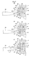
Fig. 7(b) is another sectional view of a primary portion for explaining a process of removing the lid element; -
Fig. 7(c) is a further sectional view of a primary portion for explaining a process of removing the lid element; - An embodiment of the present invention will be described hereinafter in reference to the accompanying drawings.
-
Figs. 1 and2 show a terminal box for a solar cell module in accordance with the present invention. The terminal box comprises abox casing 2 made of resin including a pair of metal terminal elements 1 (seeFig. 3 ) incorporated into the interior of the casing, alid element 4 made of resin for closing anopening 3 of thebox casing 2, and anengaging mechanism 7 for fixedly engaging anengaging element 5 provided in thelid element 4 with an engagedelement 6 provided in thebox casing 2 by pressing thelid element 4 against thebox casing 2. - As shown in
Fig. 3 , thebox casing 2 receives a pair ofoutput cables 8 connected to a capacitor, for example, and connects them to theterminal elements 1, respectively. At a bottom of thebox casing 2 is formed aninput cable inlet 9 for receiving a pair of input cables (not shown) connected to the solar cell module so that the input cables are connected to theterminal elements 1, respectively. - The
terminal elements 1 are fixed through terminal fixing clicks 10 integrally formed with an inner bottom portion of thebox casing 2. Theterminal elements 1 are connected to each other through a reverse-current short-circuit diode 11. - As shown in
Fig. 4 , theoutput cables 8 are inserted intotubular members 12 integrally formed with thebox casing 2 and connected to theterminal elements 1. - A gap between each
tubular member 12 and eachoutput cable 8 is closed by acable packing 13 attached to an inner side of thetubular member 12 to prevent entry of water. Thecable packing 13 is fastened to theoutput cables 8 through acap 14 screwed to thetubular member 12. - As shown in
Fig. 5 , thelid element 4 has a fittingtubular element 16 integrally formed with an inner side thereof and being fitted into aninner periphery 15 of the opening of thebox casing 2. A rubber O-ring 17 acting as a waterproof seal element is fitted into a circumferential groove formed in an outer periphery of the fittingtubular element 16 at an interface between the outer periphery of the fittingtubular element 16 and the openinginner periphery 15. - The
lid element 4 has a plurality ofvents 18 formed therein. As shown inFig. 5 , awaterproof sheet 19 for covering thevents 18 is affixed to an inner surface of thelid element 4 through an adhesive to prevent water from entering from thevents 18. - As shown in
Figs. 1 and2 , the engagingmechanism 7 includes a pair of theengaging elements 5 made of resin, and integrally formed with and symmetrically provided in an outer peripheral portion of thelid element 4 to oppose with each other, and a pair ofengaged elements 6 made of resin, and integrally formed with and symmetrically provided in an outer peripheral portion of thebox casing 2 to oppose with each other. - Each of the
engaging elements 5 has a plate-like projectingpiece 21 extending in a pressing direction of thelid element 4 along anextension 20 extending from a side edge portion of thelid element 4, and an engagingpawl 23 extending in a direction vertical to the extending direction of the projectingpiece 21 and provided in part of the projectingpiece 21 other than adistal end portion 22 of the projectingpiece 21. - Each of the engaged
elements 6 has a receivinghole 24 that opens toward an outer side of thebox casing 2 and allows thedistal end portion 22 of the projectingpiece 21 to be exposed to the outside when engaged with the engagingpawl 23. - More particularly, each
engaged element 6 has a pair ofvertical ribs 25 extending along the pressing direction, a connectingrib 26 provided in an outer surface of thebox casing 2 for connecting the pair ofvertical ribs 25 at distal end portions thereof in the pressing direction, and an intermediate plate-like beam element 27 spaced apart from the outer surface of thebox casing 2 for connecting of thevertical ribs 25 at intermediate portions thereof. - The above arrangement provides an inserting
hole 28, to which the projectingpiece 21 is inserted until the engagingpawl 23 comes out of the insert hole. The insertinghole 28 is formed between the intermediate plate-like beam element 27 and the outer surface of thebox casing 2 to form the receivinghole 24 surrounded by the pair ofvertical ribs 25, connectingrib 26 and intermediate plate-like beam element 27. The engagingpawl 23 coming out of the insertinghole 28 is engageable with the intermediate plate-like beam element 27. - A projecting height H (see
Fig. 6(a) ) of the engagingpawl 23 from the projectingpiece 21 is smaller than a depth D (seeFig. 6(b) ) of an inner wall portion of an inner wall surface of the receivinghole 24 formed by the intermediate plate-like beam element 27 engaged with the engagingpawl 23. This arrangement prevents a distal end of the engagingpawl 23 engaged with the intermediate plate-like beam element 27 from projecting outward of the intermediate plate-like beam element 27. - When the
lid element 4 is pressed against thebox casing 2 with the fittingtubular element 16 being fitted into theinner periphery 15 of theopening 3, the projectingpieces 21 of the pair ofengaging elements 5 are substantially concurrently inserted into the insertingholes 28 of the pair ofengaged elements 6, respectively. - A gap between the distal ends of the engaging
pawls 23 in the oppositeengaging elements 5 is larger than a gap between the intermediate plate-like beam elements 27 in the opposite engagedelements 6. This allows the respective projectingpieces 21 to be inserted into the receiving holes 28 together with the engagingpawls 23 by being elastically deformed toward thebox casing 2. - The
distal end portion 22 of the projectingpiece 21 has a wall surface positioned adjacent a downward side of the inner wall surface of the receivinghole 24 in the direction of pressing the projectingpiece 21. The wall surface acts as abottom surface 29 opposed to a top surface of the connecting rib 26 (seeFig. 6 ) and is formed by the thickness of thedistal end portion 22 of the projectingpiece 21 that has a thickness smaller than the thickness of the top surface of the engagingpawl 23 of the projectingpiece 21 measured from the outer surface of thelid element 4. - A restricting
portion 30 is provided in thebox casing 2 for restricting an amount of displacement of the projectingpiece 21 within an elastic range when the engagingpawl 23 or thedistal end portion 22 of the projectingpiece 21 is depressed through the receivinghole 24 in disengaging the engagingpawl 23 from the receivinghole 24. In the current embodiment, the restrictingportion 30 is formed by an outer surface portion of thebox casing 2 facing the receivinghole 24. - At a forward portion of the engaging
pawl 23 in the inserting direction toward the receivinghole 24 is formed a contacting surface 31 (seeFig. 6 ) that inclines closer to the projectingpiece 21 adjacent the forward portion thereof in the inserting direction. On the other hand, the intermediate plate-like beam element 27 has a guide surface 32 (seeFig. 6 ), to which the contactingsurface 31 is pressed. Theguide surface 32 inclines closer to thebox casing 2 adjacent the forward portion thereof in the inserting direction (adjacent the bottom of the box casing 2). - A process for fixedly engaging the
lid element 4 with thebox casing 2 through the engagingmechanism 7 is described hereinafter in reference toFig. 6 . - As shown in
Fig. 6(a) , thelid element 4 having the O-ring 17 attached to the circumferential groove of the fittingtubular element 16 is pressed against thebox casing 2 with thelid element 4 being faced with thebox casing 2 so that the opposite projectingpieces 21 face the opposite receiving holes 28, respectively. - In this state, as shown in
Fig. 6(b) , the contact surfaces 31 of the opposite engagingpawls 23 are pressed against the guide surfaces 32 of the intermediate plate-like beam elements 27. This allows the opposite projectingpieces 21 to be elastically deformed toward thebox casing 2 and inserted into the receiving holes 28 together with the engagingpawls 23. - When the engaging
pawls 23 come out through the receiving holes 28, each projectingpiece 21 is restorably deformed and each engagingpawl 23 is fixedly engaged with a corner of the intermediate plate-like beam element 27 at the forward portion thereof in the pressing direction. This allows thelid element 4 to be rigidly fixedly engaged with thebox casing 2. - A process of removing the
lid element 4 fixedly engaged with thebox casing 2 is described hereinafter in reference toFig. 7 . - As shown in
Fig. 7(a) , a flat distal end of a control rod (control element) 33 is inserted between thebottom surface 29 of the projectingpiece 21 and the top surface of the connectingrib 26 through the receivinghole 24. A standard screwdriver, for example, may be used as thecontrol rod 33. - Next, as shown in
Fig. 7(b) , thedistal end portion 22 of the projectingpiece 21 is pressed toward a disengaging direction, that is, toward thebox casing 2 with the distal end of thecontrol rod 33 thereby elastically deforming the projectingpiece 21 so that the projectingpiece 21 fits into the receivinghole 28 together with the engagingpawl 23. - Then, as shown in
Fig. 7(c) , thecontrol rod 33 is rotated with the connectingrib 26 being served as a reaction force receiver, thereby moving the projectingpiece 21 in a direction opposite from the direction of pressing thelid element 4, that is, in a direction of inserting the projectingpiece 21 into the receivinghole 28 along with the engagingpawl 23. As a result, thelid element 4 is raised from thebox casing 2. - A series of operations shown in
Figs. 7(a) to 7(c) may be performed at the oppositeengaging elements 5, separately or together, thereby removing thelid element 4 from thebox casing 2.
Claims (5)
- A terminal box comprising:a box casing (2) including terminal elements incorporated into the interior thereof;a lid element (4) for closing an opening (3) of the box casing (2); andan engaging mechanism (7) for fixedly engaging an engaging element (5) provided in the lid element (4) with an engaged element (6) provided in the box casing (2) by pressing the lid element (4) against the box casing (2);characterized in thatthe engaging element (5) includes a projecting piece (21) extending in a pressing direction of the lid member (4), and an engaging pawl (23) extending in a direction vertical to the extending direction of the projecting piece (21) and provided in part of the projecting piece (21) other than a distal end portion (22) of the projecting piece (21), andthat the engaged element (6) has a receiving hole (24) opening toward an outer side of the box casing (2) and allowing the distal end portion (22) of the projecting piece (21) to be exposed to the outside when engaged with the engaging pawl (23).
- The terminal box as claimed in claim 1, characterized in that the projecting piece (21) has a bottom surface (29) at the distal end portion (22) thereof opposed to a wall surface portion of an inner wall surface of the receiving hole (24) positioned adjacent a downward side of the projecting piece in the pressing direction.
- The terminal box as claimed in claim 1 or 2, characterized in that the terminal box further compres a restricting portion (30) for restricting displacement of the projecting piece (21) to a predetermined position when the engaging pawl (23) or the distal end portion (22) of the projecting piece (21) is depressed through the receiving hole (24) in disengaging the engaging pawl (23) from the receiving hole (24).
- The terminal box as claimed in claim 3, characterized in that the restricting portion (30) is provided in the box casing (2).
- The terminal box as claimed in any one of claims 1 to 4, characterized in that the engaging pawl (23) has a projecting height (H) smaller than a depth-wise width (D) of the inner wall surface of the receiving hole (24).
Applications Claiming Priority (1)
| Application Number | Priority Date | Filing Date | Title |
|---|---|---|---|
| JP2009231405A JP5281534B2 (en) | 2009-10-05 | 2009-10-05 | Terminal box |
Publications (3)
| Publication Number | Publication Date |
|---|---|
| EP2312711A2 true EP2312711A2 (en) | 2011-04-20 |
| EP2312711A3 EP2312711A3 (en) | 2013-07-10 |
| EP2312711B1 EP2312711B1 (en) | 2016-07-27 |
Family
ID=43629638
Family Applications (1)
| Application Number | Title | Priority Date | Filing Date |
|---|---|---|---|
| EP10013259.6A Not-in-force EP2312711B1 (en) | 2009-10-05 | 2010-10-04 | Terminal box |
Country Status (4)
| Country | Link |
|---|---|
| US (1) | US8648264B2 (en) |
| EP (1) | EP2312711B1 (en) |
| JP (1) | JP5281534B2 (en) |
| CN (1) | CN102035103B (en) |
Cited By (1)
| Publication number | Priority date | Publication date | Assignee | Title |
|---|---|---|---|---|
| WO2022223637A1 (en) * | 2021-04-22 | 2022-10-27 | Belimo Holding Ag | Room unit for an hvac system |
Families Citing this family (44)
| Publication number | Priority date | Publication date | Assignee | Title |
|---|---|---|---|---|
| JP5550462B2 (en) * | 2010-06-18 | 2014-07-16 | キヤノン株式会社 | Process cartridge |
| US9812684B2 (en) | 2010-11-09 | 2017-11-07 | GM Global Technology Operations LLC | Using elastic averaging for alignment of battery stack, fuel cell stack, or other vehicle assembly |
| JP5830858B2 (en) * | 2010-12-24 | 2015-12-09 | 株式会社豊田自動織機 | Electronics |
| DE112011105250B4 (en) * | 2011-05-18 | 2018-08-30 | Toyota Jidosha Kabushiki Kaisha | board device |
| US9476251B2 (en) | 2011-08-19 | 2016-10-25 | Aerovironment, Inc. | Water-tight compartment with removable hatch and two-sided gel seal for multiple conduit access |
| JP5753032B2 (en) * | 2011-09-02 | 2015-07-22 | 日東電工株式会社 | Joining member having ventilation function and joining structure using the same |
| WO2013080669A1 (en) * | 2011-11-28 | 2013-06-06 | Necカシオモバイルコミュニケーションズ株式会社 | Dustproofing structure and electronic device |
| JP5799814B2 (en) * | 2012-01-10 | 2015-10-28 | 富士通株式会社 | Electronics |
| DE202012101254U1 (en) * | 2012-04-05 | 2012-07-11 | Rpc Bramlage Gmbh | container |
| CN103458638A (en) * | 2012-06-01 | 2013-12-18 | 深圳富泰宏精密工业有限公司 | Locking structure and electronic device using same |
| CN103838342A (en) * | 2012-11-23 | 2014-06-04 | 鸿富锦精密工业(深圳)有限公司 | Power source |
| US9108772B2 (en) * | 2013-03-15 | 2015-08-18 | Scientific Specialties, Inc. | Container latching systems for one-handed operation |
| CN103199470B (en) * | 2013-03-29 | 2015-07-15 | 国家电网公司 | Metering terminal box |
| US9863454B2 (en) | 2013-08-07 | 2018-01-09 | GM Global Technology Operations LLC | Alignment system for providing precise alignment and retention of components of a sealable compartment |
| US9669774B2 (en) | 2013-10-11 | 2017-06-06 | GM Global Technology Operations LLC | Reconfigurable vehicle interior assembly |
| KR20150049259A (en) * | 2013-10-29 | 2015-05-08 | 삼성에스디아이 주식회사 | Junction box and photovoltaic module comprising the same |
| US9657807B2 (en) | 2014-04-23 | 2017-05-23 | GM Global Technology Operations LLC | System for elastically averaging assembly of components |
| US20150375798A1 (en) * | 2014-06-30 | 2015-12-31 | GM Global Technology Operations LLC | Elastically averaged alignment systems and methods |
| US9758110B2 (en) | 2015-01-12 | 2017-09-12 | GM Global Technology Operations LLC | Coupling system |
| JP5885134B1 (en) * | 2015-07-06 | 2016-03-15 | 住友電装株式会社 | Electric wire housing protector |
| WO2017100919A1 (en) * | 2015-12-14 | 2017-06-22 | Think Tank Water Heaters Ltd. | Electric hot water heater energy management |
| DE202016101880U1 (en) * | 2016-04-11 | 2016-04-27 | Häfele Berlin Gmbh & Co Kg | Fitting for detachably connecting two furniture parts |
| DE102016220022B4 (en) * | 2016-10-13 | 2021-12-09 | Vitesco Technologies GmbH | Combination of a plug with a cover |
| US20180223570A1 (en) * | 2017-02-03 | 2018-08-09 | Robert Warren Becker | Theft prevention saddlebag receiver latch bracket |
| EP3589846B1 (en) * | 2017-02-28 | 2022-06-15 | 3M Innovative Properties Company | Attachment device and related methods |
| CN207316168U (en) * | 2017-05-05 | 2018-05-04 | 卡瓦尼亚集团股份公司 | It is a kind of to be used for the gas station of fuel gas transmission to utensil |
| JP6793613B2 (en) * | 2017-09-15 | 2020-12-02 | 矢崎総業株式会社 | Cover locking structure of electrical junction box |
| WO2019057306A1 (en) * | 2017-09-25 | 2019-03-28 | HELLA GmbH & Co. KGaA | Method for fitting a snap fit arrangement and a corresponding fitting arrangement |
| US11399441B2 (en) * | 2017-12-21 | 2022-07-26 | Allbro (Pty) Ltd | Security enclosure |
| JP6739469B2 (en) * | 2018-05-15 | 2020-08-12 | 三菱電機株式会社 | Waterproof board housing |
| US12034398B2 (en) * | 2019-05-31 | 2024-07-09 | Sunpower Corporation | Junction box for a photovoltaic module mounting assembly |
| JP7214615B2 (en) * | 2019-12-05 | 2023-01-30 | 株式会社東芝 | Connected device |
| JP7382865B2 (en) * | 2020-03-18 | 2023-11-17 | 古河電気工業株式会社 | electrical junction box |
| PL245343B1 (en) * | 2020-06-09 | 2024-07-01 | Reend Spolka Z Ograniczona Odpowiedzialnoscia | Snap-on, inseparable connection of the lid with a container intended especially for drinks |
| US11357120B2 (en) * | 2020-09-11 | 2022-06-07 | Phoenix Contact Development and Manufacturing, Inc. | Electrical component enclosure and method of use |
| JP7577585B2 (en) * | 2021-03-25 | 2024-11-05 | 株式会社デンソーテン | Assembly Structure |
| USD1037801S1 (en) * | 2021-06-14 | 2024-08-06 | Norman R. Byrne | Housing for electrical junction |
| CN115968155A (en) * | 2021-10-13 | 2023-04-14 | 台达电子工业股份有限公司 | Electronic device waterproof structure |
| US12349294B2 (en) * | 2022-03-11 | 2025-07-01 | Suprema Inc. | Terminal apparatus assembly and terminal equipment including same |
| EP4257505A1 (en) | 2022-04-06 | 2023-10-11 | Crativ Solutions, Inc | Latch mechanism for a child-resistant storage case |
| US12349293B2 (en) * | 2022-10-13 | 2025-07-01 | Industrial Technology Research Institute | Combined power module |
| TWM641402U (en) * | 2023-01-03 | 2023-05-21 | 台灣福興工業股份有限公司 | Electric lock and housing thereof |
| TWI873675B (en) * | 2023-06-08 | 2025-02-21 | 啟碁科技股份有限公司 | Detachable device, detachable device set and latching structure |
| JP2025012799A (en) * | 2023-07-14 | 2025-01-24 | 株式会社東芝 | Semiconductor Device |
Citations (1)
| Publication number | Priority date | Publication date | Assignee | Title |
|---|---|---|---|---|
| JPH0314628B2 (en) | 1980-10-16 | 1991-02-27 | Toshiba Machine Co Ltd |
Family Cites Families (18)
| Publication number | Priority date | Publication date | Assignee | Title |
|---|---|---|---|---|
| US4212415A (en) * | 1978-01-09 | 1980-07-15 | Refreshment Machinery Incorporated | Housing and module therefor |
| JPS61123576U (en) * | 1985-01-22 | 1986-08-04 | ||
| US4964661A (en) * | 1989-06-30 | 1990-10-23 | Poget Computer Corporation | Two-part casing latching mechanism |
| US5100015A (en) * | 1991-07-05 | 1992-03-31 | Electro-Wire Products, Inc. | Latch unit for container and mating lid |
| US5346069A (en) * | 1992-09-24 | 1994-09-13 | Intini Thomas D | Container |
| US5356017A (en) * | 1992-10-28 | 1994-10-18 | Aptargroup, Inc. | Child resistant closure with recessed latch |
| JP2582779Y2 (en) * | 1993-10-12 | 1998-10-08 | 住友電装株式会社 | Lock structure of electrical junction box |
| US5577779A (en) * | 1994-12-22 | 1996-11-26 | Yazaki Corporation | Snap fit lock with release feature |
| JP3014628B2 (en) | 1995-09-19 | 2000-02-28 | キヤノン株式会社 | Terminal box for solar cell |
| TW353263B (en) * | 1996-11-21 | 1999-02-21 | Koninkl Philips Electronics Nv | Detachable connection between two housing sections |
| US5871113A (en) * | 1997-09-10 | 1999-02-16 | Bodrick Washroom Equipment, Inc. | Lid for a container |
| US6398594B1 (en) * | 2001-03-12 | 2002-06-04 | Hubbell Incorporated | Two-piece electrical receptacle housing having a barbed post and resilient hoop connection |
| US6772902B1 (en) * | 2003-06-20 | 2004-08-10 | Colin White | One-piece molded child-proof container |
| JP2005044919A (en) * | 2003-07-25 | 2005-02-17 | Fujitsu Access Ltd | Cabinet |
| ITFI20050185A1 (en) * | 2005-08-31 | 2007-03-01 | Belisario Pini | CASE FOR ELECTRICAL CONNECTIONS AND PROCEDURE FOR MANUFACTURING A SHEET |
| US7413479B1 (en) * | 2007-02-16 | 2008-08-19 | Delphi Technologies, Inc. | Cover lock |
| CN201031554Y (en) | 2007-05-08 | 2008-03-05 | 康联精密机电(深圳)有限公司 | Padlock structure and unlocking key thereof |
| TWM350847U (en) * | 2008-07-21 | 2009-02-11 | Hon Hai Prec Ind Co Ltd | Electrical connector |
-
2009
- 2009-10-05 JP JP2009231405A patent/JP5281534B2/en not_active Expired - Fee Related
-
2010
- 2010-09-30 CN CN201010503675.XA patent/CN102035103B/en not_active Expired - Fee Related
- 2010-10-04 EP EP10013259.6A patent/EP2312711B1/en not_active Not-in-force
- 2010-10-04 US US12/897,127 patent/US8648264B2/en not_active Expired - Fee Related
Patent Citations (1)
| Publication number | Priority date | Publication date | Assignee | Title |
|---|---|---|---|---|
| JPH0314628B2 (en) | 1980-10-16 | 1991-02-27 | Toshiba Machine Co Ltd |
Cited By (2)
| Publication number | Priority date | Publication date | Assignee | Title |
|---|---|---|---|---|
| WO2022223637A1 (en) * | 2021-04-22 | 2022-10-27 | Belimo Holding Ag | Room unit for an hvac system |
| US12331947B2 (en) | 2021-04-22 | 2025-06-17 | Belimo Holding Ag | Room unit for an HVAC system |
Also Published As
| Publication number | Publication date |
|---|---|
| EP2312711B1 (en) | 2016-07-27 |
| US20110079413A1 (en) | 2011-04-07 |
| US8648264B2 (en) | 2014-02-11 |
| EP2312711A3 (en) | 2013-07-10 |
| JP2011081942A (en) | 2011-04-21 |
| CN102035103B (en) | 2014-01-01 |
| CN102035103A (en) | 2011-04-27 |
| JP5281534B2 (en) | 2013-09-04 |
Similar Documents
| Publication | Publication Date | Title |
|---|---|---|
| US8648264B2 (en) | Terminal box | |
| EP2014930B1 (en) | Article installation device | |
| CN103189674B (en) | Plugs | |
| US9120509B2 (en) | Hole plug | |
| US7820910B1 (en) | Adapter for electrical outlet cover | |
| EP2733794A1 (en) | Connector provided with a connecting position assurance device | |
| US8361643B2 (en) | Battery cover latch mechanism and portable electronic device using same | |
| EP2902689A1 (en) | Connector | |
| US7916477B2 (en) | Battery cover latch mechanism and portable electronic device using same | |
| KR101765571B1 (en) | Driving device and structure of fixing the same | |
| CN100385127C (en) | One-touch terminal for fixing control cables | |
| US10873156B2 (en) | Connector and connector assembly | |
| JP5213361B2 (en) | Pack battery | |
| EP3402004B1 (en) | Terminal locking structure and connector | |
| JP6287988B2 (en) | connector | |
| JP2003502886A (en) | housing | |
| US10153578B2 (en) | Connector structure | |
| KR101800547B1 (en) | Connector | |
| JP2001307830A (en) | Lock detection structure of connector | |
| KR102796356B1 (en) | Connector | |
| JP4965243B2 (en) | Lock mechanism | |
| JP2016127640A (en) | Hermetically sealed box and hermetically sealing structure | |
| JPH08139472A (en) | Structure for mounting electronic device on rail | |
| JP2004221121A (en) | Hook mounting structure and housing structure using this hook mounting structure | |
| JP2009181933A (en) | Connector |
Legal Events
| Date | Code | Title | Description |
|---|---|---|---|
| PUAI | Public reference made under article 153(3) epc to a published international application that has entered the european phase |
Free format text: ORIGINAL CODE: 0009012 |
|
| AK | Designated contracting states |
Kind code of ref document: A2 Designated state(s): AL AT BE BG CH CY CZ DE DK EE ES FI FR GB GR HR HU IE IS IT LI LT LU LV MC MK MT NL NO PL PT RO RS SE SI SK SM TR |
|
| AX | Request for extension of the european patent |
Extension state: BA ME |
|
| PUAL | Search report despatched |
Free format text: ORIGINAL CODE: 0009013 |
|
| AK | Designated contracting states |
Kind code of ref document: A3 Designated state(s): AL AT BE BG CH CY CZ DE DK EE ES FI FR GB GR HR HU IE IS IT LI LT LU LV MC MK MT NL NO PL PT RO RS SE SI SK SM TR |
|
| AX | Request for extension of the european patent |
Extension state: BA ME |
|
| RIC1 | Information provided on ipc code assigned before grant |
Ipc: H02G 3/06 20060101AFI20130603BHEP Ipc: H02G 3/16 20060101ALI20130603BHEP Ipc: H02G 3/14 20060101ALI20130603BHEP Ipc: H01R 9/00 20060101ALI20130603BHEP Ipc: H02G 3/08 20060101ALI20130603BHEP |
|
| 17P | Request for examination filed |
Effective date: 20131123 |
|
| RBV | Designated contracting states (corrected) |
Designated state(s): AL AT BE BG CH CY CZ DE DK EE ES FI FR GB GR HR HU IE IS IT LI LT LU LV MC MK MT NL NO PL PT RO RS SE SI SK SM TR |
|
| 17Q | First examination report despatched |
Effective date: 20140602 |
|
| GRAP | Despatch of communication of intention to grant a patent |
Free format text: ORIGINAL CODE: EPIDOSNIGR1 |
|
| INTG | Intention to grant announced |
Effective date: 20160307 |
|
| GRAS | Grant fee paid |
Free format text: ORIGINAL CODE: EPIDOSNIGR3 |
|
| GRAA | (expected) grant |
Free format text: ORIGINAL CODE: 0009210 |
|
| AK | Designated contracting states |
Kind code of ref document: B1 Designated state(s): AL AT BE BG CH CY CZ DE DK EE ES FI FR GB GR HR HU IE IS IT LI LT LU LV MC MK MT NL NO PL PT RO RS SE SI SK SM TR |
|
| REG | Reference to a national code |
Ref country code: GB Ref legal event code: FG4D |
|
| REG | Reference to a national code |
Ref country code: CH Ref legal event code: EP |
|
| REG | Reference to a national code |
Ref country code: AT Ref legal event code: REF Ref document number: 816482 Country of ref document: AT Kind code of ref document: T Effective date: 20160815 |
|
| REG | Reference to a national code |
Ref country code: IE Ref legal event code: FG4D |
|
| REG | Reference to a national code |
Ref country code: DE Ref legal event code: R096 Ref document number: 602010034978 Country of ref document: DE |
|
| REG | Reference to a national code |
Ref country code: FR Ref legal event code: PLFP Year of fee payment: 7 |
|
| REG | Reference to a national code |
Ref country code: LT Ref legal event code: MG4D |
|
| REG | Reference to a national code |
Ref country code: NL Ref legal event code: MP Effective date: 20160727 |
|
| REG | Reference to a national code |
Ref country code: AT Ref legal event code: MK05 Ref document number: 816482 Country of ref document: AT Kind code of ref document: T Effective date: 20160727 |
|
| PG25 | Lapsed in a contracting state [announced via postgrant information from national office to epo] |
Ref country code: RS Free format text: LAPSE BECAUSE OF FAILURE TO SUBMIT A TRANSLATION OF THE DESCRIPTION OR TO PAY THE FEE WITHIN THE PRESCRIBED TIME-LIMIT Effective date: 20160727 Ref country code: FI Free format text: LAPSE BECAUSE OF FAILURE TO SUBMIT A TRANSLATION OF THE DESCRIPTION OR TO PAY THE FEE WITHIN THE PRESCRIBED TIME-LIMIT Effective date: 20160727 Ref country code: NO Free format text: LAPSE BECAUSE OF FAILURE TO SUBMIT A TRANSLATION OF THE DESCRIPTION OR TO PAY THE FEE WITHIN THE PRESCRIBED TIME-LIMIT Effective date: 20161027 Ref country code: IT Free format text: LAPSE BECAUSE OF FAILURE TO SUBMIT A TRANSLATION OF THE DESCRIPTION OR TO PAY THE FEE WITHIN THE PRESCRIBED TIME-LIMIT Effective date: 20160727 Ref country code: LT Free format text: LAPSE BECAUSE OF FAILURE TO SUBMIT A TRANSLATION OF THE DESCRIPTION OR TO PAY THE FEE WITHIN THE PRESCRIBED TIME-LIMIT Effective date: 20160727 Ref country code: NL Free format text: LAPSE BECAUSE OF FAILURE TO SUBMIT A TRANSLATION OF THE DESCRIPTION OR TO PAY THE FEE WITHIN THE PRESCRIBED TIME-LIMIT Effective date: 20160727 Ref country code: IS Free format text: LAPSE BECAUSE OF FAILURE TO SUBMIT A TRANSLATION OF THE DESCRIPTION OR TO PAY THE FEE WITHIN THE PRESCRIBED TIME-LIMIT Effective date: 20161127 Ref country code: HR Free format text: LAPSE BECAUSE OF FAILURE TO SUBMIT A TRANSLATION OF THE DESCRIPTION OR TO PAY THE FEE WITHIN THE PRESCRIBED TIME-LIMIT Effective date: 20160727 |
|
| PG25 | Lapsed in a contracting state [announced via postgrant information from national office to epo] |
Ref country code: GR Free format text: LAPSE BECAUSE OF FAILURE TO SUBMIT A TRANSLATION OF THE DESCRIPTION OR TO PAY THE FEE WITHIN THE PRESCRIBED TIME-LIMIT Effective date: 20161028 Ref country code: BE Free format text: LAPSE BECAUSE OF NON-PAYMENT OF DUE FEES Effective date: 20160727 Ref country code: PL Free format text: LAPSE BECAUSE OF FAILURE TO SUBMIT A TRANSLATION OF THE DESCRIPTION OR TO PAY THE FEE WITHIN THE PRESCRIBED TIME-LIMIT Effective date: 20160727 Ref country code: SE Free format text: LAPSE BECAUSE OF FAILURE TO SUBMIT A TRANSLATION OF THE DESCRIPTION OR TO PAY THE FEE WITHIN THE PRESCRIBED TIME-LIMIT Effective date: 20160727 Ref country code: PT Free format text: LAPSE BECAUSE OF FAILURE TO SUBMIT A TRANSLATION OF THE DESCRIPTION OR TO PAY THE FEE WITHIN THE PRESCRIBED TIME-LIMIT Effective date: 20161128 Ref country code: LV Free format text: LAPSE BECAUSE OF FAILURE TO SUBMIT A TRANSLATION OF THE DESCRIPTION OR TO PAY THE FEE WITHIN THE PRESCRIBED TIME-LIMIT Effective date: 20160727 Ref country code: ES Free format text: LAPSE BECAUSE OF FAILURE TO SUBMIT A TRANSLATION OF THE DESCRIPTION OR TO PAY THE FEE WITHIN THE PRESCRIBED TIME-LIMIT Effective date: 20160727 Ref country code: AT Free format text: LAPSE BECAUSE OF FAILURE TO SUBMIT A TRANSLATION OF THE DESCRIPTION OR TO PAY THE FEE WITHIN THE PRESCRIBED TIME-LIMIT Effective date: 20160727 |
|
| PG25 | Lapsed in a contracting state [announced via postgrant information from national office to epo] |
Ref country code: RO Free format text: LAPSE BECAUSE OF FAILURE TO SUBMIT A TRANSLATION OF THE DESCRIPTION OR TO PAY THE FEE WITHIN THE PRESCRIBED TIME-LIMIT Effective date: 20160727 Ref country code: EE Free format text: LAPSE BECAUSE OF FAILURE TO SUBMIT A TRANSLATION OF THE DESCRIPTION OR TO PAY THE FEE WITHIN THE PRESCRIBED TIME-LIMIT Effective date: 20160727 |
|
| REG | Reference to a national code |
Ref country code: DE Ref legal event code: R097 Ref document number: 602010034978 Country of ref document: DE |
|
| PG25 | Lapsed in a contracting state [announced via postgrant information from national office to epo] |
Ref country code: BG Free format text: LAPSE BECAUSE OF FAILURE TO SUBMIT A TRANSLATION OF THE DESCRIPTION OR TO PAY THE FEE WITHIN THE PRESCRIBED TIME-LIMIT Effective date: 20161027 Ref country code: SM Free format text: LAPSE BECAUSE OF FAILURE TO SUBMIT A TRANSLATION OF THE DESCRIPTION OR TO PAY THE FEE WITHIN THE PRESCRIBED TIME-LIMIT Effective date: 20160727 Ref country code: SK Free format text: LAPSE BECAUSE OF FAILURE TO SUBMIT A TRANSLATION OF THE DESCRIPTION OR TO PAY THE FEE WITHIN THE PRESCRIBED TIME-LIMIT Effective date: 20160727 Ref country code: CZ Free format text: LAPSE BECAUSE OF FAILURE TO SUBMIT A TRANSLATION OF THE DESCRIPTION OR TO PAY THE FEE WITHIN THE PRESCRIBED TIME-LIMIT Effective date: 20160727 Ref country code: DK Free format text: LAPSE BECAUSE OF FAILURE TO SUBMIT A TRANSLATION OF THE DESCRIPTION OR TO PAY THE FEE WITHIN THE PRESCRIBED TIME-LIMIT Effective date: 20160727 |
|
| REG | Reference to a national code |
Ref country code: CH Ref legal event code: PL |
|
| PLBE | No opposition filed within time limit |
Free format text: ORIGINAL CODE: 0009261 |
|
| STAA | Information on the status of an ep patent application or granted ep patent |
Free format text: STATUS: NO OPPOSITION FILED WITHIN TIME LIMIT |
|
| GBPC | Gb: european patent ceased through non-payment of renewal fee |
Effective date: 20161027 |
|
| 26N | No opposition filed |
Effective date: 20170502 |
|
| REG | Reference to a national code |
Ref country code: IE Ref legal event code: MM4A |
|
| PG25 | Lapsed in a contracting state [announced via postgrant information from national office to epo] |
Ref country code: GB Free format text: LAPSE BECAUSE OF NON-PAYMENT OF DUE FEES Effective date: 20161027 Ref country code: LI Free format text: LAPSE BECAUSE OF NON-PAYMENT OF DUE FEES Effective date: 20161031 Ref country code: CH Free format text: LAPSE BECAUSE OF NON-PAYMENT OF DUE FEES Effective date: 20161031 |
|
| PG25 | Lapsed in a contracting state [announced via postgrant information from national office to epo] |
Ref country code: LU Free format text: LAPSE BECAUSE OF NON-PAYMENT OF DUE FEES Effective date: 20161004 Ref country code: SI Free format text: LAPSE BECAUSE OF FAILURE TO SUBMIT A TRANSLATION OF THE DESCRIPTION OR TO PAY THE FEE WITHIN THE PRESCRIBED TIME-LIMIT Effective date: 20160727 |
|
| REG | Reference to a national code |
Ref country code: FR Ref legal event code: PLFP Year of fee payment: 8 |
|
| PG25 | Lapsed in a contracting state [announced via postgrant information from national office to epo] |
Ref country code: IE Free format text: LAPSE BECAUSE OF NON-PAYMENT OF DUE FEES Effective date: 20161004 |
|
| PG25 | Lapsed in a contracting state [announced via postgrant information from national office to epo] |
Ref country code: CY Free format text: LAPSE BECAUSE OF FAILURE TO SUBMIT A TRANSLATION OF THE DESCRIPTION OR TO PAY THE FEE WITHIN THE PRESCRIBED TIME-LIMIT Effective date: 20160727 Ref country code: HU Free format text: LAPSE BECAUSE OF FAILURE TO SUBMIT A TRANSLATION OF THE DESCRIPTION OR TO PAY THE FEE WITHIN THE PRESCRIBED TIME-LIMIT; INVALID AB INITIO Effective date: 20101004 |
|
| PG25 | Lapsed in a contracting state [announced via postgrant information from national office to epo] |
Ref country code: MC Free format text: LAPSE BECAUSE OF FAILURE TO SUBMIT A TRANSLATION OF THE DESCRIPTION OR TO PAY THE FEE WITHIN THE PRESCRIBED TIME-LIMIT Effective date: 20160727 Ref country code: TR Free format text: LAPSE BECAUSE OF FAILURE TO SUBMIT A TRANSLATION OF THE DESCRIPTION OR TO PAY THE FEE WITHIN THE PRESCRIBED TIME-LIMIT Effective date: 20160727 Ref country code: MK Free format text: LAPSE BECAUSE OF FAILURE TO SUBMIT A TRANSLATION OF THE DESCRIPTION OR TO PAY THE FEE WITHIN THE PRESCRIBED TIME-LIMIT Effective date: 20160727 Ref country code: MT Free format text: LAPSE BECAUSE OF NON-PAYMENT OF DUE FEES Effective date: 20161031 |
|
| REG | Reference to a national code |
Ref country code: FR Ref legal event code: PLFP Year of fee payment: 9 |
|
| PG25 | Lapsed in a contracting state [announced via postgrant information from national office to epo] |
Ref country code: AL Free format text: LAPSE BECAUSE OF FAILURE TO SUBMIT A TRANSLATION OF THE DESCRIPTION OR TO PAY THE FEE WITHIN THE PRESCRIBED TIME-LIMIT Effective date: 20160727 |
|
| PGFP | Annual fee paid to national office [announced via postgrant information from national office to epo] |
Ref country code: DE Payment date: 20210924 Year of fee payment: 12 |
|
| PGFP | Annual fee paid to national office [announced via postgrant information from national office to epo] |
Ref country code: FR Payment date: 20211021 Year of fee payment: 12 |
|
| REG | Reference to a national code |
Ref country code: DE Ref legal event code: R119 Ref document number: 602010034978 Country of ref document: DE |
|
| PG25 | Lapsed in a contracting state [announced via postgrant information from national office to epo] |
Ref country code: FR Free format text: LAPSE BECAUSE OF NON-PAYMENT OF DUE FEES Effective date: 20221031 Ref country code: DE Free format text: LAPSE BECAUSE OF NON-PAYMENT OF DUE FEES Effective date: 20230503 |