EP2312675A1 - Electrically conductive connection between electrode and terminal - Google Patents
Electrically conductive connection between electrode and terminal Download PDFInfo
- Publication number
- EP2312675A1 EP2312675A1 EP10177774A EP10177774A EP2312675A1 EP 2312675 A1 EP2312675 A1 EP 2312675A1 EP 10177774 A EP10177774 A EP 10177774A EP 10177774 A EP10177774 A EP 10177774A EP 2312675 A1 EP2312675 A1 EP 2312675A1
- Authority
- EP
- European Patent Office
- Prior art keywords
- terminal
- battery
- fixing member
- electrode
- corrosion resistance
- Prior art date
- Legal status (The legal status is an assumption and is not a legal conclusion. Google has not performed a legal analysis and makes no representation as to the accuracy of the status listed.)
- Granted
Links
Images



Classifications
-
- H—ELECTRICITY
- H01—ELECTRIC ELEMENTS
- H01M—PROCESSES OR MEANS, e.g. BATTERIES, FOR THE DIRECT CONVERSION OF CHEMICAL ENERGY INTO ELECTRICAL ENERGY
- H01M50/00—Constructional details or processes of manufacture of the non-active parts of electrochemical cells other than fuel cells, e.g. hybrid cells
- H01M50/50—Current conducting connections for cells or batteries
- H01M50/531—Electrode connections inside a battery casing
-
- H—ELECTRICITY
- H01—ELECTRIC ELEMENTS
- H01M—PROCESSES OR MEANS, e.g. BATTERIES, FOR THE DIRECT CONVERSION OF CHEMICAL ENERGY INTO ELECTRICAL ENERGY
- H01M50/00—Constructional details or processes of manufacture of the non-active parts of electrochemical cells other than fuel cells, e.g. hybrid cells
- H01M50/50—Current conducting connections for cells or batteries
- H01M50/543—Terminals
- H01M50/564—Terminals characterised by their manufacturing process
- H01M50/566—Terminals characterised by their manufacturing process by welding, soldering or brazing
-
- H—ELECTRICITY
- H01—ELECTRIC ELEMENTS
- H01M—PROCESSES OR MEANS, e.g. BATTERIES, FOR THE DIRECT CONVERSION OF CHEMICAL ENERGY INTO ELECTRICAL ENERGY
- H01M50/00—Constructional details or processes of manufacture of the non-active parts of electrochemical cells other than fuel cells, e.g. hybrid cells
- H01M50/50—Current conducting connections for cells or batteries
- H01M50/543—Terminals
- H01M50/562—Terminals characterised by the material
-
- H—ELECTRICITY
- H01—ELECTRIC ELEMENTS
- H01M—PROCESSES OR MEANS, e.g. BATTERIES, FOR THE DIRECT CONVERSION OF CHEMICAL ENERGY INTO ELECTRICAL ENERGY
- H01M50/00—Constructional details or processes of manufacture of the non-active parts of electrochemical cells other than fuel cells, e.g. hybrid cells
- H01M50/50—Current conducting connections for cells or batteries
- H01M50/531—Electrode connections inside a battery casing
- H01M50/534—Electrode connections inside a battery casing characterised by the material of the leads or tabs
-
- H—ELECTRICITY
- H01—ELECTRIC ELEMENTS
- H01M—PROCESSES OR MEANS, e.g. BATTERIES, FOR THE DIRECT CONVERSION OF CHEMICAL ENERGY INTO ELECTRICAL ENERGY
- H01M50/00—Constructional details or processes of manufacture of the non-active parts of electrochemical cells other than fuel cells, e.g. hybrid cells
- H01M50/50—Current conducting connections for cells or batteries
- H01M50/531—Electrode connections inside a battery casing
- H01M50/536—Electrode connections inside a battery casing characterised by the method of fixing the leads to the electrodes, e.g. by welding
-
- H—ELECTRICITY
- H01—ELECTRIC ELEMENTS
- H01M—PROCESSES OR MEANS, e.g. BATTERIES, FOR THE DIRECT CONVERSION OF CHEMICAL ENERGY INTO ELECTRICAL ENERGY
- H01M50/00—Constructional details or processes of manufacture of the non-active parts of electrochemical cells other than fuel cells, e.g. hybrid cells
- H01M50/50—Current conducting connections for cells or batteries
- H01M50/543—Terminals
- H01M50/547—Terminals characterised by the disposition of the terminals on the cells
- H01M50/55—Terminals characterised by the disposition of the terminals on the cells on the same side of the cell
-
- H—ELECTRICITY
- H01—ELECTRIC ELEMENTS
- H01M—PROCESSES OR MEANS, e.g. BATTERIES, FOR THE DIRECT CONVERSION OF CHEMICAL ENERGY INTO ELECTRICAL ENERGY
- H01M50/00—Constructional details or processes of manufacture of the non-active parts of electrochemical cells other than fuel cells, e.g. hybrid cells
- H01M50/50—Current conducting connections for cells or batteries
- H01M50/543—Terminals
- H01M50/552—Terminals characterised by their shape
- H01M50/553—Terminals adapted for prismatic, pouch or rectangular cells
-
- Y—GENERAL TAGGING OF NEW TECHNOLOGICAL DEVELOPMENTS; GENERAL TAGGING OF CROSS-SECTIONAL TECHNOLOGIES SPANNING OVER SEVERAL SECTIONS OF THE IPC; TECHNICAL SUBJECTS COVERED BY FORMER USPC CROSS-REFERENCE ART COLLECTIONS [XRACs] AND DIGESTS
- Y02—TECHNOLOGIES OR APPLICATIONS FOR MITIGATION OR ADAPTATION AGAINST CLIMATE CHANGE
- Y02E—REDUCTION OF GREENHOUSE GAS [GHG] EMISSIONS, RELATED TO ENERGY GENERATION, TRANSMISSION OR DISTRIBUTION
- Y02E60/00—Enabling technologies; Technologies with a potential or indirect contribution to GHG emissions mitigation
- Y02E60/10—Energy storage using batteries
Definitions
- Embodiments relate to a rechargeable battery and a battery module.
- a rechargeable battery differs from a primary battery in that it can be repeatedly charged and discharged, while the latter makes only the irreversible conversion of chemical to electrical energy.
- the low-capacity rechargeable battery is used as the power supply for small electronic devices, such as cellular phones, notebook computers and camcorders, while the high-capacity rechargeable battery is used as the power supply for driving motors in hybrid vehicles and the like.
- the high-power rechargeable battery is constructed with a high-capacity rechargeable battery having a plurality of rechargeable cells coupled to each other in series such that it can be used as the power supply for driving motors in electric vehicles requiring high power.
- Embodiments are therefore directed to a rechargeable battery and a battery module, which substantially overcome one or more of the problems due to the limitations and disadvantages of the related art.
- a battery including a battery case, an electrode assembly in the battery case, the electrode assembly including a first electrode, a first terminal exposed to an exterior of the battery case, the first terminal being electrically connected to the first electrode, a first fixing member mechanically coupling the first terminal to the battery, the first fixing member forming at least part of an electrical path from the first terminal to the first electrode, and a corrosion resistance member providing an electrical path from the first terminal to the first fixing member and being in direct contact with each of the first terminal and the first fixing member.
- the corrosion resistance member may prevent the first terminal from directly contacting the first fixing member.
- the first terminal may have a surface formed of a metal having a first ionization tendency or energy
- the first fixing member may have a surface formed of a metal having a second ionization tendency or energy
- the corrosion resistance member may have a surface formed of a metal having a third ionization tendency or energy that is between the first ionization tendency or energy and the second ionization tendency or energy.
- the first terminal may serve as the positive terminal.
- the first terminal may serve as the cathode terminal during discharge of the battery.
- the metal forming the surface of the first terminal may be copper, and the metal forming the surface of the first fixing member may be aluminum.
- the first electrode may include aluminum, and the first fixing member may electrically contact the first electrode.
- the metal forming the surface of the corrosion resistance member may be nickel, stainless steel, nickel-plated copper, or a clad metal of Al-Cu, Ni-Cu, or Al-Ni.
- the first terminal may serve as the negative terminal.
- the first terminal may serve as the anode terminal during discharge of the battery.
- the metal forming the surface of the first terminal may be aluminum, and the metal forming the surface of the first fixing member may be copper.
- the first electrode may include copper, and the first fixing member may electrically contact the first electrode.
- the metal forming the surface of the corrosion resistance member may be nickel, stainless steel, nickel-plated copper, or a clad metal of Al-Cu, Ni-Cu, or Al-Ni.
- the corrosion resistance member may be separate from the first terminal and the first fixing member.
- the corrosion resistance member may be integral with the first terminal.
- the corrosion resistance member may be a layer deposited on the first terminal.
- the corrosion resistance member may be a plating layer on the first terminal.
- the electrode assembly may further include a second electrode and a separator, the separator separating the first electrode from the second electrode.
- the first fixing member may be a rivet.
- a battery module including a first battery, and a second battery electrically connected to the first battery, each of the first and second batteries including a battery case, an electrode assembly in the battery case, the electrode assembly including a first electrode, a first terminal exposed to an exterior of the battery case, the first terminal being electrically connected to the first electrode, a first fixing member mechanically coupling the first terminal to the battery, the first fixing member forming at least part of an electrical path from the first terminal to the first electrode, and a corrosion resistance member providing an electrical path from the first terminal to the first fixing member and being in direct contact with each of the first terminal and the first fixing member.
- the corrosion resistance member may prevent the first terminal from directly contacting the first fixing member.
- the first battery and the second battery may be electrically connected to one another in series, the first terminals of the respective first and second batteries serving as positive terminals, and the positive terminal of the first battery may be electrically connected to a negative terminal of the second battery by a connection member that is welded to each of the positive terminal of the first battery and the negative terminal of the second battery.
- Outer surfaces of the positive terminal of the first battery, the negative terminal of the second battery, and the connection member may each be formed of a same metal.
- the first fixing member may be a rivet, the rivet having an outer surface formed of a metal different from an outer surface of the positive terminal.
- anode refers to the electrode at which oxidation occurs.
- cathode refers to the electrode at which reduction occurs.
- the terminal that is coupled to the anode (“anode terminal") is the negative terminal (-) of the electrochemical cell (or unit battery) while the electrochemical cell is discharging.
- the anode terminal provides electrons to the load circuit during discharge of the electrochemical cell.
- the terminal that is coupled to the cathode is the positive terminal (+) of the electrochemical cell while the electrochemical cell is discharging.
- the cathode terminal receives electrons from the load circuit during discharge of the electrochemical cell. While the battery is being charged, energy is input to the battery to regenerate the electrochemical potential of the battery.
- the oxidation and reduction locations interchange (or swap), such that the positive terminal of the electrochemical cell is the anode while the battery is being charged and the negative terminal of the electrochemical cell is the cathode while the battery is being charged.
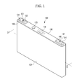
- FIG. 1 illustrates a perspective view of a rechargeable battery according to a first example embodiment
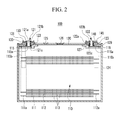
- FIG. 2 illustrates a cross-sectional view of the rechargeable battery taken along the II-II line of FIG. 1 .
- the rechargeable battery 100 may be a prismatic battery.
- the rechargeable battery 100 may include an electrode assembly 110.
- the electrode assembly 110 may include positive and negative electrodes 111 and 112 wound together with a separator 113 interposed therebetween as an insulator.
- the rechargeable battery 100 may also include a case 124 having the electrode assembly 110 therein, first and second terminals 130 and 140 electrically connected to the electrode assembly 110, and a cap plate 120 fitted to an opening 124a of the case 124.
- terminals may be electrically connected to the electrode assembly 110 and protruded to the outside of the case 124.
- the positive electrode 111 may include a current collector, e.g., a thin metal foil plate, and a positive active material.
- the positive electrode 111 may include a coated region, where the positive active material is coated, and an uncoated region 111a, where active material is not coated.
- the thin metal foil plate of the positive electrode 111 may consist entirely of aluminum or may comprise aluminum.
- the negative electrode 112 may include a current collector, e.g., a thin metal foil plate, and a negative active material.
- the negative electrode 112 may include a coated region, where the negative active material is coated, and an uncoated region 112a, where active material is not coated.
- the uncoated regions 111a and 112a may be formed at the lateral ends of the positive and the negative electrodes 111 and 112 in the longitudinal direction of the positive and the negative electrodes 111 and 112.
- the positive and the negative electrodes 111 and 112 may be spiral-wound by interposing the separator 113 therebetween as an insulator so as to form a jellyroll-shaped electrode assembly 110.
- the electrode assembly 110 may be structured such that a plurality of positive and negative electrodes 111 and 112 are alternately deposited while interposing the separator 113 therebetween.
- a first terminal 130 may be electrically connected to the positive uncoated region 111a of the electrode assembly 110 via a first lead member 115, and a second terminal 140 may be electrically connected to the negative uncoated region 112a via a second lead member 116.
- the first terminal 130 may function as a positive terminal, and the second terminal 140 may function as a negative terminal. In another implementation, the first terminal 130 may become a negative terminal, while the second terminal 140 becomes a positive terminal.
- the case 124 may be formed to have a hexahedral-shaped prismatic case having an inner space and the top opening 124a.
- the case may be formed with various shapes such as a cylinder, a pouch, etc.
- the cap plate 120 may be formed with a thin plate, and may be provided with a vent 126 having a notch capable of opening at a predetermined inner pressure.
- a plug 125 may be provided for sealing an electrolyte injection hole.
- the first and the second terminals 130 and 140 may be plate-shaped, and may be disposed parallel to the cap plate 120.
- the first terminal 130 may be fixed to the cap plate 120 by way of a first fixture 121
- the second terminal 140 may be fixed to the cap plate 120 by way of a second fixture 122.
- the fixtures 121 and 122 may be formed with or may be rivets.
- the first and second terminals 130, 140 may be secured against vibration and loosening, which may increase contact resistance.
- the nuts may be liable to release due to continuous external vibration or impact. If the nuts are released, the contact resistance between the electrode assembly and the terminals may increase so that the output of the rechargeable battery is deteriorated, and the cycle life of a battery module is reduced.
- the fixtures 121 and 122 may have pillar portions 121a and 122a inserted into the cap plate 120, top head portions 121b and 122b laterally protruding from the top ends of the pillar portions 121a and 122a, and bottom head portions 121c and 122c laterally protruding from the bottom ends of the pillar portions 121a and 122a.
- a first lead member 115 may be attached, e.g., by welding, to the bottom side of the bottom head portion 121c positioned at the bottom end of the first fixture 121.
- the first lead member 115 may entirely consist of or may comprise aluminum.
- the first fixture 121 may entirely consist of or may comprise aluminum.
- the first lead member 115 may have an upper plate 115a welded to the first fixture 121, and an attachment plate 115b protruding downward from the upper plate 115a and fixed to the positive uncoated region 111a.
- a second lead member 116 may be attached, e.g., by welding, to the bottom side of the bottom head portion 122c positioned at the bottom end of the second fixture 122.
- the second lead member 116 may entirely consist of or may comprise copper.
- the second fixture 122 may entirely consist of or may comprise copper.
- the second lead member 116 may include an upper plate 116a welded to the second fixture 122, and an attachment plate 116b protruding downward from the upper plate 116a and fixed to the negative uncoated region 112a.
- the lead members 115 and 116 may be fixed to the cap plate 120, together with the terminals 130 and 140, by way of the fixtures 121 and 122, rather than being welded to the fixtures.
- Respective terminal insulating members 123 may be installed between the cap plate 120 and the terminals 130 and 140 so as to insulate the cap plate 120 from the terminals 130, 140.
- Respective lower gaskets 127 may be disposed between the cap plate 120 and the fixtures 121 and 122 so as to insulate the cap plate 120 from the fixtures 121 and 122.
- the terminal insulating member 123 may be wider than the terminals 130 and 140, and may be tightly adhered to the top surface of the cap plate 120.
- the terminal insulating members 123 may have central through-holes for receiving the fixtures 121 and 122.
- the terminals 130 and 140 of the rechargeable battery 100 according to the present example embodiment may be fixed to the cap plate 120 by way of the rivet-shaped fixtures 121 and 122, which may endure under vibration better than a nut-coupled structure.
- FIG. 3 illustrates an exploded perspective view of the rechargeable battery according to the first example embodiment, illustrating the process of installing a fixture at a first terminal.
- the pillar-shaped fixture 121 (122) may be inserted into the terminal 130 (140) and the cap plate 120.
- the fixture 121 (122) may be pressed from the top and the bottom ends so that top head portion 121b (122b) and bottom head portion 121c (122c) are formed by deforming the pillar shaped fixture 121 (122).
- a fixture with a pre-formed bottom head portion may be inserted into a terminal and cap plate, and the top end of the fixture may be pressed from the top end so as to form a top head portion at the top end of the rivet.
- the terminals 130 and 140 may be tightly adhered to the cap plate 120 during the process of pressing the fixtures 121 and 122 so that the terminals 130 and 140 can be prevented from being released due to vibration.
- the fixtures 121 and 122 may be less susceptible to being loosened by vibration, and, hence, the contact resistance may be minimized.
- the first and the second terminals 130 and 140 may be generally formed in the shape of a rectangular plate, which has a short side with a relatively small length, and a long side with a length greater than the short sides.
- Upward protrusions 131 and 141 may be formed at both ends of the long side, respectively, and a connection member 160 (described in detail below) may be fitted between the protrusions 131 and 141.
- the first and the second terminals 130 and 140 may be formed with the same material.
- the first and second terminals 130, 140 may entirely consist of or may comprise copper.
- the rechargeable battery 100 may be a lithium battery, a lithium ion battery, etc.
- the positive current collector, the first lead member 115, and the first fixture 121 may entirely consist of or may comprise aluminum.
- the negative current collector, the second lead member 116 and the second fixture 122 may entirely consist of or may comprise copper.
- the rechargeable battery 100 may reduce or eliminate galvanic corrosion.
- galvanic corrosion may be generated between the copper first terminal 130 and the first fixture 121, which may entirely consist of or may comprise aluminum.
- galvanic corrosion may be made between the second terminal 140 and the second fixture 122, which may entirely consist of or may comprise copper.
- the galvanic corrosion between dissimilar metals may be further worsened when the potential difference is large, and the copper metal having a low ionization tendency or high ionization energy is used as the negative electrode 112, while the aluminum metal having a high ionization tendency or low ionization energy is used as the positive electrode 111.
- the possibility of galvanic corrosion is increased at the aluminum metal.
- the contact resistance between the terminals 130 and 140 and the fixtures 121 and 122 may increase. Accordingly, the output of the rechargeable battery 100 may be deteriorated.
- first and the second terminals 130 and 140 are formed with copper will now be described with reference to FIG. 2 and FIG. 3 .
- a corrosion resistance member 150 may be installed between the first terminal 130 and the first fixture 121 in order to prevent galvanic corrosion.
- the corrosion resistance member 150 may be omitted from the second terminal 140, as the materials connected at the second terminal 140 may all be the same, e.g., copper or including copper.
- the corrosion resistance member 150 may have a tube portion 151, and a head portion 153 formed at the top end of the tube portion 151 and having a cross section larger than the tube portion 151. In other words, the head portion 153 may have the shape or form of a collar with respect to the tube portion 151.
- the first terminal 130 may have a first hole 132 at a central region for receiving the tube portion 151, and a second hole 134 communicating with the first hole 132 with a diameter greater than the first hole 132 to receive the head portion 153.
- the corrosion resistance member 150 may have a hole 156, for receiving the first fixture 121, that is formed along the whole of the tube portion 151 and the head portion 153.
- the pillar-shaped first fixture 121 may be inserted into the hole 156 and the cap plate 120, and pressed so as to form the top head 121b and the bottom head 121c.
- the corrosion resistance member 150 may be formed of a material having an ionization tendency or energy that is between that of the material for the first terminal 130 and that of the material for the first fixture 121. With a difference in ionization tendency or energy between the first terminal 130 and the corrosion resistance member 150, as well as between the first fixture 121 and the corrosion resistance member 150, each being smaller than the difference in ionization tendency or energy between the corrosion resistance member 150 and the first terminal 130, the galvanic corrosion occurring at the first terminal 130 and the corrosion resistance member 150 may be reduced.
- the corrosion resistance member 150 may be formed with, e.g., nickel, stainless steel, nickel-plated copper, or a clad metal of Al-Cu, Ni-Cu, or Al-Ni, etc., having ionization tendencies between the copper and the aluminum metals.
- nickel and stainless steel are higher in ionization tendency than copper but lower than aluminum, and have excellent corrosion resistance. In other words, nickel and stainless steel are lower in ionization energy than copper but higher than aluminum, and have excellent corrosion resistance.
- the galvanic corrosion occurring between the first terminal 130 and the first fixture 121 can be reduced. Furthermore, by forming the first terminal 130 and the first fixture 121 with different materials, it is possible to form the first terminal 130 and the second terminal 140 with the same material. This may substantially simplify the electrical connection of multiple batteries in a battery module.
- FIG. 3 illustrates an enlarged view of the first terminal 130.
- the second terminal 140 can be formed using the same structures for preventing galvanic corrosion, if necessary or desired as a result of the materials used for the second terminal 140 and corresponding fixing member and electrode. Accordingly, a detailed description of such galvanic corrosion preventing structures will not be repeated for the second terminal 140.
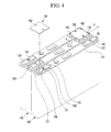
- FIG. 4 illustrates an exploded perspective view of a battery module according to a second example embodiment
- FIG. 5 illustrates a cross-sectional view of the battery module taken along the V-V line of FIG. 4 .
- the battery module 200 may include a plurality of rechargeable batteries 100.
- Respective connection members 160 may be used to electrically interconnect the rechargeable batteries 100.
- the rechargeable batteries 100 may be arranged in parallel as a stack of batteries.
- the rechargeable batteries 100 may be electrically coupled to each other in series by way of the connection members 160. In another implementation, the rechargeable batteries 100 may be electrically coupled to each other in parallel.
- a high-capacity rechargeable battery module may be formed using a plurality of rechargeable batteries 100 electrically coupled to each other in series and/or parallel.
- the rechargeable batteries 100 may have a cylindrical shape, a prismatic shape, etc.
- connection members 160 may be attached to the positive and the negative terminals by way of resistance welding.
- the positive and negative terminals are formed of a same material.
- terminals 130 and 140 may each entirely consist of or may each comprise copper. This may allow for a simple resistance welding process to be used, as it may be hard otherwise to weld dissimilar metals to each other where the positive and the negative terminals are formed with different materials.
- the connection member is formed with a material different from the positive and/or negative terminals, the melting points of the connection member and the positive and/or negative terminals may be different from each other so that it becomes hard to attach the connection member and the terminals to each other through welding.
- dissimilar metals contact each other, galvanic corrosion is more likely to occur between the dissimilar metals, and accordingly, the contact resistance between the dissimilar metals may increase.
- the first and the second terminals 130 and 140 of the adjacent rechargeable batteries 100 may be disposed next to one another.
- the connection member 160 may be welded to the first terminal 130 of one rechargeable battery 100 and the second terminal 140 of the other rechargeable battery 100.
- connection member 160 may be generally plate-shaped. In an implementation, grooves 162 are formed at both ends of the connection member 160 in order to pass the top head portions 121b and 122b of the fixtures 121 and 122.
- the connection member 160 may be fitted between the protrusions 131 and 141 of the terminals 130 and 140.
- the protrusions 131 and 141 of the respective terminals 130, 140 and the connection member 160 may be welded to each other such that welded portions 165 are formed at the contact regions between the connection member 160 and the terminals 130 and 140.
- the connection member 160 may be formed with the same material as the terminals 130 and 140.
- the connection member 160, the first terminal 130 of one battery and the second terminal 140 of the adjacent battery may each entirely consist of or may each comprise copper.
- the terminals 130 and 140 may be copper, and the connection member 160 may also be copper.
- the terminals 130 and 140 may be aluminum, and the connection member 160 may also be aluminum.
- connection member 160 in case that the terminals 130 and 140 and the connection member 160 are formed with the same material, the connection member 160 may be easily attached to those terminals by way of laser welding or resistance welding. Furthermore, when the connection member 160 is formed with copper, having a high electrical conductivity and a low resistivity, the resistance may be reduced so that the total output of the battery module 200 is enhanced. When the connection member 160 and the terminals 130 and 140 are attached to each other by way of welding, the contact resistance between the terminals 130 and 140 and the connection member 160 may be prevented from increasing from impact or external vibration.
- FIG. 6 illustrates a partial sectional view of a battery module according to a third example embodiment.
- the battery module 400 may include a plurality of rechargeable batteries 300, and respective connection members 170 electrically interconnecting the rechargeable batteries 300.
- the battery module 400 according to the present example embodiment may have the same structure as the battery module 200 according to the first example embodiment except for the structure of a first terminal 180 and the connection member 170. Descriptions of same elements as the battery module 200 will not be repeated.
- the first terminal 180 may be electrically connected to an electrode assembly 110 by way of the first fixture 121, e.g., a rivet, and fixed to the cap plate 120.
- the first fixture 121 may be electrically connected to the electrode assembly 110 via a first lead member 115.
- the first terminal 180 of one rechargeable battery 300 and an adjacent second terminal 140 of the rechargeable battery 300 neighboring thereto may be electrically connected to each other by way of the connection member 170.
- the first terminal 180 and the second terminal 140 may be formed with the same material.
- the first and second terminals 180, 140 may each entirely consist of or may each comprise copper.
- the connection member 170 may be formed of the same material as the first and second terminals 180, 140.
- the connection member 170 may be fitted between protrusions 181 of the first terminal 180 and protrusions 141 of the terminals 180 and 140, and welded to the protrusions 181 and 141 of the second terminal and 140.
- Welded portions 175 may be formed at the contact regions between the terminals 180 and 140 and the connection member 170.
- a groove 172 e.g., a recess, may be formed at the bottom side of the connection member 170 in order to receive the top head 121b of the first fixture 121.
- the top surface of the groove 172 may cover the top head 121b.
- the first terminal 180 may be plate-shaped, and protrusions 181 may be formed at both lateral ends of the first terminal 180.
- a corrosion resistance layer 185 may be formed, e.g., by a deposition process such as plating, at the contact area between the first terminal 180 and the first fixture 121.
- the deposition process may be, e.g., vapor deposition, sputtering, electroplating, electroless plating, etc.
- the corrosion resistance layer 185 may be formed with a material having an ionization tendency or energy between that of the material for the first terminal 180 and the material for the first fixture 121.
- the galvanic corrosion made at the first terminal 180 and the corrosion resistance plating layer 185 may be reduced.
- the corrosion resistance layer 185 may be formed on the first terminal 180 by way of plating. Thus, a gap may be avoided between the first terminal 180 and the corrosion resistance layer 185, and, hence, galvanic corrosion made at the first terminal 180 may be further reduced. In an implementation, the corrosion resistance layer 185 may not be formed at the contact area between the connection member 170 and the first terminal 180. Accordingly, the connection member 170 and the first terminal 180 may contact each other directly, such that the resistance between the connection member 170 and the first terminal 180 may not be increased due to the corrosion resistance layer 185.
- the first terminal 180 is formed with copper
- the first fixture 121 is formed with aluminum
- the corrosion resistance layer 185 is formed with nickel, nickel having an ionization tendency or energy between copper and aluminum.
- nickel is greater in ionization tendency than copper but smaller than aluminum and has excellent corrosion resistance, it may reduce the occurrences of corrosion in a stable manner.
- nickel is smaller in ionization energy than copper but larger than aluminum and has excellent corrosion resistance, it may reduce the occurrences of corrosion in a stable manner.
- Example embodiments have been disclosed herein, and although specific terms are employed, they are used and are to be interpreted in a generic and descriptive sense only and not for purpose of limitation. For example, features have been described herein as being formed of a particular material relative to a material of an adjacent contacting feature. However, such particular materials may be a surface coating. For example, a connection member may have a coating of copper or a copper-containing alloy, rather than being formed of copper of the copper-containing alloy. Accordingly, it will be understood by those of ordinary skill in the art that various changes in form and details may be made without departing from the scope of the present invention as set forth in the following claims.
Landscapes
- Chemical & Material Sciences (AREA)
- Chemical Kinetics & Catalysis (AREA)
- Electrochemistry (AREA)
- General Chemical & Material Sciences (AREA)
- Engineering & Computer Science (AREA)
- Manufacturing & Machinery (AREA)
- Connection Of Batteries Or Terminals (AREA)
- Battery Mounting, Suspending (AREA)
Abstract
Description
- Embodiments relate to a rechargeable battery and a battery module.
- A rechargeable battery differs from a primary battery in that it can be repeatedly charged and discharged, while the latter makes only the irreversible conversion of chemical to electrical energy. The low-capacity rechargeable battery is used as the power supply for small electronic devices, such as cellular phones, notebook computers and camcorders, while the high-capacity rechargeable battery is used as the power supply for driving motors in hybrid vehicles and the like.
- A high-power rechargeable battery using a non-aqueous electrolyte with a high energy density has been recently developed. For example, the high-power rechargeable battery is constructed with a high-capacity rechargeable battery having a plurality of rechargeable cells coupled to each other in series such that it can be used as the power supply for driving motors in electric vehicles requiring high power.
- The above information disclosed in this Background section is only for enhancement of understanding of the related art and may contain information that does not form the prior art that is already known in this country to a person of ordinary skill in the art.
- Embodiments are therefore directed to a rechargeable battery and a battery module, which substantially overcome one or more of the problems due to the limitations and disadvantages of the related art.
- It is therefore a feature of an embodiment to provide a rechargeable battery with an improved terminal structure, and a battery module including the same.
- It is therefore another feature of an embodiment to provide a rechargeable battery that includes provisions for preventing galvanic corrosion, and a battery module including the same.
- At least one of the above and other features may be realized by providing a battery, including a battery case, an electrode assembly in the battery case, the electrode assembly including a first electrode, a first terminal exposed to an exterior of the battery case, the first terminal being electrically connected to the first electrode, a first fixing member mechanically coupling the first terminal to the battery, the first fixing member forming at least part of an electrical path from the first terminal to the first electrode, and a corrosion resistance member providing an electrical path from the first terminal to the first fixing member and being in direct contact with each of the first terminal and the first fixing member.
- The corrosion resistance member may prevent the first terminal from directly contacting the first fixing member.
- The first terminal may have a surface formed of a metal having a first ionization tendency or energy, the first fixing member may have a surface formed of a metal having a second ionization tendency or energy, and the corrosion resistance member may have a surface formed of a metal having a third ionization tendency or energy that is between the first ionization tendency or energy and the second ionization tendency or energy.
- The first terminal may serve as the positive terminal.
- The first terminal may serve as the cathode terminal during discharge of the battery.
- The metal forming the surface of the first terminal may be copper, and the metal forming the surface of the first fixing member may be aluminum.
- The first electrode may include aluminum, and the first fixing member may electrically contact the first electrode.
- The metal forming the surface of the corrosion resistance member may be nickel, stainless steel, nickel-plated copper, or a clad metal of Al-Cu, Ni-Cu, or Al-Ni.
- The first terminal may serve as the negative terminal.
- The first terminal may serve as the anode terminal during discharge of the battery.
- The metal forming the surface of the first terminal may be aluminum, and the metal forming the surface of the first fixing member may be copper.
- The first electrode may include copper, and the first fixing member may electrically contact the first electrode.
- The metal forming the surface of the corrosion resistance member may be nickel, stainless steel, nickel-plated copper, or a clad metal of Al-Cu, Ni-Cu, or Al-Ni.
- The corrosion resistance member may be separate from the first terminal and the first fixing member.
- The corrosion resistance member may be integral with the first terminal.
- The corrosion resistance member may be a layer deposited on the first terminal.
- The corrosion resistance member may be a plating layer on the first terminal.
- The electrode assembly may further include a second electrode and a separator, the separator separating the first electrode from the second electrode.
- The first fixing member may be a rivet.
- At least one of the above and other features may also be realized by providing a battery module, including a first battery, and a second battery electrically connected to the first battery, each of the first and second batteries including a battery case, an electrode assembly in the battery case, the electrode assembly including a first electrode, a first terminal exposed to an exterior of the battery case, the first terminal being electrically connected to the first electrode, a first fixing member mechanically coupling the first terminal to the battery, the first fixing member forming at least part of an electrical path from the first terminal to the first electrode, and a corrosion resistance member providing an electrical path from the first terminal to the first fixing member and being in direct contact with each of the first terminal and the first fixing member.
- The corrosion resistance member may prevent the first terminal from directly contacting the first fixing member.
- The first battery and the second battery may be electrically connected to one another in series, the first terminals of the respective first and second batteries serving as positive terminals, and the positive terminal of the first battery may be electrically connected to a negative terminal of the second battery by a connection member that is welded to each of the positive terminal of the first battery and the negative terminal of the second battery. Outer surfaces of the positive terminal of the first battery, the negative terminal of the second battery, and the connection member may each be formed of a same metal.
- The first fixing member may be a rivet, the rivet having an outer surface formed of a metal different from an outer surface of the positive terminal.
- The above and other features and advantages will become more apparent to those of ordinary skill in the art by describing in detail example embodiments with reference to the attached drawings, in which:
-
FIG. 1 illustrates a perspective view of a rechargeable battery according to a first example embodiment, -
FIG. 2 illustrates a cross-sectional view of the rechargeable battery taken along the II-II line ofFIG. 1 , -
FIG. 3 illustrates an exploded perspective view of the rechargeable battery according to the first example embodiment, illustrating the process of installing a fixture at a first terminal, -
FIG. 4 illustrates an exploded perspective view of a battery module according to a second example embodiment, -
FIG. 5 illustrates a cross-sectional view of the battery module taken along the V-V line ofFIG. 4 , and -
FIG. 6 illustrates a partial sectional view of a battery module according to a third example embodiment. - Example embodiments will now be described more fully hereinafter with reference to the accompanying drawings, however, they may be embodied in different forms and should not be construed as limited to the embodiments set forth herein. Rather, these embodiments are provided so that this disclosure will be thorough and complete, and will fully convey the scope of the invention to those skilled in the art.
- In the drawing figures, dimensions may be exaggerated for clarity of illustration. It will be understood that when an element is referred to as being "on" another element, it can be directly on the other element, or one or more intervening elements may also be present. It will also be understood that when an element is referred to as being "under" another element, it can be directly under, or one or more intervening elements may also be present. It will also be understood that when an element is referred to as being "between" two elements, it can be the only element between the two elements, or one or more intervening elements may also be present. Like reference numerals refer to like elements throughout.
- As used herein, the term "anode" refers to the electrode at which oxidation occurs. As used herein, the term "cathode" refers to the electrode at which reduction occurs. The terminal that is coupled to the anode ("anode terminal") is the negative terminal (-) of the electrochemical cell (or unit battery) while the electrochemical cell is discharging. The anode terminal provides electrons to the load circuit during discharge of the electrochemical cell. The terminal that is coupled to the cathode is the positive terminal (+) of the electrochemical cell while the electrochemical cell is discharging. The cathode terminal receives electrons from the load circuit during discharge of the electrochemical cell. While the battery is being charged, energy is input to the battery to regenerate the electrochemical potential of the battery. Thus, the oxidation and reduction locations interchange (or swap), such that the positive terminal of the electrochemical cell is the anode while the battery is being charged and the negative terminal of the electrochemical cell is the cathode while the battery is being charged.
-
FIG. 1 illustrates a perspective view of a rechargeable battery according to a first example embodiment, andFIG. 2 illustrates a cross-sectional view of the rechargeable battery taken along the II-II line ofFIG. 1 . - Referring to
FIG. 1 andFIG. 2 , therechargeable battery 100 may be a prismatic battery. Therechargeable battery 100 may include anelectrode assembly 110. Theelectrode assembly 110 may include positive andnegative electrodes separator 113 interposed therebetween as an insulator. Therechargeable battery 100 may also include acase 124 having theelectrode assembly 110 therein, first andsecond terminals electrode assembly 110, and acap plate 120 fitted to an opening 124a of thecase 124. As described in greater detail below, terminals may be electrically connected to theelectrode assembly 110 and protruded to the outside of thecase 124. - The
positive electrode 111 may include a current collector, e.g., a thin metal foil plate, and a positive active material. Thepositive electrode 111 may include a coated region, where the positive active material is coated, and anuncoated region 111a, where active material is not coated. The thin metal foil plate of thepositive electrode 111 may consist entirely of aluminum or may comprise aluminum. Thenegative electrode 112 may include a current collector, e.g., a thin metal foil plate, and a negative active material. Thenegative electrode 112 may include a coated region, where the negative active material is coated, and anuncoated region 112a, where active material is not coated. Theuncoated regions negative electrodes negative electrodes negative electrodes separator 113 therebetween as an insulator so as to form a jellyroll-shapedelectrode assembly 110. - In another implementation, the
electrode assembly 110 may be structured such that a plurality of positive andnegative electrodes separator 113 therebetween. - A
first terminal 130 may be electrically connected to the positiveuncoated region 111a of theelectrode assembly 110 via afirst lead member 115, and asecond terminal 140 may be electrically connected to the negativeuncoated region 112a via asecond lead member 116. - The
first terminal 130 may function as a positive terminal, and thesecond terminal 140 may function as a negative terminal. In another implementation, thefirst terminal 130 may become a negative terminal, while thesecond terminal 140 becomes a positive terminal. - The
case 124 may be formed to have a hexahedral-shaped prismatic case having an inner space and the top opening 124a. In another implementation, the case may be formed with various shapes such as a cylinder, a pouch, etc. - The
cap plate 120 may be formed with a thin plate, and may be provided with avent 126 having a notch capable of opening at a predetermined inner pressure. Aplug 125 may be provided for sealing an electrolyte injection hole. - The first and the
second terminals cap plate 120. Thefirst terminal 130 may be fixed to thecap plate 120 by way of afirst fixture 121, and thesecond terminal 140 may be fixed to thecap plate 120 by way of asecond fixture 122. In an implementation, thefixtures fixtures second terminals - The
fixtures pillar portions cap plate 120,top head portions pillar portions bottom head portions pillar portions - A
first lead member 115 may be attached, e.g., by welding, to the bottom side of thebottom head portion 121c positioned at the bottom end of thefirst fixture 121. Thefirst lead member 115 may entirely consist of or may comprise aluminum. Similarly, thefirst fixture 121 may entirely consist of or may comprise aluminum. Thefirst lead member 115 may have anupper plate 115a welded to thefirst fixture 121, and anattachment plate 115b protruding downward from theupper plate 115a and fixed to the positiveuncoated region 111a. - A
second lead member 116 may be attached, e.g., by welding, to the bottom side of thebottom head portion 122c positioned at the bottom end of thesecond fixture 122. Thesecond lead member 116 may entirely consist of or may comprise copper. Similarly, thesecond fixture 122 may entirely consist of or may comprise copper. Thesecond lead member 116 may include anupper plate 116a welded to thesecond fixture 122, and anattachment plate 116b protruding downward from theupper plate 116a and fixed to the negativeuncoated region 112a. - In another implementation, the
lead members cap plate 120, together with theterminals fixtures - Respective terminal insulating
members 123 may be installed between thecap plate 120 and theterminals cap plate 120 from theterminals lower gaskets 127 may be disposed between thecap plate 120 and thefixtures cap plate 120 from thefixtures - The terminal insulating
member 123 may be wider than theterminals cap plate 120. The terminal insulatingmembers 123 may have central through-holes for receiving thefixtures - The
terminals rechargeable battery 100 according to the present example embodiment may be fixed to thecap plate 120 by way of the rivet-shapedfixtures -
FIG. 3 illustrates an exploded perspective view of the rechargeable battery according to the first example embodiment, illustrating the process of installing a fixture at a first terminal. - An example of installation of the first fixture 121 (and the
second fixture 122, which may be installed in substantially the same manner) will now be described with reference toFIG. 2 andFIG. 3 . As shown inFIG. 3 , the pillar-shaped fixture 121 (122) may be inserted into the terminal 130 (140) and thecap plate 120. In this state, the fixture 121 (122) may be pressed from the top and the bottom ends so thattop head portion 121b (122b) andbottom head portion 121c (122c) are formed by deforming the pillar shaped fixture 121 (122). In another implementation, a fixture with a pre-formed bottom head portion may be inserted into a terminal and cap plate, and the top end of the fixture may be pressed from the top end so as to form a top head portion at the top end of the rivet. - The
terminals cap plate 120 during the process of pressing thefixtures terminals - It is most important with the
rechargeable battery 100 to reduce the contact resistance. Excessively high contact resistance may degrade the output of therechargeable battery 100, and may generate resistance heating from high current flow so that the temperature of therechargeable battery 100 is elevated. When the temperature of therechargeable battery 100 is elevated, an abnormal reaction may occur internally, and, accordingly, the cycle life of therechargeable battery 100 may be reduced. However, with the present example embodiment, thefixtures - As shown in
FIG. 1 , the first and thesecond terminals -
Upward protrusions protrusions - The first and the
second terminals second terminals rechargeable battery 100 may be a lithium battery, a lithium ion battery, etc. In an embodiment, the positive current collector, thefirst lead member 115, and thefirst fixture 121 may entirely consist of or may comprise aluminum. The negative current collector, thesecond lead member 116 and thesecond fixture 122 may entirely consist of or may comprise copper. - As described in detail below, the
rechargeable battery 100 according to an embodiment may reduce or eliminate galvanic corrosion. In this regard, where the first and thesecond terminals first terminal 130 and thefirst fixture 121, which may entirely consist of or may comprise aluminum. Meanwhile, if the first and thesecond terminals second terminal 140 and thesecond fixture 122, which may entirely consist of or may comprise copper. Moreover, the galvanic corrosion between dissimilar metals may be further worsened when the potential difference is large, and the copper metal having a low ionization tendency or high ionization energy is used as thenegative electrode 112, while the aluminum metal having a high ionization tendency or low ionization energy is used as thepositive electrode 111. As copper and aluminum are largely differentiated in ionization tendency and energy from each other, the possibility of galvanic corrosion is increased at the aluminum metal. - If galvanic corrosion is made between the
terminals fixtures terminals fixtures rechargeable battery 100 may be deteriorated. - In accordance with the present example embodiment, the case where the first and the
second terminals FIG. 2 andFIG. 3 . - A
corrosion resistance member 150 may be installed between thefirst terminal 130 and thefirst fixture 121 in order to prevent galvanic corrosion. In an implementation, thecorrosion resistance member 150 may be omitted from thesecond terminal 140, as the materials connected at thesecond terminal 140 may all be the same, e.g., copper or including copper. Thecorrosion resistance member 150 may have atube portion 151, and ahead portion 153 formed at the top end of thetube portion 151 and having a cross section larger than thetube portion 151. In other words, thehead portion 153 may have the shape or form of a collar with respect to thetube portion 151. Thefirst terminal 130 may have afirst hole 132 at a central region for receiving thetube portion 151, and asecond hole 134 communicating with thefirst hole 132 with a diameter greater than thefirst hole 132 to receive thehead portion 153. - The
corrosion resistance member 150 may have ahole 156, for receiving thefirst fixture 121, that is formed along the whole of thetube portion 151 and thehead portion 153. - The pillar-shaped
first fixture 121 may be inserted into thehole 156 and thecap plate 120, and pressed so as to form thetop head 121b and thebottom head 121c. - The
corrosion resistance member 150 may be formed of a material having an ionization tendency or energy that is between that of the material for thefirst terminal 130 and that of the material for thefirst fixture 121. With a difference in ionization tendency or energy between thefirst terminal 130 and thecorrosion resistance member 150, as well as between thefirst fixture 121 and thecorrosion resistance member 150, each being smaller than the difference in ionization tendency or energy between thecorrosion resistance member 150 and thefirst terminal 130, the galvanic corrosion occurring at thefirst terminal 130 and thecorrosion resistance member 150 may be reduced. - In an implementation, taking as an example a case where the
first terminal 130 is formed with copper and thefirst fixture 121 is formed with aluminum, thecorrosion resistance member 150 may be formed with, e.g., nickel, stainless steel, nickel-plated copper, or a clad metal of Al-Cu, Ni-Cu, or Al-Ni, etc., having ionization tendencies between the copper and the aluminum metals. As particular examples, nickel and stainless steel are higher in ionization tendency than copper but lower than aluminum, and have excellent corrosion resistance. In other words, nickel and stainless steel are lower in ionization energy than copper but higher than aluminum, and have excellent corrosion resistance. - As described above, with the present example embodiment, even in case the
first terminal 130 and thefirst fixture 121 are formed with different materials, the galvanic corrosion occurring between thefirst terminal 130 and thefirst fixture 121 can be reduced. Furthermore, by forming thefirst terminal 130 and thefirst fixture 121 with different materials, it is possible to form thefirst terminal 130 and thesecond terminal 140 with the same material. This may substantially simplify the electrical connection of multiple batteries in a battery module. -
FIG. 3 illustrates an enlarged view of thefirst terminal 130. It will be appreciated that thesecond terminal 140 can be formed using the same structures for preventing galvanic corrosion, if necessary or desired as a result of the materials used for thesecond terminal 140 and corresponding fixing member and electrode. Accordingly, a detailed description of such galvanic corrosion preventing structures will not be repeated for thesecond terminal 140. -
FIG. 4 illustrates an exploded perspective view of a battery module according to a second example embodiment, andFIG. 5 illustrates a cross-sectional view of the battery module taken along the V-V line ofFIG. 4 . - Referring to
FIG. 5 , the battery module 200 according to the present example embodiment may include a plurality ofrechargeable batteries 100.Respective connection members 160 may be used to electrically interconnect therechargeable batteries 100. Therechargeable batteries 100 may be arranged in parallel as a stack of batteries. Therechargeable batteries 100 may be electrically coupled to each other in series by way of theconnection members 160. In another implementation, therechargeable batteries 100 may be electrically coupled to each other in parallel. - A high-capacity rechargeable battery module may be formed using a plurality of
rechargeable batteries 100 electrically coupled to each other in series and/or parallel. Therechargeable batteries 100 may have a cylindrical shape, a prismatic shape, etc. - In the battery module, the
connection members 160 may be attached to the positive and the negative terminals by way of resistance welding. Preferably, the positive and negative terminals are formed of a same material. For example,terminals - In the battery module 200 according to the present example embodiment, the first and the
second terminals rechargeable batteries 100 may be disposed next to one another. Thus, theconnection member 160 may be welded to thefirst terminal 130 of onerechargeable battery 100 and thesecond terminal 140 of the otherrechargeable battery 100. - The
connection member 160 may be generally plate-shaped. In an implementation,grooves 162 are formed at both ends of theconnection member 160 in order to pass thetop head portions fixtures connection member 160 may be fitted between theprotrusions terminals protrusions respective terminals connection member 160 may be welded to each other such that weldedportions 165 are formed at the contact regions between theconnection member 160 and theterminals connection member 160 may be formed with the same material as theterminals connection member 160, thefirst terminal 130 of one battery and thesecond terminal 140 of the adjacent battery may each entirely consist of or may each comprise copper. In an implementation, theterminals connection member 160 may also be copper. In another implementation, theterminals connection member 160 may also be aluminum. - In the present example embodiment, in case that the
terminals connection member 160 are formed with the same material, theconnection member 160 may be easily attached to those terminals by way of laser welding or resistance welding. Furthermore, when theconnection member 160 is formed with copper, having a high electrical conductivity and a low resistivity, the resistance may be reduced so that the total output of the battery module 200 is enhanced. When theconnection member 160 and theterminals terminals connection member 160 may be prevented from increasing from impact or external vibration. -
FIG. 6 illustrates a partial sectional view of a battery module according to a third example embodiment. - The battery module 400 according to the present example embodiment may include a plurality of rechargeable batteries 300, and
respective connection members 170 electrically interconnecting the rechargeable batteries 300. - The battery module 400 according to the present example embodiment may have the same structure as the battery module 200 according to the first example embodiment except for the structure of a
first terminal 180 and theconnection member 170. Descriptions of same elements as the battery module 200 will not be repeated. - The
first terminal 180 may be electrically connected to anelectrode assembly 110 by way of thefirst fixture 121, e.g., a rivet, and fixed to thecap plate 120. Thefirst fixture 121 may be electrically connected to theelectrode assembly 110 via afirst lead member 115. - As with the first example embodiment, the
first terminal 180 of one rechargeable battery 300 and an adjacentsecond terminal 140 of the rechargeable battery 300 neighboring thereto may be electrically connected to each other by way of theconnection member 170. Thefirst terminal 180 and thesecond terminal 140 may be formed with the same material. For example, the first andsecond terminals connection member 170 may be formed of the same material as the first andsecond terminals connection member 170 may be fitted betweenprotrusions 181 of thefirst terminal 180 andprotrusions 141 of theterminals protrusions portions 175 may be formed at the contact regions between theterminals connection member 170. Agroove 172, e.g., a recess, may be formed at the bottom side of theconnection member 170 in order to receive thetop head 121b of thefirst fixture 121. The top surface of thegroove 172 may cover thetop head 121b. - The
first terminal 180 may be plate-shaped, andprotrusions 181 may be formed at both lateral ends of thefirst terminal 180. Acorrosion resistance layer 185 may be formed, e.g., by a deposition process such as plating, at the contact area between thefirst terminal 180 and thefirst fixture 121. The deposition process may be, e.g., vapor deposition, sputtering, electroplating, electroless plating, etc. Thecorrosion resistance layer 185 may be formed with a material having an ionization tendency or energy between that of the material for thefirst terminal 180 and the material for thefirst fixture 121. - With a difference in ionization tendency or energy between the
corrosion resistance layer 185 and thefirst terminal 180, and the difference in ionization tendency or energy between thecorrosion resistance layer 185 and thefirst fixture 121, each being smaller than the difference in ionization tendency or energy between thefirst terminal 180 and thefirst fixture 121, the galvanic corrosion made at thefirst terminal 180 and the corrosionresistance plating layer 185 may be reduced. - In an implementation, the
corrosion resistance layer 185 may be formed on thefirst terminal 180 by way of plating. Thus, a gap may be avoided between thefirst terminal 180 and thecorrosion resistance layer 185, and, hence, galvanic corrosion made at thefirst terminal 180 may be further reduced. In an implementation, thecorrosion resistance layer 185 may not be formed at the contact area between theconnection member 170 and thefirst terminal 180. Accordingly, theconnection member 170 and thefirst terminal 180 may contact each other directly, such that the resistance between theconnection member 170 and thefirst terminal 180 may not be increased due to thecorrosion resistance layer 185. - In a specific example according to the present embodiment, the
first terminal 180 is formed with copper, thefirst fixture 121 is formed with aluminum, and thecorrosion resistance layer 185 is formed with nickel, nickel having an ionization tendency or energy between copper and aluminum. As nickel is greater in ionization tendency than copper but smaller than aluminum and has excellent corrosion resistance, it may reduce the occurrences of corrosion in a stable manner. In other words, as nickel is smaller in ionization energy than copper but larger than aluminum and has excellent corrosion resistance, it may reduce the occurrences of corrosion in a stable manner. - Example embodiments have been disclosed herein, and although specific terms are employed, they are used and are to be interpreted in a generic and descriptive sense only and not for purpose of limitation. For example, features have been described herein as being formed of a particular material relative to a material of an adjacent contacting feature. However, such particular materials may be a surface coating. For example, a connection member may have a coating of copper or a copper-containing alloy, rather than being formed of copper of the copper-containing alloy. Accordingly, it will be understood by those of ordinary skill in the art that various changes in form and details may be made without departing from the scope of the present invention as set forth in the following claims.
Claims (15)
- A battery, comprising:a battery case (124);an electrode assembly (110) in the battery case (124), the electrode assembly (110) including a first electrode (111);a first terminal (130) exposed to an exterior of the battery case (124), the first terminal (130) being electrically connected to the first electrode (111);a first fixing member (121) mechanically coupling the first terminal (130) to the battery, the first fixing member (121) forming at least part of an electrical path from the first terminal (130) to the first electrode (111), anda corrosion resistance member (150) providing an electrical path from the first terminal (130) to the first fixing member (121) and being in direct contact with each of the first terminal (130) and the first fixing member (121).
- The battery as claimed in claim 1, wherein the corrosion resistance member (150) prevents the first terminal (130) from directly contacting the first fixing member (121).
- The battery as claimed in claim 1 or 2, wherein:the first terminal (130) has a surface formed of a metal having a first ionization energy,the first fixing member (121) has a surface formed of a metal having a second ionization energy, andthe corrosion resistance member (150) has a surface formed of a metal having a third ionization energy that is between the first ionization energy and the second ionization energy.
- The battery as claimed in claim 3, wherein the first terminal (130):serves as the positive terminal during charge, orserves as the negative terminal during charge.
- The battery as claimed in claim 4, wherein:with respect to the first alternative of claim 4, the metal forming the surface of the first terminal (130) is copper, and the metal forming the surface of the first fixing member (121) is aluminum; orwith respect to the second alternative of claim 4, the metal forming the surface of the first terminal (130) is aluminum, and the metal forming the surface of the first fixing member (121) is copper.
- The battery as claimed in claim 5, wherein:with respect to the first alternative of claim 5, the first electrode (111) includes aluminum, and the first fixing member (121) electrically contacts the first electrode (111), orwith respect to the second alternative of claim 5, the first electrode (111) includes copper, and the first fixing member (121) electrically contacts the first electrode (111).
- The battery as claimed in one of the previous claims, wherein the metal forming the surface of the corrosion resistance member (150) is nickel, stainless steel, nickel-plated copper, or a clad metal of Al-Cu, Ni-Cu, or Al-Ni.
- The battery as claimed in one of the previous claims, wherein the corrosion resistance member (150) is a separate element with respect to the first terminal (130) and the first fixing member (121), or wherein the corrosion resistance member (185) is integrally formed with the first terminal (180).
- The battery as claimed in claim 8, 2nd alternative, wherein the corrosion resistance member (185) is a layer deposited on the first terminal (180), particularly a plating layer on the first terminal (180).
- The battery as claimed in one of the previous claims, wherein the first fixing member (121) is a rivet.
- A battery module, comprising:a first battery; anda second battery electrically connected to the first battery, each of the first and second batteries including:a battery case (124),an electrode assembly (110) in the battery case (124), the electrode assembly (110) including a first electrode (111),a first terminal (130) exposed to an exterior of the battery case (124), the first terminal (130) being electrically connected to the first electrode (111),a first fixing member (121) mechanically coupling the first terminal (130) to the battery, the first fixing member (121) forming at least part of an electrical path from the first terminal (130) to the first electrode (111), anda corrosion resistance member (150) providing an electrical path from the first terminal (130) to the first fixing member (121) and being in direct contact with each of the first terminal (130) and the first fixing member (121).
- The battery module as claimed in claim 11, wherein the corrosion resistance member (150) prevents the first terminal (130) from directly contacting the first fixing member (121).
- The battery module as claimed in claim 11 or 12, wherein:the first battery and the second battery are electrically connected to one another in series, the first terminals (130) of the respective first and second batteries serving as positive terminals, andthe positive terminal of the first battery is electrically connected to a negative terminal of the second battery by a connection member (160) that is welded to each of the positive terminal of the first battery and the negative terminal of the second battery.
- The battery module as claimed in claim 13, wherein outer surfaces of the positive terminal of the first battery, the negative terminal of the second battery, and the connection member (160) are each formed of a same metal.
- The battery module as claimed in claim 14, wherein the first fixing member (121) is a rivet, the rivet having an outer surface formed of a metal different from an outer surface of the positive terminal.
Applications Claiming Priority (2)
| Application Number | Priority Date | Filing Date | Title |
|---|---|---|---|
| US27251109P | 2009-10-01 | 2009-10-01 | |
| US12/654,990 US8263255B2 (en) | 2009-10-01 | 2010-01-12 | Rechargeable battery and battery module |
Publications (2)
| Publication Number | Publication Date |
|---|---|
| EP2312675A1 true EP2312675A1 (en) | 2011-04-20 |
| EP2312675B1 EP2312675B1 (en) | 2012-09-19 |
Family
ID=43086237
Family Applications (1)
| Application Number | Title | Priority Date | Filing Date |
|---|---|---|---|
| EP10177774A Active EP2312675B1 (en) | 2009-10-01 | 2010-09-21 | Electrically conductive connection between electrode and terminal |
Country Status (5)
| Country | Link |
|---|---|
| US (1) | US8263255B2 (en) |
| EP (1) | EP2312675B1 (en) |
| JP (1) | JP5606851B2 (en) |
| KR (1) | KR101125640B1 (en) |
| CN (1) | CN102034954B (en) |
Cited By (7)
| Publication number | Priority date | Publication date | Assignee | Title |
|---|---|---|---|---|
| EP2624329A1 (en) * | 2012-02-01 | 2013-08-07 | Samsung SDI Co., Ltd. | Rechargeable battery |
| EP2752921A4 (en) * | 2011-08-29 | 2015-03-04 | Shenzhen Byd Auto R & D Co Ltd | BATTERY TERMINAL, BATTERY COVER PLATE ASSEMBLY, UNIT BATTERY, AND BATTERY UNIT |
| EP2887429A1 (en) * | 2013-12-23 | 2015-06-24 | Samsung SDI Co., Ltd. | Secondary battery and secondary battery module |
| EP3062370A4 (en) * | 2013-10-25 | 2017-04-19 | Hitachi Automotive Systems, Ltd. | Rectangular secondary battery |
| EP3511994A1 (en) * | 2018-01-11 | 2019-07-17 | Contemporary Amperex Technology Co., Limited | Battery cap assembly, secondary battery and battery module |
| EP3511995A1 (en) * | 2018-01-11 | 2019-07-17 | Contemporary Amperex Technology Co., Limited | Battery cap assembly, secondary battery and battery module |
| EP3671889A1 (en) * | 2010-12-10 | 2020-06-24 | GS Yuasa International Ltd. | Storage element |
Families Citing this family (45)
| Publication number | Priority date | Publication date | Assignee | Title |
|---|---|---|---|---|
| US8673479B2 (en) * | 2010-03-30 | 2014-03-18 | Samsung Sdi Co., Ltd. | Secondary battery and a secondary battery module |
| KR101135510B1 (en) * | 2010-05-20 | 2012-04-13 | 에스비리모티브 주식회사 | Rechargeable battery and battery module |
| JP5558569B2 (en) | 2010-07-21 | 2014-07-23 | 株式会社東芝 | Battery and battery pack |
| KR101244739B1 (en) * | 2011-05-09 | 2013-03-18 | 로베르트 보쉬 게엠베하 | Battery module |
| WO2012169055A1 (en) * | 2011-06-10 | 2012-12-13 | 日立ビークルエナジー株式会社 | Secondary battery |
| KR101265214B1 (en) * | 2011-06-22 | 2013-05-27 | 로베르트 보쉬 게엠베하 | Rechargeable battery and method manufacturing of the same |
| CN103125035B (en) * | 2011-06-30 | 2016-01-27 | 株式会社Lg化学 | Electrode terminal for secondary battery and secondary battery including same |
| US9236596B2 (en) * | 2011-06-30 | 2016-01-12 | Samsung Sdi Co., Ltd. | Rechargeable battery |
| KR101294931B1 (en) | 2011-08-04 | 2013-08-08 | 히타치 긴조쿠 가부시키가이샤 | Negative-electrode terminal for cell |
| KR101683213B1 (en) * | 2011-11-02 | 2016-12-07 | 삼성에스디아이 주식회사 | Rechargeable battery |
| KR101666870B1 (en) * | 2012-03-20 | 2016-10-17 | 삼성에스디아이 주식회사 | Rechargeable battery including resistance member |
| WO2014076817A1 (en) * | 2012-11-16 | 2014-05-22 | 日立ビークルエナジー株式会社 | Unit cell and battery |
| KR20140090902A (en) * | 2013-01-10 | 2014-07-18 | 삼성에스디아이 주식회사 | Secondary bttery and secondary bttery module |
| KR101688481B1 (en) * | 2013-04-08 | 2016-12-21 | 삼성에스디아이 주식회사 | Battery unit and battery module using the same |
| CN203218359U (en) * | 2013-04-19 | 2013-09-25 | 宁德新能源科技有限公司 | Pressure relief valve and power battery top cover |
| US9570719B2 (en) * | 2013-05-22 | 2017-02-14 | Samsung Sdi Co., Ltd. | Secondary battery |
| JP6070490B2 (en) * | 2013-09-11 | 2017-02-01 | 日立金属株式会社 | Battery terminal and battery terminal manufacturing method |
| KR101711988B1 (en) * | 2013-09-12 | 2017-03-03 | 삼성에스디아이 주식회사 | Rechargeable battery |
| KR101724013B1 (en) * | 2013-09-24 | 2017-04-06 | 삼성에스디아이 주식회사 | Rechargeable battery |
| JP6269383B2 (en) | 2013-09-24 | 2018-01-31 | 株式会社Gsユアサ | Power storage device |
| JP6394749B2 (en) * | 2013-09-24 | 2018-09-26 | 株式会社Gsユアサ | Power storage device |
| JP5943396B2 (en) | 2013-09-25 | 2016-07-05 | 株式会社日立金属ネオマテリアル | Battery terminal, battery terminal manufacturing method and battery |
| WO2015125487A1 (en) | 2014-02-21 | 2015-08-27 | 株式会社リチウムエナジージャパン | Electricity storage element and electricity storage element production method |
| KR102226514B1 (en) * | 2014-06-17 | 2021-03-11 | 삼성에스디아이 주식회사 | Secondary battery |
| US9887409B2 (en) * | 2014-09-30 | 2018-02-06 | Johnson Controls Technology Company | Battery module bus bar connection assembly |
| US20160336578A1 (en) * | 2015-05-11 | 2016-11-17 | Johnson Controls Technology Company | Features for preventing short circuit in a battery module |
| JP6014808B1 (en) * | 2015-08-17 | 2016-10-26 | 日立金属株式会社 | Battery terminal and battery terminal manufacturing method |
| WO2017181178A1 (en) * | 2016-04-15 | 2017-10-19 | Ems Engineered Material Solutions, Llc | Clad material for electrical terminal connectors and the method of making the same |
| CN114843668B (en) | 2017-08-30 | 2023-12-12 | 宁德时代新能源科技股份有限公司 | Top cap subassembly, secondary cell and battery module of secondary cell |
| JP2019075214A (en) * | 2017-10-12 | 2019-05-16 | 株式会社Gsユアサ | Power storage element and manufacturing method of power storage element |
| JP7041487B2 (en) * | 2017-10-17 | 2022-03-24 | 株式会社Gsユアサ | Power storage element |
| JP7029924B2 (en) * | 2017-10-17 | 2022-03-04 | 株式会社Gsユアサ | Power storage element and power storage module |
| JP7064695B2 (en) * | 2017-12-15 | 2022-05-11 | トヨタ自動車株式会社 | Sealed battery, assembled battery, manufacturing method of sealed battery and manufacturing method of assembled battery |
| JP7368080B2 (en) * | 2018-08-31 | 2023-10-24 | 三洋電機株式会社 | secondary battery |
| JP7169521B2 (en) * | 2019-02-28 | 2022-11-11 | トヨタ自動車株式会社 | Sealed batteries and assembled batteries |
| JP7256780B2 (en) | 2020-09-17 | 2023-04-12 | プライムプラネットエナジー&ソリューションズ株式会社 | SECONDARY BATTERY TERMINAL AND METHOD FOR MANUFACTURING SECONDARY BATTERY TERMINAL |
| JP7252926B2 (en) * | 2020-09-17 | 2023-04-05 | プライムプラネットエナジー&ソリューションズ株式会社 | SECONDARY BATTERY TERMINAL AND SECONDARY BATTERY INCLUDING THE TERMINAL |
| JP7402202B2 (en) | 2021-07-15 | 2023-12-20 | プライムプラネットエナジー&ソリューションズ株式会社 | Terminal components and terminal component manufacturing method |
| CN115775940B (en) * | 2021-09-08 | 2024-10-25 | 中创新航科技集团股份有限公司 | Battery cover plate assembly, battery preparation method and battery |
| US11929522B2 (en) | 2021-09-24 | 2024-03-12 | Apple Inc. | Battery cells with tabs at right angles |
| US11870100B2 (en) | 2021-09-24 | 2024-01-09 | Apple Inc. | Battery cells with tabs at right angles |
| US11942661B2 (en) * | 2021-09-24 | 2024-03-26 | Apple Inc. | Battery cells with tabs at right angles |
| CN114142151A (en) * | 2021-12-31 | 2022-03-04 | 中创新航科技股份有限公司 | Battery device |
| KR20240035149A (en) * | 2022-09-08 | 2024-03-15 | 주식회사 엘지에너지솔루션 | Bus Bar Having Clad Member |
| KR20250026055A (en) * | 2023-08-16 | 2025-02-25 | 주식회사 엘지에너지솔루션 | Battery module |
Citations (2)
| Publication number | Priority date | Publication date | Assignee | Title |
|---|---|---|---|---|
| JPS63158739A (en) * | 1986-12-22 | 1988-07-01 | Matsushita Electric Ind Co Ltd | Organic electrolyte cell |
| WO2006085914A2 (en) * | 2004-06-09 | 2006-08-17 | The Gillette Company | Alkaline cell with flat housing and nickel oxyhydroxide cathode |
Family Cites Families (15)
| Publication number | Priority date | Publication date | Assignee | Title |
|---|---|---|---|---|
| US4792503A (en) * | 1988-01-25 | 1988-12-20 | Honeywell Inc. | Multi-functional hermetic seal for non-aqueous electrochemical cells |
| JP2000113865A (en) | 1998-10-02 | 2000-04-21 | At Battery:Kk | Rechargeable battery |
| JP2001357834A (en) * | 2000-06-16 | 2001-12-26 | Japan Storage Battery Co Ltd | Battery |
| US6696199B2 (en) * | 2002-01-30 | 2004-02-24 | Japan Storage Battery Co., Ltd. | Battery |
| JP3937140B2 (en) * | 2002-01-30 | 2007-06-27 | 株式会社ジーエス・ユアサコーポレーション | Nonaqueous electrolyte secondary battery |
| JP2004071265A (en) * | 2002-08-05 | 2004-03-04 | Sanyo Electric Co Ltd | battery |
| JP2005175414A (en) * | 2003-02-10 | 2005-06-30 | Nok Corp | Sealing plate and manufacturing method thereof |
| JP2005032477A (en) | 2003-07-08 | 2005-02-03 | Toyota Motor Corp | Battery and car equipped with the same |
| JP4834952B2 (en) * | 2003-10-02 | 2011-12-14 | 株式会社Gsユアサ | battery |
| WO2006008812A1 (en) | 2004-07-22 | 2006-01-26 | Nec Lamilion Energy, Ltd. | Structure of electrical lead part, electrical device having such lead part structure, cell and battery |
| KR100696781B1 (en) | 2005-04-25 | 2007-03-19 | 삼성에스디아이 주식회사 | Secondary battery |
| KR100928129B1 (en) * | 2006-01-11 | 2009-11-25 | 삼성에스디아이 주식회사 | Secondary battery |
| KR101233466B1 (en) | 2006-05-04 | 2013-02-14 | 삼성에스디아이 주식회사 | Lithium rechargeable battery and Method of making the same |
| KR100778511B1 (en) * | 2006-09-11 | 2007-11-22 | 삼성에스디아이 주식회사 | Secondary battery module |
| US20100233527A1 (en) * | 2009-03-13 | 2010-09-16 | International Battery, Inc. | Battery terminal |
-
2010
- 2010-01-12 US US12/654,990 patent/US8263255B2/en active Active
- 2010-06-18 KR KR1020100058095A patent/KR101125640B1/en active Active
- 2010-09-21 EP EP10177774A patent/EP2312675B1/en active Active
- 2010-09-27 JP JP2010215516A patent/JP5606851B2/en active Active
- 2010-09-28 CN CN201010299546.3A patent/CN102034954B/en active Active
Patent Citations (2)
| Publication number | Priority date | Publication date | Assignee | Title |
|---|---|---|---|---|
| JPS63158739A (en) * | 1986-12-22 | 1988-07-01 | Matsushita Electric Ind Co Ltd | Organic electrolyte cell |
| WO2006085914A2 (en) * | 2004-06-09 | 2006-08-17 | The Gillette Company | Alkaline cell with flat housing and nickel oxyhydroxide cathode |
Cited By (11)
| Publication number | Priority date | Publication date | Assignee | Title |
|---|---|---|---|---|
| EP3671889A1 (en) * | 2010-12-10 | 2020-06-24 | GS Yuasa International Ltd. | Storage element |
| EP2752921A4 (en) * | 2011-08-29 | 2015-03-04 | Shenzhen Byd Auto R & D Co Ltd | BATTERY TERMINAL, BATTERY COVER PLATE ASSEMBLY, UNIT BATTERY, AND BATTERY UNIT |
| EP2624329A1 (en) * | 2012-02-01 | 2013-08-07 | Samsung SDI Co., Ltd. | Rechargeable battery |
| EP3062370A4 (en) * | 2013-10-25 | 2017-04-19 | Hitachi Automotive Systems, Ltd. | Rectangular secondary battery |
| US9923186B2 (en) | 2013-10-25 | 2018-03-20 | Hitachi Automotive Systems, Ltd. | Rectangular secondary battery |
| EP2887429A1 (en) * | 2013-12-23 | 2015-06-24 | Samsung SDI Co., Ltd. | Secondary battery and secondary battery module |
| US9608252B2 (en) | 2013-12-23 | 2017-03-28 | Samsung Sdi Co., Ltd. | Secondary battery and secondary battery module |
| EP3511994A1 (en) * | 2018-01-11 | 2019-07-17 | Contemporary Amperex Technology Co., Limited | Battery cap assembly, secondary battery and battery module |
| EP3511995A1 (en) * | 2018-01-11 | 2019-07-17 | Contemporary Amperex Technology Co., Limited | Battery cap assembly, secondary battery and battery module |
| US10811643B2 (en) | 2018-01-11 | 2020-10-20 | Contemporary Amperex Technology Co., Limited | Battery cap assembly, secondary battery and battery module |
| US10818889B2 (en) | 2018-01-11 | 2020-10-27 | Contemporary Amperex Technology Co., Limited | Battery cap assembly, secondary battery and battery module |
Also Published As
| Publication number | Publication date |
|---|---|
| JP2011077039A (en) | 2011-04-14 |
| EP2312675B1 (en) | 2012-09-19 |
| US8263255B2 (en) | 2012-09-11 |
| CN102034954A (en) | 2011-04-27 |
| US20110081572A1 (en) | 2011-04-07 |
| JP5606851B2 (en) | 2014-10-15 |
| KR101125640B1 (en) | 2012-03-27 |
| CN102034954B (en) | 2014-01-15 |
| KR20110036490A (en) | 2011-04-07 |
Similar Documents
| Publication | Publication Date | Title |
|---|---|---|
| EP2312675B1 (en) | Electrically conductive connection between electrode and terminal | |
| US8822065B2 (en) | Rechargeable battery with current collector plate | |
| CN111384355B (en) | Secondary battery and battery pack | |
| EP2453500B1 (en) | A rechargeable battery, method of assembling a rechargeably battery, and a rechargeable battery module | |
| JP5275298B2 (en) | Secondary battery | |
| CN100334759C (en) | Battery with electric collecting plate and electrode assembly | |
| EP2043180B1 (en) | Rechargeable Battery | |
| CN101599553B (en) | Battery pack | |
| EP2498318A1 (en) | Secondary battery and battery pack having the same | |
| EP2048723B1 (en) | Battery module | |
| US10230092B2 (en) | Secondary battery and electrode terminal for the secondary battery | |
| EP2597704A2 (en) | Secondary battery having a differential lead structure | |
| US20130040191A1 (en) | Rechargeable battery | |
| JP2005317545A (en) | Secondary battery | |
| US7488556B2 (en) | Battery module and its method of manufacture | |
| JP2012238393A (en) | Battery pack, battery pack assembly and battery module | |
| JP7291889B2 (en) | Batteries and battery systems | |
| KR100601553B1 (en) | Lithium-ion Secondary Battery | |
| CN111213258A (en) | Energy storage device | |
| KR100599694B1 (en) | Secondary battery | |
| US20260066505A1 (en) | Cap assembly and secondary battery including same | |
| CN121790627A (en) | Cap assembly and secondary battery using the same | |
| KR20160038176A (en) | Rechargeable battery |
Legal Events
| Date | Code | Title | Description |
|---|---|---|---|
| PUAI | Public reference made under article 153(3) epc to a published international application that has entered the european phase |
Free format text: ORIGINAL CODE: 0009012 |
|
| 17P | Request for examination filed |
Effective date: 20100921 |
|
| AK | Designated contracting states |
Kind code of ref document: A1 Designated state(s): AL AT BE BG CH CY CZ DE DK EE ES FI FR GB GR HR HU IE IS IT LI LT LU LV MC MK MT NL NO PL PT RO SE SI SK SM TR |
|
| AX | Request for extension of the european patent |
Extension state: BA ME RS |
|
| 17Q | First examination report despatched |
Effective date: 20110630 |
|
| GRAP | Despatch of communication of intention to grant a patent |
Free format text: ORIGINAL CODE: EPIDOSNIGR1 |
|
| GRAS | Grant fee paid |
Free format text: ORIGINAL CODE: EPIDOSNIGR3 |
|
| GRAA | (expected) grant |
Free format text: ORIGINAL CODE: 0009210 |
|
| AK | Designated contracting states |
Kind code of ref document: B1 Designated state(s): AL AT BE BG CH CY CZ DE DK EE ES FI FR GB GR HR HU IE IS IT LI LT LU LV MC MK MT NL NO PL PT RO SE SI SK SM TR |
|
| REG | Reference to a national code |
Ref country code: GB Ref legal event code: FG4D |
|
| REG | Reference to a national code |
Ref country code: CH Ref legal event code: EP |
|
| REG | Reference to a national code |
Ref country code: IE Ref legal event code: FG4D |
|
| REG | Reference to a national code |
Ref country code: AT Ref legal event code: REF Ref document number: 576403 Country of ref document: AT Kind code of ref document: T Effective date: 20121015 |
|
| REG | Reference to a national code |
Ref country code: DE Ref legal event code: R096 Ref document number: 602010002872 Country of ref document: DE Effective date: 20121115 |
|
| PG25 | Lapsed in a contracting state [announced via postgrant information from national office to epo] |
Ref country code: NO Free format text: LAPSE BECAUSE OF FAILURE TO SUBMIT A TRANSLATION OF THE DESCRIPTION OR TO PAY THE FEE WITHIN THE PRESCRIBED TIME-LIMIT Effective date: 20121219 Ref country code: LT Free format text: LAPSE BECAUSE OF FAILURE TO SUBMIT A TRANSLATION OF THE DESCRIPTION OR TO PAY THE FEE WITHIN THE PRESCRIBED TIME-LIMIT Effective date: 20120919 Ref country code: FI Free format text: LAPSE BECAUSE OF FAILURE TO SUBMIT A TRANSLATION OF THE DESCRIPTION OR TO PAY THE FEE WITHIN THE PRESCRIBED TIME-LIMIT Effective date: 20120919 Ref country code: HR Free format text: LAPSE BECAUSE OF FAILURE TO SUBMIT A TRANSLATION OF THE DESCRIPTION OR TO PAY THE FEE WITHIN THE PRESCRIBED TIME-LIMIT Effective date: 20120919 |
|
| REG | Reference to a national code |
Ref country code: NL Ref legal event code: VDEP Effective date: 20120919 |
|
| REG | Reference to a national code |
Ref country code: AT Ref legal event code: MK05 Ref document number: 576403 Country of ref document: AT Kind code of ref document: T Effective date: 20120919 |
|
| REG | Reference to a national code |
Ref country code: LT Ref legal event code: MG4D Effective date: 20120919 |
|
| PG25 | Lapsed in a contracting state [announced via postgrant information from national office to epo] |
Ref country code: GR Free format text: LAPSE BECAUSE OF FAILURE TO SUBMIT A TRANSLATION OF THE DESCRIPTION OR TO PAY THE FEE WITHIN THE PRESCRIBED TIME-LIMIT Effective date: 20121220 Ref country code: LV Free format text: LAPSE BECAUSE OF FAILURE TO SUBMIT A TRANSLATION OF THE DESCRIPTION OR TO PAY THE FEE WITHIN THE PRESCRIBED TIME-LIMIT Effective date: 20120919 Ref country code: SI Free format text: LAPSE BECAUSE OF FAILURE TO SUBMIT A TRANSLATION OF THE DESCRIPTION OR TO PAY THE FEE WITHIN THE PRESCRIBED TIME-LIMIT Effective date: 20120919 Ref country code: SE Free format text: LAPSE BECAUSE OF FAILURE TO SUBMIT A TRANSLATION OF THE DESCRIPTION OR TO PAY THE FEE WITHIN THE PRESCRIBED TIME-LIMIT Effective date: 20120919 |
|
| REG | Reference to a national code |
Ref country code: FR Ref legal event code: TQ Owner name: SAMSUNG SDI CO., LTD., KR Effective date: 20130218 Ref country code: FR Ref legal event code: TQ Owner name: ROBERT BOSCH GMBH, DE Effective date: 20130218 |
|
| REG | Reference to a national code |
Ref country code: DE Ref legal event code: R082 Ref document number: 602010002872 Country of ref document: DE Representative=s name: GULDE HENGELHAUPT ZIEBIG & SCHNEIDER, DE Effective date: 20130221 Ref country code: DE Ref legal event code: R081 Ref document number: 602010002872 Country of ref document: DE Owner name: SAMSUNG SDI CO., LTD., KR Free format text: FORMER OWNER: SB LIMOTIVE CO., LTD., YONGIN-SI, KR Effective date: 20130221 Ref country code: DE Ref legal event code: R081 Ref document number: 602010002872 Country of ref document: DE Owner name: ROBERT BOSCH GMBH, DE Free format text: FORMER OWNER: SB LIMOTIVE CO., LTD., YONGIN-SI, GYEONGGI-DO, KR Effective date: 20130221 Ref country code: DE Ref legal event code: R081 Ref document number: 602010002872 Country of ref document: DE Owner name: SAMSUNG SDI CO., LTD., YONGIN, KR Free format text: FORMER OWNER: SB LIMOTIVE CO., LTD., YONGIN-SI, GYEONGGI-DO, KR Effective date: 20130221 Ref country code: DE Ref legal event code: R082 Ref document number: 602010002872 Country of ref document: DE Representative=s name: GULDE & PARTNER PATENT- UND RECHTSANWALTSKANZL, DE Effective date: 20130221 Ref country code: DE Ref legal event code: R081 Ref document number: 602010002872 Country of ref document: DE Owner name: ROBERT BOSCH GMBH, DE Free format text: FORMER OWNER: SB LIMOTIVE CO., LTD., YONGIN-SI, KR Effective date: 20130221 |
|
| PG25 | Lapsed in a contracting state [announced via postgrant information from national office to epo] |
Ref country code: IS Free format text: LAPSE BECAUSE OF FAILURE TO SUBMIT A TRANSLATION OF THE DESCRIPTION OR TO PAY THE FEE WITHIN THE PRESCRIBED TIME-LIMIT Effective date: 20130119 Ref country code: EE Free format text: LAPSE BECAUSE OF FAILURE TO SUBMIT A TRANSLATION OF THE DESCRIPTION OR TO PAY THE FEE WITHIN THE PRESCRIBED TIME-LIMIT Effective date: 20120919 Ref country code: CZ Free format text: LAPSE BECAUSE OF FAILURE TO SUBMIT A TRANSLATION OF THE DESCRIPTION OR TO PAY THE FEE WITHIN THE PRESCRIBED TIME-LIMIT Effective date: 20120919 Ref country code: ES Free format text: LAPSE BECAUSE OF FAILURE TO SUBMIT A TRANSLATION OF THE DESCRIPTION OR TO PAY THE FEE WITHIN THE PRESCRIBED TIME-LIMIT Effective date: 20121230 Ref country code: RO Free format text: LAPSE BECAUSE OF FAILURE TO SUBMIT A TRANSLATION OF THE DESCRIPTION OR TO PAY THE FEE WITHIN THE PRESCRIBED TIME-LIMIT Effective date: 20120919 Ref country code: BE Free format text: LAPSE BECAUSE OF FAILURE TO SUBMIT A TRANSLATION OF THE DESCRIPTION OR TO PAY THE FEE WITHIN THE PRESCRIBED TIME-LIMIT Effective date: 20120919 Ref country code: NL Free format text: LAPSE BECAUSE OF FAILURE TO SUBMIT A TRANSLATION OF THE DESCRIPTION OR TO PAY THE FEE WITHIN THE PRESCRIBED TIME-LIMIT Effective date: 20120919 Ref country code: MC Free format text: LAPSE BECAUSE OF NON-PAYMENT OF DUE FEES Effective date: 20120930 |
|
| REG | Reference to a national code |
Ref country code: GB Ref legal event code: 732E Free format text: REGISTERED BETWEEN 20130418 AND 20130424 |
|
| PG25 | Lapsed in a contracting state [announced via postgrant information from national office to epo] |
Ref country code: PL Free format text: LAPSE BECAUSE OF FAILURE TO SUBMIT A TRANSLATION OF THE DESCRIPTION OR TO PAY THE FEE WITHIN THE PRESCRIBED TIME-LIMIT Effective date: 20120919 Ref country code: SK Free format text: LAPSE BECAUSE OF FAILURE TO SUBMIT A TRANSLATION OF THE DESCRIPTION OR TO PAY THE FEE WITHIN THE PRESCRIBED TIME-LIMIT Effective date: 20120919 Ref country code: PT Free format text: LAPSE BECAUSE OF FAILURE TO SUBMIT A TRANSLATION OF THE DESCRIPTION OR TO PAY THE FEE WITHIN THE PRESCRIBED TIME-LIMIT Effective date: 20130121 |
|
| REG | Reference to a national code |
Ref country code: IE Ref legal event code: MM4A |
|
| PG25 | Lapsed in a contracting state [announced via postgrant information from national office to epo] |
Ref country code: AT Free format text: LAPSE BECAUSE OF FAILURE TO SUBMIT A TRANSLATION OF THE DESCRIPTION OR TO PAY THE FEE WITHIN THE PRESCRIBED TIME-LIMIT Effective date: 20120919 |
|
| PLBE | No opposition filed within time limit |
Free format text: ORIGINAL CODE: 0009261 |
|
| STAA | Information on the status of an ep patent application or granted ep patent |
Free format text: STATUS: NO OPPOSITION FILED WITHIN TIME LIMIT |
|
| PG25 | Lapsed in a contracting state [announced via postgrant information from national office to epo] |
Ref country code: IE Free format text: LAPSE BECAUSE OF NON-PAYMENT OF DUE FEES Effective date: 20120921 Ref country code: DK Free format text: LAPSE BECAUSE OF FAILURE TO SUBMIT A TRANSLATION OF THE DESCRIPTION OR TO PAY THE FEE WITHIN THE PRESCRIBED TIME-LIMIT Effective date: 20120919 Ref country code: BG Free format text: LAPSE BECAUSE OF FAILURE TO SUBMIT A TRANSLATION OF THE DESCRIPTION OR TO PAY THE FEE WITHIN THE PRESCRIBED TIME-LIMIT Effective date: 20121219 |
|
| 26N | No opposition filed |
Effective date: 20130620 |
|
| PG25 | Lapsed in a contracting state [announced via postgrant information from national office to epo] |
Ref country code: IT Free format text: LAPSE BECAUSE OF FAILURE TO SUBMIT A TRANSLATION OF THE DESCRIPTION OR TO PAY THE FEE WITHIN THE PRESCRIBED TIME-LIMIT Effective date: 20120919 |
|
| REG | Reference to a national code |
Ref country code: DE Ref legal event code: R097 Ref document number: 602010002872 Country of ref document: DE Effective date: 20130620 |
|
| PG25 | Lapsed in a contracting state [announced via postgrant information from national office to epo] |
Ref country code: CY Free format text: LAPSE BECAUSE OF FAILURE TO SUBMIT A TRANSLATION OF THE DESCRIPTION OR TO PAY THE FEE WITHIN THE PRESCRIBED TIME-LIMIT Effective date: 20120919 Ref country code: MT Free format text: LAPSE BECAUSE OF FAILURE TO SUBMIT A TRANSLATION OF THE DESCRIPTION OR TO PAY THE FEE WITHIN THE PRESCRIBED TIME-LIMIT Effective date: 20120919 Ref country code: AL Free format text: LAPSE BECAUSE OF FAILURE TO SUBMIT A TRANSLATION OF THE DESCRIPTION OR TO PAY THE FEE WITHIN THE PRESCRIBED TIME-LIMIT Effective date: 20120919 |
|
| PG25 | Lapsed in a contracting state [announced via postgrant information from national office to epo] |
Ref country code: TR Free format text: LAPSE BECAUSE OF FAILURE TO SUBMIT A TRANSLATION OF THE DESCRIPTION OR TO PAY THE FEE WITHIN THE PRESCRIBED TIME-LIMIT Effective date: 20120919 |
|
| PG25 | Lapsed in a contracting state [announced via postgrant information from national office to epo] |
Ref country code: LU Free format text: LAPSE BECAUSE OF NON-PAYMENT OF DUE FEES Effective date: 20120921 Ref country code: SM Free format text: LAPSE BECAUSE OF FAILURE TO SUBMIT A TRANSLATION OF THE DESCRIPTION OR TO PAY THE FEE WITHIN THE PRESCRIBED TIME-LIMIT Effective date: 20120919 |
|
| PG25 | Lapsed in a contracting state [announced via postgrant information from national office to epo] |
Ref country code: HU Free format text: LAPSE BECAUSE OF FAILURE TO SUBMIT A TRANSLATION OF THE DESCRIPTION OR TO PAY THE FEE WITHIN THE PRESCRIBED TIME-LIMIT Effective date: 20100921 |
|
| REG | Reference to a national code |
Ref country code: CH Ref legal event code: PL |
|
| PG25 | Lapsed in a contracting state [announced via postgrant information from national office to epo] |
Ref country code: CH Free format text: LAPSE BECAUSE OF NON-PAYMENT OF DUE FEES Effective date: 20140930 Ref country code: MK Free format text: LAPSE BECAUSE OF FAILURE TO SUBMIT A TRANSLATION OF THE DESCRIPTION OR TO PAY THE FEE WITHIN THE PRESCRIBED TIME-LIMIT Effective date: 20120919 Ref country code: LI Free format text: LAPSE BECAUSE OF NON-PAYMENT OF DUE FEES Effective date: 20140930 |
|
| REG | Reference to a national code |
Ref country code: FR Ref legal event code: PLFP Year of fee payment: 7 |
|
| REG | Reference to a national code |
Ref country code: FR Ref legal event code: PLFP Year of fee payment: 8 |
|
| REG | Reference to a national code |
Ref country code: FR Ref legal event code: PLFP Year of fee payment: 9 |
|
| REG | Reference to a national code |
Ref country code: DE Ref legal event code: R079 Ref document number: 602010002872 Country of ref document: DE Free format text: PREVIOUS MAIN CLASS: H01M0002260000 Ipc: H01M0050531000 |
|
| P01 | Opt-out of the competence of the unified patent court (upc) registered |
Effective date: 20230528 |
|
| PGFP | Annual fee paid to national office [announced via postgrant information from national office to epo] |
Ref country code: DE Payment date: 20250902 Year of fee payment: 16 |
|
| PGFP | Annual fee paid to national office [announced via postgrant information from national office to epo] |
Ref country code: GB Payment date: 20250904 Year of fee payment: 16 |
|
| PGFP | Annual fee paid to national office [announced via postgrant information from national office to epo] |
Ref country code: FR Payment date: 20250908 Year of fee payment: 16 |