EP2312272A2 - Rotary Encoder - Google Patents
Rotary Encoder Download PDFInfo
- Publication number
- EP2312272A2 EP2312272A2 EP10187651A EP10187651A EP2312272A2 EP 2312272 A2 EP2312272 A2 EP 2312272A2 EP 10187651 A EP10187651 A EP 10187651A EP 10187651 A EP10187651 A EP 10187651A EP 2312272 A2 EP2312272 A2 EP 2312272A2
- Authority
- EP
- European Patent Office
- Prior art keywords
- rotor
- stator
- winding
- spindle
- rotation
- Prior art date
- Legal status (The legal status is an assumption and is not a legal conclusion. Google has not performed a legal analysis and makes no representation as to the accuracy of the status listed.)
- Granted
Links
Images





Classifications
-
- G—PHYSICS
- G01—MEASURING; TESTING
- G01D—MEASURING NOT SPECIALLY ADAPTED FOR A SPECIFIC VARIABLE; ARRANGEMENTS FOR MEASURING TWO OR MORE VARIABLES NOT COVERED IN A SINGLE OTHER SUBCLASS; TARIFF METERING APPARATUS; MEASURING OR TESTING NOT OTHERWISE PROVIDED FOR
- G01D5/00—Mechanical means for transferring the output of a sensing member; Means for converting the output of a sensing member to another variable where the form or nature of the sensing member does not constrain the means for converting; Transducers not specially adapted for a specific variable
- G01D5/12—Mechanical means for transferring the output of a sensing member; Means for converting the output of a sensing member to another variable where the form or nature of the sensing member does not constrain the means for converting; Transducers not specially adapted for a specific variable using electric or magnetic means
- G01D5/244—Mechanical means for transferring the output of a sensing member; Means for converting the output of a sensing member to another variable where the form or nature of the sensing member does not constrain the means for converting; Transducers not specially adapted for a specific variable using electric or magnetic means influencing characteristics of pulses or pulse trains; generating pulses or pulse trains
- G01D5/245—Mechanical means for transferring the output of a sensing member; Means for converting the output of a sensing member to another variable where the form or nature of the sensing member does not constrain the means for converting; Transducers not specially adapted for a specific variable using electric or magnetic means influencing characteristics of pulses or pulse trains; generating pulses or pulse trains using a variable number of pulses in a train
- G01D5/2451—Incremental encoders
- G01D5/2452—Incremental encoders incorporating two or more tracks having an (n, n+1, ...) relationship
Definitions
- the first rotor 42 has a through hole 45 which the spindle 3 penetrates in a center of a circular plate and is placed in an axial direction opposing the stator 41 having a predetermined distance from the stator 41.
- the rotation angle of the second rotary encoder 50 with respect to the first rotary encoder 40 can be used for one rotation. Therefore, according the embodiment, the length range of the spindle 3 can be enlarged. Additionally, when a configuration of the embodiment is applied to a device having the same length range of the embodiment, component accuracy and assembly accuracy required for the mechanism part can be reduced.
- a spindle 3a is formed, in a similar manner as the first embodiment, in a substantially cylindrical shape and has the contact surface 31 to a measured object (not illustrated) in the tip end and the knob 32 in the proximal end.
- Fig. 9 is an exploded perspective view of the guide detection type rotary encoder 4a.
- the guide detection type rotary encoder 4a is configured with a first rotary encoder 40a and a second rotary encoder 50a and is provided in a store space 22 of the main body 2.
- the stator 41a has the spindle 3a inserted and is fixed in the front end inner wall 28 of the store space 22.
- the first rotor 42a is provided immediately outside the spindle 3a.
- the first rotor 42a is placed in the axial direction opposing the stator 41a having a predetermined distance from the stator 41a.
- the first rotor 42a includes a first rotor plate 48a which is rotated while opposing the stator 41a in pair with the stator 41a, a first rotating cylinder 43a which supports the rotation of the first rotor plate 48a centering the spindle 3a, and a first key 47a engaged with the first key groove 34a.
- the first rotor plate 48a is a circular platelet having a hole through which the spindle 3a passes.
- the first rotating cylinder 43a is in a cylindrical shape that is fit over the spindle 3a and connected to the back surface of the first rotor plate 48a to support the rotation of the first rotor plate 48a.
- two holes 43aa and 43ab are provided which are formed to be penetrated perpendicular to the axis.
- the first key 47a is threaded into the first hole 43aa.
- the second hole 43ab is formed in an elongated hole shape having a length in a circumferential direction of the first rotating cylinder 43a.
- a coil spring biasing unit which is not illustrated is set between the second rotating cylinder 52a and the internal division plate 23.
- the second rotor 51a is arranged to bias towards the stator 41a side. With the first rotor 42a being pressed towards the inner wall of the second rotating cylinder 52a, the first rotor 42a is biased towards the stator 41a.
- first and second flux coupling windings 421 and 422 are formed in a similar manner as the first embodiment.
- third and fourth flux coupling windings 511 and 512 are formed on the stator 41a opposing the first and second rotors 42a and 51a.
- first through fourth transmission windings 411 through 414 and first through fourth reception windings 415 through 418 are formed on the stator 41a opposing the first and second rotors 42a and 51a.
- a micrometer head 1a according to the second embodiment is configured substantially in a similar manner as the first embodiment, and thus it has the similar effect as the first embodiment.
- the above embodiment is intended to detect which rotations of the first rotor 42 based on the positional relation of the first rotor 42 and the second rotor 51.
- the present invention may be intended to detect which rotations of the second rotor 51 based on the positional relation of the first rotor 42 and the second rotor 51.
Landscapes
- Physics & Mathematics (AREA)
- General Physics & Mathematics (AREA)
- Transmission And Conversion Of Sensor Element Output (AREA)
- Analogue/Digital Conversion (AREA)
- Length Measuring Devices With Unspecified Measuring Means (AREA)
- A Measuring Device Byusing Mechanical Method (AREA)
- Measurement Of Length, Angles, Or The Like Using Electric Or Magnetic Means (AREA)
Abstract
Description
- The present application claims priority under 35 U.S.C. §119 of Japanese Application No.
2009-239261, filed on October 16, 2009 - The present invention is related to a rotary encoder which detects a change of a physical quantity involved in a rotation of a rotor with respect to a stator and measures a rotation angle of an object based on the change.
- A guide detection type rotary encoder has a stator installing a transmission winding and a reception winding, and a rotor installing a flux coupling winding magnetically combined with the stator with the windings (for example, Related Art 1). For a rotary encoder, it is required to further miniaturize a pitch of a reception winding due to a demand for a miniaturization and high precision of a micrometer, etc. mounting the rotary encoder.
- The rotary encoder containing two tracks also has the following problems. In other words, in order to improve an accuracy of the rotary encoder, it is necessary to improve the accuracy of the two tracks at the same time. Also, the allowance for an absolute position measurement over the whole length area is small. Furthermore, when the allowance is increased, the accuracy of the rotary encoder deteriorates.
[Related Art] Japanese Patent Laid-open PublicationH 10-213407 - The present invention provides a rotary encoder which can measure an absolute position at high precision.
- A rotary encoder according to an embodiment of the present invention has a stator, a first rotor which is engaged with a rotation shaft and rotates with the rotation shaft and opposes the stator in an axial direction, and a second rotor which is placed in the external circumference of the first rotor and can rotate with respect to the first rotor and opposes the stator in the axial direction. The rotary encoder also has a rotation transmitter which transmits the rotation of the rotation shaft and rotates the second rotor at a different speed from the first rotor. The rotary encoder further has first and second angle detection tracks which are coaxially formed with respect to the rotation shaft on the surface of the stator opposing the first rotor and on the surface of the first rotor opposing the stator. The first angle detection track is internal. The rotary encoder additionally has third and fourth angle detection tracks which are coaxially formed with respect to the rotation shaft on the surface of the stator opposing the second rotor and on the surface of the second rotor opposing the stator. The third angle detection track is internal. The first angle detection track generates an N1 time cyclic change at one rotation of the first rotor. The second angle detection track generates an N2 time cyclic change at one rotation of the first rotor. The third angle detection track generates an N3 time cyclic change at one rotation of the second rotor. The fourth angle detection track generates an N4 time cyclic change at one rotation of the second rotor. Further, N1 is different from N2, and N3 is different from N4.
- The present invention enables a rotary encoder capable of measuring an absolute position at high precision.
- The present invention is further described in the detailed description which follows, in reference to the noted plurality of drawings by way of non-limiting examples of exemplary embodiments of the present invention, in which like reference numerals represent similar parts throughout the several views of the drawings, and wherein:
-
Fig. 1 is a cross-sectional view illustrating a micrometer head 1 according to a first embodiment; -
Fig. 2 is a perspective view of a guide detection type rotary encoder 4 according to the first embodiment; -
Fig. 3 is an exploded perspective view of the guide detection type rotary encoder 4 according to the first embodiment; -
Fig. 4 illustrates a configuration of a top portion of astator 41 according to the first embodiment; -
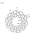
Fig. 5 illustrates a configuration of top portions of afirst rotor 42 and asecond rotor 51 according to the first embodiment; -
Fig. 6 is a block diagram illustrating a configuration of a transmission andreception controller 6 and aprocessor 7; -
Fig. 7 illustrates a configuration of top portions of afirst rotor 42 and asecond rotor 51 in a comparative example; -
Fig. 8 is a cross-sectional view illustrating a micrometer head 1a according to a second embodiment; and -
Fig. 9 is an exploded perspective view of the guide detectiontype rotary encoder 4a according to the second embodiment. - The particulars shown herein are by way of example and for purposes of illustrative discussion of the embodiments of the present invention only and are presented in the cause of providing what is believed to be the most useful and readily understood description of the principles and conceptual aspects of the present invention. In this regard, no attempt is made to show structural details of the present invention in more detail than is necessary for the fundamental understanding of the present invention, the description is taken with the drawings making apparent to those skilled in the art how the forms of the present invention may be embodied in practice.
- The following describes one embodiment of a guide detection type rotary encoder according to the present invention with reference to the drawings.
- An overall configuration of a micrometer head 1 mounting a guide detection type rotary encoder 4 according to a first embodiment is described with reference to
Fig. 1. Fig. 1 is a cross-sectional view illustrating a micrometer head 1 according to the first embodiment. - A micrometer head 1 has a
main body 2, aspindle 3 extending from themain body 2, and a guide detection type rotary encoder 4 installing thespindle 3 in the center. The micrometer head 1 also has a transmission andreception controller 6, aprocessor 7, and adisplay 8. The transmission andreception controller 6 controls transmission and reception between the controller and the guide detection type rotary encoder 4. Theprocessor 7 performs an arithmetic processing based on a signal from the transmission and reception controller 6 (the guide detection type rotary encoder 4). Thedisplay 8 displays a processing result by theprocessor 7. - A
main body 2 is formed in a substantially cylindrical shape and hasstorage spaces storage spaces internal division plate 23. On the wall of the spindle tip end side of the substantially cylindrical main body 2 (left side in the drawing) and on thedivision plate 23, throughholes spindle 3 passes through are formed. On the proximal end of the main body 2 (right side in the drawing), aninternal thread 26 is formed. The throughholes internal thread 26 are arranged on the same axis. - A
spindle 3 is formed in a substantially columnar shape and has acontact surface 31 to a measured object (not illustrated) in the tip end and aknob 32 in the proximal end. Theknob 32 rotates thespindle 3 externally. Thespindle 3 penetrates the throughholes main body 2, and both ends of the spindle protrude from themain body 2. On the outer circumference of thespindle 3, afeed screw 33 is also formed and threaded with theinternal thread 26 of themain body 2. With this configuration, thespindle 3 is advanced and retreated along inside the throughholes feed screw 33 and theinternal thread 26 when theknob 32 is rotated. Thefeed screw 33 is formed for 40 rotations, for example, at a 0.5 mm pitch, so that thespindle 3 can be moved for 20 mm. On the substantial center of thespindle 3, alinear key groove 34 is formed in the axial direction. - Next, a configuration of the guide detection type rotary encoder 4 is described with reference to
Fig. 1 through Fig. 3 .Fig. 2 is a perspective view of a guide detection type rotary encoder 4.Fig. 3 is an exploded perspective view of the guide detection type rotary encoder 4. As shown inFig. 2 andFig. 3 , the guide detection type rotary encoder 4 is configured with a firstrotary encoder 40 and a secondrotary encoder 50 and is stored in thestore space 22 of themain body 2. - The first
rotary encoder 40 includes astator 41, afirst rotor 42, and a firstrotary cylinder 43. - The
stator 41 has a throughhole 44 which aspindle 3 penetrates in a center of a circular plate and is fixed to theinternal division plate 23. Specifically, thestator 41 is fit over arim member 27 formed in a periphery of the throughhole 25 of theinternal division plate 23. - The
first rotor 42 has a throughhole 45 which thespindle 3 penetrates in a center of a circular plate and is placed in an axial direction opposing thestator 41 having a predetermined distance from thestator 41. - The first
rotating cylinder 43 into which thespindle 3 is penetrated is provided closer towards the tip end of thespindle 3 than thestator 41 and is supported such that thefirst rotor 42 can be rotated around the axis of thespindle 3. In other words, on the end of thestator 41 side of the firstrotating cylinder 43, arotor support 46 is formed along the outer circumference of thespindle 3, and thefirst rotor 42 is fit over therotor support 46. - The first
rotating cylinder 43 also has a screw-like key 47 screwed into the center from the outer circumference. The tip end of the key 47 protrudes from the inner circumference of the firstrotating cylinder 43 and is engaged with akey groove 34 in the outer circumference of thespindle 3. In other words, since a key 47 is engaged with akey groove 34 of thespindle 3, when the spindle is rotated, the firstrotating cylinder 43 is arranged to be rotated synchronically with thespindle 3. - In addition, a
first gear 48 is formed on the outer circumference of the firstrotating cylinder 43. Thegear 48 is provided on an end of the tip side of thespindle 3 in the firstrotating cylinder 43 and has a larger outer diameter dimension than the outer circumferences of the other areas of therotating cylinder 43. The number of gear teeth of thefirst gear 48 is set, for example, to be 40. - The second
rotary encoder 50 includes thestator 41, asecond rotor 51, a second rotating cylinder (support) 52, and a link-upgear 53. - The
stator 41 is that of the firstrotary encoder 40 and is a common component for therotary encoders - The
second rotor 51 has ahole 54 which can place thefirst rotor 42 in a center of a circular plate and is provided surrounding the outer circumference of thefirst rotor 42. Thesecond rotor 51 is also provided similar to thefirst rotor 42, in the axial direction opposing thestator 41 having a predetermined distance from thestator 41. In this way, the faces of eachrotor stator 41 form substantially the same plain surface. - The second
rotating cylinder 52 into which the first rotating cylinder 43 (except the area of the first gear 48) is penetrated is supported by the firstrotating cylinder 43. On the end of thestator 41 side of the secondrotating cylinder 52, thesecond rotor 51 is attached. In this way, thesecond rotor 51 is supported rotatably around the axis of thespindle 3. In other words, the first and the secondrotary encoders - Also, on the outer circumference of the second
rotating cylinder 52, asecond gear 55 is formed. Thegear 55 is provided on the end of the tip side of thespindle 3 in the secondrotating cylinder 52 and has substantially the same outer dimension as that of thegear 48 of the firstrotating cylinder 43. The number of gear teeth of thesecond gear 55 is set, for example, to be 41; i.e., one tooth more compared with the number of gear teeth of thefirst gear 48. - The link-up
gear 53 is rotatably supported by themain body 2, and engaged with both thefirst gear 48 and thesecond gear 55. In other words, the link-upgear 53 has a first link-upgear 53A which engages with thefirst gear 48, a second link-upgear 53B which engages with thesecond gear 55, and ashaft 53C which axially support these link-upgears gears first gear 48 and the first link-upgear 53A correspond to each other; and the modules for the other pair of thesecond gear 55 and the second link-upgear 53B correspond to each other. Therefore, when the firstrotating cylinder 43 rotates, the secondrotating cylinder 52 rotates smoothly via the link-upgear 53. - When this occurs, depending on the difference in the number of gear teeth between the
gear 48 and thegear 55, eachrotor gear 48 is set at 40, and that of thegear 55 is set at 41, thefirst rotor 42 rotates 40 times and thesecond rotor 51 rotates 39 times by the time thespindle 3 rotates 40 times within the range that thespindle 3 advances and retreats. - Additionally, the first
rotary encoder 40 and the secondrotary encoder 50 are arranged so that the absolute angle of eachrotor stator 41 outputs a phase signal which refers to a change of one cycle per rotation of thefirst rotor 42. Then, because thefirst rotor 42 rotates synchronically with that of thespindle 3, the phase signal with respect to thefirst rotor 42 refers to a change of the first cycle of the present invention by one rotation of thespindle 3. For instance, the phase signal refers to a change of forty cycles while thespindle 3 rotates 40 times. - The
stator 41 also outputs a phase signal which refers to a change of one cycle per rotation with respect to thesecond rotor 51. Then, since thesecond rotor 51 rotates 39 times by the time that thespindle 3 rotates 40 times, the phase signal with respect to thesecond rotor 51 refers to a change of 39 cycles by forty time rotations of thespindle 3. - Next, a detailed configuration of the
stator 41, thefirst rotor 42, and thesecond rotor 51 is described with reference toFig. 4 andFig. 5 .Fig. 4 illustrates a configuration of a top portion of astator 41.Fig. 5 illustrates a configuration of top portions of afirst rotor 42 and asecond rotor 51. - As shown in
Fig. 4 , on thestator 41 opposing thefirst rotor 42 and thesecond rotor 51, a first transmission winding 41 l, a second transmission winding 412, a third transmission winding 413, and a fourth transmission winding 414 are provided coaxially to thespindle 3. The first transmission winding 411 is formed in a substantially circular shape having a first diameter from the spindle 3 (rotation shaft). The second transmission winding 412 is formed in a substantially circular shape having a second diameter which is larger than the first diameter from the spindle 3 (rotation shaft). The third transmission winding 413 is formed in a substantially circular shape having a third diameter which is larger than the second diameter from the spindle 3 (rotation shaft). The fourth transmission winding 414 is formed in a substantially circular shape having a fourth diameter which is larger than the third diameter from the spindle 3 (rotation shaft). - As shown in
Fig. 4 , on thestator 41 opposing thefirst rotor 42 and thesecond rotor 51, a first reception winding 415, a second reception winding 416, a third reception winding 417, and a fourth reception winding 418 are provided coaxially to thespindle 3. The first throughfourth reception windings 415 through 418 are formed so that the distance from the spindle 3 (rotating shaft) can be changed periodically. The first reception winding 415 is formed between the first transmission winding 411 and the second transmission winding 412, and on the side of the first transmission winding 411. The second reception winding 416 is formed between the first transmission winding 411 and the second transmission winding 412, and on the side of the second transmission winding 412. The third reception winding 417 is formed between the third transmission winding 413 and the fourth transmission winding 414, and on the side of the third transmission winding 413. The fourth reception winding 418 is formed between the third transmission winding 413 and the fourth transmission winding 414, and on the side of the fourth transmission winding 414. The first reception winding 415 detects a flux generated by a below-described first flux coupling winding 421. The second reception winding 416 detects a flux generated by a below-described second flux coupling winding 422. The third reception winding 417 detects a flux generated by a below-described third flux coupling winding 511. The fourth reception winding 418 detects a flux generated by a below-described fourth flux coupling winding 512. - The first reception winding 415 is configured with three
reception windings 415a through 415c having different phases in the rotation direction. Thereception windings 415a through 415c are configured with an electric wire each arranged in a loop (diamond shape). Thereception windings 415a through 415c are arranged to be above/below the substrate in the area crossing each other so that the crossing area does not short. They are also arranged to be insulated and isolated respectively by connecting the winding at a viahole 415d to each other. The second reception winding 416 through the fourth reception winding 418 are configured in a similar manner as the first reception winding 415. - As shown in
Fig. 5 , on thefirst rotor 42 opposing thestator 41, the first flux coupling winding 421 and the second flux coupling winding 422, which are a flux coupling body, are provided coaxially to thespindle 3. The first flux coupling winding 421 and the second flux coupling winding 422 are formed in a gear shape having concaves and convexes so that the distance from the spindle 3 (rotation shaft) may respectively change N1 times and N2 times periodically at one rotation of thefirst rotor 42. The first flux coupling winding 421 can be coupled in magnetic flux with the first transmission winding 411. The second flux coupling winding 422 can be coupled in magnetic flux with the second transmission winding 412. - The first flux coupling winding 421 is formed in a gear shape, for example, having nine piece (N1) concaves and convexes. The second flux coupling winding 422 is formed in a gear shape, for example, having ten piece (N2) concaves and convexes. In other words, the number of concaves and convexes of the second flux coupling winding 422 is different by one from that of the first flux coupling winding 421.
- As shown in
Fig. 5 , on thesecond rotor 51 opposing thestator 41, the third flux coupling winding 511 and the fourth flux coupling winding 512, which are a flux coupling body, are provided coaxially to thespindle 3. The third flux coupling winding 511 and the fourth flux coupling winding 512 are formed having concaves and convexes so that the distance from the spindle 3 (rotation shaft) may respectively change N3 times and N4 times periodically at one rotation of thesecond rotor 51. The third flux coupling winding 511 can be coupled in magnetic flux with the third transmission winding 413. The fourth flux coupling winding 512 can be coupled in magnetic flux with the fourth transmission winding 414. - The third flux coupling winding 511 is formed in a gear shape, for example, having nine piece (N1) concaves and convexes. The fourth flux coupling winding 512 is formed in a gear shape, for example, having ten piece (N2) concaves and convexes. In other words, the number of concaves and convexes of the fourth flux coupling winding 512 is different by one from that of the third flux coupling winding 511.
- Next, a detailed configuration of a transmission and
reception controller 6 and aprocessor 7 is described with reference toFig. 6. Fig. 6 is a block diagram illustrating a configuration of a transmission andreception controller 6 and aprocessor 7. - First, the transmission and
reception controller 6 is described. The transmission andreception controller 6 includes a first transmission andreception controller 61 which controls a transmission and reception of a signal with respect to the firstrotary encoder 40, and a second transmission andreception controller 62 which controls a transmission and reception of a signal with respect to the secondrotary encoder 50. - The first transmission and
reception controller 61 includes afirst transmission controller 63 and afirst reception controller 64. Thefirst transmission controller 63 transmits to thestator 41a predetermined AC signal for the first rotor 42 (for the first transmission winding 411 and the second transmission winding 412). Thefirst reception controller 64 receives a phase signal of thefirst rotor 42 from the stator 41 (the first reception winding 415 and the second reception winding 416). In this embodiment, the phase signal refers to a signal indicating a phase difference between a signal based on the first flux coupling winding 421 and a signal based on the second flux coupling winding 422. - Likewise, the second transmission and
reception controller 62 includes asecond transmission controller 65 and asecond reception controller 66. Thesecond transmission controller 65 transmits to thestator 41 a predetermined AC signal for the second rotor 51 (for the third transmission winding 413). Thesecond reception controller 66 receives a phase signal of thesecond rotor 51 from the stator 41 (the third reception winding 417 and the fourth reception winding 418). In this embodiment, the phase signal refers to a signal indicating a phase difference between a signal based on the third flux coupling winding 511 and a signal based on the fourth flux coupling winding 512. Thefirst reception controller 64 and thesecond reception controller 66 output to the processor 7 a phase signal of eachrotor stator 41. - Next, the
processor 7 is described. Theprocessor 7 includes arotation angle calculator 71, arotation phase calculator 72, and aspindle position calculator 73. Therotation angle calculator 71 calculates each rotation angle θ1 and θ2 of thefirst rotor 42 and thesecond rotor 51. Therotation phase calculator 72 calculates a rotation phase of thespindle 3 based on the rotation angle θ1 and θ2 of eachrotor rotation angle calculator 71. Thespindle position calculator 73 calculates an absolute position of thespindle 3 based on the rotation phase of thespindle 3 calculated in therotation phase calculator 72. - The
rotation angle calculator 71 includes a firstrotation angle calculator 74 and a secondrotation angle calculator 75. The firstrotation angle calculator 74 calculates a rotation angle θ1 of thefirst rotor 42 based on the phase signal from thefirst reception controller 64. The secondrotation angle calculator 75 calculators a rotation angle θ2 of thesecond rotor 51 based on the phase signal from thesecond reception controller 66. - The first
rotation angle calculator 74 calculates a rotation angle θ1 of thefirst rotor 42 as an absolute angle within one rotation (0°< θ1 <360°) based on the phase signal from thefirst reception controller 64. In this embodiment, the phase signal from thefirst reception controller 64 does not generate the same phase within one rotation of thefirst rotor 42. In the firstrotation angle calculator 74, the rotation angle θ1 of thefirst rotor 42 and the phase signal are preset to be memorized as a one-to-one relationship. Through this, according to the phase signal output from thefirst reception controller 64, the rotation angle θ1 of thefirst rotor 42 is primarily determined; the absolute angle within one rotation of thefirst rotor 42 is calculated. - Also, the second
rotation angle calculator 75, in a similar manner as the firstrotation angle calculator 74, calculates a rotation angle θ2 of thesecond rotor 51 as the absolute angle within one rotation based on the phase signal from thesecond reception controller 66. - The
rotation phase calculator 72 includes adifference calculator 76 and a totalrotation phase calculator 77. Thedifference calculator 76 calculates a difference θ3 of the rotation angles θ1 and θ2 of eachrotor rotation angle calculator 71. The totalrotation phase calculator 77 calculates a total rotation phase of thespindle 3 based on the difference θ3. - In the total
rotation phase calculator 77, the difference θ3 and the total rotation phase of thespindle 3 are preset to be memorized as a one-to-one relationship. In other words, a difference of the rotation angles θ1 and θ2 of eachrotor spindle 3 rotates 40 times within the range that thespindle 3 advances and retreats. Therefore, the difference θ3 is calculated within the range of 0° to 360°; the total rotation phase θT of thespindle 3 is primarily calculated according to the difference θ3. - In the
spindle position calculator 73, a move pitch (0.5 mm) per one rotation of thespindle 3 is preset to be memorized. Then, in thespindle position calculator 73, the total movement of thespindle 3, i.e., the absolute position of thespindle 3, is calculated by multiplying the move pitch (0.5 mm) and the total rotation phase θT. Thedisplay 8 displays, for example, the absolute position of thespindle 3 using a digital display. - Next, an operation of the embodiment having this kind of configuration is described. When a
spindle 3 is rotated using theknob 32, thespindle 3 is advanced or retreated in the axial direction by the thread of theinternal thread 26 of themain body 2 and thefeed screw 33 of thespindle 3. When thespindle 3 rotates, the firstrotating cylinder 43 rotates with thespindle 3 by the key 47 engaged with thekey groove 34 of thespindle 3. - When the first
rotating cylinder 43 rotates, thefirst rotor 42 rotates with the firstrotating cylinder 43. The rotation of thefirst rotor 42 is detected by thestator 41 and is transmitted to thefirst reception controller 64. Then, the rotation angle θ1 within one rotation of thefirst rotor 42 is calculated in the firstrotation angle calculator 74. - In this embodiment, the
first rotor 42 rotates synchronically with thespindle 3; a rotation angle θ1 within one rotation of thefirst rotor 42 refers to a rotation angle within one rotation of thespindle 3. - When the first
rotating cylinder 43 rotates, the first link-upgear 53A of the link-upgear 53 engaged with thegear 48 of the firstrotating cylinder 43 also rotates. Further, thegear 55 of the secondrotating cylinder 52 that is engaged with the second link-upgear 53B of the link-upgear 53 also rotates as does thesecond rotor 51 along with the secondrotating cylinder 52. A phase signal within one rotation of thesecond rotor 51 is detected by thestator 41 and transmitted to thesecond reception controller 66. Then, a rotation angle θ2 within one rotation of thesecond rotor 51 is calculated in the secondrotation angle calculator 75. - Then, in the
rotation phase calculator 72, a difference θ3 of the rotation angles θ1 and θ2 of eachrotor spindle 3 is calculated based on the difference θ3. Finally, in thespindle position calculator 73, the absolute position of thespindle 3 is calculated based on the total rotation phase θT and the transmission pitch (0.5mm) of thespindle 3 to be displayed in thedisplay 8. - An effect of the embodiment is described with reference of a comparative example according to
Fig. 7. Fig. 7 illustrates a configuration of top portions of afirst rotor 42 and asecond rotor 51 in a comparative example. The comparative example, as shown inFig. 7 , differs from the embodiment in that it does not have a fourth flux coupling winding 512. The comparative example also does not have a fourth transmission winding 414 and a fourth reception winding 418, although this illustration is omitted. Additionally, in the comparative example, a third flux coupling winding 511 is formed in a gear shape having two piece (N3) concaves and convexes. - For instance, in the above-described comparative example, in a case where 25 mm is lengthened at a screw pitch of 0.5 mm (a
first rotor 42 rotates 50 times), strict accuracy is required as follows. - The range of use of the rotation angle of the
second rotor 51 with respect to thefirst rotor 42 is 180° (=360°/2). The rotation angle of thesecond rotor 51 with respect to thefirst rotor 42 per one rotation of thefirst rotor 42 becomes a maximum of 180°/50=3.6°. The accuracy (including all errors such as mechanic errors) of the secondrotary encoder 50 necessary to detect the rotation position needs to be half of that angle, which is 3.6°/2 = 1.8° or below. On the other hand, the accuracy of the second rotary encoder 50 (excluding mechanical errors) is about 180°/300 = 0.6°. Therefore, the allowance of the rotation accuracy of the mechanism part of the second rotor 51 (total allowance of component accuracy and assembly accuracy of the mechanism part of the second rotor 51) is within 1.8°- 0.6° = 1.2°; and thus, strict accuracy is required. - In addition, in the above-described comparative example, when the concaves and convexes having a gear shape of the third flux coupling winding 511 become even smaller (for example, one piece (N3)) in order to expand the range of use of the rotation position of the
first rotor 42 and thesecond rotor 51, accuracy of the secondrotary encoder 50 worsens. On the other hand, when the concaves and convexes having a gear shape of the third flux coupling winding 511 becomes large, the range of use of the rotation angle of thesecond rotor 51 with respect to thefirst rotor 42 becomes smaller while accuracy of the second rotary encoder 50 (excluding a mechanic error) improves. Therefore, it becomes necessary to set the rotation accuracy of the mechanism part of the secondrotary encoder 50 even more strictly. - In contrast, in the embodiment, two tracks having only one different pitch inside are formed and two more tracks having only one different pitch outside are formed. Therefore, an absolute position within one rotation can be detected with sufficient accuracy inside and outside. Besides, according to a configuration of the embodiment, unlike with that of the comparative example, component accuracy and assembly accuracy required for the mechanism part can be reduced; the manufacturing burden can be reduced.
- Also, in the embodiment, the rotation angle of the second
rotary encoder 50 with respect to the firstrotary encoder 40 can be used for one rotation. Therefore, according the embodiment, the length range of thespindle 3 can be enlarged. Additionally, when a configuration of the embodiment is applied to a device having the same length range of the embodiment, component accuracy and assembly accuracy required for the mechanism part can be reduced. - Next, an overall configuration of a micrometer head 1a mounting a guide detection
type rotary encoder 4a according to a second embodiment with reference toFig. 8 is described.Fig. 8 is a cross-sectional view illustrating a micrometer head 1a according to the second embodiment. Also, in the second embodiment, the same numerals are assigned to the same configuration as that of the first embodiment and the descriptions are omitted. - As shown in
Fig. 8 , the micrometer head 1a has thespindle 3a, and the guide detectiontype rotary encoder 4a installing thespindle 3a in the center which are different from the first embodiment. Other than this, the micrometer head 1a has the same configuration as the first embodiment. - A
spindle 3a is formed, in a similar manner as the first embodiment, in a substantially cylindrical shape and has thecontact surface 31 to a measured object (not illustrated) in the tip end and theknob 32 in the proximal end. - In the central area of the
spindle 3a, unlike the first embodiment, twokey grooves key groove 34a is provided parallel to the axis of thespindle 3a linearly. The secondkey groove 34b is provided helical to thespindle 3a. The positions of the beginning point and ending point of the firstkey groove 34a and the secondkey groove 34b are substantially consistent in the axial direction of thespindle 3a. In other words, the firstkey groove 34a and the secondkey groove 34b are formed in substantially the same range in the axial direction of thespindle 3a. - Also, when the
spindle 3a advances and retreats, thekey grooves main body 2 with thespindle 3a. However, anouter frame 11 is provided so that thekey grooves spindle 3a advances at the maximum externally. - Next, a description of the guide detection
type rotary encoder 4a follows.Fig. 9 is an exploded perspective view of the guide detectiontype rotary encoder 4a. As shown inFig. 9 , the guide detectiontype rotary encoder 4a is configured with a firstrotary encoder 40a and a secondrotary encoder 50a and is provided in astore space 22 of themain body 2. - The first
rotary encoder 40a has astator 41a and a key 47a engaged with thekey groove 34a as well as afirst rotor 42a to be rotated centering around thespindle 3a. - The
stator 41a has thespindle 3a inserted and is fixed in the front endinner wall 28 of thestore space 22. - The
first rotor 42a is provided immediately outside thespindle 3a. Thefirst rotor 42a is placed in the axial direction opposing thestator 41a having a predetermined distance from thestator 41a. Thefirst rotor 42a includes afirst rotor plate 48a which is rotated while opposing thestator 41a in pair with thestator 41a, a firstrotating cylinder 43a which supports the rotation of thefirst rotor plate 48a centering thespindle 3a, and a first key 47a engaged with the firstkey groove 34a. Thefirst rotor plate 48a is a circular platelet having a hole through which thespindle 3a passes. - The first
rotating cylinder 43a is in a cylindrical shape that is fit over thespindle 3a and connected to the back surface of thefirst rotor plate 48a to support the rotation of thefirst rotor plate 48a. In the firstrotating cylinder 43a, two holes 43aa and 43ab are provided which are formed to be penetrated perpendicular to the axis. The first key 47a is threaded into the first hole 43aa. Also, the second hole 43ab is formed in an elongated hole shape having a length in a circumferential direction of the firstrotating cylinder 43a. - The second
rotary encoder 50a has astator 41a and a key 47b engaged with thekey groove 34b as well as asecond rotor 51a provided rotatably around thespindle 3a. - The
second rotor 51a is provided outside thefirst rotor 42a so as to surround it. Thesecond rotor 51a is placed in an axial direction opposing thestator 41a having a predetermined distance from thestator 41a. Thesecond rotor 51a, similar to thefirst rotor 42a, includes asecond rotor plate 55a which is rotated while opposing thestator 41a in pair with thestator 41a, a secondrotating cylinder 52a which supports the rotation of thesecond rotor plate 55a centering thespindle 3a, and a second key 47b engaged with the secondkey groove 34b. - The
second rotor plate 55a is an annular plate having an inner hole the size of which loosely fits thefirst rotor plate 48a inside. The secondrotating cylinder 52a is connected to the back surface of thesecond rotor plate 55a and is in a cylindrical shape having a hole which loosely fits the firstrotating cylinder 43a inside. - The second
rotating cylinder 52a has a hole 52aa which is formed to be penetrated perpendicular to the axis. The second key 47b is threaded into the second hole 52aa. Also, the second key 47b passes through the second hole 43ab which has an elongated hole shape of the firstrotating cylinder 43a and is engaged with the secondkey groove 34b. - Then, the second
rotating cylinder 52a has a bearing portion 52ab which receives thespindle 3a on the opposite side from thestator 41a with thefirst rotor 42a in between. Also, in the spindle axis direction, the position of the second key 47b is substantially the same as that of the first key 47a provided on the firstrotating cylinder 43a. - In addition, on the front end side
inner wall 28 of thestore space 22 fixing thestator 41a, thespindle bearing 27a is extended slightly towards the back end side compared with thestator 41a. The spindle bearing 43ac of the firstrotating cylinder 43a is also extended slightly towards the side of thestator 41a compared with thefirst rotor plate 48a. Since the spindle bearing 43ac of the firstrotating cylinder 43a touches the spindle bearing 27a of themain body 2, a gap is secured properly between thestator 41a and thefirst rotor plate 48a. - Furthermore, a coil spring (biasing unit) which is not illustrated is set between the second
rotating cylinder 52a and theinternal division plate 23. Thesecond rotor 51a is arranged to bias towards thestator 41a side. With thefirst rotor 42a being pressed towards the inner wall of the secondrotating cylinder 52a, thefirst rotor 42a is biased towards thestator 41a. - Next, an operation of the micrometer head 1a according to the second embodiment including the above-described configuration is illustrated. When the
spindle 3a is rotated using theknob 32, thespindle 3a is advanced and retreated in the axial direction by the thread of theinternal thread 26 of themain body 2 and thefeed screw 33 of thespindle 3a. - Also, when the
spindle 3a is rotated, the firstrotating cylinder 43a and the secondrotating cylinder 52a are rotated along with the rotation of thespindle 3a as the first key 47a of the firstrotating cylinder 43a and the second key 47b of the secondrotating cylinder 52a are respectably engaged with a firstkey groove 34a and the secondkey groove 34b of thespindle 3a. When this occurs, since the firstrotating cylinder 43a receives thespindle 3a by the spindle bearing 43ac, the firstrotating cylinder 43a rotates on the basis of thespindle 3a. Further, since the secondrotating cylinder 52a receives thespindle 3a by the bearing portion 622, the secondrotating cylinder 52a also rotates on the basis of thespindle 3a. - Then, the first
key groove 34a and the secondkey groove 34b have a different lead angle from each other; and thus, the firstrotating cylinder 43a and the secondrotating cylinder 52a are rotated per one rotation of thespindle 3a at a different rotating amount (rotation phase). When the first and secondrotating cylinder spindle 3a, thefirst rotor plate 48a is rotated along with the firstrotating cylinder 43a, and thesecond rotor plate 55a is rotated along with the secondrotating cylinder 52a. In other words, in the second embodiment, thefirst rotor 42a rotates at a different rotation speed from that of thesecond rotor 51a in a similar manner as the first embodiment. - In the second embodiment, on the
first rotor 42a opposing thestator 41, first and secondflux coupling windings second rotor 51a opposing thestator 41, third and fourthflux coupling windings stator 41a opposing the first andsecond rotors fourth transmission windings 411 through 414 and first throughfourth reception windings 415 through 418 are formed. - A micrometer head 1a according to the second embodiment is configured substantially in a similar manner as the first embodiment, and thus it has the similar effect as the first embodiment.
- As described above, one embodiment of the guide detection type rotary encoder according to the present invention is described. However, the present invention is not limited to what is explained in the above embodiment. Changes, additions and replacements may be made within the scope of the intent of the invention. For example, the first through third flux coupling bodies can be holes or concaves formed on an electrode and conductive plate instead of the first through fourth
flux coupling windings - Also, the above embodiment is intended to detect which rotations of the
first rotor 42 based on the positional relation of thefirst rotor 42 and thesecond rotor 51. However, the present invention may be intended to detect which rotations of thesecond rotor 51 based on the positional relation of thefirst rotor 42 and thesecond rotor 51. - In addition, in the above embodiment, N1=N3, N2=N4 and N4-N3=N2-N1=1. However, it is also applicable that N1≠N3, N2≠N4, N4-N3≠N2-N1≠1, and N1=N4, and N2=N3.
- Furthermore, the above embodiment is using an electromagnetic guidance type rotary encoder. However, the present invention is also applicable to a capacitor ionization type or photoelectric rotary encoder.
- It is noted that the foregoing examples have been provided merely for the purpose of explanation and are in no way to be construed as limiting of the present invention. While the present invention has been described with reference to exemplary embodiments, it is understood that the words which have been used herein are words of description and illustration, rather than words of limitation. Changes may be made, within the purview of the appended claims, as presently stated and as amended, without departing from the scope and spirit of the present invention in its aspects. Although the present invention has been described herein with reference to particular structures, materials and embodiments, the present invention is not intended to be limited to the particulars disclosed herein; rather, the present invention extends to all functionally equivalent structures, methods and uses, such as are within the scope of the appended claims.
- The present invention is not limited to the above described embodiments, and various variations and modifications may be possible without departing from the scope of the present invention.
Claims (8)
- A rotary encoder comprising:a stator;a first rotor affixed to a rotation shaft and rotatable with the rotation shaft, the first rotor opposing the stator in an axial direction;a second rotor positioned about the external circumference of the first rotor and rotatable relative to the first rotor, the second rotor opposing the stator in the axial direction;a rotation transmitter configured to rotate the rotation shaft, and further configured to rotate the second rotor at a different speed than the first rotor;first and second angle detection tracks coaxially positioned about the rotation shaft on a surface of the stator opposing the first rotor and on a surface of the first rotor opposing the stator, wherein the first angle detection track is radially inside of the second angle detection track; andthird and fourth angle detection tracks coaxially positioned about the rotation shaft on a surface of the stator opposing the second rotor and on a surface of the second rotor opposing the stator, wherein the third angle detection is radially inside of the fourth angle detection track,wherein:the first angle detection track generates an N1 time cyclic change at one rotation of the first rotor;the second angle detection track generates an N2 time cyclic change at one rotation of the first rotor;the third angle detection track generates an N3 time cyclic change at one rotation of the second rotor;the fourth angle detection track generates an N4 time cyclic change at one rotation of the second rotor; andN1 is different from N2, and N3 is different from N4.
- The rotary encoder according to claim 1, wherein the first angle detection track comprises:a first transmission winding coaxially positioned about the rotation shaft on the surface of the stator opposing the first rotor;a first reception winding coaxially positioned about the rotation shaft on the surface of the stator opposing the first rotor, in correspondence association with the first transmission winding; anda first flux coupling body coaxially positioned about the rotation shaft on the surface of the first rotor opposing the stator and magnetically combining the first transmission winding and the first reception winding.
- The rotary encoder according to claim 2, wherein the second angle detection track comprises:a second transmission winding coaxially positioned about the rotation shaft on the surface of the stator opposing the first rotor and positioned radially outside the first transmission winding;a second reception winding coaxially positioned about the rotation shaft on the surface of the stator opposing the first rotor, in correspondence association with the second transmission winding and positioned radially outside the first transmission winding; anda second flux coupling body coaxially positioned about the rotation shaft on the surface of the first rotor opposing the stator and magnetically combining the second transmission winding and the second reception winding, and positioned radially outside the first flux coupling body.
- The rotary encoder according to claim 3, wherein the third angle detection track comprises:a third transmission winding coaxially positioned about the rotation shaft on the surface of the stator opposing the second rotor and positioned radially outside the second transmission winding;a third reception winding coaxially positioned about the rotation shaft on the surface of the stator opposing the second rotor, in correspondence association with the third transmission winding, and positioned radially outside the second transmission winding; anda third flux coupling body coaxially positioned about the rotation shaft on the surface of the second rotor opposing the stator, magnetically combining the third transmission winding and the third reception winding, and positioned radially outside the second flux coupling body.
- The rotary encoder according to claim 4, wherein the fourth angle detection track comprises:a fourth transmission winding coaxially positioned about the rotation shaft on the surface of the stator opposing the second rotor and positioned radially outside the third transmission winding;a fourth reception winding coaxially positioned about the rotation shaft on the surface of the stator opposing the second rotor, in correspondence association with the fourth transmission winding and positioned radially outside the third transmission winding; anda fourth flux coupling body coaxially positioned about the rotation shaft on the surface of the second rotor opposing the stator, magnetically combining the fourth transmission winding and the fourth reception winding, and positioned radially outside the third flux coupling body.
- The rotary encoder according to any one of claims 1 to 5, wherein the difference between N1 and N2 is "1" and that of N3 and N4 is "1".
- The rotary encoder according to any one of claims 1 to 6, wherein N1 = N3 and N2 = N4.
- The rotary encoder according to any one of claims 1 to 6, wherein N1 = N4 and N2 = N3.
Applications Claiming Priority (1)
| Application Number | Priority Date | Filing Date | Title |
|---|---|---|---|
| JP2009239261A JP5540308B2 (en) | 2009-10-16 | 2009-10-16 | Rotary encoder |
Publications (3)
| Publication Number | Publication Date |
|---|---|
| EP2312272A2 true EP2312272A2 (en) | 2011-04-20 |
| EP2312272A3 EP2312272A3 (en) | 2014-01-15 |
| EP2312272B1 EP2312272B1 (en) | 2015-01-07 |
Family
ID=43416838
Family Applications (1)
| Application Number | Title | Priority Date | Filing Date |
|---|---|---|---|
| EP10187651.4A Active EP2312272B1 (en) | 2009-10-16 | 2010-10-15 | Rotary Encoder |
Country Status (4)
| Country | Link |
|---|---|
| US (1) | US9234771B2 (en) |
| EP (1) | EP2312272B1 (en) |
| JP (1) | JP5540308B2 (en) |
| CN (1) | CN102121832B (en) |
Cited By (3)
| Publication number | Priority date | Publication date | Assignee | Title |
|---|---|---|---|---|
| JP2014119367A (en) * | 2012-12-18 | 2014-06-30 | Mitsutoyo Corp | Induction detection type rotary encoder |
| EP2620739A3 (en) * | 2012-01-25 | 2014-10-29 | Mitutoyo Corporation | Inductive detection type rotary encoder |
| DE102021210279A1 (en) | 2020-12-08 | 2022-06-09 | Dr. Johannes Heidenhain Gmbh | Scanning element and inductive position measuring device with this scanning element |
Families Citing this family (24)
| Publication number | Priority date | Publication date | Assignee | Title |
|---|---|---|---|---|
| JP5133199B2 (en) * | 2008-10-28 | 2013-01-30 | 株式会社ミツトヨ | Inductive detection type rotary encoder |
| JP6239824B2 (en) * | 2013-01-18 | 2017-11-29 | 株式会社ミツトヨ | Inductive detection type rotary encoder |
| JP2015094725A (en) * | 2013-11-13 | 2015-05-18 | 株式会社東海理化電機製作所 | Position detection device |
| DE102014208642B4 (en) * | 2014-05-08 | 2025-11-13 | Robert Bosch Gmbh | Sensor arrangement for detecting rotation angles on a rotating component in a vehicle |
| CN104061887B (en) * | 2014-06-18 | 2017-06-16 | 温州市特种设备检测中心 | Measure the detection car of crane runway |
| DE102015016300A1 (en) | 2014-12-26 | 2016-06-30 | Mitutoyo Corporation | Inductive detection type rotary encoder |
| FR3031588B1 (en) * | 2015-01-13 | 2018-11-16 | Hutchinson | INDUCTIVE DISPLACEMENT SENSORS |
| GB201513881D0 (en) * | 2015-08-06 | 2015-09-23 | Skf Ab | Absolute angle determination |
| US10030963B2 (en) * | 2015-10-01 | 2018-07-24 | Raytheon Company | Multidimensional angle determination using fine position sensors |
| DE102016201851B4 (en) * | 2016-02-08 | 2026-04-30 | Robert Bosch Gmbh | Sensor device and method for determining at least one rotational property of a rotating element |
| DE102016211832B3 (en) * | 2016-06-30 | 2017-08-17 | Robert Bosch Gmbh | Angle of rotation sensor, stator element and rotor element for this |
| US10330542B1 (en) * | 2017-04-20 | 2019-06-25 | Trw Automotive U.S. Llc | Torque sensor assembly for vehicle power steering systems |
| DE102020205202A1 (en) * | 2020-04-23 | 2021-10-28 | Dr. Johannes Heidenhain Gesellschaft Mit Beschränkter Haftung | Inductive angle measuring device |
| EP4012350B1 (en) * | 2020-12-08 | 2023-03-15 | Dr. Johannes Heidenhain GmbH | Scanning element and inductive position measuring device with the same |
| US11598654B2 (en) * | 2020-12-14 | 2023-03-07 | Microchip Technology Inc. | High resolution angular inductive sensor and associated method of use |
| US11898887B2 (en) | 2021-03-25 | 2024-02-13 | Microchip Technology Incorporated | Sense coil for inductive rotational-position sensing, and related devices, systems, and methods |
| CN117501071A (en) | 2021-06-11 | 2024-02-02 | 微芯片技术股份有限公司 | Sensing coils and related devices, systems and methods for inductive linear position sensing |
| WO2023015068A1 (en) | 2021-08-05 | 2023-02-09 | Microchip Technology Incorporated | Inductive angular-position sensors, and related devices, systems, and methods |
| US12339139B2 (en) | 2021-09-28 | 2025-06-24 | Microchip Technology Incorporated | Angular-position sensor |
| ES2994907T3 (en) * | 2021-10-25 | 2025-02-03 | Heidenhain Gmbh Dr Johannes | Inductive angle measuring device |
| CN118946782A (en) | 2022-04-01 | 2024-11-12 | 微芯片技术股份有限公司 | Target for sensing angular position sensors |
| US12411001B2 (en) | 2022-04-01 | 2025-09-09 | Microchip Technology Incorporated | Target for inductive angular-position sensing |
| US12618692B2 (en) | 2023-02-24 | 2026-05-05 | Microchip Technology Incorporated | Rotary inductive position sensing with 60° phase-shifted sense signals, and related apparatuses and methods |
| EP4484897B1 (en) * | 2023-06-26 | 2025-08-06 | Dr. Johannes Heidenhain GmbH | Inductive angle measuring device |
Citations (2)
| Publication number | Priority date | Publication date | Assignee | Title |
|---|---|---|---|---|
| JPH10213407A (en) | 1996-11-29 | 1998-08-11 | Dr Johannes Heidenhain Gmbh | Scanning member for position measuring device |
| JP2009239261A (en) | 2008-03-07 | 2009-10-15 | Panasonic Corp | Electronic unit and electronic apparatus |
Family Cites Families (16)
| Publication number | Priority date | Publication date | Assignee | Title |
|---|---|---|---|---|
| JPH0371010A (en) * | 1989-08-10 | 1991-03-26 | Mitsubishi Kasei Corp | Absolute position counter |
| US5796248A (en) * | 1994-09-19 | 1998-08-18 | Ford Motor Company | Method and apparatus for commutating a three-phase variable reluctance motor |
| JPH10185623A (en) * | 1996-12-24 | 1998-07-14 | Yaskawa Electric Corp | Multi-turn type absolute encoder |
| JP2002116057A (en) * | 2000-10-06 | 2002-04-19 | Yaskawa Electric Corp | Multi-rotational absolute value encoder |
| JP4088073B2 (en) * | 2002-01-11 | 2008-05-21 | 株式会社ミツトヨ | Absolute position measuring device |
| JP4319930B2 (en) * | 2004-03-17 | 2009-08-26 | 株式会社ミツトヨ | Inductive displacement detector and micrometer |
| JP4533165B2 (en) * | 2005-01-28 | 2010-09-01 | 株式会社ミツトヨ | Absolute position measuring device |
| JP4869769B2 (en) * | 2005-04-19 | 2012-02-08 | 株式会社ミツトヨ | Absolute rotary encoder and micrometer |
| CN100420914C (en) | 2005-04-19 | 2008-09-24 | 三丰株式会社 | Absolute Rotary Encoders and Micrometers |
| JP4732050B2 (en) | 2005-07-22 | 2011-07-27 | 株式会社ミツトヨ | Measuring instrument |
| FR2919385B1 (en) * | 2007-07-24 | 2009-10-09 | Moving Magnet Tech Mmt | NON-CONTACT MAGNETIC SENSOR WITH ABSOLUTE MULTITOUR POSITION WITH THROUGH SHAFT |
| JP5112779B2 (en) * | 2007-08-03 | 2013-01-09 | 株式会社ミツトヨ | Absolute position measuring device |
| JP5242122B2 (en) * | 2007-10-16 | 2013-07-24 | Ntn株式会社 | Drive shaft axial torque measuring device and measuring method |
| DE102008015837A1 (en) * | 2008-03-27 | 2009-10-01 | Dr. Johannes Heidenhain Gmbh | Position measuring device and method for its operation |
| JP5133199B2 (en) * | 2008-10-28 | 2013-01-30 | 株式会社ミツトヨ | Inductive detection type rotary encoder |
| US9163926B2 (en) * | 2012-01-25 | 2015-10-20 | Mitutoyo Corporation | Inductive detection type rotary encoder |
-
2009
- 2009-10-16 JP JP2009239261A patent/JP5540308B2/en active Active
-
2010
- 2010-10-11 CN CN201010577014.1A patent/CN102121832B/en active Active
- 2010-10-13 US US12/903,467 patent/US9234771B2/en active Active
- 2010-10-15 EP EP10187651.4A patent/EP2312272B1/en active Active
Patent Citations (2)
| Publication number | Priority date | Publication date | Assignee | Title |
|---|---|---|---|---|
| JPH10213407A (en) | 1996-11-29 | 1998-08-11 | Dr Johannes Heidenhain Gmbh | Scanning member for position measuring device |
| JP2009239261A (en) | 2008-03-07 | 2009-10-15 | Panasonic Corp | Electronic unit and electronic apparatus |
Cited By (6)
| Publication number | Priority date | Publication date | Assignee | Title |
|---|---|---|---|---|
| EP2620739A3 (en) * | 2012-01-25 | 2014-10-29 | Mitutoyo Corporation | Inductive detection type rotary encoder |
| US9163926B2 (en) | 2012-01-25 | 2015-10-20 | Mitutoyo Corporation | Inductive detection type rotary encoder |
| JP2014119367A (en) * | 2012-12-18 | 2014-06-30 | Mitsutoyo Corp | Induction detection type rotary encoder |
| DE102021210279A1 (en) | 2020-12-08 | 2022-06-09 | Dr. Johannes Heidenhain Gmbh | Scanning element and inductive position measuring device with this scanning element |
| EP4012349A1 (en) | 2020-12-08 | 2022-06-15 | Dr. Johannes Heidenhain GmbH | Scanning element and inductive position measuring device with the same |
| US11841248B2 (en) | 2020-12-08 | 2023-12-12 | Dr. Johannes Heidenhain Gmbh | Scanning element and inductive position measuring device having a scanning element |
Also Published As
| Publication number | Publication date |
|---|---|
| JP5540308B2 (en) | 2014-07-02 |
| EP2312272B1 (en) | 2015-01-07 |
| EP2312272A3 (en) | 2014-01-15 |
| CN102121832B (en) | 2014-12-03 |
| CN102121832A (en) | 2011-07-13 |
| JP2011085504A (en) | 2011-04-28 |
| US9234771B2 (en) | 2016-01-12 |
| US20110227562A1 (en) | 2011-09-22 |
Similar Documents
| Publication | Publication Date | Title |
|---|---|---|
| EP2312272B1 (en) | Rotary Encoder | |
| EP2182329B1 (en) | Induction detecting rotary encoder | |
| US7584551B2 (en) | Absolute position measuring apparatus | |
| KR101476564B1 (en) | Magnetic multi-turn absolute position detection device | |
| JP5022724B2 (en) | Absolute position measuring device | |
| US20130090890A1 (en) | Absolute position measuring device and method | |
| US9243884B2 (en) | Inductive detection type rotary encoder | |
| EP1342646A2 (en) | Rotation-angle detecting device capable of detecting absolute angle with simple configuration | |
| US11448524B2 (en) | Multipole magnet for use with a pitched magnetic sensor | |
| US12434761B2 (en) | Stroke sensor | |
| EP1746382B1 (en) | Measurement instrument | |
| JP2009276137A (en) | Digital display displacement measuring instrument | |
| US20080012554A1 (en) | Rotary angle sensing system | |
| JP2006090982A (en) | Rotation angle detector | |
| JP4866653B2 (en) | Absolute position measuring device | |
| JP4982243B2 (en) | Digital display displacement measuring instrument | |
| CN209431984U (en) | A Micrometer Based on Displacement Measurement of Rotating Magnetic Field | |
| JP2011007500A (en) | Instrument for measuring inside | |
| JP2004125440A (en) | Rotating angle detecting device |
Legal Events
| Date | Code | Title | Description |
|---|---|---|---|
| PUAI | Public reference made under article 153(3) epc to a published international application that has entered the european phase |
Free format text: ORIGINAL CODE: 0009012 |
|
| AK | Designated contracting states |
Kind code of ref document: A2 Designated state(s): AL AT BE BG CH CY CZ DE DK EE ES FI FR GB GR HR HU IE IS IT LI LT LU LV MC MK MT NL NO PL PT RO RS SE SI SK SM TR |
|
| AX | Request for extension of the european patent |
Extension state: BA ME |
|
| PUAL | Search report despatched |
Free format text: ORIGINAL CODE: 0009013 |
|
| AK | Designated contracting states |
Kind code of ref document: A3 Designated state(s): AL AT BE BG CH CY CZ DE DK EE ES FI FR GB GR HR HU IE IS IT LI LT LU LV MC MK MT NL NO PL PT RO RS SE SI SK SM TR |
|
| AX | Request for extension of the european patent |
Extension state: BA ME |
|
| RIC1 | Information provided on ipc code assigned before grant |
Ipc: G01D 5/245 20060101AFI20131206BHEP |
|
| 17P | Request for examination filed |
Effective date: 20140211 |
|
| RBV | Designated contracting states (corrected) |
Designated state(s): AL AT BE BG CH CY CZ DE DK EE ES FI FR GB GR HR HU IE IS IT LI LT LU LV MC MK MT NL NO PL PT RO RS SE SI SK SM TR |
|
| GRAP | Despatch of communication of intention to grant a patent |
Free format text: ORIGINAL CODE: EPIDOSNIGR1 |
|
| INTG | Intention to grant announced |
Effective date: 20140731 |
|
| GRAS | Grant fee paid |
Free format text: ORIGINAL CODE: EPIDOSNIGR3 |
|
| GRAA | (expected) grant |
Free format text: ORIGINAL CODE: 0009210 |
|
| AK | Designated contracting states |
Kind code of ref document: B1 Designated state(s): AL AT BE BG CH CY CZ DE DK EE ES FI FR GB GR HR HU IE IS IT LI LT LU LV MC MK MT NL NO PL PT RO RS SE SI SK SM TR |
|
| REG | Reference to a national code |
Ref country code: GB Ref legal event code: FG4D |
|
| REG | Reference to a national code |
Ref country code: CH Ref legal event code: EP |
|
| REG | Reference to a national code |
Ref country code: IE Ref legal event code: FG4D |
|
| REG | Reference to a national code |
Ref country code: AT Ref legal event code: REF Ref document number: 706034 Country of ref document: AT Kind code of ref document: T Effective date: 20150215 |
|
| REG | Reference to a national code |
Ref country code: DE Ref legal event code: R096 Ref document number: 602010021554 Country of ref document: DE Effective date: 20150219 |
|
| REG | Reference to a national code |
Ref country code: NL Ref legal event code: VDEP Effective date: 20150107 |
|
| REG | Reference to a national code |
Ref country code: AT Ref legal event code: MK05 Ref document number: 706034 Country of ref document: AT Kind code of ref document: T Effective date: 20150107 |
|
| REG | Reference to a national code |
Ref country code: LT Ref legal event code: MG4D |
|
| PG25 | Lapsed in a contracting state [announced via postgrant information from national office to epo] |
Ref country code: BG Free format text: LAPSE BECAUSE OF FAILURE TO SUBMIT A TRANSLATION OF THE DESCRIPTION OR TO PAY THE FEE WITHIN THE PRESCRIBED TIME-LIMIT Effective date: 20150407 Ref country code: HR Free format text: LAPSE BECAUSE OF FAILURE TO SUBMIT A TRANSLATION OF THE DESCRIPTION OR TO PAY THE FEE WITHIN THE PRESCRIBED TIME-LIMIT Effective date: 20150107 Ref country code: FI Free format text: LAPSE BECAUSE OF FAILURE TO SUBMIT A TRANSLATION OF THE DESCRIPTION OR TO PAY THE FEE WITHIN THE PRESCRIBED TIME-LIMIT Effective date: 20150107 Ref country code: ES Free format text: LAPSE BECAUSE OF FAILURE TO SUBMIT A TRANSLATION OF THE DESCRIPTION OR TO PAY THE FEE WITHIN THE PRESCRIBED TIME-LIMIT Effective date: 20150107 Ref country code: NO Free format text: LAPSE BECAUSE OF FAILURE TO SUBMIT A TRANSLATION OF THE DESCRIPTION OR TO PAY THE FEE WITHIN THE PRESCRIBED TIME-LIMIT Effective date: 20150407 Ref country code: LT Free format text: LAPSE BECAUSE OF FAILURE TO SUBMIT A TRANSLATION OF THE DESCRIPTION OR TO PAY THE FEE WITHIN THE PRESCRIBED TIME-LIMIT Effective date: 20150107 Ref country code: SE Free format text: LAPSE BECAUSE OF FAILURE TO SUBMIT A TRANSLATION OF THE DESCRIPTION OR TO PAY THE FEE WITHIN THE PRESCRIBED TIME-LIMIT Effective date: 20150107 |
|
| PG25 | Lapsed in a contracting state [announced via postgrant information from national office to epo] |
Ref country code: RS Free format text: LAPSE BECAUSE OF FAILURE TO SUBMIT A TRANSLATION OF THE DESCRIPTION OR TO PAY THE FEE WITHIN THE PRESCRIBED TIME-LIMIT Effective date: 20150107 Ref country code: GR Free format text: LAPSE BECAUSE OF FAILURE TO SUBMIT A TRANSLATION OF THE DESCRIPTION OR TO PAY THE FEE WITHIN THE PRESCRIBED TIME-LIMIT Effective date: 20150408 Ref country code: LV Free format text: LAPSE BECAUSE OF FAILURE TO SUBMIT A TRANSLATION OF THE DESCRIPTION OR TO PAY THE FEE WITHIN THE PRESCRIBED TIME-LIMIT Effective date: 20150107 Ref country code: NL Free format text: LAPSE BECAUSE OF FAILURE TO SUBMIT A TRANSLATION OF THE DESCRIPTION OR TO PAY THE FEE WITHIN THE PRESCRIBED TIME-LIMIT Effective date: 20150107 Ref country code: PL Free format text: LAPSE BECAUSE OF FAILURE TO SUBMIT A TRANSLATION OF THE DESCRIPTION OR TO PAY THE FEE WITHIN THE PRESCRIBED TIME-LIMIT Effective date: 20150107 Ref country code: AT Free format text: LAPSE BECAUSE OF FAILURE TO SUBMIT A TRANSLATION OF THE DESCRIPTION OR TO PAY THE FEE WITHIN THE PRESCRIBED TIME-LIMIT Effective date: 20150107 Ref country code: IS Free format text: LAPSE BECAUSE OF FAILURE TO SUBMIT A TRANSLATION OF THE DESCRIPTION OR TO PAY THE FEE WITHIN THE PRESCRIBED TIME-LIMIT Effective date: 20150507 |
|
| REG | Reference to a national code |
Ref country code: DE Ref legal event code: R097 Ref document number: 602010021554 Country of ref document: DE |
|
| PG25 | Lapsed in a contracting state [announced via postgrant information from national office to epo] |
Ref country code: SK Free format text: LAPSE BECAUSE OF FAILURE TO SUBMIT A TRANSLATION OF THE DESCRIPTION OR TO PAY THE FEE WITHIN THE PRESCRIBED TIME-LIMIT Effective date: 20150107 Ref country code: RO Free format text: LAPSE BECAUSE OF FAILURE TO SUBMIT A TRANSLATION OF THE DESCRIPTION OR TO PAY THE FEE WITHIN THE PRESCRIBED TIME-LIMIT Effective date: 20150107 Ref country code: CZ Free format text: LAPSE BECAUSE OF FAILURE TO SUBMIT A TRANSLATION OF THE DESCRIPTION OR TO PAY THE FEE WITHIN THE PRESCRIBED TIME-LIMIT Effective date: 20150107 Ref country code: DK Free format text: LAPSE BECAUSE OF FAILURE TO SUBMIT A TRANSLATION OF THE DESCRIPTION OR TO PAY THE FEE WITHIN THE PRESCRIBED TIME-LIMIT Effective date: 20150107 Ref country code: EE Free format text: LAPSE BECAUSE OF FAILURE TO SUBMIT A TRANSLATION OF THE DESCRIPTION OR TO PAY THE FEE WITHIN THE PRESCRIBED TIME-LIMIT Effective date: 20150107 |
|
| PLBE | No opposition filed within time limit |
Free format text: ORIGINAL CODE: 0009261 |
|
| STAA | Information on the status of an ep patent application or granted ep patent |
Free format text: STATUS: NO OPPOSITION FILED WITHIN TIME LIMIT |
|
| 26N | No opposition filed |
Effective date: 20151008 |
|
| PG25 | Lapsed in a contracting state [announced via postgrant information from national office to epo] |
Ref country code: IT Free format text: LAPSE BECAUSE OF FAILURE TO SUBMIT A TRANSLATION OF THE DESCRIPTION OR TO PAY THE FEE WITHIN THE PRESCRIBED TIME-LIMIT Effective date: 20150107 |
|
| PG25 | Lapsed in a contracting state [announced via postgrant information from national office to epo] |
Ref country code: SI Free format text: LAPSE BECAUSE OF FAILURE TO SUBMIT A TRANSLATION OF THE DESCRIPTION OR TO PAY THE FEE WITHIN THE PRESCRIBED TIME-LIMIT Effective date: 20150107 |
|
| PG25 | Lapsed in a contracting state [announced via postgrant information from national office to epo] |
Ref country code: BE Free format text: LAPSE BECAUSE OF FAILURE TO SUBMIT A TRANSLATION OF THE DESCRIPTION OR TO PAY THE FEE WITHIN THE PRESCRIBED TIME-LIMIT Effective date: 20150107 Ref country code: LU Free format text: LAPSE BECAUSE OF FAILURE TO SUBMIT A TRANSLATION OF THE DESCRIPTION OR TO PAY THE FEE WITHIN THE PRESCRIBED TIME-LIMIT Effective date: 20151015 |
|
| REG | Reference to a national code |
Ref country code: CH Ref legal event code: PL |
|
| PG25 | Lapsed in a contracting state [announced via postgrant information from national office to epo] |
Ref country code: MC Free format text: LAPSE BECAUSE OF FAILURE TO SUBMIT A TRANSLATION OF THE DESCRIPTION OR TO PAY THE FEE WITHIN THE PRESCRIBED TIME-LIMIT Effective date: 20150107 |
|
| REG | Reference to a national code |
Ref country code: IE Ref legal event code: MM4A |
|
| PG25 | Lapsed in a contracting state [announced via postgrant information from national office to epo] |
Ref country code: CH Free format text: LAPSE BECAUSE OF NON-PAYMENT OF DUE FEES Effective date: 20151031 Ref country code: LI Free format text: LAPSE BECAUSE OF NON-PAYMENT OF DUE FEES Effective date: 20151031 |
|
| REG | Reference to a national code |
Ref country code: FR Ref legal event code: ST Effective date: 20160630 |
|
| PG25 | Lapsed in a contracting state [announced via postgrant information from national office to epo] |
Ref country code: FR Free format text: LAPSE BECAUSE OF NON-PAYMENT OF DUE FEES Effective date: 20151102 |
|
| PG25 | Lapsed in a contracting state [announced via postgrant information from national office to epo] |
Ref country code: IE Free format text: LAPSE BECAUSE OF NON-PAYMENT OF DUE FEES Effective date: 20151015 |
|
| PG25 | Lapsed in a contracting state [announced via postgrant information from national office to epo] |
Ref country code: SM Free format text: LAPSE BECAUSE OF FAILURE TO SUBMIT A TRANSLATION OF THE DESCRIPTION OR TO PAY THE FEE WITHIN THE PRESCRIBED TIME-LIMIT Effective date: 20150107 Ref country code: HU Free format text: LAPSE BECAUSE OF FAILURE TO SUBMIT A TRANSLATION OF THE DESCRIPTION OR TO PAY THE FEE WITHIN THE PRESCRIBED TIME-LIMIT; INVALID AB INITIO Effective date: 20101015 |
|
| PG25 | Lapsed in a contracting state [announced via postgrant information from national office to epo] |
Ref country code: CY Free format text: LAPSE BECAUSE OF FAILURE TO SUBMIT A TRANSLATION OF THE DESCRIPTION OR TO PAY THE FEE WITHIN THE PRESCRIBED TIME-LIMIT Effective date: 20150107 |
|
| PG25 | Lapsed in a contracting state [announced via postgrant information from national office to epo] |
Ref country code: MT Free format text: LAPSE BECAUSE OF FAILURE TO SUBMIT A TRANSLATION OF THE DESCRIPTION OR TO PAY THE FEE WITHIN THE PRESCRIBED TIME-LIMIT Effective date: 20150107 Ref country code: TR Free format text: LAPSE BECAUSE OF FAILURE TO SUBMIT A TRANSLATION OF THE DESCRIPTION OR TO PAY THE FEE WITHIN THE PRESCRIBED TIME-LIMIT Effective date: 20150107 |
|
| PG25 | Lapsed in a contracting state [announced via postgrant information from national office to epo] |
Ref country code: MK Free format text: LAPSE BECAUSE OF FAILURE TO SUBMIT A TRANSLATION OF THE DESCRIPTION OR TO PAY THE FEE WITHIN THE PRESCRIBED TIME-LIMIT Effective date: 20150107 Ref country code: PT Free format text: LAPSE BECAUSE OF FAILURE TO SUBMIT A TRANSLATION OF THE DESCRIPTION OR TO PAY THE FEE WITHIN THE PRESCRIBED TIME-LIMIT Effective date: 20150107 |
|
| PG25 | Lapsed in a contracting state [announced via postgrant information from national office to epo] |
Ref country code: AL Free format text: LAPSE BECAUSE OF FAILURE TO SUBMIT A TRANSLATION OF THE DESCRIPTION OR TO PAY THE FEE WITHIN THE PRESCRIBED TIME-LIMIT Effective date: 20150107 |
|
| PGFP | Annual fee paid to national office [announced via postgrant information from national office to epo] |
Ref country code: DE Payment date: 20251021 Year of fee payment: 16 |
|
| PGFP | Annual fee paid to national office [announced via postgrant information from national office to epo] |
Ref country code: GB Payment date: 20251022 Year of fee payment: 16 |