EP2312185A2 - Hydraulic traveling vehicle - Google Patents
Hydraulic traveling vehicle Download PDFInfo
- Publication number
- EP2312185A2 EP2312185A2 EP10187242A EP10187242A EP2312185A2 EP 2312185 A2 EP2312185 A2 EP 2312185A2 EP 10187242 A EP10187242 A EP 10187242A EP 10187242 A EP10187242 A EP 10187242A EP 2312185 A2 EP2312185 A2 EP 2312185A2
- Authority
- EP
- European Patent Office
- Prior art keywords
- engagement portion
- hydraulic
- hydraulic motor
- rotating shaft
- reduction
- Prior art date
- Legal status (The legal status is an assumption and is not a legal conclusion. Google has not performed a legal analysis and makes no representation as to the accuracy of the status listed.)
- Withdrawn
Links
Images


Classifications
-
- F—MECHANICAL ENGINEERING; LIGHTING; HEATING; WEAPONS; BLASTING
- F16—ENGINEERING ELEMENTS AND UNITS; GENERAL MEASURES FOR PRODUCING AND MAINTAINING EFFECTIVE FUNCTIONING OF MACHINES OR INSTALLATIONS; THERMAL INSULATION IN GENERAL
- F16H—GEARING
- F16H47/00—Combinations of mechanical gearing with fluid clutches or fluid gearing
- F16H47/02—Combinations of mechanical gearing with fluid clutches or fluid gearing the fluid gearing being of the volumetric type
-
- B—PERFORMING OPERATIONS; TRANSPORTING
- B60—VEHICLES IN GENERAL
- B60W—CONJOINT CONTROL OF VEHICLE SUB-UNITS OF DIFFERENT TYPE OR DIFFERENT FUNCTION; CONTROL SYSTEMS SPECIALLY ADAPTED FOR HYBRID VEHICLES; ROAD VEHICLE DRIVE CONTROL SYSTEMS FOR PURPOSES NOT RELATED TO THE CONTROL OF A PARTICULAR SUB-UNIT
- B60W10/00—Conjoint control of vehicle sub-units of different type or different function
- B60W10/02—Conjoint control of vehicle sub-units of different type or different function including control of driveline clutches
-
- F—MECHANICAL ENGINEERING; LIGHTING; HEATING; WEAPONS; BLASTING
- F16—ENGINEERING ELEMENTS AND UNITS; GENERAL MEASURES FOR PRODUCING AND MAINTAINING EFFECTIVE FUNCTIONING OF MACHINES OR INSTALLATIONS; THERMAL INSULATION IN GENERAL
- F16H—GEARING
- F16H61/00—Control functions within control units of change-speed- or reversing-gearings for conveying rotary motion ; Control of exclusively fluid gearing, friction gearing, gearings with endless flexible members or other particular types of gearing
- F16H61/38—Control of exclusively fluid gearing
- F16H61/40—Control of exclusively fluid gearing hydrostatic
- F16H61/42—Control of exclusively fluid gearing hydrostatic involving adjustment of a pump or motor with adjustable output or capacity
- F16H61/421—Motor capacity control by electro-hydraulic control means, e.g. using solenoid valves
-
- F—MECHANICAL ENGINEERING; LIGHTING; HEATING; WEAPONS; BLASTING
- F16—ENGINEERING ELEMENTS AND UNITS; GENERAL MEASURES FOR PRODUCING AND MAINTAINING EFFECTIVE FUNCTIONING OF MACHINES OR INSTALLATIONS; THERMAL INSULATION IN GENERAL
- F16H—GEARING
- F16H61/00—Control functions within control units of change-speed- or reversing-gearings for conveying rotary motion ; Control of exclusively fluid gearing, friction gearing, gearings with endless flexible members or other particular types of gearing
- F16H61/38—Control of exclusively fluid gearing
- F16H61/40—Control of exclusively fluid gearing hydrostatic
- F16H61/42—Control of exclusively fluid gearing hydrostatic involving adjustment of a pump or motor with adjustable output or capacity
- F16H61/431—Pump capacity control by electro-hydraulic control means, e.g. using solenoid valves
-
- F—MECHANICAL ENGINEERING; LIGHTING; HEATING; WEAPONS; BLASTING
- F16—ENGINEERING ELEMENTS AND UNITS; GENERAL MEASURES FOR PRODUCING AND MAINTAINING EFFECTIVE FUNCTIONING OF MACHINES OR INSTALLATIONS; THERMAL INSULATION IN GENERAL
- F16H—GEARING
- F16H61/00—Control functions within control units of change-speed- or reversing-gearings for conveying rotary motion ; Control of exclusively fluid gearing, friction gearing, gearings with endless flexible members or other particular types of gearing
- F16H61/38—Control of exclusively fluid gearing
- F16H61/40—Control of exclusively fluid gearing hydrostatic
- F16H61/44—Control of exclusively fluid gearing hydrostatic with more than one pump or motor in operation
- F16H61/444—Control of exclusively fluid gearing hydrostatic with more than one pump or motor in operation by changing the number of pump or motor units in operation
-
- B—PERFORMING OPERATIONS; TRANSPORTING
- B60—VEHICLES IN GENERAL
- B60K—ARRANGEMENT OR MOUNTING OF PROPULSION UNITS OR OF TRANSMISSIONS IN VEHICLES; ARRANGEMENT OR MOUNTING OF PLURAL DIVERSE PRIME-MOVERS IN VEHICLES; AUXILIARY DRIVES FOR VEHICLES; INSTRUMENTATION OR DASHBOARDS FOR VEHICLES; ARRANGEMENTS IN CONNECTION WITH COOLING, AIR INTAKE, GAS EXHAUST OR FUEL SUPPLY OF PROPULSION UNITS IN VEHICLES
- B60K17/00—Arrangement or mounting of transmissions in vehicles
- B60K17/26—Arrangement or mounting of transmissions in vehicles characterised by arrangement, location, of type of freewheel device
-
- F—MECHANICAL ENGINEERING; LIGHTING; HEATING; WEAPONS; BLASTING
- F16—ENGINEERING ELEMENTS AND UNITS; GENERAL MEASURES FOR PRODUCING AND MAINTAINING EFFECTIVE FUNCTIONING OF MACHINES OR INSTALLATIONS; THERMAL INSULATION IN GENERAL
- F16H—GEARING
- F16H47/00—Combinations of mechanical gearing with fluid clutches or fluid gearing
- F16H47/02—Combinations of mechanical gearing with fluid clutches or fluid gearing the fluid gearing being of the volumetric type
- F16H2047/025—Combinations of mechanical gearing with fluid clutches or fluid gearing the fluid gearing being of the volumetric type the fluid gearing comprising a plurality of pumps or motors
-
- F—MECHANICAL ENGINEERING; LIGHTING; HEATING; WEAPONS; BLASTING
- F16—ENGINEERING ELEMENTS AND UNITS; GENERAL MEASURES FOR PRODUCING AND MAINTAINING EFFECTIVE FUNCTIONING OF MACHINES OR INSTALLATIONS; THERMAL INSULATION IN GENERAL
- F16H—GEARING
- F16H59/00—Control inputs to control units of change-speed-, or reversing-gearings for conveying rotary motion
- F16H59/68—Inputs being a function of gearing status
- F16H2059/6838—Sensing gearing status of hydrostatic transmissions
- F16H2059/6861—Sensing gearing status of hydrostatic transmissions the pressures, e.g. high, low or differential pressures
Landscapes
- Engineering & Computer Science (AREA)
- General Engineering & Computer Science (AREA)
- Mechanical Engineering (AREA)
- Chemical & Material Sciences (AREA)
- Combustion & Propulsion (AREA)
- Transportation (AREA)
- Motor Power Transmission Devices (AREA)
- Control Of Fluid Gearings (AREA)
Abstract
Description
- The present invention relates to a hydraulic traveling vehicle.
- A hydraulic traveling vehicle using the so-called HST (Hydro-Static Transmission) traveling system is known. With the HST traveling system, a hydraulic pump is driven by power of an engine, a hydraulic motor is driven by a hydraulic pressure supplied by the driven hydraulic pump, and vehicle wheels are rotated by drive power generated by the driven hydraulic motor, thereby causing the vehicle to travel.
- Such a hydraulic traveling vehicle requires a large torque during acceleration, but after the vehicle speed has reached a constant traveling speed, the large torque becomes unnecessary. For this reason, in such a hydraulic traveling vehicle, the capacity control of a hydraulic motor is usually performed such that the capacity of a variable displacement hydraulic motor is increased to obtain a large torque from this hydraulic motor during acceleration, and after the traveling speed has reached a constant speed, the capacity of the hydraulic motor is reduced to decrease the torque.
- However, when a vehicle is provided with a single variable displacement hydraulic motor that has a high maximum capacity and the capacity control is performed with respect to this hydraulic motor, after the vehicle speed has reached a constant speed, the hydraulic motor operates in a state with a capacity much lower than the maximum capacity. As a result, drive efficiency of the hydraulic motor is degraded.
- Further, a configuration is also known in which a vehicle is provided with a plurality of hydraulic motors each having a comparatively low maximum capacity, a large torque is obtained during vehicle acceleration by combining the drive power of the plurality of hydraulic motors, and after the vehicle speed has reached a constant speed, the capacity of some hydraulic motors from among the plurality of hydraulic motors is zeroed and the capacity of the remaining hydraulic motors is decreased to a predetermined level, thereby causing the vehicle to travel with a low torque. With such a configuration, after the vehicle speed has reached a constant speed, the remaining hydraulic motors are operated at a capacity that is not that low for these hydraulic motors and therefore the drive efficiency of the hydraulic motors is increased by comparison with that in the case in which the vehicle is caused to travel by drive power of a single hydraulic motor having a high maximum capacity.
- However, in such a configuration, after the vehicle speed has reached a constant speed, the aforementioned some hydraulic motors for which the capacity became zero idle in a state in which they are connected to the wheel shaft and therefore unnecessary power is used due to the idling of the hydraulic motors. As a result, a problem associated with the difficulty of further increasing drive efficiency (improving fuel consumption) of the entire vehicle still remains to be solved.
- Japanese Translation of PCT Application No.
H4-501992 2001-336602 - With the technique described in Japanese Translation of PCT Application No. H4-501992, variable displacement hydraulic motors are connected to a wheel shaft connected to each of a plurality of vehicle wheels. Some hydraulic motors from among the plurality of hydraulic motors are connected to the wheel shaft via clutches. With this technique, when the vehicle accelerates, a control signal is inputted from the outside to each clutch and the clutch that has received the control signal assumes the engaged state. Drive power of each hydraulic motor corresponding to each clutch that has assumed the engaged state is transmitted via the clutches to the wheel shaft, thereby providing a large torque for causing the vehicle to travel. After the vehicle speed has reached a constant speed, a control signal is inputted from the outside to the hydraulic motors connected via the clutches to the wheel shaft and the capacity of the hydraulic motors is accordingly reduced to zero. Further, a control signal is also inputted from the outside to each clutch, and the clutches that have received the control signals assume a disengaged state. As a result, after the vehicle speed has reached a constant speed, the hydraulic motors with a zeroed capacity are disengaged from the wheel shaft and consumption of unnecessary power caused by idling of the hydraulic motors is eliminated. As a result, fuel consumption is improved.
- With the technique described in Japanese Patent Application Laid-open No.
2001-336602 H4-501992 - However, with the technique described in Japanese Translation of PCT Application No.
H4-501992 2001-336602 - More specifically, with the above-described techniques, the capacity control of the hydraulic motors and the engagement-disengagement switching control of the clutches are performed simultaneously. In this case, a time lag occurs from a point of time at which a control signal for capacity control is inputted to the hydraulic motor to the point of time at which the capacity of the hydraulic motor actually changes to the capacity designated by the control signal. Therefore, for example, where the clutch is disengaged simultaneously with the input of the control signal to the hydraulic motor when the capacity control is performed by which the capacity of the hydraulic motor is reduced from the predetermined capacity to zero, the clutch can be disengaged while the capacity of the hydraulic motor has not yet actually decreased. In this case, over-rotation occurs in the hydraulic motor disconnected from the wheel shaft. As a result, the hydraulic motor can be damaged.
- Further, a time lag also occurs between a point of time at which the capacity of the hydraulic motor changes and a point of time at which the rotation speed of the hydraulic motor becomes the rotation speed corresponding to the changed capacity. Therefore, from the point of time at which a control signal for the capacity control is inputted to the hydraulic motor and to the point of time at which the rotation speed of the hydraulic motor becomes the rotation speed corresponding to the capacity designated by the control signal, a lag occurs that is a sum total of the time lag from the input of the control signal to the hydraulic motor to the point of time at which the capacity of the hydraulic motor actually changes to the capacity designated by the control signal and the time lag from the point in time at which the capacity of the hydraulic motor changes to the point of time at which the rotation speed of the hydraulic motor becomes the rotation speed corresponding to the changed capacity. Therefore, where the input of the control signal to the hydraulic motor and the engagement of the clutch are performed simultaneously when clutch engagement is performed together with the capacity control by which the capacity of the hydraulic motor is raised from zero when the wheel shaft is driven at a predetermined rotation speed, the clutch can be engaged before the rotation speed of the hydraulic motor rises to the rotation speed equal to the rotation speed of the wheel shaft. In this case, the clutch engagement is accompanied by shocks, ride quality is degraded, and the clutch can be damaged.
- It is an object of the present invention to provide a hydraulic traveling vehicle that resolves the above-described problems.
- It is another object of the present invention to inhibit breakage of hydraulic motors, occurrence of shocks, and breakage of a clutch caused by engagement and disengagement of the clutch in a hydraulic traveling vehicle that is driven by a plurality of hydraulic motors.
- The hydraulic traveling vehicle according to one aspect of the present invention includes an engine; wheels; a wheel shaft connected to the wheels; a hydraulic pump driven by the engine and thereby discharging a hydraulic oil; a first hydraulic motor and a second hydraulic motor actuated by a hydraulic pressure of the hydraulic oil discharged from the hydraulic pump and thereby generating drive power; a combining mechanism that can combine drive power generated by the first hydraulic motor and drive power generated by the second hydraulic motor, and a transmission mechanism that transmits drive power obtained from the combining mechanism to the wheel shaft so as to rotate the wheel shaft and the wheels, wherein the second hydraulic motor is a variable displacement hydraulic motor that has a variable capacity; the combining mechanism includes a first rotating shaft that is connected to the transmission mechanism and is rotated by drive power generated by the first hydraulic motor, a second rotating shaft that is disposed coaxially with the first rotating shaft and is rotated in the same rotation direction as the first rotating shaft by drive power generated by the second hydraulic motor, and a first clutch having a first engagement portion that is joined to the first rotating shaft so as to rotate integrally with the first rotating shaft and a second engagement portion that is joined to the second rotating shaft so as to rotate integrally with the second rotating shaft; the first engagement portion and the second engagement portion can rotate in a rotation direction causing the hydraulic traveling vehicle to move forward when rotation powers of the first engagement portion and the second engagement portion are transmitted to the wheels, and the first engagement portion is disposed with respect to the second engagement portion in such a manner that when a rotation speed of the second engagement portion in the rotation direction causing the hydraulic traveling vehicle to move forward increases and reaches a rotation speed equal to a rotation speed of the first engagement portion in the same rotation direction, the first engagement portion rotates integrally with the second engagement portion, while, when the rotation speed of the second engagement portion in the rotation direction causing the hydraulic traveling vehicle to move forward is below the rotation speed of the first engagement portion in the same rotation direction, the first engagement portion idles with respect to the second engagement portion.
- In such hydraulic traveling vehicle, when the rotation speed of the second engagement portion in the rotation direction causing the hydraulic traveling vehicle to move forward increases and reaches a rotation speed equal to the rotation speed of the first engagement portion in the same direction, the first engagement portion and the second engagement portion rotate integrally, and when the rotation speed of the second engagement portion in the rotation direction causing the hydraulic traveling vehicle to move forward decreases below the rotation speed of the first engagement portion in the same rotation direction, the first engagement portion idles with respect to the second engagement portion. Therefore, when the capacity control that increases the capacity of the second hydraulic motor from zero is performed in a state in which the first hydraulic motor operates and the first rotating shaft and the first engagement portion rotate at a predetermined rotation speed and also in a state in which the first engagement portion idles with respect to the second engagement portion, if the rotation speed of the second hydraulic motor rises and the rotation speed of the second rotating shaft and the rotation speed of the second engagement portion are thereby caused to reach the rotation speed equal to the rotation speed of the first engagement portion, the first engagement portion and the second engagement portion rotate integrally. Since the rotation speeds of the two engagement portions are equal in this case, occurrence of shocks caused by the difference in rotation speed between the two engagement portions when the first clutch engages is inhibited and the first clutch is prevented from damage.
- Further, in such hydraulic traveling vehicle, when the capacity control is performed to reduce the capacity of the second hydraulic motor to zero in a state in which the first hydraulic motor and the second hydraulic motor operate and the first engagement portion and the second engagement portion of the first clutch rotate integrally, if the rotation speed of the second hydraulic motor decreases and the rotation speed of the second rotating shaft and the rotation speed of the second engagement portion are thereby caused to become below the rotation speed of the first engagement portion, the first clutch assumes a disengaged state and the first engagement portion idles with respect to the second engagement portion. In this case, since the capacity of the second hydraulic motor has already decreased, the second hydraulic motor is prevented from over-rotating. As a result, breakage of the second hydraulic motor caused by over-rotation of the second hydraulic motor can be prevented. Therefore, with such a configuration, it is possible to prevent breakage of the second hydraulic motor, occurrence of shocks, and damage of the first clutch caused by engagement and disengagement of the first clutch in a hydraulic traveling vehicle that is driven by driving of a plurality of hydraulic motors.
- Further, in such hydraulic traveling vehicle, the first clutch is engaged and disengaged by using a relative rotation speed difference of the first engagement portion and second engagement portion. Therefore, by contrast with the conventional configuration in which a clutch is engaged and disengaged by inputting control signals to the clutch from the outside, a lag from the instant at which the rising rotation speed of the second rotating shaft reaches a rotation speed equal to the rotation speed of the first rotating shaft to the instant at which the first clutch actually assumes the engaged state and a lag from the instant at which the rotation speed of the second rotating shaft decreases below the rotation speed of the first rotating shaft to the instant at which the first clutch actually assumes the disengaged state are extremely small. As a result, breakage of the second hydraulic motor, occurrence of shocks, and damage of the first clutch caused by such lags can be reliably prevented.
- In the hydraulic traveling vehicle, the first engagement portion and the second engagement portion can rotate in a rotation direction that is opposite to the rotation direction causing the hydraulic traveling vehicle to move forward and that causes the hydraulic traveling vehicle to move rearward when rotation powers of the first engagement portion and the second engagement portion are transmitted to the wheels; when a rotation speed of the first engagement portion in the rotation direction causing the hydraulic traveling vehicle to move rearward increases and reaches a rotation speed equal to a rotation speed of the second engagement portion in the same rotation direction, the second engagement portion rotates integrally with the first engagement portion, while when the rotation speed of the first engagement portion in the rotation direction causing the hydraulic traveling vehicle to move rearward is below the rotation speed of the second engagement portion in the same rotation direction, the second engagement portion idles with respect to the first engagement portion; the combining mechanism includes, in addition to the first clutch, a second clutch that is provided so as to straddle the first rotating shaft and the second rotating shaft and is switched between an engaged state in which the first rotating shaft and the second rotating shaft are connected and a disengaged state in which the first rotating shaft and the second rotating shaft are disconnected; the hydraulic traveling vehicle further includes a forward-rearward switching unit that can be switched between a forward position for designating forward movement of the hydraulic traveling vehicle and rearward position for designating rearward movement of the hydraulic traveling vehicle, and a control device that sends, to the second clutch, a disengaged state instruction signal for instructing the second clutch to assume the disengaged state in response to switching of the forward-rearward switching unit to the forward position, and sends, to the second clutch, an engaged state instruction signal for instructing the second clutch to assume the engaged state in response to switching of the forward-rearward switching unit to the rearward position, and the second clutch assumes the disengaged state when the disengaged state instruction signal is inputted and assumes the engaged state when the engaged state instruction signal is inputted.
- With such a configuration, when the rotation speed of the first engagement portion in the rotation direction causing the vehicle to move rearward is below the rotation speed of the second engagement portion in the same rotation direction, the second engagement portion idles with respect to the first engagement portion. Therefore, in the case in which the rotation speed of the second hydraulic motor is higher than the rotation speed of the first hydraulic motor when the vehicle moves rearward, drive power of the second hydraulic motor cannot be transmitted from the second rotating shaft to the transmission unit via the first clutch. However, with the above-described configuration, when the vehicle moves rearward, the second clutch is in the engaged state and therefore drive power of the second hydraulic motor can be transmitted from the second rotating shaft to the transmission unit via the second clutch and the first rotating shaft. As result, when the vehicle moves rearward, drive power of the second hydraulic motor can be transmitted to the wheel shaft and the vehicle can be moved rearward by drive power of both the second hydraulic motor and the first hydraulic motor. Further, with such a configuration, when the vehicle moves forward, the second clutch is in the disengaged state and therefore the effect similar to that of the above-described hydraulic traveling vehicle can be obtained by engaging and disengaging the first clutch.
- In the preferred configuration of the above-described hydraulic traveling vehicle, the transmission mechanism includes a reducer that reduces speed given by the drive power obtained from the combining mechanism at a predetermined high reduction ratio and at a low reduction ratio that is a speed reduction ratio lower than the high reduction ratio, and a transmission unit that is switched between a high-reduction transmission state for transmitting drive power reduced by the reducer at the high reduction ratio to the wheel shaft and a low-reduction transmission state for transmitting drive power reduced at the low reduction ratio to the wheel shaft; the hydraulic traveling vehicle further includes a reduction ratio switching device that has a reduction ratio switching unit capable of being switched between a high-reduction designation position and a low-reduction designation position, that outputs, to the transmission unit, a high-reduction instruction signal for instructing the transmission unit to assume the high-reduction transmission state in response to switching of the reduction ratio switching unit to the high-reduction designation position, and that outputs, to the transmission unit, a low-reduction instruction signal for instructing the transmission unit to assume the low-reduction transmission state in response to switching of the reduction ratio switching unit to the low-reduction designation position, and the transmission unit assumes the high-reduction transmission state when the high-reduction instruction signal is inputted and assumes the low-reduction transmission state when the low-reduction instruction signal is inputted.
- With such configuration, a high reduction ratio or a low reduction ratio can be selected by the operator by operating the reduction ratio switching unit, and the drive power that its speed is reduced by the reducer at the selected reduction ratio is transmitted to the wheel shaft. Therefore, with such configuration, the operator can select either of the high reduction ratio and the low reduction ratio and cause the vehicle to travel at the selected reduction ratio.
- It is preferred that in the above-described configuration, the reducer include a first gear device mounted on the first rotating shaft and serving to reduce speed given by the rotation power of the first rotating shaft at the low reduction ratio, and a second gear device mounted on the second rotating shaft and serving to reduce speed given by the rotation power of the second rotating shaft at the high reduction ratio, and when the transmission unit is in the low-reduction transmission state, the transmission unit is joined to the first gear device so as to transmit the rotation power that its speed is reduced by the first gear device from the first gear device to the wheel shaft, and when the transmission device is in the high-reduction transmission state, the transmission unit is joined to the second gear device so as to transmit the rotation power that its speed is reduced by the second gear device from the second gear device to the wheel shaft.
- With such a configuration, it is possible to obtain a specific configuration of the reducer that can reduce the speed given by the drive power outputted from the combining mechanism at a high reduction ratio and a low reduction ratio, and it is also possible to obtain a specific configuration of the transmission unit that can be switched between a high-reduction transmission state for transmitting drive power reduced by the reducer at the high reduction ratio to the wheel shaft and a low-reduction transmission state for transmitting drive power reduced by the reducer at the low reduction ratio to the wheel shaft. Further, with the above-described configuration, since the second gear device is mounted on the second rotating shaft, when the capacity of the second hydraulic motor is reduced to zero, the rotation speed of the second engagement portion of the first clutch in the direction causing the vehicle to move forward decreases below the rotation speed of the first engagement portion in the same rotation direction, the first engagement portion of the first clutch idles accordingly with respect to the second engagement portion, and then the rotation of the second engagement portion and second rotating shaft can be stopped and the drive of the second gear device can be stopped. Therefore, idle loss of the second gear device can be eliminated and increase in fuel consumption can be inhibited.
- It is preferred that the above-described configuration further include a supply pipe connected to a discharge port of the hydraulic pump; a first introducing pipe connected to the supply pipe and introducing the hydraulic oil discharged from the hydraulic pump to the supply pipe, into the first hydraulic motor, and a second introducing pipe connected to the supply pipe and introducing the hydraulic oil discharged from the hydraulic pump to the supply pipe, into the second hydraulic motor.
- With such configuration, the first introducing pipe and the second introducing pipe are connected to a common supply pipe. Therefore, the hydraulic oil discharged from the hydraulic pump to the supply pipe is naturally distributed in equal amounts to the first introducing pipe and the second introducing pipe. As a result, the rotation speed of the first hydraulic motor and the rotation speed of the second hydraulic motor can be easily synchronized.
- As described hereinabove, with the embodiments and variation examples thereof, it is possible to inhibit breakage of hydraulic motors, occurrence of shocks, and breakage of a clutch caused by engagement and disengagement of the clutch in a hydraulic traveling vehicle that is driven by driving of a plurality of hydraulic motors.
-
-
FIG. 1 illustrates a drive system of a hydraulic traveling vehicle according to the first embodiment of the present invention; -
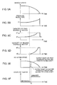
FIG. 2 illustrates the correlation between the oil pressure inside the supply pipe and the capacity of the first hydraulic motor in the hydraulic traveling vehicle according to the first embodiment; -
FIG. 3 illustrates the correlation between the oil pressure inside the supply pipe and the capacity of the second hydraulic motor in the hydraulic traveling vehicle according to the first embodiment; -
FIG. 4 shows correlation diagrams of vehicle speed, hydraulic pressure inside the supply pipe, capacity of the first hydraulic motor, capacity of the second hydraulic motor, rotation speed of the first hydraulic motor and second hydraulic motor, and clutch state versus the elapsed time during acceleration of the hydraulic traveling vehicle according to the first embodiment; -
FIG. 5 shows correlation diagrams of vehicle speed, hydraulic pressure inside the supply pipe, capacity of the first hydraulic motor, capacity of the second hydraulic motor, rotation speed of the first hydraulic motor and second hydraulic motor, and clutch state versus the elapsed time during deceleration of the hydraulic traveling vehicle according to the first embodiment; -
FIG. 6 shows a drive system of a hydraulic traveling vehicle according to a comparative example that illustrates the effect of the hydraulic traveling vehicle of the first embodiment; -
FIG. 7 illustrates the correlation between the oil pressure inside the supply pipe and the capacity of the first hydraulic motor in the hydraulic traveling vehicle according to the comparative example shown inFIG. 6 ; -
FIG. 8 illustrates the correlation between the oil pressure inside the supply pipe and the capacity of the second hydraulic motor in the hydraulic traveling vehicle according to the comparative example shown inFIG. 6 ; -
FIG. 9 illustrates a drive system of a hydraulic traveling vehicle according to the second embodiment of the present invention; -
FIG. 10 illustrates a drive system of a hydraulic traveling vehicle according to the third embodiment of the present invention; -
FIG. 11 illustrates a drive system of a hydraulic traveling vehicle according to the fourth embodiment of the present invention; -
FIG. 12 illustrates a drive system of a hydraulic traveling vehicle according to the fifth embodiment of the present invention; and -
FIG. 13 illustrates a drive system of a hydraulic traveling vehicle according to the sixth embodiment of the present invention. - The preferred embodiments of the present invention will be described below with reference to the appended drawings.
- A configuration of the hydraulic traveling vehicle according to the first embodiment of the present invention will be explained below with reference to
FIG. 1 . - The hydraulic traveling vehicle according to the first embodiment uses a HST traveling system. Thus, in the hydraulic traveling vehicle, a
hydraulic pump 8 is driven by power of anengine 6,hydraulic motors hydraulic pump 8, and drive power generated by thehydraulic motors wheels 2 and causes the vehicle to travel. - More specifically, as shown in
FIG. 1 , the hydraulic traveling vehicle of the first embodiment includes thewheels 2, awheel shaft 4, theengine 6, an accelerator device (not shown in the figure), thehydraulic pump 8, a firsthydraulic motor 10, a secondhydraulic motor 12, afirst pipe 14, asecond pipe 16, supply-discharge pipes first pressure sensor 20a, asecond pressure sensor 20b, aconnection pipe 22, afirst check valve 23, asecond check valve 24, afirst relief valve 25, asecond relief valve 26, adischarge pipe 27, a combiningmechanism 28, atransmission mechanism 30, a forward-rearward switching device 32, and acontrol unit 34. - The
wheel shaft 4 is connected to thewheels 2. More specifically, thewheel shaft 4 extends in the transverse direction of the vehicle, and thewheels 2 are mounted on both ends of thevehicle shaft 4. Thewheels 2 and thewheel shaft 4 rotate integrally when the vehicle travels. - The
engine 6 is connected to thehydraulic pump 8 so that the drive power of theengine 6 is transmitted to thehydraulic pump 8. - The accelerator device (not shown in the figure) is connected to the
engine 6. The accelerator device is operated by an operator. The accelerator device increases or decreases the rotation speed of theengine 6 in response to the increase or decrease of the operation amount of the accelerator device. - The
hydraulic pump 8 is driven by the power of theengine 6 and, when driven, discharges hydraulic oil. Thehydraulic pump 8 is of a variable displacement type and a bidirectional discharge type. Thehydraulic pump 8 has a one-side supply-discharge port 8a and an other-side supply-discharge port 8b. Further, thehydraulic pump 8 changes its own capacity and discharge direction of the hydraulic oil in response to control signals outputted from thecontrol unit 34. Thehydraulic pump 8 receives control signals outputted from thecontrol unit 34 when the vehicle travels forward and discharges the hydraulic oil from the one-side supply-discharge port 8a accordingly and receives control signals outputted from thecontrol unit 34 when the vehicle travels rearward and discharges the hydraulic oil from the other-side supply-discharge port 8b accordingly. - The first
hydraulic motor 10 and the secondhydraulic motor 12 are driven by a hydraulic pressure of the hydraulic oil discharged from thehydraulic pump 8, and thereby generates drive power. The firsthydraulic motor 10 and the secondhydraulic motor 12 are variable displacement hydraulic motors having variable capacity. The firsthydraulic motor 10 has a one-side supply-discharge port 10a and an other-side supply-discharge port 10b. The secondhydraulic motor 12 has a one-side supply-discharge port 12a and an other-side supply-discharge port 12b. The capacity of the firsthydraulic motor 10 is changed by inputting a control signal from thecontrol unit 34 to the firsthydraulic motor 10, and the capacity of the secondhydraulic motor 12 is changed by inputting a control signal from thecontrol unit 34 to the secondhydraulic motor 12. - The
first pipe 14 is connected to the one-side supply-discharge port 8a of thehydraulic pump 8, and thesecond pipe 16 is connected to the other-side supply-discharge port 8b of thehydraulic pump 8. Thefirst pipe 14 is included in the concept of "supply pipe" in accordance with the present invention. - The supply-
discharge pipe 17a, from between the supply-discharge pipes hydraulic pump 8 into thefirst pipe 14 into the one-side supply-discharge port 10a of the firsthydraulic motor 10 and return the hydraulic oil discharged from the one-side supply-discharge port 10a of the firsthydraulic motor 10 to thefirst pipe 14. This supply-discharge pipe 17a is included in the concept of "first introducing pipe" in accordance with the present invention. One end of the supply-discharge pipe 17a is connected to thefirst pipe 14, and the other end of the supply-discharge pipe 17a is connected to the one-side supply-discharge port 10a of the firsthydraulic motor 10. - The other supply-
discharge pipe 17b, from among the supply-discharge pipes hydraulic pump 8 into thesecond pipe 16 into the other-side supply-discharge port 10b of the firsthydraulic motor 10 and return the hydraulic oil discharged from the other-side supply-discharge port 10b of the firsthydraulic motor 10 to thesecond pipe 16. One end of the other supply-discharge pipe 17b is connected to thesecond pipe 16, and the other end of the other supply-discharge pipe 17b is connected to the other-side supply-discharge port 10b of the firsthydraulic motor 10. - The supply-
discharge pipe 18a, from among the supply-discharge pipes hydraulic pump 8 into thefirst pipe 14 into the one-side supply-discharge port 12a of the secondhydraulic motor 12 and return the hydraulic oil discharged from the one-side supply-discharge port 12a of the secondhydraulic motor 12 to thefirst pipe 14. This supply-discharge pipe 18a is included in the concept of "second introducing pipe" in accordance with the present invention. One end of the supply-discharge pipe 18a is connected to thefirst pipe 14, and the other end of the supply-discharge pipe 18a is connected to the one-side supply-discharge port 12a of the secondhydraulic motor 12. - The other supply-
discharge pipe 18b, from among the supply-discharge pipes hydraulic pump 8 into thesecond pipe 16 into the other-side supply-discharge port 12b of the secondhydraulic motor 12 and return the hydraulic oil discharged from the other-side supply-discharge port 12b of the secondhydraulic motor 12 to thesecond pipe 16. One end of the other supply-discharge pipe 18b is connected to thesecond pipe 16, and the other end of the other supply-discharge pipe 18b is connected to the other-side supply-discharge port 12b of the secondhydraulic motor 12. - With such a configuration of pipes, the hydraulic oil can circulate between the
hydraulic pump 8 and bothhydraulic motors discharge port 8a of thehydraulic pump 8, this hydraulic oil is distributed in equal amounts to the supply-discharge pipe 17a and the supply-discharge pipe 18a via thefirst pipe 14. The hydraulic oil flowing in the supply-discharge pipe 17a is introduced into the one-side supply-discharge port 10a of the firsthydraulic motor 10, and the hydraulic oil flowing in the supply-discharge pipe 18a is introduced into the one-side supply-discharge port 12a of the secondhydraulic motor 12. The hydraulic oil discharged from the other-side supply-discharge port 10b of the firsthydraulic motor 10 flows into thesecond pipe 16 via the supply-discharge pipe 17b, and the hydraulic oil discharged from the other-side supply-discharge port 12b of the secondhydraulic motor 12 flows into thesecond pipe 16 via the supply-discharge pipe 18b. The hydraulic oil that has flown in thesecond pipe 16 returns to the other-side supply-discharge port 8b of thehydraulic pump 8. When the hydraulic oil is discharged from the other-side supply-discharge port 8b of thehydraulic pump 8, the hydraulic oil flows in the path reversed with respect to the above-described one. - The
first pressure sensor 20a is connected to thefirst pipe 14, and thesecond pressure sensor 20b is connected to thesecond pipe 16. Thefirst pressure sensor 20a detects a pressure of the hydraulic oil flowing in thefirst pipe 14, and thesecond pressure sensor 20b detects a pressure of the hydraulic oil flowing in thesecond pipe 16. Thesepressure sensors control unit 34. - The
connection pipe 22 connects thefirst pipe 14 and thesecond pipe 16 to each other. Theconnection pipe 22 is provided with thefirst check valve 23 and thesecond check valve 24. A pipe is provided that connects a portion of theconnection pipe 22 located between thefirst check valve 23 and thesecond check valve 24 to thefirst pipe 14 in order to bypass thefirst check valve 23, and thefirst relief valve 25 is provided in this pipe. Further, a pipe is provided that connects a portion of theconnection pipe 22 located between thefirst check valve 23 and thesecond check valve 24 to thesecond pipe 16 in order to bypass thesecond check valve 24, and thesecond relief valve 26 is provided in this pipe. The portion of theconnection pipe 22 that is located between thefirst check valve 23 and thesecond check valve 24 is connected to a hydraulic oil tank T via thedischarge pipe 27. With such a configuration, where a hydraulic pressure inside thefirst pipe 14 becomes higher than a set pressure of thefirst relief valve 25, the hydraulic oil escapes from thefirst pipe 14 into the hydraulic oil tank T via thefirst relief valve 25 and thedischarge pipe 27. Where a hydraulic pressure inside thesecond pipe 16 becomes higher than a set pressure of thesecond relief valve 26, the hydraulic oil escapes from thesecond pipe 16 into the hydraulic oil tank T via thesecond relief valve 26 and thedischarge pipe 27. Therefore, the hydraulic pressure inside thefirst pipe 14 is maintained at a level equal to or less than the set pressure of thefirst relief valve 25, and the hydraulic pressure inside thesecond pipe 16 is maintained at a level equal to or less than the set pressure of thesecond relief valve 26. - The combining
mechanism 28 can combine the drive power generated by the firsthydraulic motor 10 with the drive power generated by the secondhydraulic motor 12. The combiningmechanism 28 is switched between a state in which the combiningmechanism 28 combines the drive power generated by the firsthydraulic motor 10 and the drive power generated by the secondhydraulic motor 12 and a state in which the combiningmechanism 28 does not combine the drive power generated by the firsthydraulic motor 10 and the drive power generated by the secondhydraulic motor 12. The combiningmechanism 28 includes a firstrotating shaft 42, a secondrotating shaft 44, and a clutch 46. - The first
rotating shaft 42 is rotated by the drive power generated by the firsthydraulic motor 10. More specifically, the firstrotating shaft 42 is coaxially connected to an output shaft of the firsthydraulic motor 10 and rotates together with the output shaft of the firsthydraulic motor 10, following the drive of the firsthydraulic motor 10. The firstrotating shaft 42 is connected to thetransmission mechanism 30. - The second
rotating shaft 44 is rotated by the drive power generated by the secondhydraulic motor 12. More specifically, the secondrotating shaft 44 is coaxially connected to an output shaft of the secondhydraulic motor 12 and rotates together with the output shaft of the secondhydraulic motor 12, following the drive of the secondhydraulic motor 12. Further, the secondrotating shaft 44 is disposed coaxially with the firstrotating shaft 42 and rotated in the same rotation direction as that of the firstrotating shaft 42 by the drive power of the secondhydraulic motor 12. - The clutch 46 is provided between the first
rotating shaft 42 and the secondrotating shaft 44. The clutch 46 is included in the concept of "first clutch" in accordance with the present invention. The clutch 46 is automatically switched between an engaged state in which the clutch engages the firstrotating shaft 42 and the secondrotating shaft 44 and a disengaged state in which the clutch disengages the firstrotating shaft 42 and the secondrotating shaft 44 according to the rotation direction and rotation speed of the firstrotating shaft 42 and the secondrotating shaft 44. When the clutch 46 is in the engaged state, the combiningmechanism 28 is in a state of combining the drive powers of the twohydraulic motors mechanism 28 does not combine the drive powers of the twohydraulic motors - For example, when the clutch 46 is a sprag-type one-way clutch (see, for example, Japanese Patent Application Laid-open No.
H5-26264 first engagement portion 47, asecond engagement portion 48, and a plurality of sprags (not shown in the figure) serving as support members for supporting thesecond engagement portion 48 with respect to thefirst engagement portion 47. - The
first engagement portion 47 is joined to the firstrotating shaft 42 so as to rotate integrally with the firstrotating shaft 42. Thesecond engagement portion 48 is joined to the secondrotating shaft 44 so as to rotate integrally with the secondrotating shaft 44. Thesefirst engagement portion 47 and thesecond engagement portion 48 can be rotated in a direction causing the hydraulic traveling vehicle to move forward when the rotation power of the engagement portions is transmitted to thewheels 2 and also in the direction opposite to this rotation direction and such that the hydraulic traveling vehicle moves rearward when the rotation power of the engagement portions is transmitted to thewheels 2. - When the rotation speed of the
second engagement portion 48 in the rotation direction causing the hydraulic traveling vehicle to move forward rises and reaches a rotation speed equal to the rotation speed of thefirst engagement portion 47 in the same rotation direction, the clutch 46 automatically assumes the engaged state. As a result, thefirst engagement portion 47 rotates integrally with thesecond engagement portion 48. When the rotation speed of thesecond engagement portion 48 in the direction causing the hydraulic traveling vehicle to move forward decreases below the rotation speed of thefirst engagement portion 47 in the same rotation direction, the clutch 46 automatically assumes the disengaged state. As a result, thefirst engagement portion 47 idles with respect to thesecond engagement portion 48. Further, when the rotation speed of thefirst engagement portion 47 in the rotation direction causing the hydraulic traveling vehicle to move rearward increases and reaches the rotation speed equal to the rotation speed of thesecond engagement portion 48 in the same rotation direction, the clutch 46 automatically assumes the engaged state. As a result, thesecond engagement portion 48 rotates integrally with thefirst engagement portion 47. When the rotation speed of thefirst engagement portion 47 in the rotation direction causing the hydraulic traveling vehicle to move rearward decreases below the rotation speed of thesecond engagement portion 48 in the same rotation direction, the clutch 46 automatically assumes the disengaged state. As a result, thesecond engagement portion 48 idles with respect to thefirst engagement portion 47. - The
first engagement portion 47 has an outer ring portion (not shown in the figure) disposed coaxially with the firstrotating shaft 42. Thesecond engagement portion 48 has an inner ring portion (not shown in the figure) disposed coaxially with the secondrotating shaft 44. The inner ring portion is provided to be coaxial with the outer ring portion on the inside of the outer ring portion of thefirst engagement portion 47. A plurality of sprags are provided between the outer ring portion of thefirst engagement portion 47 and the inner ring portion of thesecond engagement portion 48 and arranged in the circumferential direction of the outer ring portion and the inner ring portion. These sprags can function as props supporting the inner ring portion with respect to the outer ring portion between the outer ring portion and the inner ring portion. - When the rotation speed of the
second engagement portion 48 in the rotation direction causing the hydraulic traveling vehicle to move forward rises and reaches a rotation speed equal to the rotation speed of thefirst engagement portion 47 in the same rotation direction, the sprags assume a state of connecting thefirst engagement portion 47 with thesecond engagement portion 48 such that prevents thesecond engagement portion 48 from rotating relative to thefirst engagement portion 47. As a result, theengagement portions second engagement portion 48 in the rotation direction causing the hydraulic traveling vehicle to move forward is below the rotation speed of thefirst engagement portion 47 in the same rotation direction, the sprags assume a state in which thesecond engagement portion 48 is allowed to rotate with respect to thefirst engagement portion 47. - More specifically, when the rotation speed of the
second engagement portion 48 in the rotation direction causing the hydraulic traveling vehicle to move forward rises and reaches a rotation speed equal to the rotation speed of thefirst engagement portion 47 in the same rotation direction, in other words, when the inner ring portion of thesecond engagement portion 48 rotates in the same direction relative to the outer ring portion of thefirst engagement portion 47 rotating in the rotation direction causing the vehicle to move forward and the rotation speed of the inner ring portion starts exceeding the rotation speed of the outer ring portion of thefirst engagement portion 47, the outer ring portion of thefirst engagement portion 47 and the inner ring portion of thesecond engagement portion 48 mesh with the sprags. As a result, thefirst engagement portion 47 and thesecond engagement portion 48 rotate integrally. When the rotation speed of thesecond engagement portion 48 in the rotation direction causing the hydraulic traveling vehicle to move forward is below the rotation speed of thefirst engagement portion 47 in the same rotation direction, in other words, when the inner ring portion of thesecond engagement portion 48 rotates in the opposite direction with respect to the outer ring portion of thefirst engagement portion 47 rotating in the rotation direction causing the vehicle to move forward, both thefirst engagement portion 47 and thesecond engagement portion 48 idle with respect to the sprags. As a result, thefirst engagement portion 47 idles with respect to thesecond engagement portion 48. - Further, when the rotation speed of the
second engagement portion 48 in the rotation direction causing the hydraulic traveling vehicle to move rearward rises and reaches a rotation speed equal to the rotation speed of thefirst engagement portion 47 in the same rotation direction, the sprags assume a state of connecting thefirst engagement portion 47 with thesecond engagement portion 48 so as to prevent thesecond engagement portion 48 from rotating relative to thefirst engagement portion 47. As a result, theengagement portions second engagement portion 48 in the rotation direction causing the hydraulic traveling vehicle to move rearward is below the rotation speed of theengagement portion 47 in the same rotation direction, the sprags assume a state in which thesecond engagement portion 48 is allowed to rotate relative to thefirst engagement portion 47. - More specifically, when the rotation speed of the
first engagement portion 47 in the rotation direction causing the hydraulic traveling vehicle to move rearward (rotation direction opposite to the rotation direction causing the vehicle to move forward) rises and reaches the rotation speed equal to the rotation speed of thesecond engagement portion 48 in the same rotation direction, that is, when the outer ring portion of thefirst engagement portion 47 rotates in the same rotation direction relative to the inner ring portion of thesecond engagement portion 48 that rotates in the rotation direction causing the vehicle to move rearward and the rotation speed of the outer ring portion starts exceeding the rotation speed of the inner ring portion of thesecond engagement portion 48, the outer ring portion of thefirst engagement portion 47 and the inner ring portion of thesecond engagement portion 48 mesh with the sprags. As a result, thefirst engagement portion 47 and thesecond engagement portion 48 rotate integrally. When the rotation speed of thefirst engagement portion 47 in the rotation direction causing the hydraulic traveling vehicle to move rearward is below the rotation speed of thesecond engagement portion 48 in the same rotation direction, that is, when the outer ring portion of thefirst engagement portion 47 rotates in the opposite direction relative to the inner ring portion of thesecond engagement portion 48 rotating in the rotation direction causing the vehicle to move rearward, both thefirst engagement portion 47 and thesecond engagement portion 48 idle with respect to the sprags. As a result, thefirst engagement portion 47 idles with respect to thesecond engagement portion 48. - In addition to the above-described sprag-type one-way clutch, for example, a well-known roller-type one-way clutch (see Japanese Patent Application Laid-open No.
H8-338450 - The
transmission mechanism 30 transmits the drive power obtained from the combiningmechanism 28 to thewheel shaft 4 and thereby rotates thewheel shaft 4 and thewheels 2. Thetransmission mechanism 30 is connected to the firstrotating shaft 42 of the combiningmechanism 28 and transmits the drive power from the firstrotating shaft 42 to thewheel shaft 4. Thetransmission mechanism 30 includes afirst gear 49, asecond gear 50, atransmission shaft 51, and a conversion unit (not shown in the figure). - The
first gear 49 is externally fitted onto the firstrotating shaft 42 and fixed thereto in a state of being disposed coaxially with the firstrotating shaft 42. Thefirst gear 49 is an external gear and rotates together with the firstrotating shaft 42. - The
second gear 50 meshes with thefirst gear 49. Further, thesecond gear 50 is joined to one end portion of thetransmission shaft 51 in a state of being disposed coaxially with thetransmission shaft 51. Thesecond gear 50 receives rotation of thefirst gear 49 and thereby rotates together with thetransmission shaft 51. - The
transmission shaft 51 extends in the longitudinal direction of the vehicle. Thesecond gear 50 is joined to one axial end portion of thetransmission shaft 51. Thetransmission shaft 51 transmits from thesecond gear 50 to thewheel shaft 4 the rotation power transmitted from thefirst gear 49 to thesecond gear 50. Thetransmission shaft 51 is supported by bearings (not shown in the figure) so that thetransmission shaft 51 can rotate about the axis thereof. - The conversion unit (not shown in the figure) is connected to the end portion of the
transmission shaft 51 on the side opposite that of the end portion joined to thesecond gear 50. The conversion unit is also connected to thewheel shaft 4. The conversion unit converts the rotation power of thetransmission shaft 51 about the axis thereof into the rotation power about a horizontal axis extending in the transverse direction of the vehicle and applies the converted rotation power to thewheel shaft 4. - The forward-
rearward switching device 32 is configured to be capable of switching between a forward designation state that designates the forward movement of the vehicle and a rearward designation state that designates the rearward movement of the vehicle and, depending on whether the state is the forward designation state or the rearward designation state, outputs to the control unit 34 a signal corresponding to the state thereof. - More specifically, as shown in
FIG. 1 , the forward-rearward switching device 32 has amain body portion 32a and a forward-rearward switching portion 32b. The forward-rearward switching portion 32b is composed of an operation lever operated by the operator and attached to themain body portion 32a so as to enable switching between a forward position for designating forward movement of the vehicle and a rearward position for designating rearward movement of the vehicle. More specifically, the forward-rearward switching portion 32b is attached to themain body portion 32a so that the forward-rearward switching portion can tumble to one side with respect to a neutral position and to the other side that is on the opposite side of the neutral position, thereby assuming a forward position by tumbling to one side from the neutral position and assuming a rearward position by tumbling to the other side from the neutral position. A state in which the forward-rearward switching portion 32b is switched to the forward position corresponds to the forward designation state of the forward-rearward switching device 32, and a state in which the forward-rearward switching portion 32b is switched to the rearward position corresponds to the rearward designation position of the forward-rearward switching device 32. Themain body portion 32a outputs to the control device 34 a first signal that notifies the control device of the forward-rearward switching portion 32b being switched to the forward position when such switching occurs and also outputs to the control device 34 a second signal that notifies the control device of the forward-rearward switching portion 32b being switched to the rearward position when such switching occurs. - The
control device 34 controls a capacity of thehydraulic pump 8, a capacity of the firsthydraulic motor 10, and a capacity of the secondhydraulic motor 12. Thecontrol device 34 controls the capacities of thehydraulic pump 8, the firsthydraulic motor 10, and the secondhydraulic motor 12 on the basis of signals indicating the detection pressure that are sent from thepressure sensors control device 34 switches the discharge direction of the hydraulic oil of thehydraulic pump 8 in response to a signal sent from the forward-rearward switching device 32. More specifically, when a first signal is sent from the forward-rearward switching device 32, thecontrol device 34 causes thehydraulic pump 8 to discharge the hydraulic oil from the onedischarge port 8a, and when the second signal is sent from the forward-rearward switching device 32, thecontrol device 34 causes thehydraulic pump 8 to discharge the hydraulic oil from theother discharge port 8b. - The operation of the hydraulic traveling vehicle according to the first embodiment will be described below.
- In the hydraulic traveling vehicle, the
hydraulic pump 8 is actuated following the drive of theengine 6. In this case, when the forward-rearward switching portion 32b is tumbled to the forward position side by the operator, the hydraulic oil is discharged from the one-side supply-discharge port 8a of thehydraulic pump 8 into thefirst pipe 14. - In this case, the
control unit 34 controls the capacity of the firsthydraulic motor 10 according to the relationship such as shown inFIG. 2 and controls the capacity of the secondhydraulic motor 12 according to the relationship such as shown inFIG. 3 on the basis of pressure inside thefirst pipe 14 detected by thefirst pressure sensor 20a. - In the capacity control of both
hydraulic motors FIG. 2 and FIG. 3 , when the vehicle starts accelerating, the pressure inside thefirst pipe 14 rises, as will be described below, and thecontrol device 34 accordingly sets the capacity of the firsthydraulic motor 10 to a maximum capacity q1max and sets a capacity of the secondhydraulic motor 12 to a maximum capacity q2max. Where the speed of the vehicle increases, the pressure inside thefirst pipe 14 decreases and thecontrol unit 34 accordingly reduces the capacity of the twohydraulic motors - Where a sum total of capacities of the two
hydraulic motors hydraulic pump 8 is denoted by Qp, and a capacity efficiency is denoted by ηv, a rotation speed ω of thehydraulic motors 
- Eq. (1) demonstrates that where the sum total q of capacities of the two
hydraulic motors hydraulic motors hydraulic motors FIG. 2 and FIG. 3 makes it possible to increase the rotation speed of thehydraulic motors - More specifically, when acceleration of the vehicle is started from a state in which the vehicle has been stopped (see
FIG. 4A ), since the inertia force maintaining the vehicle in a stopped state acts upon the vehicle, the rotation speed for the firsthydraulic motor 10 and the secondhydraulic motor 12 is difficult to increase. Therefore, the flow rate of the hydraulic oil that can flow into the twohydraulic motors hydraulic pump 8. As a result, as shown inFIG. 4B , the pressure inside thefirst pipe 14 rises abruptly. Further, since the pressure inside thefirst pipe 14 rises, thecontrol unit 34 sets the capacity of the firsthydraulic motor 10 to the maximum capacity q1max (seeFIG. 2 ), as shown inFIG. 4C , and sets the capacity of the secondhydraulic motor 12 to the maximum capacity q2max (seeFIG. 3 ), as shown inFIG. 4D . As a result, a large torque is obtained from the twohydraulic motors - In this case, the clutch 46 assumes the engaged state (see
FIG. 4F ), and the firstrotating shaft 42 and the secondrotating shaft 44 rotate integrally. As a result, the drive powers of the twohydraulic motors wheel shaft 4 via thetransmission mechanism 30. As a result, thewheels 2 are driven by a high torque when the vehicle accelerates. - Where the vehicle speed then increases and the rotation speed of the
hydraulic motors FIG. 4E , the flow rate of the hydraulic oil that can flow into the twohydraulic motors first pipe 14 gradually decreases as shown inFIG. 4B . When the pressure inside thefirst pipe 14 decreases below a pressure P2 (seeFIG. 3 ), thecontrol unit 34 gradually decreases the capacity of the secondhydraulic motor 12. When the pressure inside thefirst pipe 14 further decreases below a pressure P4 (seeFIG. 2 ), thecontrol unit 34 gradually decreases the capacity of the firsthydraulic motor 10. The pressure P2 is set to a value slightly larger than the pressure P4. - At a point in time t1 at which the pressure inside the
first pipe 14 decreases to a pressure P1 (seeFIG. 4B ), thecontrol device 34 decreases the capacity of the secondhydraulic motor 12 to a minimum capacity q2min = 0, as shown inFIG. 4D . As a result, the secondhydraulic motor 12 stops generating the drive power. The secondhydraulic motor 12 then rotates by inertia, and the rotation speed of the secondhydraulic motor 12 decreases due to the revolution resistance thereof. As a result, the rotation speed (rotation speed) of the secondhydraulic motor 12 and the secondrotating shaft 44 decreases rapidly to zero, as shown inFIG. 4E . The rotation speed of thesecond engagement portion 48 of the clutch 46 accordingly decreases below the rotation speed of thefirst engagement portion 47 that rotates together with the output shaft of the firsthydraulic motor 10 and the firstrotating shaft 42. As a result, thefirst engagement portion 47 and thesecond engagement portion 48 become mutually idle and the clutch 46 is switched from the engaged state to the disengaged state (seeFIG. 4F ). Therefore, the drive power of the secondhydraulic motor 12 is not added to the drive power of the firsthydraulic motor 10 in the combiningmechanism 28, and only the drive power of the firsthydraulic motor 10 is transmitted to thewheel shaft 4 via thetransmission mechanism 30. Thus, thewheels 2 are thereafter driven only by the drive power of the firsthydraulic motor 10. - Where the pressure inside the
first pipe 14 then decreases to the pressure P3 (seeFIG. 2 ), thecontrol device 34 decreases the capacity of the firsthydraulic motor 10 to the minimum capacity q1min. Where the pressure inside thefirst pipe 14 thereafter becomes equal to or less than the pressure P3, thecontrol device 34 maintains the capacity of the firsthydraulic motor 10 at the minimum capacity q1min. Then, the rotation speed of the firsthydraulic motor 10 and the rotation speed of the firstrotating shaft 42 become constant. The vehicle speed thus assumes a constant value. - Where the vehicle decelerates from a state of running at a constant speed (see
FIG. 5A ), the rotation speed of thewheels 2 and thewheel shaft 4 decreases and the rotation speed of the firstrotating shaft 42 and the firsthydraulic motor 10 decreases accordingly (seeFIG. 5E ). - In this case, the flow rate of the hydraulic oil that can flow into the first
hydraulic motor 10 decreases and the pressure inside thefirst pipe 14 gradually increases following this decrease in flow rate (seeFIG. 5B ). Where the pressure inside thefirst pipe 14 exceeds the pressure P3 (seeFIG. 2 ), thecontrol unit 34 gradually increases the capacity of the first hydraulic motor 10 (seeFIG. 5C ). Where the pressure inside thefirst pipe 14 further increases above the pressure P1 (seeFIG. 3 ), thecontrol device 34 gradually increases the capacity of the second hydraulic motor 12 (seeFIG. 5D ). Since the capacity of the secondhydraulic motor 12 increases, the secondhydraulic motor 12 starts rotating and the rotation speed of the output shaft of the secondhydraulic motor 12 and the secondrotating shaft 44 rapidly increases as shown inFIG. 5E . As a result, the rotation speed of thesecond engagement portion 48 of the clutch 46 also rapidly increases. Where the rotation speed of thesecond engagement portion 48 reaches the rotation speed equal to the rotation speed of thefirst engagement portion 47, thefirst engagement portion 47 and thesecond engagement portion 48 rotate integrally, and the clutch 46 is switched from the disengaged state to the engaged state (seeFIG. 5F ). - Where the pressure in the
first pipe 14 then rises to pressure P4 (seeFIG. 2 ), thecontrol device 34 increases the capacity of the firsthydraulic motor 10 to the maximum capacity q1max and maintains the capacity. Where the pressure in thefirst pipe 14 further rises to pressure P2 (seeFIG. 3 ), thecontrol device 34 increases the capacity of the secondhydraulic motor 12 to the maximum capacity q2max and maintains the capacity. Where the vehicle then stops traveling and the vehicle speed becomes zero, the drive of thehydraulic pump 8 is stopped. As a result, no hydraulic oil is discharged from thehydraulic pump 8 and therefore the pressure inside thefirst pipe 14 drops to zero. As the pressure inside thefirst pipe 14 decreases, thecontrol device 34 decreases the capacity of the firsthydraulic motor 10 to the minimum capacity q1min and decreases the capacity of the secondhydraulic motor 10 to the minimum capacity q2min = 0. - As described hereinabove, in the first embodiment, when the capacity control is performed to increase the capacity of the second
hydraulic motor 12 from zero in a state in which the firsthydraulic motor 10 operates and the firstrotating shaft 42 and thefirst engagement portion 47 of the clutch 46 rotate at a predetermined rotation speed when the vehicle decelerates and in a state in which thefirst engagement portion 47 idles with respect to thesecond engagement portion 48, if the rotation speed of the secondhydraulic motor 12 rises and the rotation speed of the secondrotating shaft 44 and thesecond engagement portion 48 reaches a rotation speed equal to the rotation speed of thefirst engagement portion 47, the clutch 46 assumes the engaged state and therefore thefirst engagement portion 47 and thesecond engagement portion 48 rotate integrally. Since the rotation speed of thefirst engagement portion 47 is equal to the rotation speed of thesecond engagement portion 48 when the clutch 46 is in the engaged state, occurrence of shocks during coupling of the clutch 46 that are caused by the difference in rotation speed between theengagement portions - Further, in the first embodiment, when the capacity control is performed to decrease the capacity of the second
hydraulic motor 12 to zero in a state in which the firsthydraulic motor 10 and the secondhydraulic motor 12 operate and thefirst engagement portion 47 and thesecond engagement portion 48 of the clutch 46 rotate integrally as the vehicle accelerates, if the rotation speed of the secondhydraulic motor 12 decreases and the rotation speed of the secondrotating shaft 44 and thesecond engagement portion 48 decreases below the rotation speed of thefirst engagement portion 47, the clutch 46 assumes a disengaged state and therefore thefirst engagement portion 47 idles with respect to thesecond engagement portion 48. When the clutch 46 is in the disengaged state, since the capacity of the secondhydraulic motor 12 has already decreased, the secondhydraulic motor 12 is prevented from over-rotating. As a result, breakage of the secondhydraulic motor 12 caused by over-rotation of the secondhydraulic motor 12 can be prevented. Therefore, in the first embodiment, it is possible to prevent breakage of the secondhydraulic motor 12, occurrence of shocks, and damage of the clutch 46 caused by engagement and disengagement of the clutch 46 in a hydraulic traveling vehicle that is driven by drive power of a plurality ofhydraulic motors - In the first embodiment, the clutch 46 is engaged and disengaged by using a relative rotation speed difference between the
first engagement portion 47 and thesecond engagement portion 48. Therefore, by contrast with the conventional configuration in which a clutch is engaged and disengaged by inputting control signals to the clutch from the outside, a lag from the instant at which the rising rotation speed of the secondhydraulic motor 12 and secondrotating shaft 44 reaches a rotation speed equal to the rotation speed of the firsthydraulic motor 10 and firstrotating shaft 42 to the instant at which the clutch 46 actually assumes the engaged state and a lag from the instant at which the rotation speed of the secondhydraulic motor 12 and secondrotating shaft 44 decreases below the rotation speed of the firsthydraulic motor 10 and firstrotating shaft 42 to the instant at which the clutch 46 actually assumes the disengaged state are extremely small. As a result, breakage of the secondhydraulic motor 12, occurrence of shocks, and damage of the clutch 46 caused by such lags can be reliably prevented. - Further, in the first embodiment, since the supply-
discharge pipes first pipe 14 connected on the one-side supply-discharge port 8a of thehydraulic pump 8, the hydraulic oil discharged from thehydraulic pump 8 into thefirst pipe 14 when the vehicle moves forward is naturally distributed in equal amounts to the supply-discharge pipe 17a connected to the firsthydraulic motor 10 and the supply-discharge pipe 18a connected to the secondhydraulic motor 12. As a result, the rotation speed of the firsthydraulic motor 10 is easily synchronized with the rotation speed of the secondhydraulic motor 12. - A configuration such as that of a comparative example shown in
FIG. 6 can be also considered as a configuration of a hydraulic traveling vehicle in which drive power of the firsthydraulic motor 10 and drive power of the secondhydraulic motor 12 are combined and the combined power is transmitted to thewheel shaft 4. More specifically, in the comparative example, the firstrotating shaft 42 connected to the firsthydraulic motor 10 and the secondrotating shaft 44 connected to the secondhydraulic motor 12 are separated in the transverse direction of the vehicle and disposed parallel to each other. Further, in the vehicle of this comparative example, agear box 100 is provided for combining drive power of the firsthydraulic motor 10 to be transmitted to the firstrotating shaft 42 and drive power of the secondhydraulic motor 12 to be transmitted to the secondrotating shaft 44 and transmitting the combined drive power to thetransmission shaft 51. Thegear box 100 has afirst transmission gear 101, asecond transmission gear 102, and a combininggear 103. - The
first transmission gear 101 is disposed coaxially with the firstrotating shaft 42, joined to the firstrotating shaft 42, and rotates integrally with the firstrotating shaft 42. Thesecond transmission gear 102 is disposed coaxially with the secondrotating shaft 44, joined to the secondrotating shaft 44, and rotates integrally with the secondrotating shaft 44. The combininggear 103 is provided between thefirst transmission gear 101 and thesecond transmission gear 102 and meshes with these two transmission gears 101, 102. The combininggear 103 is disposed coaxially with thetransmission shaft 51 and joined to thetransmission shaft 51. - Because of such configuration, in the hydraulic traveling vehicle of the comparative example, drive power of the first
hydraulic motor 10 is transmitted from thefirst transmission gear 101 to the combininggear 103, and drive power of the secondhydraulic motor 12 is transmitted from thesecond transmission gear 102 to the combininggear 103. As a result, drive power of thehydraulic motor 10 is combined with drive power of thehydraulic motor 12, and the combined drive power is transmitted from the combininggear 103 to thewheel shaft 4 via thetransmission shaft 51. In the comparative example, the capacity control of thehydraulic motors hydraulic motor 10 is conducted according to the relationship shown inFIG. 2 , and the capacity control of the secondhydraulic motor 12 is conducted according to the relationship shown inFIG. 3 . - However, in the comparative example, where the vehicle speed rises and the capacity of the second
hydraulic motor 12 becomes zero, the secondhydraulic motor 12 does not output dive power and the secondhydraulic motor 12 becomes a load for the firsthydraulic motor 10. - More specifically, the first
hydraulic motor 10 and the secondhydraulic motor 12 are connected to each other by the firstrotating shaft 42, the secondrotating shaft 44, and thegears 101 to 103. Therefore, in a state in which the firsthydraulic motor 10 operates and the secondhydraulic motor 12 does not output drive power, the secondhydraulic motor 12 operates by receiving drive power transmitted from the firsthydraulic motor 10 via the firstrotating shaft 42, the secondrotating shaft 44, and thegears 101 to 103. As a result, rotation resistance of the secondhydraulic motor 12 acts as a load for the firsthydraulic motor 10. - More specifically, where a rotation resistance torque of the second
hydraulic motor 12 is denoted by Tm2, an input torque of thewheel shaft 4 necessary to maintain the vehicle speed is denoted by Ta, a speed reduction ratio in transmission of rotation from thefirst transmission gear 101 and thesecond transmission gear 102 to the combininggear 103 is denoted by ib, and a mechanical efficiency of thegear box 100 is denoted by ηg, an output torque Tm1 of the firsthydraulic motor 10 necessary to maintain the vehicle speed in a state in which the capacity of the secondhydraulic motor 12 is made zero and no drive power is outputted from thehydraulic motor 12 can be represented by the following Eq. (2).
- As follows from this Eq. (2), in the comparative example, the necessary output torque Tm1 of the first
hydraulic motor 10 includes an element of rotation resistance torque Tm2 of the secondhydraulic motor 12 in addition to the element of torque Ta/ib necessary to drive thewheel shaft 4. Therefore, the necessary output torque of the firsthydraulic motor 10 increases. Where the necessary output torque of the firsthydraulic motor 10 increases, the power of theengine 6, which is the power source of the firsthydraulic motor 10, increases. As a result, fuel consumption is degraded. - By contrast, in the first embodiment, when the capacity of the second
hydraulic motor 12 is reduced to zero, the clutch 46 assumes the disengaged state and thereby thefirst engagement portion 47 is idle with respect to thesecond engagement portion 48. Therefore, the rotation resistance torque of the secondhydraulic motor 12 is not transmitted to the firsthydraulic motor 10. Therefore, the necessary output torque Tm1 of the firsthydraulic motor 10 in the first embodiment can be represented by the following Eq. (3) .
- As follows from this Eq. (3), in the first embodiment, the necessary output torque Tm1 of the first
hydraulic motor 10 is reduced by comparison with the necessary output torque Tm1 of the firsthydraulic motor 10 in the comparative example by an amount attributed to the rotation resistance torque of the secondhydraulic motor 12. Therefore, the power of theengine 6 can be reduced. As a result, fuel consumption can be improved. - In the configuration according to the comparative example, it is also possible to control the capacity of the first
hydraulic motor 10 and the capacity of the secondhydraulic motor 12 with respect to the pressure inside thefirst pipe 14 according to the relationship shown inFIG. 7 . With such control method, the capacity of the firsthydraulic motor 10 and the capacity of the secondhydraulic motor 12 can be controlled in the same manner. With this control method, a sum total qsum of the minimum capacity of the firsthydraulic motor 10 and the minimum capacity of the secondhydraulic motor 12 can be represented by the following Eq. (4).
where Q stands for a discharge amount of thehydraulic pump 8, ηv - a volume efficiency, Vmax - a maximum speed of the vehicle, and R - a diameter of thewheel 2. - Where the minimum capacity of the
hydraulic motors hydraulic motors FIG. 7 is denoted by q5, the relationship represented by the following Eq. (5) is valid.
- Thus, the minimum capacity q5 of the
hydraulic motors hydraulic motors FIG. 7 assumes a value that is half the minimum capacity q1min of the firsthydraulic motor 10 in the first embodiment in which the capacity control of thehydraulic motors FIG. 2 and FIG. 3 . - The relationship between a total efficiency ηt of the
hydraulic motors hydraulic motors FIG. 8 . In the comparative example in which the capacity control of bothhydraulic motors FIG. 7 , the minimum capacity q5 of thehydraulic motors hydraulic motor 10 of the first embodiment, as described hereinabove. Therefore, the total efficiency of thehydraulic motors hydraulic motor 10 in the first embodiment, as suggested by the relationship shown inFIG. 8 . As a result, in the comparative example, the efficiency of power transmission to thewheel shaft 4 decreases and accordingly larger power should be outputted from theengine 6. As a result, fuel consumption is degraded. - By contrast, in the first embodiment, the minimum capacity q1min of the first
hydraulic motor 10 increases over the minimum capacity q5 of thehydraulic motors hydraulic motor 10 improves over the total efficiency of thehydraulic motors wheel shaft 4 increases and the power outputted from theengine 6 can be decreased accordingly. As a result, fuel consumption is improved. - The configuration of the hydraulic traveling vehicle according to the second embodiment of the present invention will be described below with reference to
FIG. 9 . - In the hydraulic traveling vehicle of the second embodiment, the combining
mechanism 28 includes a second clutch 52 in addition to a first clutch 46a, and when the vehicle moves rearward, drive power of the firsthydraulic motor 10 and drive power of the secondhydraulic motor 12 are combined via thesecond clutch 52. - More specifically, the first clutch 46a is configured similarly to the clutch 46 of the first embodiment.
- The second clutch 52 is provided so as to surround the first clutch 46a and straddle between the first
rotating shaft 42 and the secondrotating shaft 44. The second clutch 52 receives an input of an instruction signal from thecontrol device 34 and is accordingly switched between the engaged state in which the firstrotating shaft 42 and the secondrotating shaft 44 are connected and the disengaged state in which the firstrotating shaft 42 and the secondrotating shaft 44 are disconnected. When the second clutch 52 is in the engaged state, the combiningmechanism 28 is in a state of combining drive powers of bothhydraulic motors third engagement portion 53, afourth engagement portion 54, a one-side support portion 55, an other-side support portion 56, and adrive unit 57. - The
third engagement portion 53 and thefourth engagement portion 54 are annular clutch plates disposed on the outside of the first clutch 46a so as to surround the first clutch 46a. Thesethird engagement portion 53 andfourth engagement portion 54 are disposed coaxially. Theengagement portions engagement portions - The one-
side support portion 55 is provided at the firstrotating shaft 42. This one-side support portion 55 supports thethird engagement portion 53 so that thethird engagement portion 53 is coaxial with the firstrotating shaft 42. The other-side support portion 56 is provided at the secondrotating shaft 44. The other-side support portion 56 supports thefourth engagement portion 54 so that thefourth engagement portion 54 is coaxial with the secondrotating shaft 44. Further, the other-side support portion 56 supports thefourth engagement portion 54 so that thefourth engagement portion 54 can move in the axial direction thereof. As a result, thefourth engagement portion 54 can be brought into contact with and separated from thethird engagement portion 53. - The
drive unit 57 is provided at the other-side support portion 56. Thedrive unit 57 receives an input of an instruction signal from thecontrol device 34 and moves thefourth engagement portion 54 between a contact position and a withdrawal position accordingly. The contact position is a position in which thefourth engagement portion 54 is in contact with thethird engagement portion 53. The withdrawal position is a position in which thefourth engagement portion 54 is withdrawn from thethird engagement portion 53. - More specifically, in the second embodiment, the
control device 34 sends a disengaged state instruction signal for instructing the second clutch 52 to assume the disengaged state when the forward-rearward switching portion 32b is switched to the forward position, and sends an engaged state instruction signal for instructing the second clutch 52 to assume the engaged state when the forward-rearward switching portion 32b is switched to the rearward position. More specifically, when a first signal notifying that the forward-rearward switching portion 32b was switched to the forward position has been sent from themain body portion 32a of the forward-rearward switching device 32, thecontrol device 34 sends the disengaged state instruction signal to thedrive unit 57 of the second clutch 52, and when a second signal notifying that the forward-rearward switching portion 32b was switched to the rearward position has been sent from themain body portion 32a of the forward-rearward switching device 32, thecontrol device 34 sends the engaged state instruction signal to thedrive unit 57 of thesecond clutch 52. - When the disengaged state instruction signal is input to the
drive unit 57, thedrive unit 57 moves thefourth engagement portion 54 to the withdrawal position. As a result, thethird engagement portion 53 and thefourth engagement portion 54 are disengaged from each other. When the engaged state instruction signal is input to thedrive unit 57, thedrive unit 57 moves thefourth engagement portion 54 to the contact position. As a result, thethird engagement portion 53 and thefourth engagement portion 54 are engaged with each other. - When the forward-
rearward switching portion 32b is switched to the rearward position and the vehicle moves rearward accordingly, thecontrol device 34 causes thehydraulic pump 8 to discharge the hydraulic oil from the other-side supply-discharge port 8b into thesecond pipe 16. The hydraulic oil discharged into thesecond pipe 16 is introduced into the other-side supply-discharge port 10b of the firsthydraulic motor 10 via the supply-discharge pipe 17b and also introduced into the other-side supply-discharge port 12b of the secondhydraulic motor 12 via the supply-discharge pipe 18b. As a result, the firsthydraulic motor 10 and the secondhydraulic motor 12 rotate in the opposite direction. - When the rotation speed (rotation speed of the first
rotating shaft 42 and the first engagement portion 47) of the firsthydraulic motor 10 increases from a state in which the rotation speed of the firsthydraulic motor 10 is lower than the rotation speed of the secondhydraulic motor 12 and reaches the rotation speed equal to the rotation speed (rotation speed of the secondrotating shaft 44 and the second engagement portion 48) of the secondhydraulic motor 12, the first clutch 46a assumes the engaged state. In this case, thefirst engagement portion 47 and thesecond engagement portion 48 rotate integrally. When the rotation speed (rotation speed of the firstrotating shaft 42 and the first engagement portion 47) of the firsthydraulic motor 10 is below the rotation speed (rotation speed of the secondrotating shaft 44 and the second engagement portion 48) of the secondhydraulic motor 12, the first clutch 46a assumes the disengaged state. In this case, thefirst engagement portion 47 idles with respect to thesecond engagement portion 48. Therefore, when the vehicle moves rearward, drive power of the secondhydraulic motor 12 cannot be effectively used in the transmission path of power via the first clutch 46a. Thus, when the rotation speed of the secondhydraulic motor 12 is higher than the rotation speed of the firsthydraulic motor 10, since the first clutch 46a assumes the disengaged state, the drive power of the secondhydraulic motor 12 cannot be transmitted to thetransmission mechanism 30 via the first clutch 46a. Therefore, when power is transmitted via the first clutch 46a, the secondhydraulic motor 12 cannot be used as the main motor. However, in the second embodiment, the second clutch 52 assumes the engaged state when the vehicle moves rearward. As a result, the drive power of the secondhydraulic motor 12 is transmitted to the firstrotating shaft 42 via the second clutch 52 and therefore this drive power can be transmitted to thewheel shaft 4 via thetransmission mechanism 30. As a result, the secondhydraulic motor 12 can be used as the main motor. - Other features and operations of the hydraulic traveling vehicle according to the second embodiment are similar to those of the first embodiment.
- Where the first clutch 46a is configured so that the
second engagement portion 48 idles with respect to thefirst engagement portion 47 when thetransmission mechanism 30 is connected to the firstrotating shaft 42 and the rotation speed of thefirst engagement portion 47 of the first clutch 46a in the rotation direction causing the vehicle to move rearward is below the rotation speed of thesecond engagement portion 48 in the same rotation direction, as described hereinabove, when the rotation speed of the secondhydraulic motor 12 is higher than the rotation speed of the firsthydraulic motor 10 as the vehicle moves rearward, the drive power of the secondhydraulic motor 12 cannot be transmitted to thetransmission mechanism 30 via the first clutch 46a. However, in the second embodiment, since the second clutch 52 assumes the engaged state when the vehicle moves rearward, the drive power of the secondhydraulic motor 12 can be transmitted from the secondrotating shaft 44 to thetransmission mechanism 30 via the second clutch 52 and the firstrotating shaft 42. Therefore, the drive power of the secondhydraulic motor 12 can be transmitted to thewheel shaft 4 when the vehicle moves rearward. As a result, the vehicle can be moved rearward by the drive power which is a combination of the drive power of the firsthydraulic motor 10 and the drive power of the secondhydraulic motor 12. When the vehicle moves forward, the second clutch 52 is in the disengaged state and therefore the effect similar to that of the first embodiment can be obtained by engaging and disengaging the first clutch 46a. - The configuration of the hydraulic traveling vehicle according to the third embodiment of the present invention will be described below with reference to
FIG. 10 . - In the hydraulic traveling vehicle according to the third embodiment, the
transmission mechanism 30 includes areducer 60 that reduces the drive power obtained from the combiningmechanism 28 at a predetermined high reduction ratio and at a low reduction ratio that is a speed reduction ratio lower than the high reduction ratio, and thetransmission mechanism 30 can transmit the drive power reduced at the high reduction ratio or low reduction ratio selected by the operator to thewheel shaft 4. - More specifically, the
reducer 60 provided in thetransmission mechanism 30 includes afirst gear device 61 for performing speed reduction at the low reduction ratio and asecond gear device 62 for performing speed reduction at the high reduction ratio. - The
first gear device 61 is provided at the firstrotating shaft 42. Thefirst gear device 61 reduces the rotation speed of the firstrotating shaft 42 at the low reduction ratio. Thefirst gear device 61 has a low-reductionmain drive gear 61a, a low-reduction drivengear 61b, aconnection shaft 61c, a low-reductionintermediate gear 61d, and a low-reduction transmission gear 61e. Thegears - The low-reduction
main drive gear 61a is externally fitted on and fixed to the firstrotating shaft 42 in a state of being disposed coaxially with the firstrotating shaft 42. The low-reductionmain drive gear 61a rotates together with the firstrotating shaft 42. - The low-reduction driven
gear 61b meshes with the low-reductionmain drive gear 61a and rotates by receiving a rotation force of the low-reductionmain drive gear 61a. The number of teeth of the low-reduction drivengear 61b is slightly larger than the number of teeth of the low-reductionmain drive gear 61a and such that makes it possible to reduce the rotation speed of the low-reductionmain drive gear 61a at a desired low reduction ratio. Thus, speed reduction is performed at a low reduction ratio when rotation drive is transmitted from the low-reductionmain drive gear 61a to the low-reduction drivengear 61b. - The low-reduction
intermediate gear 61d is disposed coaxially with the low-reduction drivengear 61b and connected to the low-reduction drivengear 61b by theconnection shaft 61c. As a result, the low-reduction drivengear 61b,connection shaft 61c, and low-reductionintermediate gear 61d rotate integrally about the same axis. - The low-
reduction transmission gear 61e meshes with the low-reductionintermediate gear 61d and rotates by receiving a rotation force of the low-reductionintermediate gear 61d. The low-reduction transmission gear 61e is disposed to be coaxial with atransmission shaft 63a of the below-describedtransmission unit 63. The low-reduction transmission gear 61e is provided with a through hole (not shown in the figure) that passes through the low-reduction transmission gear 61e in the axial direction thereof. The below-describedtransmission shaft 63a is inserted into the through hole. - The
second gear device 62 is provided at the firstrotating shaft 42. Thesecond gear device 62 reduces the rotation speed of the firstrotating shaft 42 at the high reduction ratio. Thesecond gear device 62 has a high-reductionmain drive gear 62a, a high-reduction drivengear 62b, aconnection shaft 62c, a high-reductionintermediate gear 62d, and a high-reduction transmission gear 62e. Thegears - The high-reduction
main drive gear 62a is externally fitted on and fixed to the firstrotating shaft 42 in a state of being disposed coaxially with the firstrotating shaft 42. The high-reductionmain drive gear 62a rotates together with the firstrotating shaft 42. - The high-reduction driven
gear 62b meshes with the high-reductionmain drive gear 62a and rotates by receiving a rotation force of the high-reductionmain drive gear 62a. The number of teeth of the high-reduction drivengear 62b is larger than the number of teeth of the high-reductionmain drive gear 62a and such that makes it possible to reduce the rotation speed of the high-reductionmain drive gear 62a at a desired high reduction ratio. Thus, speed reduction is performed at a high reduction ratio when the rotation drive is transmitted from the high-reductionmain drive gear 62a to the high-reduction drivengear 62b. The ratio of the number of teeth of the high-reduction drivengear 62b to the number of teeth of the high-reductionmain drive gear 62a is larger than the ratio of the number of teeth of the low-reduction drivengear 61b to the number of teeth of the low-reductionmain drive gear 61a. As a result, the speed reduction ratio at which the rotation power is transmitted from the high-reductionmain drive gear 62a to the high-reduction drivengear 62b is higher than the speed reduction ratio at which the rotation power is transmitted from the low-reductionmain drive gear 61a to the low-reduction drivengear 61b. - The configurations of the
connection shaft 62c, high-reductionintermediate gear 62d, and high-reduction transmission gear 62e are similar to the configurations of the above-describedconnection shaft 6 1 c, low-reductionintermediate gear 6 1 d, and low-reduction transmission gear 61e. As a result, the rotation power of the high-reduction drivengear 62b is transmitted to thetransmission shaft 63 a of the below-describedtransmission unit 63 via theconnection shaft 62c, high-reductionintermediate gear 62d, and high-reduction transmission gear 62e. The high-reduction transmission gear 62e is disposed coaxially with thetransmission shaft 63a and so as to be separated from the low-reduction transmission gear 6 1 e in the axial direction thereof. The high-reduction transmission gear 62e is provided with a through hole (not shown in the figure) that passes through the high-reduction transmission gear 62e in the axial direction thereof. The below-describedtransmission shaft 63a is inserted into the through hole. - Further, the
transmission mechanism 30 has thetransmission unit 63. Thetransmission unit 63 is switched between a high-reduction transmission state and a low-reduction transmission state by inputting an instruction signal from the below-described reductionratio switching device 66. The high-reduction transmission state is a state in which the drive power reduced at a high reduction ratio by thereducer 30 is transmitted to thewheel shaft 4. The low-reduction transmission state is a state in which the drive power reduced at a low reduction ratio by thereducer 30 is transmitted to thewheel shaft 4. - More specifically, the
transmission unit 63 has thetransmission shaft 63a, ashift fork 63b as a joining member, and a shiftfork drive unit 63c. - The
transmission shaft 63a serves to transmit the drive power reduced by thereducer 30 to thewheel shaft 4. As describes above, thetransmission shaft 63a is inserted into the through hole of the low-reduction transmission gear 61 e and also inserted into the through hole of the high-reduction transmission gear 62e. - The
shift fork 63b is provided in a portion of thetransmission shaft 63a positioned between the low-reduction transmission gear 61e and the high-reduction transmission gear 62e. Theshift fork 63b joins either of the low-reduction transmission gear 61e and the high-reduction transmission gear 62e to thetransmission shaft 63a. By moving to the low-reduction transmission position on the low-reduction transmission gear 61e side along thetransmission shaft 63a, theshift fork 63b connects the low-reduction transmission gear 61e to thetransmission shaft 63a, and by moving to the high-reduction transmission position on the high-reduction transmission gear 62e side along thetransmission shaft 63a, theshift fork 63b connects the high-reduction transmission gear 62e to thetransmission shaft 63a. - The shift
fork drive unit 63c has, for example, an air cylinder, receives an instruction signal outputted from the below-described reductionratio switching device 66, and moves theshift fork 63b by air pressure between the low-reduction transmission position and the high-reduction transmission position accordingly. - The end portion of the
transmission shaft 63a on the side opposite that of the transmission gears 61e, 62e is connected to thewheel shaft 4, with a conversion unit (not shown in the figure) being interposed therebetween. The conversion unit (not shown in the figure) is similar to the conversion unit described in the first embodiment. The conversion unit converts the rotation power of thetransmission shaft 63a into the power of rotation about a horizontal axis extending in the transverse direction of the vehicle, and transmits the converted rotation power to thewheel shaft 4. As a result, when thetransmission shaft 63a is connected by theshift fork 63b to the low-reduction transmission gear 61e, the drive power reduced at the low reduction ratio in thefirst gear device 61 is transmitted to thewheel shaft 4 via thetransmission shaft 63a and the conversion unit. When thetransmission shaft 63a is connected by theshift fork 63b to the high-reduction transmission gear 62e, the drive power reduced at the high reduction ratio in thesecond gear device 62 is transmitted to thewheel shaft 4 via thetransmission shaft 63a and the conversion unit. - The hydraulic traveling vehicle of the third embodiment is also provided with a reduction
ratio switching device 66. The reductionratio switching device 66 has amain body portion 66a and a reductionratio switching unit 66b. The reductionratio switching device 66 outputs an instruction signal to the shiftfork drive unit 63c when the reductionratio switching unit 66b is switched to the high-reduction designation position or low-reduction designation position. - More specifically, the reduction
ratio switching unit 66b is composed of an operation lever operated by the operator and mounted on themain body portion 66a to enable switching between the high-reduction designation position and low-reduction designation position. The high-reduction designation position is a position for designating that the drive power reduced at the high reduction ratio by thereducer 30 be transmitted to thewheel shaft 4, and the low-reduction designation position is a position for designating that the drive power reduced at the low reduction ratio by thereducer 30 be transmitted to thewheel shaft 4. The reductionratio switching unit 66b is mounted on themain body portion 32a so that the reduction ratio switching unit can be thrown to one side and to the other side (opposite to the one side) with respect to a neutral position. When the reductionratio switching unit 66b is thrown to one side from the neutral position, the reductionratio switching unit 66b assumes the high-reduction designation position, and when the reductionratio switching unit 66b is thrown to the other side from the neutral position, the reductionratio switching unit 66b assumes the low-reduction designation position. When the low-reductionratio switching unit 66b is switched to the high-reduction designation position, themain body portion 66a outputs to the shiftfork drive unit 63c of thetransmission unit 63 a high-reduction instruction signal for instructing thetransmission unit 63 to assume the high-reduction state, and when the low-reductionratio switching unit 66b is switched to the low-reduction designation position, themain body portion 66a outputs to the shiftfork drive unit 63c of thetransmission unit 63 a low-reduction instruction signal for instructing thetransmission unit 63 to assume the low-reduction state. The shiftfork drive unit 63c receives the high-reduction instruction signal and thereby moves theshift fork 63b to the high-reduction transmission position, or receives the low-reduction instruction signal and thereby moves theshift fork 63b to the low-reduction transmission position. - Other features and operations of the hydraulic traveling vehicle according to the third embodiment are similar to those of the first embodiment.
- As described hereinabove, in the third embodiment, the operator can select a high reduction ratio or a low reduction ratio by operating the reduction
ratio switching unit 66b, and the drive power reduced by thereducer 30 at the selected reduction ratio can be transmitted to thewheel shaft 4. As a result, the operator can select either of the high reduction ratio and the low reduction ratio and cause the vehicle to travel at the selected reduction ratio. - The configuration of the hydraulic traveling vehicle according to the fourth embodiment of the present invention will be described below with reference to
FIG. 11 . - In the hydraulic traveling vehicle of the fourth embodiment, the
second gear device 62 of thereducer 60 of thetransmission mechanism 30 is provided at the secondrotating shaft 44. - More specifically, the high-reduction
main drive gear 62a of thesecond gear device 62 is provided at the secondrotating shaft 44. The high-reductionmain drive gear 62a is externally fitted on and fixed to the secondrotating shaft 44 in a state of being disposed coaxially with the secondrotating shaft 44. The high-reductionmain drive gear 62a rotates together with the secondrotating shaft 44. - Further, in the fourth embodiment, where the
control device 34 decreases the capacity of the secondhydraulic motor 12 as the vehicle speed rises, and the rotation speed of the secondhydraulic motor 12 and the secondrotating shaft 44 is thereby decreased, the rotation speed of the high-reductionmain drive gear 62a decreases. Further, the rotation speed of thesecond engagement portion 48 of the clutch 46 in the rotation direction causing the vehicle to move forward decreases below the rotation speed of thefirst engagement portion 47 in the same rotation direction, the clutch 46 is thereby disengaged, and thefirst engagement portion 47 idles with respect to thesecond engagement portion 48. Where the capacity of the secondhydraulic motor 12 is thereafter reduced to zero and the drive of the secondhydraulic motor 12 stops, the high-reductionmain drive gear 62a stops rotating. As a result, drive of thesecond gear device 62 is stopped. - Other features and operations of the hydraulic traveling vehicle according to the fourth embodiment are similar to those of the third embodiment.
- As described hereinabove, in the fourth embodiment, after the
first engagement portion 47 of the clutch 46 becomes idle with respect to thesecond engagement portion 48, drive of thesecond gear device 62 stops following the actuation stop of the secondhydraulic motor 12, secondrotating shaft 44, andsecond engagement portion 48. As a result, subsequent idle loss of thesecond gear device 62 can be prevented and degradation of fuel consumption can be inhibited. - The configuration of the hydraulic traveling vehicle according to the fifth embodiment of the present invention will be described below with reference to
FIG. 12 . - The hydraulic traveling vehicle according to the fifth embodiment has a configuration obtained by adding the
transmission mechanism 30 having thereducer 60 similar to that of the fourth embodiment to the configuration of the hydraulic traveling vehicle provided with the combiningmechanism 28 having the first clutch 46a and the second clutch 52 according to the second embodiment. - More specifically, in the fifth embodiment, the low-reduction
main drive gear 61a of thefirst gear device 61 of thereducer 60 is mounted on a portion of the firstrotating shaft 42 that is positioned on the firsthydraulic motor 10 side with respect to a portion where the one-side support portion 55 of the second clutch 52 is provided. Further, the high-reductionmain drive gear 62a of thesecond gear device 62 of thereducer 60 is mounted on a portion of the secondrotating shaft 44 that is positioned on the secondhydraulic motor 12 side with respect to a portion where the other-side support portion 56 of the second clutch 52 is provided. - Other features of the hydraulic traveling vehicle according to the fifth embodiment are similar to those of the hydraulic traveling vehicle according to the second embodiment and those of the hydraulic traveling vehicle according to the fourth embodiment.
- The operation of portions of the hydraulic traveling vehicle according to the fifth embodiment that relate to the combining
mechanism 28 is similar to that of the second embodiment, and the operation of portions relating to thetransmission mechanism 30 is similar to that of the fourth embodiment. Therefore, in the fifth embodiment, the drive power of the secondhydraulic motor 12 can be transmitted to thewheel shaft 4 when the vehicle moves rearward. As a result, the following effects can be obtained: the drive power of the secondhydraulic motor 12 can be used together with the drive power of the firsthydraulic motor 10 for moving the vehicle rearward, the operator can select either of the high reduction ratio and the low reduction ratio and cause the vehicle to travel at the selected reduction ratio, and the degradation of fuel consumption caused by idle loss of thesecond gear device 62 can be inhibited. - The configuration of the hydraulic traveling vehicle according to the sixth embodiment of the present invention will be described below with reference to
FIG. 13 . - In the hydraulic traveling vehicle according to the sixth embodiment, a
first output shaft 72 connected to the firsthydraulic motor 10 and asecond output shaft 74 connected to the secondhydraulic motor 12 are not disposed coaxially. Further, in the sixth embodiment, the drive power of the firsthydraulic motor 10 is transmitted from thefirst output shaft 72 to thefirst engagement portion 47 of the clutch 46 via atransmission gear 76, anintermediate gear 78, and aconnection shaft portion 80. - More specifically, in the sixth embodiment, the combining
mechanism 28 has thefirst output shaft 72,second output shaft 74,transmission gear 76,intermediate gear 78,connection shaft portion 80, and clutch 46. - The
first output shaft 72 receives drive power outputted from the firsthydraulic motor 10 and rotates following the drive of the firsthydraulic motor 10. Thefirst output shaft 72 extends from the firsthydraulic motor 10 in the longitudinal direction of the vehicle. A distal end portion of thefirst output shaft 72 is rotatably supported by afirst bearing 82. - The
second output shaft 74 receives the drive power outputted from the secondhydraulic motor 12 and rotates following the drive of the secondhydraulic motor 12. Thesecond output shaft 74 is included in the concept of the "second rotating shaft" in accordance with the present invention. Thesecond output shaft 74 extends from the secondhydraulic motor 12 in the same direction as thefirst output shaft 72. A distal end portion of thesecond output shaft 74 is rotatably supported by asecond bearing 84. Thesecond output shaft 74 is not disposed coaxially with thefirst output shaft 72. Thesecond output shaft 74 is disposed apart from thefirst output shaft 72 and so as to be parallel to thefirst output shaft 72. - The
transmission gear 76 is mounted on thefirst output shaft 72. Thetransmission gear 76 is fitted externally on and fixed to thefirst output shaft 72 in a state of being disposed coaxially with thefirst output shaft 72. As a result, thetransmission gear 76 and rotates integrally with thefirst output shaft 72. - The
intermediate gear 78 meshes with thetransmission gear 76. As a result, theintermediate gear 78 rotates by receiving rotation power of thetransmission gear 76. - The
connection shaft portion 80 connects theintermediate gear 78 and thefirst engagement portion 47 of the clutch 46. Theconnection shaft portion 80 is included in the concept of the "first rotating shaft" in accordance with the present invention. Since theintermediate gear 78 and thefirst engagement portion 47 are connected by theconnection shaft portion 80, theintermediate gear 78,connection shaft portion 80, andfirst engagement portion 47 rotate integrally. - The
intermediate gear 78,connection shaft portion 80, andfirst engagement portion 47 are disposed coaxially. Theintermediate gear 78 is provided with a throughhole 78a that passes through theintermediate gear 78 in the axial direction thereof. The throughhole 78a is provided to be coaxial with the axial center of theintermediate gear 78. Theconnection shaft portion 80 is provided with a through hole 80a that passes through theconnection shaft portion 80 in the axial direction thereof. The through hole 80a is provided to be coaxial with the axial center of theconnection shaft portion 80. Further, thefirst engagement portion 47 is provided with a through hole that passes through thefirst engagement portion 47 in the axial direction thereof. The through hole is provided to be coaxial with thefirst engagement portion 47. Thesecond output shaft 74 is inserted into the throughhole 78a of theintermediate gear 78, the through hole 80a of theconnection shaft portion 80, and the through hole of thefirst engagement portion 47. The throughhole 78a of theintermediate gear 78, the through hole 80a of theconnection shaft portion 80, and the through hole of thefirst engagement portion 47 have inner diameters larger than the outer diameter of thesecond output shaft 74. As a result, thesecond output shaft 74 is inserted with a certain play into the through holes. Therefore, thesecond output shaft 74 can rotate, without mutual interference, relative to theintermediate gear 78,connection shaft portion 80, andfirst engagement portion 47. - The
second engagement portion 48 of the clutch 46 is provided with a through hole passing in the axial direction thereof. Thesecond output shaft 74 is inserted into the through hole of thesecond engagement portion 48 and in this state thesecond engagement portion 48 and thesecond output shaft 74 are joined together. As a result, thesecond outpour shaft 74 and thesecond engagement portion 48 rotate integrally about the same axis. - Further, in the sixth embodiment, the
intermediate gear 78 also functions as a low-reduction main drive gear of thefirst gear device 61 of thereducer 60. Thus, the low-reduction drivengear 61b of thefirst gear device 61 meshes with theintermediate gear 78 and rotates by receiving rotation of theintermediate gear 78. The number of teeth of the low-reduction drivengear 61 b is slightly larger than the number of teeth of theintermediate gear 78 and is a number of teeth such that the rotation of theintermediate gear 78 can be reduced at a desired low reduction ratio. - The high-reduction
main drive gear 62a of thesecond gear device 62 is externally fitted on and fixed to thesecond output shaft 74. As a result, the high-reductionmain drive gear 62a rotates integrally with thesecond output shaft 74. - Other features of the hydraulic traveling vehicle according to the sixth embodiment are similar to those of the hydraulic traveling vehicle according to the fourth embodiment.
- Further, in the sixth embodiment, the drive power of the first
hydraulic motor 10 is transmitted from thefirst output shaft 72 to thefirst engagement portion 47 of the clutch 46 via thetransmission gear 76,intermediate gear 78, andconnection shaft portion 80. By contrast, the drive power of the secondhydraulic motor 12 is transmitted to thesecond engagement portion 48 of the clutch 46 via thesecond output shaft 74. When the clutch 46 is in the engaged state, the drive power of the firsthydraulic motor 10 and the driver power of the secondhydraulic motor 12 are combined via the clutch 46. When the clutch 46 is in the disengaged state, thefirst engagement portion 47 idles with respect to thesecond engagement portion 48. As a result, the dive power of the secondhydraulic motor 12 is not combined with the drive power of the firsthydraulic motor 10. As a result, only the drive power of the firsthydraulic motor 10 is transmitted from theintermediate gear 78 to the low-reduction drivengear 61 b. - Other operations of the hydraulic traveling vehicle according to the sixth embodiment are similar to those of the fourth embodiment.
- As described hereinabove, in the sixth embodiment, the
first output shaft 72 and thesecond output shaft 74 are not disposed coaxially and are provided separately from each other. Distal ends of theseoutput shafts respective bearings output shaft output shafts - The embodiments disclosed herein should be construed as being exemplary in all of the aspects thereof and not limiting. The scope of the present invention is represented by the claims, rather that by the explanation of the above-described embodiments, and includes all the variations performed without departing from the claims and within the meaning and scope of equivalents.
- For example, the clutch 46 and the first clutch 46a are not limited to the structures shown in
FIG. 2 . Thus, any clutches may be used, provided that they have structures such that when the rotation speed of the second engagement portion of the clutch in the rotation direction causing the hydraulic traveling vehicle to move forward increases and reaches the rotation speed equal to the rotation speed of the first engagement portion in the same rotation direction, the first engagement portion of the clutch rotates integrally with the second engagement portion, but when the rotation speed of the second engagement portion in the rotation direction causing the hydraulic traveling vehicle to move forward decreases below the rotation speed of the first engagement portion in the same rotation direction, the first engagement portion idles with respect to the second engagement portion.
Claims (5)
- A hydraulic traveling vehicle comprising:an engine;wheels;a wheel shaft connected to the wheels;a hydraulic pump driven by the engine and thereby discharging a hydraulic oil;a first hydraulic motor and a second hydraulic motor actuated by a hydraulic pressure of the hydraulic oil discharged from the hydraulic pump and thereby generating drive power;a combining mechanism that can combine drive power generated by the first hydraulic motor and drive power generated by the second hydraulic motor; anda transmission mechanism that transmits drive power obtained from the combining mechanism to the wheel shaft so as to rotate the wheel shaft and the wheels, whereinthe second hydraulic motor is a variable displacement hydraulic motor that has a variable capacity,the combining mechanism includes a first rotating shaft that is connected to the transmission mechanism and is rotated by drive power generated by the first hydraulic motor, a second rotating shaft that is disposed coaxially with the first rotating shaft and is rotated in the same rotation direction as the first rotating shaft by drive power generated by the second hydraulic motor, and a first clutch having a first engagement portion that is joined to the first rotating shaft so as to rotate integrally with the first rotating shaft and a second engagement portion that is joined to the second rotating shaft so as to rotate integrally with the second rotating shaft,the first engagement portion and the second engagement portion can rotate in a rotation direction causing the hydraulic traveling vehicle to move forward when rotation powers of the first engagement portion and the second engagement portion are transmitted to the wheels, andthe first engagement portion is disposed with respect to the second engagement portion in such a manner that when a rotation speed of the second engagement portion in the rotation direction causing the hydraulic traveling vehicle to move forward increases and reaches a rotation speed equal to a rotation speed of the first engagement portion in the same rotation direction, the first engagement portion rotates integrally with the second engagement portion, while, when the rotation speed of the second engagement portion in the rotation direction causing the hydraulic traveling vehicle to move forward is below the rotation speed of the first engagement portion in the same rotation direction, the first engagement portion idles with respect to the second engagement portion.
- The hydraulic traveling vehicle according to claim 1, wherein
the first engagement portion and the second engagement portion can rotate in a rotation direction that is opposite to the rotation direction causing the hydraulic traveling vehicle to move forward and that causes the hydraulic traveling vehicle to move rearward when rotation powers of the first engagement portion and the second engagement portion are transmitted to the wheels,
when a rotation speed of the first engagement portion in the rotation direction causing the hydraulic traveling vehicle to move rearward increases and reaches a rotation speed equal to a rotation speed of the second engagement portion in the same rotation direction, the second engagement portion rotates integrally with the first engagement portion, while when the rotation speed of the first engagement portion in the rotation direction causing the hydraulic traveling vehicle to move rearward is below the rotation speed of the second engagement portion in the same rotation direction, the second engagement portion idles with respect to the first engagement portion,
the combining mechanism includes, in addition to the first clutch, a second clutch that is provided so as to straddle the first rotating shaft and the second rotating shaft and is switched between an engaged state in which the first rotating shaft and the second rotating shaft are connected and a disengaged state in which the first rotating shaft and the second rotating shaft are disconnected,
the hydraulic traveling vehicle further includes a forward-rearward switching unit that can be switched between a forward position for designating forward movement of the hydraulic traveling vehicle and rearward position for designating rearward movement of the hydraulic traveling vehicle, and a control device that sends, to the second clutch, a disengaged state instruction signal for instructing the second clutch to assume the disengaged state in response to switching of the forward-rearward switching unit to the forward position and sends, to the second clutch, an engaged state instruction signal for instructing the second clutch to assume the engaged state in response to switching of the forward-rearward switching unit to the rearward position, and
the second clutch assumes the disengaged state when the disengaged state instruction signal is inputted and assumes the engaged state when the engaged state instruction signal is inputted. - The hydraulic traveling vehicle according to claim 1 or 2, wherein
the transmission mechanism includes a reducer that reduces speed given by the drive power obtained from the combining mechanism at a predetermined high reduction ratio and at a low reduction ratio that is a reduction ratio lower than the high reduction ratio, and a transmission unit that is switched between a high-reduction transmission state for transmitting drive power reduced by the reducer at the high reduction ratio to the wheel shaft and a low-reduction transmission state for transmitting drive power reduced at the low reduction ratio to the wheel shaft,
the hydraulic traveling vehicle further comprises a reduction ratio switching device that has a reduction ratio switching unit capable of being switched between a high-reduction designation position and a low-reduction designation position, that outputs, to the transmission unit, a high-reduction instruction signal for instructing the transmission unit to assume the high-reduction transmission state in response to switching of the reduction ratio switching unit to the high-reduction designation position, and that outputs, to the transmission unit, a low-reduction instruction signal for instructing the transmission unit to assume the low-reduction transmission state in response to switching of the reduction ratio switching unit to the low-reduction designation position, and
the transmission unit assumes the high-reduction transmission state when the high-reduction instruction signal is inputted and assumes the low-reduction transmission state when the low-reduction instruction signal is inputted. - The hydraulic traveling vehicle according to claim 3, wherein
the reducer includes a first gear device mounted on the first rotating shaft and serving to reduce speed given by the rotation power of the first rotating shaft at the low reduction ratio, and a second gear device mounted on the second rotating shaft and serving to reduce speed given by the rotation power of the second rotating shaft at the high reduction ratio, and
when the transmission unit is in the low-reduction transmission state, the transmission unit is joined to the first gear device so as to transmit the rotation power that its speed is reduced by the first gear device from the first gear device to the wheel shaft, and when the transmission device is in the high-reduction transmission state, the transmission unit is joined to the second gear device so as to transmit the rotation power that its speed is reduced by the second gear device from the second gear device to the wheel shaft. - The hydraulic traveling vehicle according to any one of claims 1 to 4, further comprising:a supply pipe connected to a discharge port of the hydraulic pump;
a first introducing pipe connected to the supply pipe and introducing the hydraulic oil discharged from the hydraulic pump to the supply pipe, into the first hydraulic motor, and
a second introducing pipe connected to the supply pipe and introducing the hydraulic oil discharged from the hydraulic pump to the supply pipe, into the second hydraulic motor.
Applications Claiming Priority (1)
| Application Number | Priority Date | Filing Date | Title |
|---|---|---|---|
| JP2009236141A JP5075177B2 (en) | 2009-10-13 | 2009-10-13 | Hydraulic traveling vehicle |
Publications (2)
| Publication Number | Publication Date |
|---|---|
| EP2312185A2 true EP2312185A2 (en) | 2011-04-20 |
| EP2312185A3 EP2312185A3 (en) | 2012-03-21 |
Family
ID=43479653
Family Applications (1)
| Application Number | Title | Priority Date | Filing Date |
|---|---|---|---|
| EP10187242A Withdrawn EP2312185A3 (en) | 2009-10-13 | 2010-10-12 | Hydraulic traveling vehicle |
Country Status (2)
| Country | Link |
|---|---|
| EP (1) | EP2312185A3 (en) |
| JP (1) | JP5075177B2 (en) |
Cited By (3)
| Publication number | Priority date | Publication date | Assignee | Title |
|---|---|---|---|---|
| DE102011084620A1 (en) * | 2011-10-17 | 2013-04-18 | Zf Friedrichshafen Ag | Vehicle drive, has drive shaft drivingly connected with hydraulic motor that is inserted over clutch, and drive shaft coaxially arranged to another drive shaft, where hydraulic motor is coupled to former drive shaft via clutch |
| EP2889516A1 (en) * | 2013-12-27 | 2015-07-01 | Mitsubishi Heavy Industries, Ltd. | A hydraulic transmission, an operation method thereof and a power generating apparatus of a renewable energy type |
| CN107985120A (en) * | 2017-10-24 | 2018-05-04 | 山东理工大学 | A kind of flywheel mixes four-wheeled electric vehicle power and its control system |
Families Citing this family (1)
| Publication number | Priority date | Publication date | Assignee | Title |
|---|---|---|---|---|
| KR101858892B1 (en) | 2017-01-23 | 2018-05-17 | 현대다이모스(주) | Apparatus And Method For Decoupler Pressure Control Of Hybrid Vehicle |
Citations (4)
| Publication number | Priority date | Publication date | Assignee | Title |
|---|---|---|---|---|
| JPS526264A (en) | 1975-07-02 | 1977-01-18 | Hiroyuki Kanai | Long nonnwaven sheet container with pile |
| JPH04501992A (en) | 1989-08-03 | 1992-04-09 | グローブ・ユー・エス・リミテッド・ライアビリティ・カンパニー | Hydrostatic drive device for multi-axle drive vehicles and method for hydrostatically driving such vehicles and other structural units |
| JPH08338450A (en) | 1995-06-12 | 1996-12-24 | Nsk Warner Kk | Roller type one-way clutch |
| JP2001336602A (en) | 2000-05-31 | 2001-12-07 | Komatsu Ltd | Hydraulic driving system for plurality of motors |
Family Cites Families (6)
| Publication number | Priority date | Publication date | Assignee | Title |
|---|---|---|---|---|
| IT952302B (en) * | 1971-03-24 | 1973-07-20 | Capdevielle M | IMPROVEMENT IN ENGINE SYSTEMS FOR VEHICLES |
| DE3907633A1 (en) * | 1989-03-09 | 1990-09-20 | Orenstein & Koppel Ag | CONTINUOUSLY ADJUSTABLE HYDROSTATIC DRIVE DRIVE |
| DE10255048C5 (en) * | 2002-11-26 | 2008-11-27 | Cnh Baumaschinen Gmbh | Hydrostatic multi-motor drive |
| DE202004009821U1 (en) * | 2004-05-10 | 2004-09-23 | Zf Friedrichshafen Ag | Hydraulic driving mechanism for mobile vehicles like diggers, loaders and road/motor graders has a hydraulic motor with feed/return of pressurized substance and step-down gearing with power take-off |
| KR100920872B1 (en) * | 2005-07-22 | 2009-10-09 | 가부시키가이샤 고마쓰 세이사쿠쇼 | Device and method for continuously variable transmission of traveling vehicle |
| EP1983230A1 (en) * | 2007-04-18 | 2008-10-22 | NAF Neunkirchener Achsenfabrik AG | Transmission device for a motor vehicle and motor vehicle |
-
2009
- 2009-10-13 JP JP2009236141A patent/JP5075177B2/en not_active Expired - Fee Related
-
2010
- 2010-10-12 EP EP10187242A patent/EP2312185A3/en not_active Withdrawn
Patent Citations (4)
| Publication number | Priority date | Publication date | Assignee | Title |
|---|---|---|---|---|
| JPS526264A (en) | 1975-07-02 | 1977-01-18 | Hiroyuki Kanai | Long nonnwaven sheet container with pile |
| JPH04501992A (en) | 1989-08-03 | 1992-04-09 | グローブ・ユー・エス・リミテッド・ライアビリティ・カンパニー | Hydrostatic drive device for multi-axle drive vehicles and method for hydrostatically driving such vehicles and other structural units |
| JPH08338450A (en) | 1995-06-12 | 1996-12-24 | Nsk Warner Kk | Roller type one-way clutch |
| JP2001336602A (en) | 2000-05-31 | 2001-12-07 | Komatsu Ltd | Hydraulic driving system for plurality of motors |
Cited By (3)
| Publication number | Priority date | Publication date | Assignee | Title |
|---|---|---|---|---|
| DE102011084620A1 (en) * | 2011-10-17 | 2013-04-18 | Zf Friedrichshafen Ag | Vehicle drive, has drive shaft drivingly connected with hydraulic motor that is inserted over clutch, and drive shaft coaxially arranged to another drive shaft, where hydraulic motor is coupled to former drive shaft via clutch |
| EP2889516A1 (en) * | 2013-12-27 | 2015-07-01 | Mitsubishi Heavy Industries, Ltd. | A hydraulic transmission, an operation method thereof and a power generating apparatus of a renewable energy type |
| CN107985120A (en) * | 2017-10-24 | 2018-05-04 | 山东理工大学 | A kind of flywheel mixes four-wheeled electric vehicle power and its control system |
Also Published As
| Publication number | Publication date |
|---|---|
| JP5075177B2 (en) | 2012-11-14 |
| EP2312185A3 (en) | 2012-03-21 |
| JP2011084094A (en) | 2011-04-28 |
Similar Documents
| Publication | Publication Date | Title |
|---|---|---|
| US8622859B2 (en) | Systems and methods for hybridization of a motor vehicle using hydraulic components | |
| US7972236B2 (en) | Transmission system | |
| CN103282695B (en) | Power split gearbox | |
| KR101564184B1 (en) | Driving system and electric vehicle comprising the same | |
| EP2721322B1 (en) | Continuously variable power-split vehicle transmission | |
| US8322135B2 (en) | Hydraulic device and work machine | |
| CN112739566A (en) | Electric vehicle propulsion system | |
| JP4775242B2 (en) | Vehicle drive device | |
| EP2312185A2 (en) | Hydraulic traveling vehicle | |
| JP2893757B2 (en) | Transmission hydraulic control device | |
| EP3336382B1 (en) | Direct drive pivot and pivot lockup of a transmission system and method thereof | |
| US8147376B2 (en) | Construction vehicle | |
| CN108980337B (en) | Two-gear automatic transmission and control method thereof | |
| JP5028559B2 (en) | Shift mechanism for work vehicles | |
| JP4336447B2 (en) | Marine propulsion device | |
| JP2009293745A (en) | Control device of variable displacement pump motor type transmission | |
| JP2009097646A (en) | Control device of variable-capacity type fluid pressure pump-motor type transmission | |
| CN113544408A (en) | Torque transmission device for a motor vehicle | |
| JP2009127826A (en) | Controller of variable displacement pump/motor transmission | |
| JP2501060Y2 (en) | Power take-off mechanism for traveling vehicle | |
| JP2009275854A (en) | Variable displacement pump motor type transmission | |
| CN109058397B (en) | Double-clutch two-gear automatic transmission with synchronizer and control method thereof | |
| JP4830703B2 (en) | Vehicle transmission | |
| JP2996948B2 (en) | Mechanical hydraulic transmission | |
| JP2008185202A (en) | Controller of variable displacement hydraulic pump motor type transmission |
Legal Events
| Date | Code | Title | Description |
|---|---|---|---|
| PUAI | Public reference made under article 153(3) epc to a published international application that has entered the european phase |
Free format text: ORIGINAL CODE: 0009012 |
|
| AK | Designated contracting states |
Kind code of ref document: A2 Designated state(s): AL AT BE BG CH CY CZ DE DK EE ES FI FR GB GR HR HU IE IS IT LI LT LU LV MC MK MT NL NO PL PT RO RS SE SI SK SM TR |
|
| AX | Request for extension of the european patent |
Extension state: BA ME |
|
| PUAL | Search report despatched |
Free format text: ORIGINAL CODE: 0009013 |
|
| AK | Designated contracting states |
Kind code of ref document: A3 Designated state(s): AL AT BE BG CH CY CZ DE DK EE ES FI FR GB GR HR HU IE IS IT LI LT LU LV MC MK MT NL NO PL PT RO RS SE SI SK SM TR |
|
| AX | Request for extension of the european patent |
Extension state: BA ME |
|
| RIC1 | Information provided on ipc code assigned before grant |
Ipc: B60K 17/26 20060101ALN20120216BHEP Ipc: F16H 61/444 20100101ALI20120216BHEP Ipc: F16H 47/02 20060101AFI20120216BHEP |
|
| 17P | Request for examination filed |
Effective date: 20120531 |
|
| 17Q | First examination report despatched |
Effective date: 20120627 |
|
| RIC1 | Information provided on ipc code assigned before grant |
Ipc: B60K 17/26 20060101ALN20140813BHEP Ipc: F16H 47/02 20060101AFI20140813BHEP Ipc: F16H 61/444 20100101ALI20140813BHEP Ipc: F16H 61/431 20100101ALI20140813BHEP Ipc: F16H 61/421 20100101ALI20140813BHEP |
|
| GRAP | Despatch of communication of intention to grant a patent |
Free format text: ORIGINAL CODE: EPIDOSNIGR1 |
|
| INTG | Intention to grant announced |
Effective date: 20140919 |
|
| STAA | Information on the status of an ep patent application or granted ep patent |
Free format text: STATUS: THE APPLICATION IS DEEMED TO BE WITHDRAWN |
|
| 18D | Application deemed to be withdrawn |
Effective date: 20150130 |